engineer training pneumatic system overview. engineer training confidential 2 working concept...
TRANSCRIPT

Engineer Training
Pneumatic System Overview

Confidential 2
Engineer TrainingWorking Concept Overview:
The Pneumatic System is comprised of:
Y Pistons
Z Pistons
Ink Purge
Pneumatic Panel
Confidential 3
Engineer TrainingY Pressure Roller Pistons
The pistons are controlled by the Pneumatic Panel.
They work with an air pressure of 2.5 bar.
The pressure roller has a total of 3-5 pistons depending on the machine.
The speed of this pistons can be regulated.

Confidential 4
Engineer TrainingZ Shaft
This shaft is controlled by two pistons, which hold the Z rubber Roller.
The Pressure used is 4.5 Bar.
The speed of those pistons can also be controlled, and for safety reasons it should be very slow.
The Off position for this axis, is when the pistons are UP. If there is a loss of pressure, the roller has two springs, which lift or maintain the roller in the upward position.

Confidential 5
Engineer TrainingInk Purge
We use air pressure of 0.8 bar to clean the heads, and for this reason, there are two air valves for each color. Each air valve controls 4 heads, and the valve splits to two outputs, one for each partition of the secondary tank.

Confidential 6
Engineer TrainingPneumatic Panel
This Panel controls the Z pistons and Y pistons. It also regulates and displays the air pressure for the pistons as well as for the Ink Purge.
The Panel is also included in the safety system. If the Emergency Stop is pressed, all air supply to the system will be cut off.
Confidential 7
Engineer TrainingPneumatic Panel
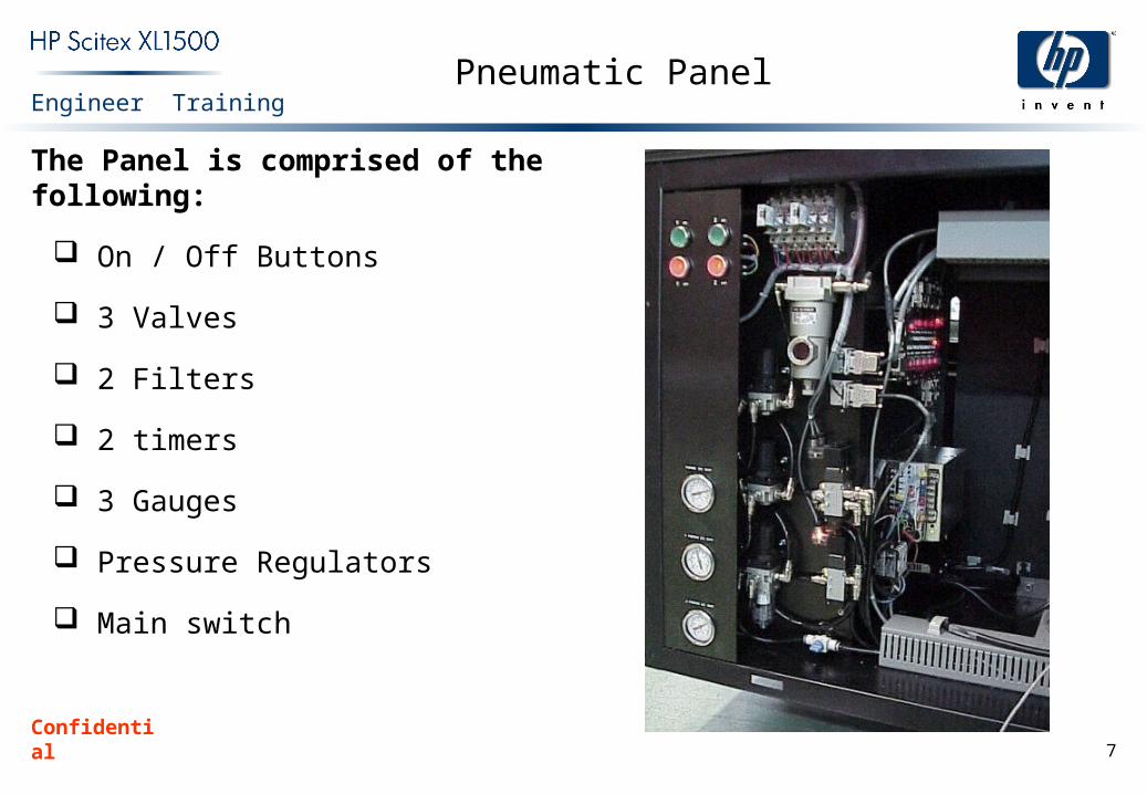
The Panel is comprised of the following:
On / Off Buttons
3 Valves
2 Filters
2 timers
3 Gauges
Pressure Regulators
Main switch

Confidential 8
Engineer TrainingON/OFF Buttons
These 4 buttons control the Z and Y pistons in the following way.
On Y: when the Green Button is pressed, the pressure roller will go UP.The green button will light.
On Z: when The Green Button is pressed, the rubber shaft will go down.The green button will light.
Pressing the Red Buttons, will turn OFF each Shaft; Y will go down, Z willgo UP. The red Button will Light.
Confidential 9
Engineer TrainingTIMERS
There are 2 safety timers which control the delay of each shaft before it starts to move. After pressing any button, an alarm will go off, while the delay is present.
You can adjust this delay in the timers, by rotating the little dial in them, and setting the desired number. The units are in seconds, but that can be changed.

Confidential 10
Engineer Training
The timer has 4 dip switches. The first 2, define the time range and the last 2 the mode. The Correct setting, should be 1 up, and the rest down, so that the range is in seconds.
TIMERS (Cont.)
Confidential 11
Engineer TrainingRegulators and Filters
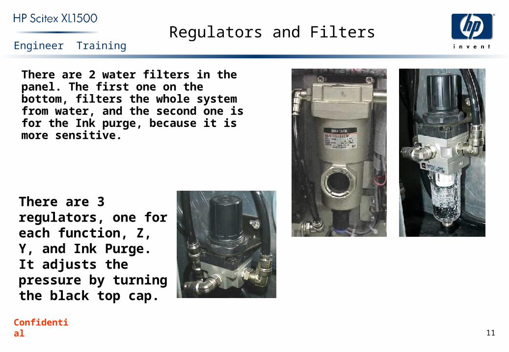
There are 2 water filters in the panel. The first one on the bottom, filters the whole system from water, and the second one is for the Ink purge, because it is more sensitive.
There are 3 regulators, one for each function, Z, Y, and Ink Purge. It adjusts the pressure by turning the black top cap.
Confidential 12
Engineer TrainingGauges and Main Air Valve
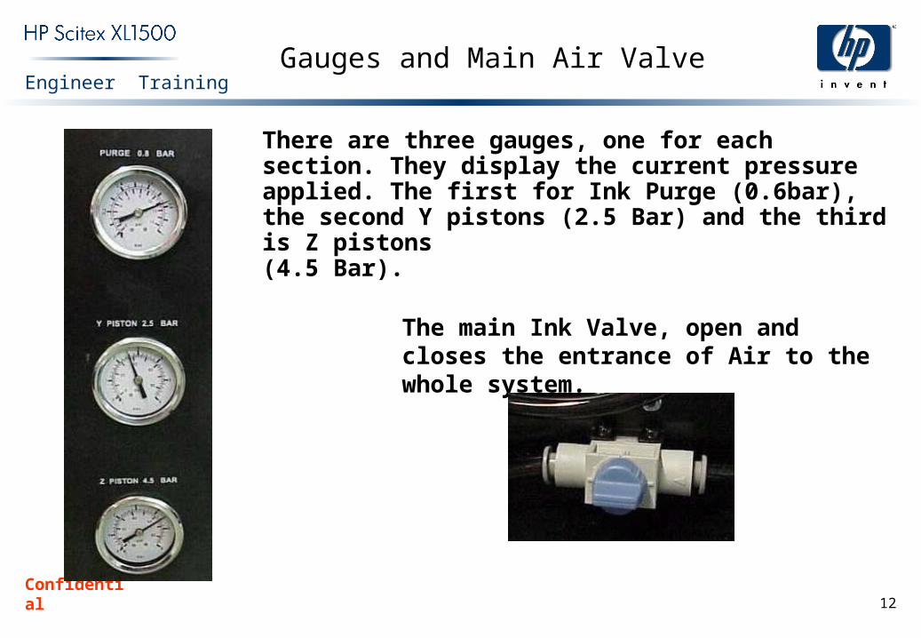
There are three gauges, one for each section. They display the current pressure applied. The first for Ink Purge (0.6bar), the second Y pistons (2.5 Bar) and the third is Z pistons(4.5 Bar).
The main Ink Valve, open and closes the entrance of Air to the whole system.

Confidential 13
Engineer TrainingVALVES
There are 3 electronic valves in the panel. One is for the safety system, which cuts off all air entrances if the emergency button is pressed. And the other two are for the Y and Z piston control.

Confidential 14
Engineer TrainingGeneral Diagram
Ink Purge0.6 Bar
Y Pistons2.5 Bar
Z Pistons4.5 Bar
Ink Purge Air
Regulator
Y AirRegulator
Z AirRegulator
MainValve
Safety Valve
Z Valve
Z Pistons
Y Valve
Y Pistons
Precision Water Trap
To Head Carriage Purge Valves
WaterTrap

Confidential 15
Engineer TrainingSystem Diagram