engineer to engineer note ee-191 - analog.com · uart port on another device. tclkx tfsx dtx drx...
TRANSCRIPT
Engineer To Engineer Note EE-191
a
Technical Notes on using Analog Devices' DSP components and development toolsContact our technical support by phone: (800) ANALOG-D or e-mail: [email protected] visit our on-line resources http://www.analog.com/dsp and http://www.analog.com/dsp/EZAnswers
Implementing a Glueless UART Using The SHARC® DSP SPORTs Contributed by Dan Ledger May 6, 2003
Introduction Using the synchronous serial ports (SPORTS) on the SHARC® DSP, it is possible to implement a full-duplex, asynchronous serial port to communicate with UARTs, EIA-232 (RS-232) devices and MIDI interfaces with minimal software overhead (less than 1 MIP for full-duplex, 115,200 bps operation).
This application note presents both the software and hardware to implement a full UART or RS-232 interface which has been extensively tested in hardware up to 115,200 bits per second. Because the serial ports on SHARC DSP operate well into the tens of megabits/second, the asynchronous interface can operate well beyond 115,200 bps.
Introduction to Asynchronous Serial Communications The primary difference between synchronous and asynchronous serial communication is the presence of a clock signal, and possibly a frame sync signal. A synchronous serial port has both a clock signal and an optional frame sync signal while an asynchronous port does not.
In the absence of a clock signal, asynchronous ports must communicate at a predetermined data rate typically referred to as the bit rate, specifying the bits per second (bps).
In the absence of a frame sync, word framing information is embedded in the data stream. A start-bit and stop-bit typically mark the
beginning and end of a transmission. The word length is predetermined between the receiver and transmitter.
For more information on asynchronous serial communications, visit this website: http://www.freebsd.org/doc/en_US.ISO8859-1/articles/serial-uart/
The Asynchronous SPORT Transmitter
The UART transmitter on the SHARC DSP serial port is quite simple. The transmit side of the serial port must be configured with a clock rate equal to the desired bit rate of the UART. This is done by setting the transmit portion of the clock divider register (DIVx) for that serial port. The formula for calculating the divider value can be found below or in the Serial Port chapter of the appropriate SHARC Hardware Reference Manual.
12
−×
=ratebit
FrequencyClockCoreDSPDivisor
The clock is only used to synchronize the serial port to desired bit rate but the actual clock signal (TCLKx) does not connect to anything. The frame sync signal is also left floating.
The configuration of the transmit side of the SPORT and associated DSP software is presented in detail in the Software Overview portion of this document.
Copyright 2003, Analog Devices, Inc. All rights reserved. Analog Devices assumes no responsibility for customer product design or the use or application of customers’ products or for any infringements of patents or rights of others which may result from Analog Devices assistance. All trademarks and logos are property of their respective holders. Information furnished by Analog Devices Applications and Development Tools Engineers is believed to be accurate and reliable, however no responsibility is assumed by Analog Devices regarding technical accuracy and topicality of the content provided in Analog Devices’ Engineer-to-Engineer Notes.
a The Asynchronous SPORT Receiver
The receive portion is slightly more complicated than the transmit portion as the serial port needs to determine where a new work is beginning without the presence of frame sync signal. To accomplish this, the transmit pin of the UART connects to both the Data Receive pin (DRx) and the Receive Frame Sync (RFSx) on the SHARC DSP SPORT. The RFS pin is polled on the active edge of the internal RCLKx signal by the DSP. When RFS is asserted, the DSP begins receiving a new word and will not check the RFS line until all N (N is programmable in the SPORT control register) bits have been received. The SPORT will thus use the start bit as a frame sync to kick of the reception. As the SPORT has no way of guaranteeing any phase synchronization with the incoming bit stream, it is necessary to over-sample the incoming asynchronous data stream. To accomplish this, the receive clock on the SPORT must be set to three times the desired bit rate. So, for example, if the DSP is communicating with a UART device at 9,600 bits/second, the transmit clock on the SPORT needs to be set at 9,600 bits/second and the receive clock on the SPORT needs to be set at 3 * 9600, or 28,800 bits/second. Again, this is accomplished by calculating the appropriate divisors and programming the DIVx register.
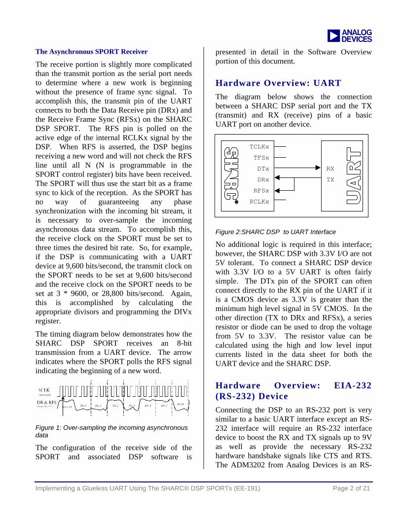
The timing diagram below demonstrates how the SHARC DSP SPORT receives an 8-bit transmission from a UART device. The arrow indicates where the SPORT polls the RFS signal indicating the beginning of a new word.
Figure 1: Over-sampling the incoming asynchronous data
The configuration of the receive side of the SPORT and associated DSP software is
presented in detail in the Software Overview portion of this document.
Hardware Overview: UART The diagram below shows the connection between a SHARC DSP serial port and the TX (transmit) and RX (receive) pins of a basic UART port on another device.
TCLKx
TFSx
DTx
DRx
RFSx
RCLKx
RX
TX
Figure 2:SHARC DSP to UART Interface
No additional logic is required in this interface; however, the SHARC DSP with 3.3V I/O are not 5V tolerant. To connect a SHARC DSP device with 3.3V I/O to a 5V UART is often fairly simple. The DTx pin of the SPORT can often connect directly to the RX pin of the UART if it is a CMOS device as 3.3V is greater than the minimum high level signal in 5V CMOS. In the other direction (TX to DRx and RFSx), a series resistor or diode can be used to drop the voltage from 5V to 3.3V. The resistor value can be calculated using the high and low level input currents listed in the data sheet for both the UART device and the SHARC DSP.
Hardware Overview: EIA-232 (RS-232) Device Connecting the DSP to an RS-232 port is very similar to a basic UART interface except an RS-232 interface will require an RS-232 interface device to boost the RX and TX signals up to 9V as well as provide the necessary RS-232 hardware handshake signals like CTS and RTS. The ADM3202 from Analog Devices is an RS-
Implementing a Glueless UART Using The SHARC® DSP SPORTs (EE-191) Page 2 of 21
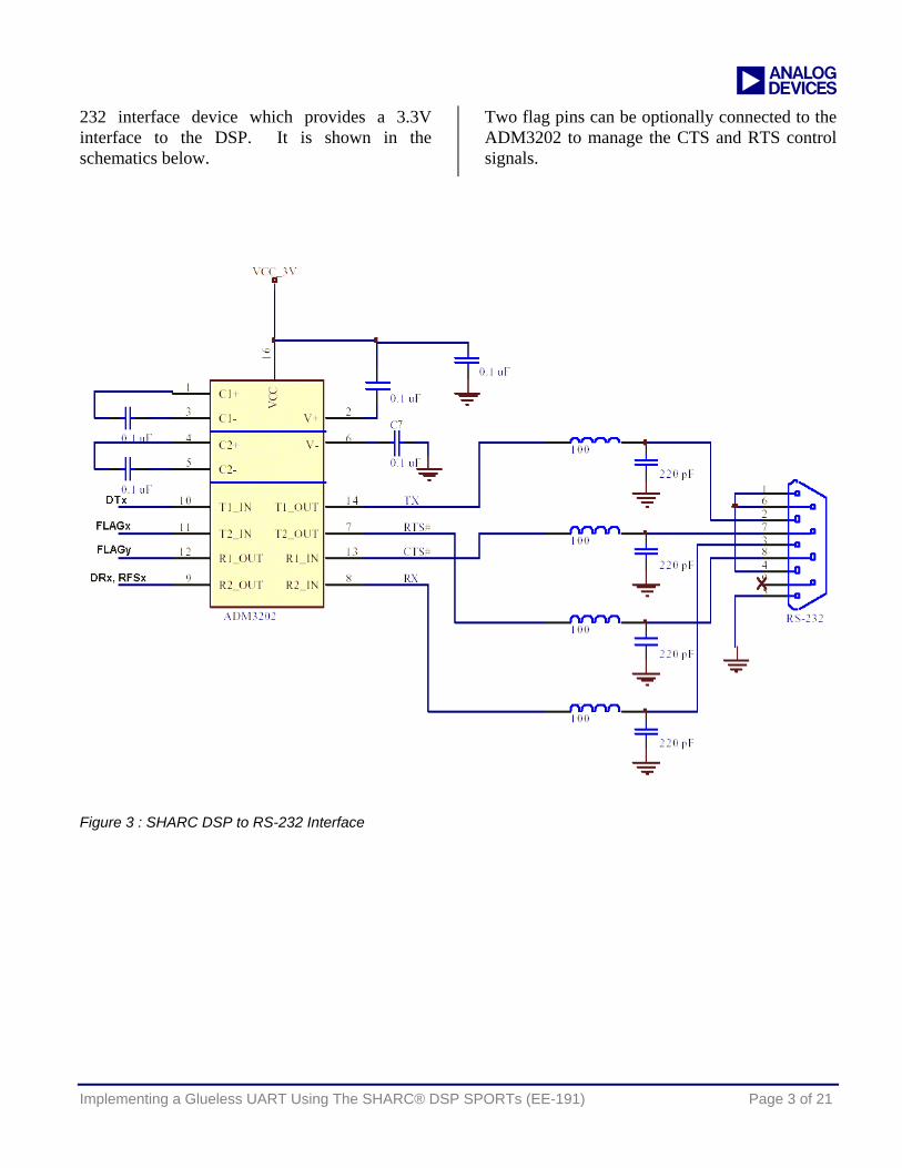
a 232 interface device which provides a 3.3V interface to the DSP. It is shown in the schematics below.
Two flag pins can be optionally connected to the ADM3202 to manage the CTS and RTS control signals.
Figure 3 : SHARC DSP to RS-232 Interface
Implementing a Glueless UART Using The SHARC® DSP SPORTs (EE-191) Page 3 of 21
a
Software Overview The software required to manage the asynchronous data moving in and out of the SPORT is minimal. A full set of C-callable, hand-coded assembly functions is available at the end of this application note and included in the associated .zip file. All code examples in this section are included within the driver code.
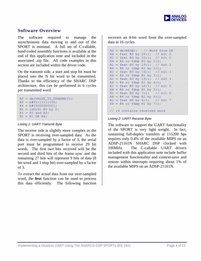
On the transmit side, a start and stop bit must be placed into the N bit word to be transmitted. Thanks to the efficiency of the SHARC DSP architecture, this can be performed in 6 cycles per transmitted word.
R0 = dm(VALUE_TO_TRANSMIT); R2 = b#01111111100; R4 = b#10000000001; R1 = lshift R0 by 2; R1 = R1 and R2; R1 = R1 OR R4;
Listing 1: UART Transmit Byte
The receive side is slightly more complex as the SPORT is receiving over-sampled data. As the data is over-sampled by a factor of 3, the serial port must be programmed to receive 29 bit words. The first two bits received will be the second and third bits of the frame sync and the remaining 27 bits will represent 9 bits of data (8 bit-word and 1 stop bit) over-sampled by a factor of 3.
To extract the actual data from our over-sampled word, the fext function can be used to process this data efficiently. The following function
recovers an 8-bit word from the over-sampled data in 16 cycles.
R0 = dm(RX3B); // Word from DR R4 = fext R0 by 25:1; // bit 0 R1 = fext R0 by 22:1; // bit 1 R4 = R4 or fdep R1 by 1:1; R1 = fext R0 by 19:1; // bit 2 R4 = R4 or fdep R1 by 2:1; R1 = fext R0 by 16:1; // bit 3 R4 = R4 or fdep R1 by 3:1; R1 = fext R0 by 13:1; // bit 4 R4 = R4 or fdep R1 by 4:1; R1 = fext R0 by 10:1; // bit 5 R4 = R4 or fdep R1 by 5:1; R1 = fext R0 by 7:1; // bit 6 R4 = R4 or fdep R1 by 6:1; R1 = fext R0 by 4:1; // bit 7 R4 = R4 or fdep R1 by 7:1; // r4 contains received word
Listing 2: UART Receive Byte
The software to support the UART functionality of the SPORT is very light weight. In fact, sustaining full-duplex transfers at 115200 bps requires only 0.4% of the available MIPS on an ADSP-21161N SHARC DSP clocked with 100MHz. The C-callable UART drivers included with this application note include buffer management functionality and context-save and restore within interrupts requiring about 1% of the available MIPS on an ADSP-21161N.
Implementing a Glueless UART Using The SHARC® DSP SPORTs (EE-191) Page 4 of 21
a
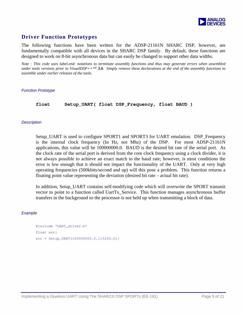
Driver Function Prototypes The following functions have been written for the ADSP-21161N SHARC DSP, however, are fundamentally compatible with all devices in the SHARC DSP family. By default, these functions are designed to work on 8-bit asynchronous data but can easily be changed to support other data widths. Note : This code uses label.end: notations to terminate assembly functions and thus may generate errors when assembled under tools versions prior to VisualDSP++™ 3.0. Simply remove these declarations at the end of the assembly functions to assemble under earlier releases of the tools.
Function Prototype float Setup_UART( float DSP_Frequency, float BAUD )
Description
Setup_UART is used to configure SPORT1 and SPORT3 for UART emulation. DSP_Frequency is the internal clock frequency (In Hz, not Mhz) of the DSP. For most ADSP-21161N applications, this value will be 100000000.0. BAUD is the desired bit rate of the serial port. As the clock rate of the serial port is derived from the core clock frequency using a clock divider, it is not always possible to achieve an exact match to the baud rate; however, is most conditions the error is low enough that it should not impact the functionality of the UART. Only at very high operating frequencies (500kbits/second and up) will this pose a problem. This function returns a floating point value representing the deviation (desired bit rate – actual bit rate). In addition, Setup_UART contains self-modifying code which will overwrite the SPORT transmit vector to point to a function called UartTx_Service. This function manages asynchronous buffer transfers in the background so the processor is not held up when transmitting a block of data.
Example
#include “UART_driver.h”
float err;
err = Setup_UART(100000000.0,115200.0);
Implementing a Glueless UART Using The SHARC® DSP SPORTs (EE-191) Page 5 of 21
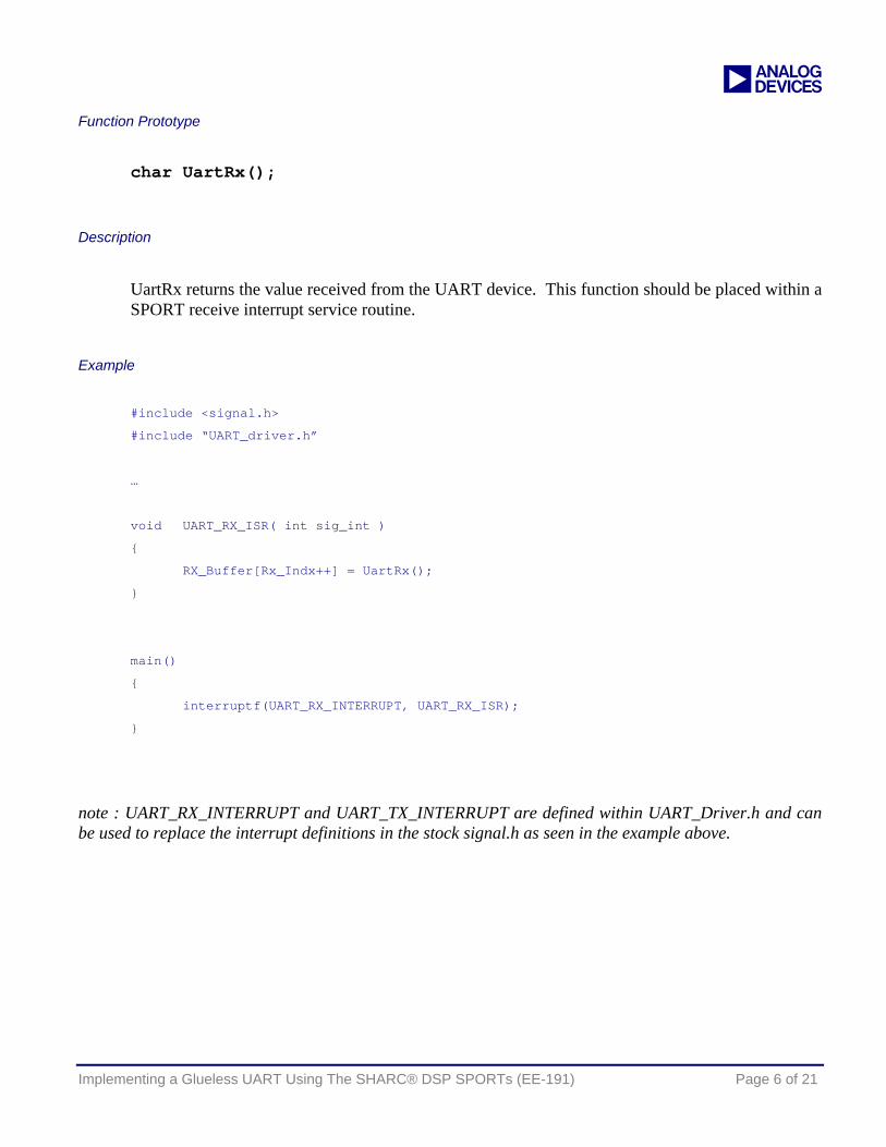
a Function Prototype
char UartRx();
Description
UartRx returns the value received from the UART device. This function should be placed within a SPORT receive interrupt service routine.
Example #include <signal.h>
#include “UART_driver.h”
…
void UART_RX_ISR( int sig_int )
{
RX_Buffer[Rx_Indx++] = UartRx();
}
main()
{
interruptf(UART_RX_INTERRUPT, UART_RX_ISR);
}
note : UART_RX_INTERRUPT and UART_TX_INTERRUPT are defined within UART_Driver.h and can be used to replace the interrupt definitions in the stock signal.h as seen in the example above.
Implementing a Glueless UART Using The SHARC® DSP SPORTs (EE-191) Page 6 of 21
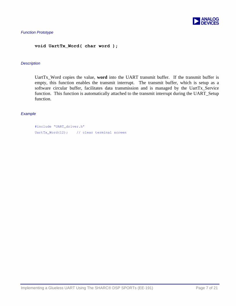
a Function Prototype
void UartTx_Word( char word );
Description
UartTx_Word copies the value, word into the UART transmit buffer. If the transmit buffer is empty, this function enables the transmit interrupt. The transmit buffer, which is setup as a software circular buffer, facilitates data transmission and is managed by the UartTx_Service function. This function is automatically attached to the transmit interrupt during the UART_Setup function.
Example #include “UART_driver.h”
UartTx_Word(12); // clear terminal screen
Implementing a Glueless UART Using The SHARC® DSP SPORTs (EE-191) Page 7 of 21

a Function Prototype
void UartTx_Buffer( char * buf, int size );
Description
UartTx_Buffer copies an entire buffer pointed to by buf with length size into the UART transmit buffer. If the transmit buffer is empty, this function enables the transmit interrupt. The transmit buffer, which is setup as a software circular buffer, facilitates data transmission and is managed by the UartTx_Service function.
Example #include “UART_driver.h”
#include “stdio.h”
char out_string[256];
sprintf(out_string,"ADSP-21161N UART Driver\r\n\r\n");
UartTx_Buffer(out_string, strlen(out_string) );
Implementing a Glueless UART Using The SHARC® DSP SPORTs (EE-191) Page 8 of 21

a Function Prototype
void UartTx_Service( void );
Description
The UartTx_Service routine is automatically setup by the Setup_UART function. This function is responsible for managing the transmit buffer and the transmit interrupt. This function should not be explicitly called in an application.
Implementing a Glueless UART Using The SHARC® DSP SPORTs (EE-191) Page 9 of 21
a
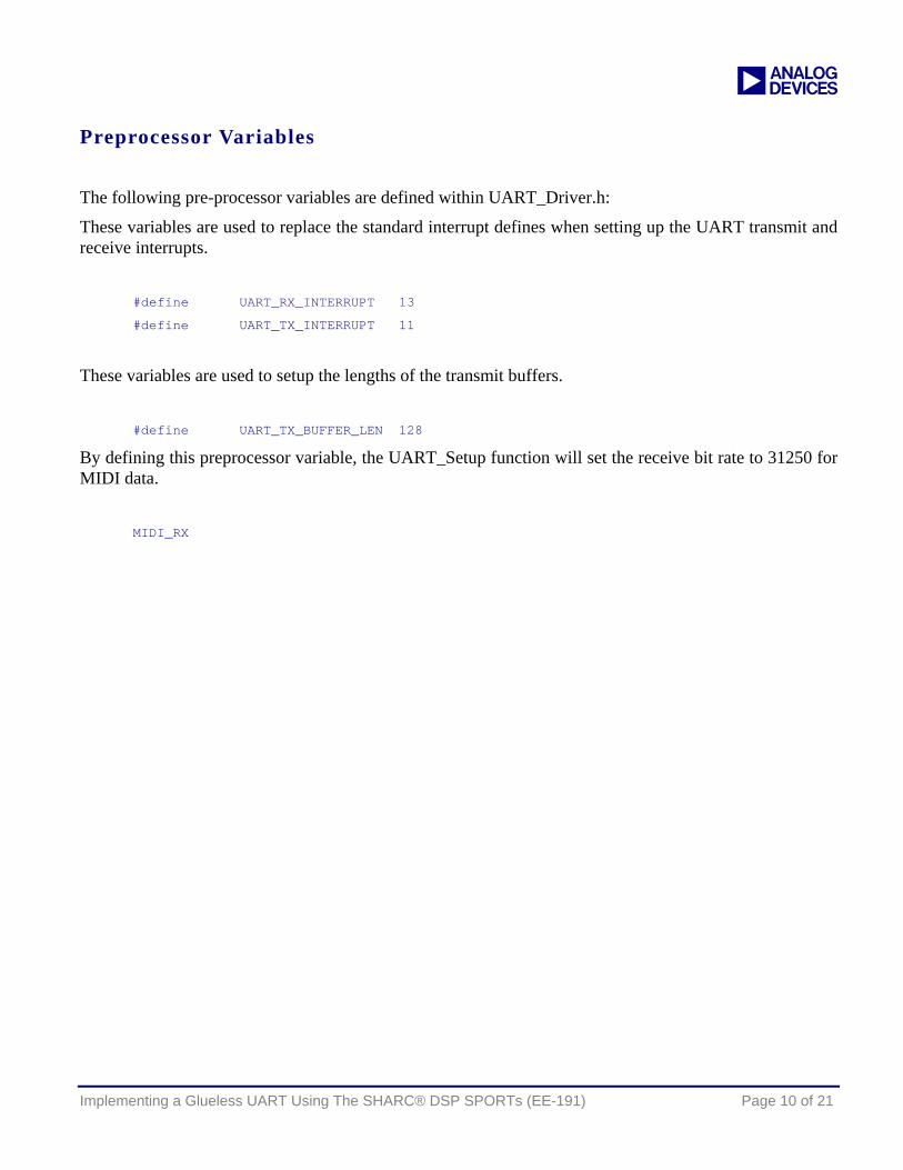
Preprocessor Variables
The following pre-processor variables are defined within UART_Driver.h:
These variables are used to replace the standard interrupt defines when setting up the UART transmit and receive interrupts.
#define UART_RX_INTERRUPT 13
#define UART_TX_INTERRUPT 11
These variables are used to setup the lengths of the transmit buffers.
#define UART_TX_BUFFER_LEN 128
By defining this preprocessor variable, the UART_Setup function will set the receive bit rate to 31250 for MIDI data.
MIDI_RX
Implementing a Glueless UART Using The SHARC® DSP SPORTs (EE-191) Page 10 of 21
a
Code Listing for UART_Driver_.asm
#include <def21161.h>
#include <asm_sprt.h>
#include "UART_Driver.h"
.section /dm seg_dmda;
.var _UART_Error = 0;
.global _UART_Error;
/***************************************************************************************
EZ-UART/MIDI Driver
written by Dan Ledger
last modified 1/2003
Note : This driver is currently configured to transmit on SPORT1 and receive on SPORT3.
Rev 1.4
Revision History
1.0 - original driver
1.1 - added push sts to interrupt routines
1.2 - added automatic setup of interrupt vectors
1.3 - changed length of receive SPORT to 29
1.4 - corrected bug in UARTTX_Service - as this routine is no longer called from
C but rather is automatically called from the ISR, the return should be an
RTI, not leaf_exit;
****************************************************************************************/
Implementing a Glueless UART Using The SHARC® DSP SPORTs (EE-191) Page 11 of 21

a /***************************************************************************************
Setup_UART
Input:
r4 = DSP operating frequency
r8 = desired BAUD rate
Output:
f0 = divisor error. this is the fractional portion resulting from the truncation
to fixed point of the sport clock divisor
C Prototype:
float Setup_UART( float DSP_Frequency, float BAUD );
****************************************************************************************/
.section /pm seg_pmco;
_Setup_UART:
.global _Setup_UART;
r0=0x00000000; // initially clear SPORT control register
dm(SPCTL1)=r0; // tx on sport 1
dm(SPCTL3)=r0; // rx on sport 3
dm(SP13MCTL) = R0;
ustat1=r0;
// Setup SPORT1 - Transmit
bit set ustat1 DDIR | SENDN | LAFS | LFS | IFS | FSR | ICLK | SLEN11 | SPEN_A;
dm(SPCTL1) = ustat1;
// Setup SPORT3 - Receive
ustat1 = 0;
bit set ustat1 LAFS | LFS | FSR | ICLK | SLEN29 | SPEN_B | CKRE;
dm(SPCTL3) = ustat1;
// Calculate divisors based on DSP clock frequency and BAUD rate
r2=1086324736;
F2=F2*F8;
F1=recips F2;
r8=1073741824;
F12=F1*F2;
F4=F1*F4, F2=F8-F12;
F12=F2*F12;
Implementing a Glueless UART Using The SHARC® DSP SPORTs (EE-191) Page 12 of 21

a F4=F2*F4, F2=F8-F12;
F12=F2*F12;
F4=F2*F4, F2=F8-F12;
r8=pass r2;
F2=F2*F4, F12=F8-F12;
F12=F12*F2;
F0=F12+F2;
R4 = FIX F0;
F8 = FLOAT R4;
F0 = F0-F8;
R8 = 3;
R12 = R4 * R8 (uui);
// Setup Transmit
R1 = 11<<16; // 32 bits per frame
R2 = R1 + R12;
dm(DIV1) = R2;
// Setup Receive
// To enable MIDI RX with UART transmit, hardwire RX clock to 31250
#ifdef MIDI_RX
R4 = 533;
#endif
dm(DIV3) = R4;
// setup SPORT1 and SPORT3 ISRs
// UART Transmit
r0 = _UartTx_Service;
r1 = lshift r0 by 16;
px1 = r1;
r1 = b#000001100011111;
r0 = lshift r0 by -16;
r1 = lshift r1 by 17;
r1 = r1 OR r0;
px2 = r1;
pm(0x4002C) = px;
px2 = 0x0b3e0000;
px1 = 0;
pm(0x4002D) = px;
pm(0x4002E) = px;
Implementing a Glueless UART Using The SHARC® DSP SPORTs (EE-191) Page 13 of 21

a pm(0x4002F) = px;
bit set imask SP1I | SP3I;
leaf_exit;
_Setup_UART.end:
Implementing a Glueless UART Using The SHARC® DSP SPORTs (EE-191) Page 14 of 21
a /***************************************************************************************
UartTX_Service
Description:
This function handles the TX interrupt and moving data from the UART_Transmit_Buffer
out to the serial port. This function should be placed in the SPORT 1 ISR.
****************************************************************************************/
.section /dm seg_dmda;
.var UART_Transmit_Buffer[UART_TX_BUFFER_LEN];
.var UART_Transmit_Buffer_Read_Ptr=0;
.var UART_Transmit_Buffer_Write_Ptr=0;
.section /pm seg_pmco;
_UartTx_Service:
.global _UartTx_Service;
push sts;
// * BACKUP VARIABLES
puts = r0;
puts = r1;
// * END BACKUP VARIABLES
r0 = dm(UART_Transmit_Buffer_Read_Ptr);
r1 = dm(UART_Transmit_Buffer_Write_Ptr);
comp(r0,r1);
if eq jump UART_Nothing_To_Transmit;
// BACKUP MORE VARIABLES
r1 = i4; puts = r1;
r1 = m4; puts = r1;
puts = r4;
i4 = UART_Transmit_Buffer;
m4 = dm(UART_Transmit_Buffer_Read_Ptr);
r4 = dm(m4,i4);
// increment pointer
r0 = m4; r0 = r0 + 1;
Implementing a Glueless UART Using The SHARC® DSP SPORTs (EE-191) Page 15 of 21
a
// See if pointer has wrapped
r1 = UART_TX_BUFFER_LEN;
comp(r1,r0);
if EQ r0 = r0 - r1;
dm(UART_Transmit_Buffer_Read_Ptr) = r0;
dm(TX1A) = r4;
// * RESTORE VARIABLES
r4 = gets(1);
r1 = gets(2); m4 = r1;
r1 = gets(3); i4 = r1;
r1 = gets(4);
r0 = gets(5);
alter(5);
pop sts;
rti;
// * END RESTORE VARIABLES
// If there is nothing more to transmit, disable the transmit interrupt
UART_Nothing_To_Transmit:
bit clr IMASK SP1I;
// * RESTORE VARIABLES
r1 = gets(1);
r0 = gets(2);
alter(2);
pop sts;
rti;
// * END RESTORE VARIABLES
_UartTx_Service.end:
Implementing a Glueless UART Using The SHARC® DSP SPORTs (EE-191) Page 16 of 21
a /***************************************************************************************
Uart_TX_Word
Description:
This function writes a value to the SPORT1 transmit register. It first takes
the 8-bit value and creates a 30-bit value for transmitting.
****************************************************************************************/
.section /pm seg_pmco;
_UartTx_Word:
.global _UartTx_Word;
r0 = r4;
r2 = b#01111111100;
r4 = b#10000000001;
r1 = lshift r0 by 2;
r1 = r1 and r2;
r1 = r1 OR r4;
r0 = dm(UART_Transmit_Buffer_Read_Ptr);
r2 = dm(UART_Transmit_Buffer_Write_Ptr);
r0 = r0 - 1;
comp(r0,r2);
if eq jump UART_TX_Full;
i4 = UART_Transmit_Buffer;
m4 = dm(UART_Transmit_Buffer_Write_Ptr);
dm(m4,i4) = r1;
// increment pointer
r0 = m4; r0 = r0 + 1;
// See if pointer has wrapped
r1 = UART_TX_BUFFER_LEN;
comp(r1,r0);
if EQ r0 = r0 - r1;
dm(UART_Transmit_Buffer_Write_Ptr) = r0;
// if the transmit interrupt had been disabled, re-enable it to transmit this new data
bit clr IRPTL SP1I;
bit set IMASK SP1I;
leaf_exit;
_UartTx_Word.end:
Implementing a Glueless UART Using The SHARC® DSP SPORTs (EE-191) Page 17 of 21
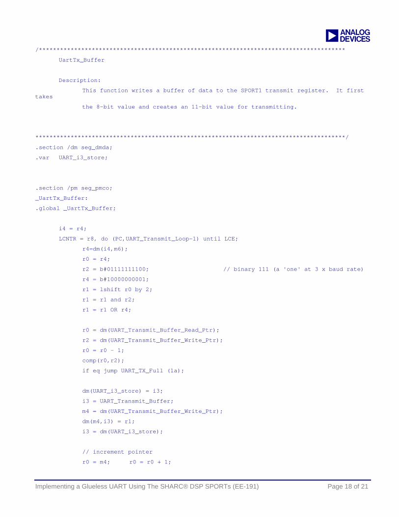
a /***************************************************************************************
UartTx_Buffer
Description:
This function writes a buffer of data to the SPORT1 transmit register. It first takes
the 8-bit value and creates an 11-bit value for transmitting.
****************************************************************************************/
.section /dm seg_dmda;
.var UART_i3_store;
.section /pm seg_pmco;
_UartTx_Buffer:
.global _UartTx_Buffer;
i4 = r4;
LCNTR = r8, do (PC,UART_Transmit_Loop-1) until LCE;
r4=dm(i4,m6);
r0 = r4;
r2 = b#01111111100; // binary 111 (a 'one' at 3 x baud rate)
r4 = b#10000000001;
r1 = lshift r0 by 2;
r1 = r1 and r2;
r1 = r1 OR r4;
r0 = dm(UART_Transmit_Buffer_Read_Ptr);
r2 = dm(UART_Transmit_Buffer_Write_Ptr);
r0 = r0 - 1;
comp(r0,r2);
if eq jump UART_TX_Full (la);
dm(UART_i3_store) = i3;
i3 = UART_Transmit_Buffer;
m4 = dm(UART_Transmit_Buffer_Write_Ptr);
dm(m4,i3) = r1;
i3 = dm(UART_i3_store);
// increment pointer
r0 = m4; r0 = r0 + 1;
Implementing a Glueless UART Using The SHARC® DSP SPORTs (EE-191) Page 18 of 21
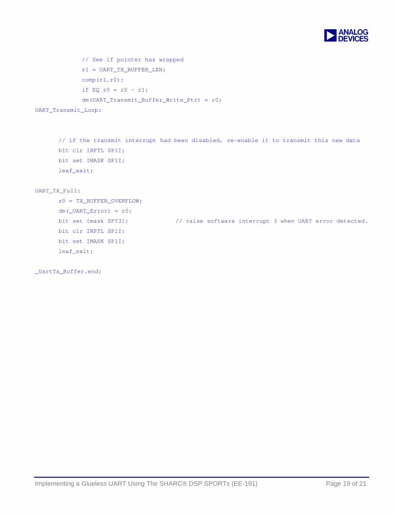
a
// See if pointer has wrapped
r1 = UART_TX_BUFFER_LEN;
comp(r1,r0);
if EQ r0 = r0 - r1;
dm(UART_Transmit_Buffer_Write_Ptr) = r0;
UART_Transmit_Loop:
// if the transmit interrupt had been disabled, re-enable it to transmit this new data
bit clr IRPTL SP1I;
bit set IMASK SP1I;
leaf_exit;
UART_TX_Full:
r0 = TX_BUFFER_OVERFLOW;
dm(_UART_Error) = r0;
bit set imask SFT3I; // raise software interrupt 3 when UART error detected.
bit clr IRPTL SP1I;
bit set IMASK SP1I;
leaf_exit;
_UartTx_Buffer.end:
Implementing a Glueless UART Using The SHARC® DSP SPORTs (EE-191) Page 19 of 21
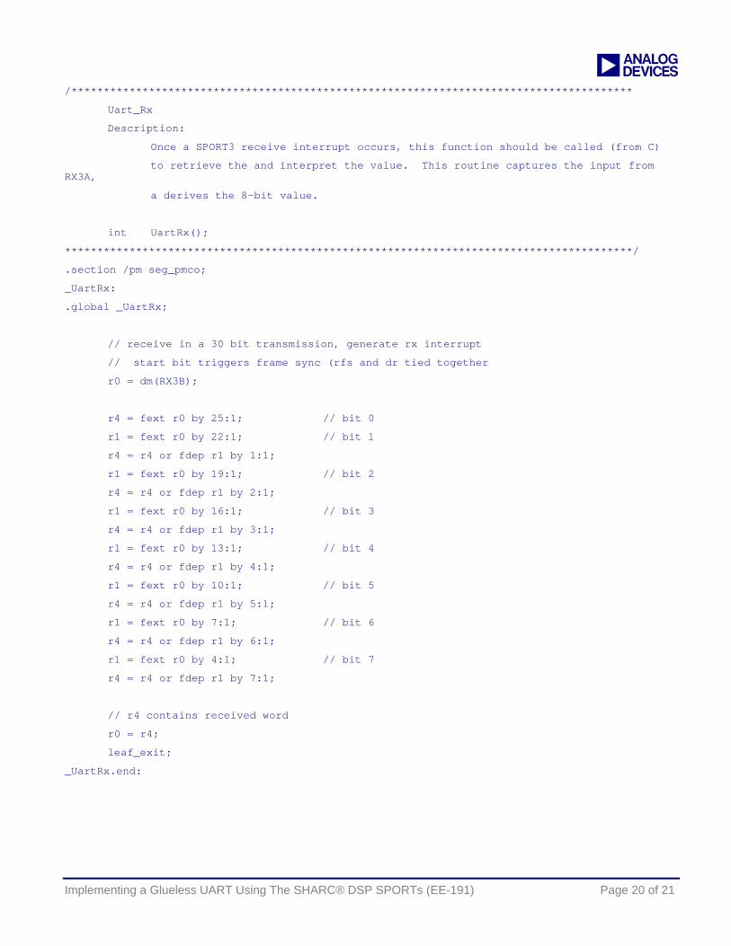
a /***************************************************************************************
Uart_Rx
Description:
Once a SPORT3 receive interrupt occurs, this function should be called (from C)
to retrieve the and interpret the value. This routine captures the input from RX3A,
a derives the 8-bit value.
int UartRx();
****************************************************************************************/
.section /pm seg_pmco;
_UartRx:
.global _UartRx;
// receive in a 30 bit transmission, generate rx interrupt
// start bit triggers frame sync (rfs and dr tied together
r0 = dm(RX3B);
r4 = fext r0 by 25:1; // bit 0
r1 = fext r0 by 22:1; // bit 1
r4 = r4 or fdep r1 by 1:1;
r1 = fext r0 by 19:1; // bit 2
r4 = r4 or fdep r1 by 2:1;
r1 = fext r0 by 16:1; // bit 3
r4 = r4 or fdep r1 by 3:1;
r1 = fext r0 by 13:1; // bit 4
r4 = r4 or fdep r1 by 4:1;
r1 = fext r0 by 10:1; // bit 5
r4 = r4 or fdep r1 by 5:1;
r1 = fext r0 by 7:1; // bit 6
r4 = r4 or fdep r1 by 6:1;
r1 = fext r0 by 4:1; // bit 7
r4 = r4 or fdep r1 by 7:1;
// r4 contains received word
r0 = r4;
leaf_exit;
_UartRx.end:
Implementing a Glueless UART Using The SHARC® DSP SPORTs (EE-191) Page 20 of 21

a
References Thanks to Greg Geerling for coming up with this innovative emulation method and authoring the core transmit and receive functions.
Document History
Version Description
May 6, 2003 by D.Ledger Initial Release
Implementing a Glueless UART Using The SHARC® DSP SPORTs (EE-191) Page 21 of 21