engineer presentation. efficiency - gas clamshell heat exchanger 80% efficient
TRANSCRIPT

Engineer Presentation

Efficiency - GAS

Clamshell Heat Exchanger80% Efficient

Typical two furnace unit
1700 °F
400 °F

Typical two furnace unit
20°F 70°F 120°F
80% Efficient
75% Efficient
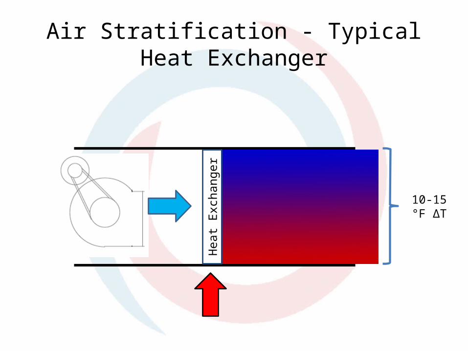
Air Stratification - Typical Heat Exchanger
Hea
t Exc
hang
er10-15 °F
ΔT

Tubular Heat Exchanger 82-83% Efficient
1700 °F
350 °F

Primary Secondary
93% Efficient 91% Efficient
1700 °F
150 °F

Sizing - Series
20°F 70°F 120°F
91% Efficient
86% Efficient

Sizing - Parallel
300 MBH input
600 MBH input
91% Efficient
91% Efficient

Air Stratification – High Efficiency
Hea
t Ex
chan
ger
??? °F ΔTH
eat
Exch
ange
r

Minimum Turn Down Limitation
• Single Stage VS Modulation
• The minimum turn down must be set to ensure condensing in the secondary heat exchanger or both heat exchangers must be made out of stainless steel.
• The Power Venter/Draft Inducer’s airflow directly affects the gas to air ratio at the burner. The ratio must be set to keep Air Free CO below 400 PPM.


• Minimize footprint while maximizing efficiency.• Maximum efficiency at the widest range of ambient
& design conditions.• Maximizing user comfort while minimizing operating
cost.• VAV minimum CFM is now limited by the supply fan
instead of heat exchanger.• No stratification issues. • “Green” unit/minimize emissions
Why Hydronic?

Xcelon w/ Integral Condensing Boiler
1700 °F
100 °F
140 °F
90 °F

Air Stratification - Heating
Hot Water Coil

Constant Discharge Temperature
119
119.5
120
120.5
121
121.5
122
February 23th 2012

Performance
• 93% thermal efficiency per BTS2000. With a discharge air temperature set at 70 degrees, that efficiency increases to 98% efficient.
• Fully modulating gas valves.– 10:1 turndown ratio
• Closed Hydronic Loop requiring no water connections at the roof. Only connections are gas, electricity and ductwork.– 35% Glycol Mix protects the unit to -30°F

-40 -10 0 20 40 60 6582.0%
84.0%
86.0%
88.0%
90.0%
92.0%
94.0%
96.0%
98.0%
100.0%
Xcelon Performance at Discharge Air Setpoint Temperatures*
70100120140
Outdoor Air Temperature, °F
Syst
em E
fficie
ncy,
%
Performance

The maximum allowed CO is 400 PPM CO (Air Free)
• Variable speed power venter
• High fire should be between 8.5-9.5% for CO2 and below the maximum 150 PPM for CO.
• Low fire should be between 8.0-8.5% for CO2 and below the maximum 150 PPM for CO.

Efficiency - ELECTRICAL

Clamshell - Static Pressure
• A typical Clamshell Heat Exchanger can have a static pressure drop of 1.12” per furnace.
• This can result in a total static pressure of over 3” through the furnace sections.

Xcelon – Hot Water Coil• Regardless of the BTU input and CFM
selected, the hot water coil was carefully selected to keep the air pressure drop below 0.5” of static.
• This can result in a reduction in motor horse power by up to two sizes.
• Further adding to the electrical savings, all units come with a VFD as standard.

Cooling Coil Bypass
• In cooling mode the bypass damper is closed forcing the air through the cooling coil.
• When not in cooling mode, the bypass damper opens to reduce the internal static pressure of the unit.
Cooling Coil
Bypass Damper

Efficiency – Heat Recovery

Heat Recovery LayoutBoilerMotor
VFD & Transformer
Pumps
This recovered waste heat increases the efficiency by 1+%

Additional Features

Cincinnati Fan
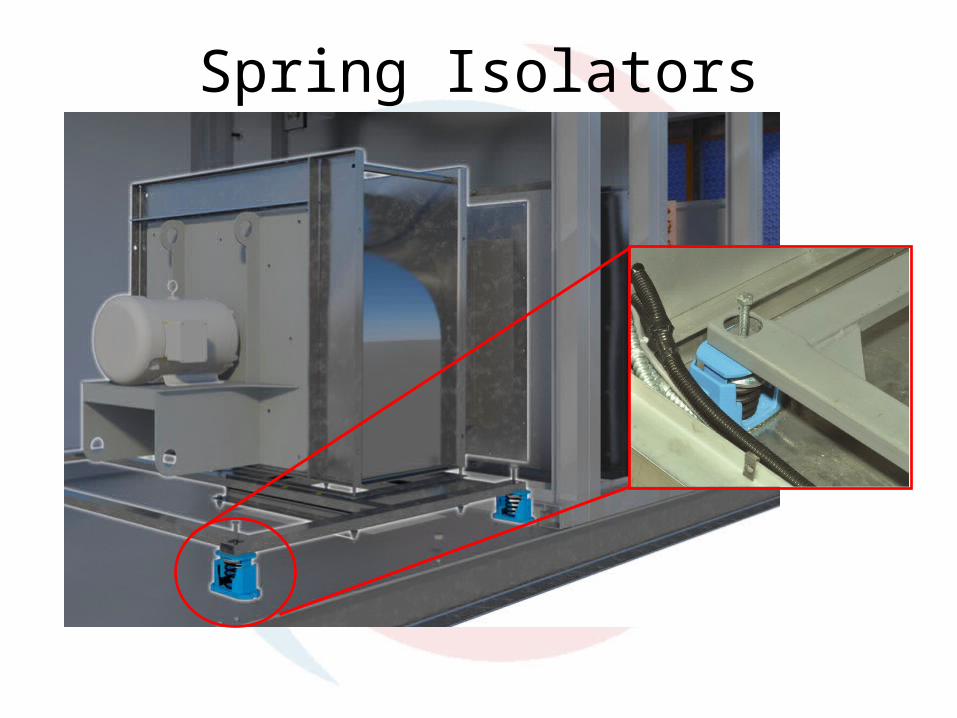
Spring Isolators

Piping
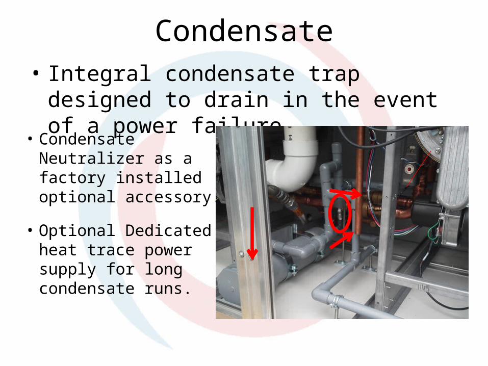
Condensate• Integral condensate trap designed to drain in
the event of a power failure.
• Condensate Neutralizer as a factory installed optional accessory.
• Optional Dedicated heat trace power supply for long condensate runs.

Controls - Overview
1. Call for heat is received.
2. Dampers open and prove.
3. Burners turn on.
4. After glycol mix reaches temperature, VFD slowly ramps up.
5. Glycol mix temperature is varied to maintain constant discharge temperature.
6. (Optional) if the unit is unable to maintain discharge temperature, it reduces the CFM until discharge temp is satisfied.

Controls - Boiler
• The PID loop looks at the Propylene Glycol mix temperature, the discharge air temperature and rate of change.
• HRT Controls are configured to run the first burner to 50% fire then turn on the second burner.
• True run time monitoring

Controls - Safeties
• Boiler – High Limit, Low Water Cutoff, Ignition Control Fault and Software Operator LimitPer code, unit complies with CSD-1.
• Air Side – VFD Temperature Status and Damper Prove

Service
• Designed with ease of service in mind.– Isolation valves for ease of boiler service• Boiler is on a track for ease of repair.
– Service lights standard on all units.– Optional Convenience Outlet available. – Optional Clogged Filter Switch.– External Control Terminal Strip on exterior of unit
for ease of Thermostat wiring.

Roof Cap• The roof cap of the outdoor unit is sloped to
prevent standing water on top of the unit.
• It should be noted that underneath the roof cap is that actual roof of the unit which is a same panel construction as the walls (with the same R-value)

Performance
• Performance– Max Discharge 140 ⁰F, Max temperature rise 100 ⁰F.– 4,501 - 15,000 CFM
• Able to handle 3” of external static pressure
– 800 – 1,600 MBH
• Initial offering– 4,501 to 10,000 CFM– 800 & 1,200 MBH

Questions