engine starting battery charger -...
TRANSCRIPT

La Marche Manufacturing Company | www.lamarchemfg.com
ESCR IIESCR IIESCR IIESCR II Engine Starting Battery Charger
Installation and Operation Manual
106 Bradrock Dr. Des Plaines 60018-19671 Tel: 847 299 1188 Fax: 847 299 3061
Instruction Drawing Number: P25-LESCRII-1 Revision A02 Rev. Date: 07/14 ECN:20488
i
Importtant Safety Instructions
Before using this equipment read all manuals and other documents related to this unit and other equipment connected to this unit. Always have a copy of a units manual on file nearby, in a safe place; if a replacement copy of a manual is needed it can be found at the www.lamarchemfg.com.
Electrical Safety
WARNING: Hazardous Voltages are present at the input of power systems. The output from rectifiers and from batteries may be low in voltage, but can have a very high current capacity that may cause severe or even fatal injury.
When working with any live battery or power system, follow these precautions: • Never work alone on any live power systems, someone should always be close enough to come to your aid. • Remove personal metal items such as rings, bracelets, necklaces, and watches. • Wear complete eye protection (with side shields) and clothing protection. • Always wear gloves and use insulated hand tools.
WARNING: Lethal Voltages are present within the power system. Parts inside the unit may still be energized even when the unit has been disconnected from the AC input power. Check with a meter before proceeding. Do not touch any uninsulated parts.
• A licensed electrician should be used in the installation of any unit. • Always disconnect the unit from the supply, batteries and loads before performing maintenance or cleaning. • If the unit is hot-swappable, simply remove it from the shelf for any maintenance or cleaning. • Always assume that an electrical connection is live and check the connection relative to ground. • Be sure that neither liquids nor any wet material come in contact with any internal components. • Do not operate this unit outside the input and output ratings listed on the unit nameplate. • Do not use this unit for any purpose not described in the operation manual.
Mechanical Safety
• This unit or parts of the unit may get very hot during normal operation, use care when working nearby. • Do not expose equipment to rain or snow. Always install in a clean, dry location. • Do not operate equipment if it has received a sharp blow, been dropped, or otherwise damaged in any way. • Do not disassemble this unit. Incorrect re-assembly may result in a risk of electric shock or fire.
Battery Safety
WARNING: Follow all of the battery manufacturer’s safety recommendations when working with or around battery systems. DO NOT smoke or introduce a spark or open flame in the vicinity of a battery. Some batteries generate explosive gases during normal battery operation.
• To reduce risk of arc, connect and disconnect the battery only when the unit is off. • If it is necessary to remove battery connections, always remove the grounded terminal from the battery first. • Remove personal metal items such as rings, bracelets, necklaces, and watches. • Always wear rubber gloves, safety glasses, and a rubber lined vest/apron when working near a battery. • Have plenty of fresh water and soap nearby in case the battery electrolyte contacts skin, clothing, or eyes. • If the battery electrolyte contacts skin or clothing, wash immediately with soap and water. • If the electrolyte enters the eye, immediately flood the eye with running cold water for at least ten (10)
minutes and seek medical attention immediately. • Do not drop metal on a battery. A spark or short-circuit could occur and could cause an explosion.
ii
Unit Location
• Allow at least 3 inches of free air on all vented surfaces (and external heatsinks) for proper cooling. • Allow sufficient clearance to open the front panel for servicing. • Do not operate this unit in a closed-in area or restrict ventilation in any way. • Do not set any battery on top of this unit. • Never allow battery electrolyte to drip on this unit when reading the specific gravity or filling the battery. • Never place this unit directly above a standard flooded battery. Gases from the battery will corrode and
damage equipment. • A sealed maintenance free or valve regulated lead acid (VRLA) battery may be placed below this equipment.
Check for Damages
Prior to unpacking the product, note any damage to the shipping container. Unpack the product and inspect the exterior of product for damage. If any damage is observed, contact the carrier immediately. Continue the inspection for any internal damage. In the unlikely event of internal damage, please inform the carrier and contact La Marche for advice on the risk due to any damage before installing the product. Verify that you have all the necessary parts per your order for proper assembly.
CAUTION: Failure to properly file a claim for shipping damages, or provide a copy of the claim to La Marche, may void warranty service for any physical damages reported for repair.
Returns for Service
Save the original shipping container. If the product needs to be returned for service, it should be packaged in its original shipping container. If the original container is damaged/unavailable, make sure the product is packed with at least three inches of shock-absorbing material to prevent shipping damage. La Marche is not responsible for damage caused by improper packaging of returned products.
Inspection Checklist
Enclosure exterior and interior is not marred or dented. There is no visible damage components. All internal components are secure. Printed circuit boards are firmly seated. All hardware and connections are tight. All wire terminations are secure. All items on packing list have been included.
Handling
Equipment can be very heavy and/or top heavy. Use adequate manpower or equipment for handling. Until the equipment is securely mounted, care must be used to prevent the equipment from being accidentally tipped over.
iii
Table of Contents
Important Safety Instructions ................................................................................................................... i
Electrical Safety ................................................................................................................................... i
Mechanical Safety ................................................................................................................................ i
Battery Safety...................................................................................................................................... i
Unit Location .......................................................................................................................................ii
Check for Damages ..............................................................................................................................ii
Returns for Service ...............................................................................................................................ii
Inspection Checklist...........................................................................................................................ii
Handling .............................................................................................................................................ii
Table of Contents ................................................................................................................................... iii
Table of Figures ..................................................................................................................................... iv
Model Scope/General Description ............................................................................................................. v
Understanding the Model Number ............................................................................................................ v
Optional Accessories Included in the Unit .................................................................................................. v
1 Installation ...................................................................................................................................... 1
1.1 Mounting the ESCR II ............................................................................................................... 1
1.1.1 Wall Mounting ...................................................................................................................... 1
1.1.2 Floor Mounting ..................................................................................................................... 1
1.2 Electrical Connections ............................................................................................................... 2
1.2.1 Changing Transformer Taps ................................................................................................... 2
1.2.2 AC Input Connections............................................................................................................ 2
1.2.3 Output Connections............................................................................................................... 3
1.2.4 Standard Alarms ................................................................................................................... 4
2 Operation........................................................................................................................................ 7
2.1 Starting the ESCR II ................................................................................................................. 7
2.1.1 Checking the Installation ....................................................................................................... 7
2.1.2 Starting/Stopping the ESCR II............................................................................................. 7
2.1.3 Start-Up Sequence ................................................................................................................ 7
2.2.1 Controls ............................................................................................................................... 8
2.2.2 LED Indicators/Alarms ....................................................................................................... 9
2.3 Configure Mode........................................................................................................................ 9
2.3.2 Basic Settings....................................................................................................................... 9
3 Service...........................................................................................................................................13
3.1 Performing Routine Maintenance...............................................................................................13
3.2 Troubleshooting Procedure .......................................................................................................14
3.3 Troubleshooting Chart..............................................................................................................15
Appendix A: ESCR II Specifications ..........................................................................................................16
Appendix B: Manufacturer’s Warranty………………………………………………………………………………………………………17
Appendix C: Document Control and Revision History..................................................................................17

iv
Table of Figures
Figure 1 - ESCR II Mounting Dimensions ................................................................................................... 1 Figure 2 - AC Input Taps ......................................................................................................................... 1 Figure 3 - Standard Customer Connection Card.......................................................................................... 1 Figure 4 - Example Connections (Customer Provided Equipment) ................................................................. 1 Figure 5 - Temperature Probe Connection ................................................................................................. 6 Figure 6 - Front Panel Display (Unit in Float Mode)..................................................................................... 8
Table 1 - ESCR II Weights and Dimensions................................................................................................ 1 Table 2 - AC Input Taps .......................................................................................................................... 1 Table 3 - Wire Sizing Table ...................................................................................................................... 3 Table 4 - Wire Size/Area Table................................................................................................................. 3 Table 5 - Configure Mode Flow Chart .......................................................................................................12

v
Model Scope/General Description
The La Marche model ESCR II engine starting battery charger product line utilizes microprocessor controlled SCR Charging Technology. The PWM control provides the highest reliability that is required for maintaining and recharging engine start batteries for generator sets. The ESCR II features adjustable Float and Equalize voltages, soft start, equalize timer and is configurable for Flooded Lead Acid, NiCad or VRLA batteries. The ESCR II offers both AC and DC breakers as standard equipment. The ESCR II can run at both 50 and 60Hz.
Understanding the Model Number
The ESCR model number is coded to describe the charger and the options that are included. Find the model number on the nomenclature nameplate of the charger. Then follow the chart to determine the configuration of your battery charger.
Optional Accessories Included in the Unit
This unit may have been outfitted with a number of optional accessories or option packages. To find out what options this unit has (if any) refer to the very first page of the manual package.

1
1 Installation
1.1 Mounting the ESCR II
For customer convenience the ESCR II can either be wall or floor mounted. Be sure that the Wall or Floor planned for installation can support the weight of the ESCR II.
Amps Volts Amps Volts
16.837” x 10.625” x 19.7” 100 lbs
427.7 x 269.9 x 500.4mm 45.36 kg
16.837” x 10.625” x 19.7” 107 lbs
427.7 x 269.9 x 500.4mm 48.55 kg
16.837” x 10.625” x 19.7” 130 lbs
427.7 x 269.9 x 500.4mm 58.97 kg
16.837” x 10.625” x 19.7” 112 lbs
427.7 x 269.9 x 500.4mm 50.80 kg*The ZF1 unit can run at 60Hz over the full input range. At 50Hz it can only be run at 400VAC (± 10%)
ESCR-30-24V-AV1 18/8-9120/208-240
50/60Hz30 24
ESCR-50-24V-AV1 24/11.5-12120/208-240
50/60Hz50 24
ESCR-40-24V-AV1 22/10-11120/208-240
50/60Hz40 24
Model NumberAC Input DC Output
Dimensions Weight
24ESCR-40-24V-ZF1 6-7400-480
50/60Hz*40
Table 1 - ESCR II Weights and Dimensions
1.1.1 Wall Mounting
To wall-mount the ESCR II, install three 0.25 in (6.4 mm) bolts on the wall rated to support the charger weight plus a safety factor of at least two times. Place the ESCR II on the bolts, add appropriate mounting hardware and tighten. Add two 0.25 in bolts to the bottom brackets for additional support. Refer to the figure below (left) for mounting dimensions and specifications.
Figure 1 - ESCR II Mounting Dimensions
1.1.2 Floor Mounting
To floor-mount the ESCR II, install four 0.25in (6.4mm) bolts into the floor. Place the ESCR II on the bolts, add appropriate mounting hardware, and tighten securely. The image above (right) shows the footprint of the ESCR II case.

2
Figure 2 - AC Input Taps
1.2 Electrical Connections
1.2.1 Changing Transformer Taps
The ESCR II accepts standard input voltages of 120 VAC or 208 – 240 VAC by changing the connections to the input terminals. No other changes are required. The ZF1 unit (400-480VAC) has no taps.*
CAUTION: Before wiring AC power to the ESCR II, check the wiring of the power transformer PT, to be sure it is connected for the correct AC input voltage.
Before changing the PT taps, be sure that AC supply and DC loads to the ESCR II are turned off and locked out. Verify that no voltage is present by using a voltmeter at all input and output terminals. Turning off the AC and DC circuit breakers on the ESCR II does NOT eliminate live voltages inside the enclosure. Also de-energize any external wiring to the alarm relay contacts.
Verify that all voltages within the enclosure are de-energized and locked out. Change the connections to the input terminals as shown in the table and figure below.
* An ESCR II battery charger rated for 400 – 480 VAC does not have transformer taps. The unit can be run at 400 – 480VAC (±10%) at 60Hz. At 50Hz the unit can only be run at 400VAC (± 10%).
1.2.2 AC Input Connections
Before beginning any work inside the charger enclosure ensure that all incoming AC supply and DC load wires are de-energized. Verify that no voltage is present inside the case by using a voltmeter at all input and output terminals.
For 120 VAC Input Voltage:
1. Connect wire marked A to terminal 5 2. Connect wire marked B to terminal 6 3. Connect wire marked C to terminal 3 4. AC input 1 connects to terminal 1(L1) 5. AC input 2 connects to terminal 4(N)
For 208 – 240 VAC Input Voltage:
1. Connect wire marked A to terminal 6 2. Connect wire marked B to terminal 5 3. Connect wire marked C to terminal 2 4. AC input 1 connects to terminal 1(L1) 5. AC input 2 connects to terminal 3(L2)
Table 2 - AC Input Taps

3
Before making any connections to the ESCR II ensure that the AC Power is off at the main breaker box and that both of the unit’s breakers are off. Check that the source voltage and frequency matches the voltage and frequency listed on the charger nameplate. Select wire size, using Table 3 to the right.
Connect the AC input wires to the appropriate taps as described above. If the ESCR II has a 480V input there are not taps, simply connect the AC input wires to terminals 1 and 2.
NOTE: These are recommended sizes. All National and Local Wiring Codes must be followed
1.2.3 Output Connections
Before connecting the Battery and/or DC loads, it is recommended to apply AC power and set the configuration for the correct output. See section 2.3 for the configuration instructions. Once the configuration is set remove AC power from the main breaker to the charger.
Select proper size for the DC wiring from the wire size table above (Table 3). If the distance between the unit’s DC output and the DC load exceeds 10 feet, use the Power Cable Guide below to minimize the voltage drop across the wire distance.
Power Cabling Guide
Use the following formulas and table to determine proper wire size for minimal voltage drop. Table of Conventions
CMA = Cross section of wire in circular MIL area A = Ultimate drain in amperes LF = Conductor loop feet MaxAmp = Maximum allowable amperes for given voltage drop AVD = Allowable voltage drop K = 11.1 for commercial (TW) copper wire (KS5482-01) = 7.4 for aluminum (KS20189) Calculating Wire Size Requirements Calculating Current Carrying Capacity of Wire
AVD
KLFACMA
××= KLF
AVDCMAMaxAmp
××=
CAUTION: When connecting the DC cables to the battery, be certain the positive terminal of the charger is connected to the positive battery terminal and the negative terminal is connected to the negative battery terminal.
BREAKER WIRE SIZE EQUIPMENT
SIZE REQUIREMENT GROUNDING
(AMPS) FOR CUSTOMER CONDUCTOR
CONNECTION MINIMUM
5 #14 #14
10 #14 #14
15 #12 #12
20 #12 #12
25 #10 #12
30 #10 #10
35 # 8 #10
40 # 8 #10
45 # 8 #10
50 # 8 #10
60 # 6 #10
Table 3 - Wire Sizing Table
SIZE
(AWG)
AREA
CIR.MILS
SIZE
(AWG)
AREA
CIR.MILS
18 1620 6 26240 16 2580 4 41740 14 4110 3 52620 12 6530 2 66360 10 10380 1 83690 8 16510 0 105600
Table 4 - Wire Size/Area Table
4
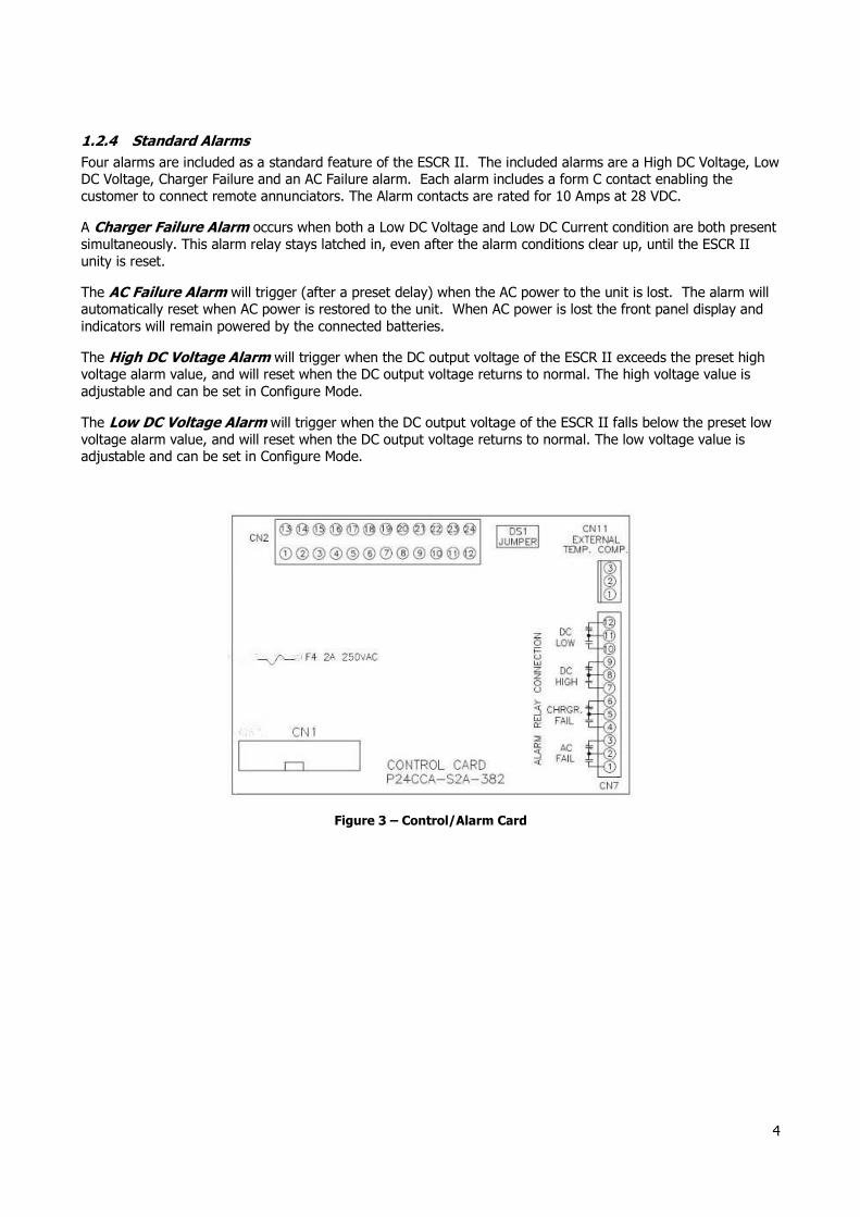
1.2.4 Standard Alarms
Four alarms are included as a standard feature of the ESCR II. The included alarms are a High DC Voltage, Low DC Voltage, Charger Failure and an AC Failure alarm. Each alarm includes a form C contact enabling the customer to connect remote annunciators. The Alarm contacts are rated for 10 Amps at 28 VDC.
A Charger Failure Alarm occurs when both a Low DC Voltage and Low DC Current condition are both present simultaneously. This alarm relay stays latched in, even after the alarm conditions clear up, until the ESCR II unity is reset.
The AC Failure Alarm will trigger (after a preset delay) when the AC power to the unit is lost. The alarm will automatically reset when AC power is restored to the unit. When AC power is lost the front panel display and indicators will remain powered by the connected batteries.
The High DC Voltage Alarm will trigger when the DC output voltage of the ESCR II exceeds the preset high voltage alarm value, and will reset when the DC output voltage returns to normal. The high voltage value is adjustable and can be set in Configure Mode.
The Low DC Voltage Alarm will trigger when the DC output voltage of the ESCR II falls below the preset low voltage alarm value, and will reset when the DC output voltage returns to normal. The low voltage value is adjustable and can be set in Configure Mode.
Figure 3 – Control/Alarm Card

5
Alarm Connections
Before making any connections to the ESCR II ensure that the AC Power is off at the main breaker box and that both of the unit’s breakers are off. Verify that no voltage is present by using a voltmeter at all input and output terminals.
If it is desired that the annunciator be active until the alarm triggers connect the annunciator leads to the NO and C contacts of the desired alarm (located on the Control Card S2A-382). If it is desired that the annunciator be activated when an alarm triggers connect the annunciator leads to the NC and C contacts of the desired alarm.
EXAMPLE: A customer wants a Green Lamp to be illuminated while the AC Power is on, and a Speaker to sound when the AC is lost. Using customer provided equipment they could connect a external power supply, a speaker and a green lamp. The speaker would be connected to Pin 1 (NO contact) and the low side of the power supply. The Lamp would be connected to Pin 3 (NC contact) and the low side of the power supply. The high side of the power supply would be connected to Pin 2 (C contact). See Figure 4.
Figure 4 - Example Connections
(Customer Provided Equipment)

6
1.2.5 External Temperature Compensation (Option 11W/11Y) The natural voltage of a battery changes as a function of temperature change. As the battery temperature rises, the effective voltage of the battery decreases. Without Temperature Compensation, the battery charger will always produce a set constant output voltage. As the battery temperature increases, this constant voltage will then induce a higher output current from the charger. This higher current can result in overcharging the battery, which in turn can result in damage to the batteries.
Temperature Compensation combats this overcharging by adjusting the charger’s output voltage based on the temperature read by the temperature probe. In order to increase the accuracy of the temperature compensation the external probe can be used to measure the temperature of the battery.
Option 11W includes the compensation circuit and a 24 foot long temperature probe. Option 11Y includes the compensation circuit and a 100 foot long temperature probe. With either option approximately two feet of the probe is taken inside the charger enclosure.
External Probe Connection Procedure
Before making any connections to the ESCR II ensure that the AC Power is off at the main breaker box and that both of the unit’s breakers are off. Verify that no voltage is present by using a voltmeter at all input and output terminals.
To connect the external probe the DS1 jumper must be removed. Removing this jumper will disable the charger's internal temperature compensation.
On the charger side, simply plug the probe's 3 pin connector in the C11 connection on the Control/Alarm Board. Install the remaining lug of the probe to the battery. As battery setups vary between customers and battery manufacturers, it is recommended that the battery manufacturer be consulted for placement of the probe. The lug of the probe is completely isolated from the compensation circuitry, so the battery voltage will not affect the compensation.
With the probe connected, enter the configuration and make sure that Temperature Compensation has been enabled (For more details see section 2.3).
Figure 5 - Temperature Probe Connection
7
2 Operation
2.1 Starting the ESCR II
All equipment is shipped from the factory fully checked and adjusted based on the factory settings listed below. Before connecting the battery check with the battery manufacturer for the correct voltage settings and adjust the configuration accordingly (refer to section 2.3 for configuration). Failure to match the charger settings with the connected battery may damage or shorten the life of the battery.
Factory Settings The factory settings of the ESCR II are based on the customer order, unless otherwise specified all units are set at the factory with the following settings.
Battery Type: 12L (12 Cell Lead Acid) Float Voltage: 2.25 Volts/Cell (V/C) for Lead Acid (LA) 1.40 V/C for Nickel Cadmium (NC) Equalize Voltage: 2.33 V/C for LA (1.55 V/C for NC) Current Limit: 105% or nominal output current Equalize Hours: Eight Hours Equalize Mode: Manual Temp. Compensation: Disabled High DC Voltage: 2.45 V/C for LA (1.6 V/C for NC) Low DC Voltage: 1.98 V/C for LA (1.2 V/C for NC) Low DC Current: 0.5 Amps Alarm Delay: 5 Seconds
2.1.1 Checking the Installation
Before starting up the ESCR II check and verify that all connections are correct. Check that all terminations and contacts are tightened securely. Check that the transformer is set for the correct voltage and that the input frequency matches the nameplate of the charger. Check that the battery voltage matches the DC output voltage on the nameplate of the charger.
2.1.2 Starting/Stopping the ESCR II
Once proper connections are established energize the charger by turning on the unit’s AC breaker (the DC breaker should be off). This will charge the capacitors inside the unit and eliminate heavy arcing when the batteries are connected. After about 30 seconds, turn on the DC breaker. When shutting down the ESCR II switch off the DC breaker first and then switch off the AC breaker.
2.1.3 Start-Up Sequence
Upon powering up the ESCR II a test sequence is activated. This test flashes all of the units LEDs and activates all alarms. The LCD will display the model and software number.

8
2.2 The Front Panel Display
After the ESCR II has completed start up the “AC ON” indicator on the front panel and either the “Float” or “Equalize” indicator on the front panel will be lit. The LCD will display the system DC output voltage and DC output current on line one. Line two of the LCD displays the status of ESCR II.
Figure 6 - Front Panel Display (Unit in Float Mode)
2.2.1 Controls
Up/Down Arrows – The Up and Down arrows offer no function outside of Configure mode. When in configure mode the up and down arrows allow the customer to navigate menus and increase or decrease values.
Float/Equalize Button – The Float/Equalize Button allows the user to manually switch between float mode and equalize mode. When the ESCR II is in equalize mode, line two of the display will switch between “EQUALIZE MODE” and the time remaining.
Lamp Test Button – The Lamp Test button allows the user to check the function of all of the Front Panel LEDs without affecting the operation of the rectifier. While the lamp test is running all of the LEDs flash and a sequence of numbers is written to the display.
Reset/Back Button – Under normal system operation the Reset/Back Button operates as the reset button. Pressing reset allows the user to restart the rectifier. Upon restarting, the ESCR II will once again go through the start-up sequence describe in section 2.1.3. In the Configure mode the Reset/Back button operates as the back button. Pressing the back button allows the user to navigate to a previous screen or out of the configuration.
Configure/OK Button – The Configure/OK button brings the ESCR II into configuration mode, allowing the user to set charger parameters in Basic Settings as well as Float Voltage, Equalize Voltage, Equalize Timer Current Limit, Temperature Compensation and Alarm settings. Once in configuration mode this button becomes the OK button which is used to make selections with in the menus.

9
2.2.2 LED Indicators/Alarms
LCD Display – The LCD Display show the output DC voltage and output DC amperage of the ESCR at all times. The second line of the Display shows the mode of the charger as well as displaying the different alarm conditions should they occur.
Float LED (Green) – The Float LED with illuminate when the ESCR II is in float mode.
Equalize LED (Amber) – The Equalize LED will illuminate when the ESCR II is in equalize mode.
AC On (Green) – The AC On LED will illuminate whenever AC voltage is present at the ESCR II input terminals.
Charger Fail LED (Red) – The Charger Fail LED will illuminate when both a low voltage and low current condition are present simultaneously. A set of Form C contacts is also provided to enable the customer to connect a remote annunciator.
Battery Fault LED (Red) - The Battery Failure LED illuminates to indicate a issue with the battery. Conditions that would cause this LED to illuminate are an open or high resistance battery, or a missing battery.
Current Limit (Red) – The Current Limit LED will illuminate when the rectifier is operating in a current limit condition
High DC (Red) – The High DC LED will illuminate when the DC output voltage of the ESCR II exceeds the preset high voltage alarm value. The high voltage value is adjustable and can be set in Configure Mode. A set of Form C contacts is also provided.
Low DC (Red) – The Low DC LED will illuminate when the DC output voltage of the ESCR II falls below the preset low voltage alarm value. The low voltage value is adjustable and can be set in Configure Mode. A set of Form C contacts is also provided.
AC Fail (contacts only) – The AC Fail alarm does not have an LED indicator, however, an AC Fail message appears on the LCD display. A set of Form C contacts is provided for an AC Power Failure Alarm annunciation. These contacts change state when AC Fail threshold is reached.
2.3 Configure Mode
Pressing the Configure/OK button enters Configure mode. In configure mode the rectifier is turned off, and there will be no output. The customer must be careful that this button is not pressed when powering a critical load.
Each of the adjustable settings of the ESCR II is accessible using Configure mode. Once in Configure mode the user can navigate using the Up and Down arrows to the right of the display, the Reset/Back button and the Configure/OK button.
The following features are available to be configured:
2.3.2 Basic Settings – Allows selection of the output configuration (voltage/current) and the number of cells.
1. Select BASIC OUTPUT o Select O/P VOL. & CURR. (Output Voltage and Current)
� Select the rectifier configuration needed � Return to previous menu by pressing BACK button
o Select NUMBER OF CELLS � Select the number and type of battery cells to be charged
o Return to configuration menu by pressing the Reset/Back button

10
2.3.3 Float Voltage – Allows the selection of voltage per cell for Float operation.
1. Select FLOAT VOLTAGE from configuration menu o Set to the voltage recommended by battery manufacturer
2.3.4 Equalize Voltage – Allows the selection of voltage per cell for Equalize operation.
1. Select EQUALIZE VOLTAGE from configuration menu o Set to the voltage recommended by battery manufacturer
2.3.5 Equalize Timer – Allows selection for the length of the Equalize cycle (in hours) as well as when an Equalize cycle is initiated (manual/automatic).
1. Select EQUALIZE TIMER from configuration menu o Select EQUALIZE HOURS
� Set the hours that the rectifier will be in the EQUALIZE mode. o Select EQUALIZE MODE and set for MANUAL or one of the automatic modes:
Manual: Equalize cycle is started manually 7 Days: Equalize cycle is started automatically every 7 days 14 Days: Equalize cycle is started automatically every 14 days 30 Days: Equalize cycle is started automatically every 30 days
Auto-AC Fail: Equalize cycle starts automatically when AC input power is restored after a power failure (AC power has to be off for 5 minutes for this mode to be activated)
Auto-DC Low: Equalize cycle starts automatically if battery voltage falls below the Low Voltage Alarm set point
In any equalize mode, the ESCR II will return to Float mode at the end of the equalize cycle.
2.3.6 Current Limit – Allows adjustment of the current limit from 50% to 110% of rated output.
1. Select LIMIT CURRENT from configuration menu o Select current limit as a percentage of the rated output current of the rectifier.
2.3.7 Temperature Compensation – Allows enable or disable of the temperature compensation feature.
1. Select TEMP. COMP. from configuration menu o Select DISABLE or ENABLE
2.3.8 Alarm Settings – Allows setting the alarm thresholds for the provided alarms and the alarm time delay
1. Select ALARM SETTING from the configuration menu. o In the ALARM SETTING menu select ALARM DELAY
� Select the alarm delay in seconds. Delay can be set from 1 second to 30 seconds 2. In the ALARM SETTING menu select DC LOW VOLTAGE
o Select the desired low voltage alarm point in V/C (volts per cell)

11
3. In the ALARM SETTING menu select DC HIGH VOLTAGE o Select the desired high voltage alarm point in V/C (volts per cell)
4. In the ALARM SETTING menu select DC LOW CURRENT
o Select the desired low current alarm point
5. In the ALARM SETTING menu select AC FAIL VOLTAGE o Select the AC voltage operating range for the rectifier. Alarm will activate when the AC voltage
is below the selected value. 2.3.9 Factory Settings – Allows the user to reset all settings to how they were programmed from the factory. To reset the ESCR II settings to the original factory settings, scroll to FACTORY SETTING in the configuration menu. Select FACTORY SETTING. This will not change the BASIC OUTPUT settings.

12
The flow chart below shows the available and default settings of each option in configure mode.
Configure Mode
*Indicates Default Value**Indicates Default Value for NiCad Battery Type
*8 HOURS1-144
CONFIGURE/OK
O/P VOL. & CURR.
# OF CELLS
24 Volt 25 Amp*24 Volt 50 Amp
*2.25 2.12-2.3 V/C for LA (**1.40 1.39-1.45 V/C for NC)
*2.33 2.25-2.4 V/C for LA(**1.55 1.5-1.6 V/C for NC)
*12 LEAD ACID18,19 or 20 NIC. CAD.
BASIC OUTPUT
FLOAT VOLTAGE
EQUALIZE VOLTAGE
*105%50-105%
EQUALIZE HOURS
EQUALIZE TIMER
EQUALIZE CYCLE
FACTORY SETTINGSRESTORE DEFAULT
(Except Basic Settings)
ESCR Battery Charger
*MANUAL7 DAYS
14 DAYS30 DAYS
AUTO - LOW DCAUTO - AC FAIL
TEMP. COMP. ENABLE
*DISABLE
ALARM SETTINGS
ALARM DELAYDC LOW VOLTAGEDC HIGH VOLTAGEDC LOW CURRENTAC FAIL VOLTAGE
*5 SECONDS*1.98 V/C (**1.2 V/C)*2.45 V/C (**1.6 V/C)
*0.5 AMPS*99 VAC/ 198VAC
LIMIT CURRENT
Table 5 - Configure Mode Flow Chart

13
3 Service
All work inside the ESCR II should be performed by a qualified electrician. La Marche is not responsible for any damages caused by an unqualified technician.
Before working inside the ESCR II ensure that the AC Power is off at the main breaker box and that both of the unit’s breakers are off. Verify that no voltage is present by using a voltmeter at all input and output terminals.
3.1 Performing Routine Maintenance
In order for the ESCR II to continue to operate properly it must undergo routine maintenance. The recommended maintenance schedule is listed below
Yearly
1. Blow out rectifier/inverter with a low-pressure air hose. 2. Make sure all connections are tight. (make sure the unit is de-energized) 3. Perform a visual check on all internal components. 4. Check front panel meters and LEDs for accuracy. 5. Check capacitors for electrolyte leakage (and replace if necessary).
Every 7 Years (If the charger is consistently run in environments with extreme temperatures)
1. Filter capacitors should be replaced.
Every 10 Years
1. Check magnetics, components and wiring for signs of excessive heat.
14
3.2 Troubleshooting Procedure
Troubleshooting should be performed only by trained service personnel or experienced electricians. Before setting up any complicated testing, give the unit a general inspection.
Check the following:
1. Check DC output cables, connections, battery type, and number of cells against the unit’s rating. 2. Check unit specifications against customer order. 3. Check input connections, input voltage and feeder breaker/fuse 4. Check any internal wiring, fuses, and breakers. 5. Check for shipping damage, loose connections, broken wires, etc. 6. Certain failures can be caused by defective batteries; make sure batteries are free from defects.
NOTE: If the problem is found to be located in the printed circuit boards (excepting a blown fuse), the board should be replaced. No attempt should be made to repair circuit boards in the field.
When calling in for a service inquiry or for troubleshooting assistance, be sure to have all of the following information on hand:
1. Equipment model number and serial number. 2. The actual AC input voltage. 3. The DC output voltage with and without the battery. 4. Result of the check of the AC and DC breakers. 5. The actual DC output current and voltage, measured with battery and load connected to charger.
NOTE: When ordering replacement parts, drawings, or schematics, always give model number and serial number.
15
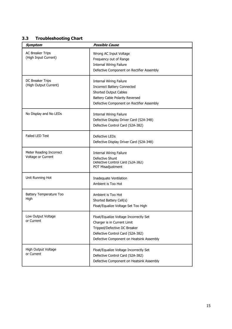
3.3 Troubleshooting Chart
Symptom Possible Cause
Wrong AC Input Voltage
Frequency out of Range
Internal Wiring Failure
Defective Component on Rectifier Assembly
Internal Wiring Failure
Incorrect Battery Connected
Shorted Output Cables
Battery Cable Polarity Reversed
Defective Component on Rectifier Assembly
Internal Wiring Failure
Defective Display Driver Card (S2A-348)
Defective Control Card (S2A-382)
Defective LEDs
Defective Display Driver Card (S2A-348)
Internal Wiring Failure
Defective ShuntDefective Control Card (S2A-382)
POT Misadjustment
Inadequate Ventilation
Ambient is Too Hot
Ambient is Too Hot
Shorted Battery Cell(s)
Float/Equalize Voltage Set Too High
Float/Equalize Voltage Incorrectly Set
Charger is in Current Limit
Tripped/Defective DC Breaker
Defective Control Card (S2A-382)
Defective Component on Heatsink Assembly
Float/Equalize Voltage Incorrectly Set
Defective Control Card (S2A-382)
Defective Component on Heatsink Assembly
Battery Temperature Too High
Low Output Voltage or Current
High Output Voltage
or Current
AC Breaker Trips(High Input Current)
DC Breaker Trips(High Output Current)
No Display and No LEDs
Failed LED Test
Meter Reading Incorrect Voltage or Current
Unit Running Hot

16
Appendix A: ESCR II Specifications
ELECTRICAL
AC InputVoltage range ± 10%
Frequency Range 50/60Hz
DC Output 30, 40 or 50 ADC @ 24 VDC
Output Filtering Less then 500mV RMS, with connected battery
Regulation± 0.5% from no load to full load over the specified input
voltage, frequency and ambient temperature range.
MetersLCD Digital Display
DC Ammeter & DC Voltmeter ± 1% Accuracy
PROTECTION
Current Walk-InThe output current will gradually increase after the
charger is turned on, eliminating surges and overshoot
Current Limit 50 - 110% of the rated DC output current.
AC Breaker AC breaker is standard.
DC Breaker DC breaker is standard.
ENVIROMENTAL
0 to 50˚C (32 to 122˚F), derated to 55˚C
0 to 60˚C (32 to 140˚F), derated to 67˚C (for ZF1 units)
Storage Temperature -40 to 85° C (-40 to 185° F)
Relative Humidity 0 to 95% (non-condensing)
Cooling Convection cooled
Shock
The battery charger in its shipping container withstands shock developed when one edge of the container is
dropped six inches while the opposite edge is resting on the ground, or it is dropped two inches without any physical damage or degradation of the electrical performance.
Vibration
The battery charger in its shipping contained, withstands
vibration encountered in shipping without physical damage or degradation of the electrical performance.
Altitude
This battery charger is capable of operation at altitudes
up to 10,000 feet at an ambient temperature of up to +40° C.
Operating Temperature

17
Appendix B: Manufacturer’s Warranty
All La Marche Manufacturing Co. equipment has been thoroughly tested and found to be in proper operating condition upon shipment from the factory and is warranted to be free from any defect in workmanship and material that may develop within three (3) years from date of purchase.
Any part or parts of the equipment (except fuses, d.c. connectors and other wear-related items) that prove defective within a three (3) year period shall be replaced without charge providing such defect, in our opinion, is due to faulty material or workmanship and not caused by tampering, abuse, misapplication or improper installation.
Should a piece of equipment require repair during the warranty period, the equipment can be returned to the La Marche factory to have the inspection, parts replacements and testing performed by factory personnel. Should it be necessary to return a piece of equipment or parts to the factory, the customer or sales representative must obtain authorization from the factory. If upon inspection at the factory, the defect was due to faulty material or workmanship, all repairs will be made at no cost to the customer during the first three years. Transportation charges or duties shall be borne by purchaser.
In accepting delivery of the equipment, the purchaser assumes full responsibility for proper installation, installation adjustments and service arrangements. Should minor adjustments be required, the local La Marche sales representative should be contacted to provide this service only.
All sales are final. Only standard La Marche units will be considered for return. A 25% restocking fee is charged when return is factory authorized. Special units are not returnable.
In no event shall La Marche Manufacturing Co. have any liability for consequential damages, or loss, damage or expense directly or indirectly arising from the use of the products, or any inability to use them either separately or in combination with other equipment or materials, or from any other cause. In addition, any alterations of equipment made by anyone other than La Marche Manufacturing Co. renders this warranty null and void.
La Marche Manufacturing Co. reserves the right to make revisions in current production of equipment, and assumes no obligation to incorporate these revisions in earlier models.
The failure of La Marche Manufacturing Co. to object to provisions contained in customers' purchase orders or other communications shall not be deemed a waiver of the terms or conditions hereof, nor acceptance of such provisions.
The above warranty is exclusive, supersedes and is in lieu of all other warranties, expressed or implied, including any implied warranty of merchantability or fitness. No person, agent or dealer is authorized to give any warranties on behalf of the Manufacturer, nor to assume for the Manufacturer any other liability in connection with any of its products unless made in writing and signed by an official of the manufacturer.
Appendix C: Document Control and Revision History
Part Number: 125202 Instruction Number: P25-LESCRII-1 Issue ECN: 19669 – 8/12
19783 - 12/12 20488 – 07/14