engine & generator controls installation · pdf fileelectrical connection of engine and...
TRANSCRIPT
BEFORE BEGINNING INSTALLATION OF THIS PRODUCT
Disconnect all electrical power to the machine
Make sure the machine cannot operate during installation
Follow all safety warnings of the machine manufacturer
Read and follow all installation instructions
WARNING
General
Keystart 9620 and 9621 engine control modules provide manual start/stop and automatic fault shutdown protection for generators, pumps and other engine-driven applications.
Operator control of the engine is through a four-way keyswitch, with six LEDs for indication of status and faults – see Front View diagram for details. Electrical connection and circuit board jumper/ potentiometer configuration options are at the rear – see Rear View, Connection and Settings section below.
WARNING: please note differences in rear circuit board configuration links between models manufactured before and after April 2015. Incorrect configuration may result in permanent damage to the Keystart.
Panel Installation Keystart is designed for front-of-panel mounting in a DIN standard 92 x 92 mm (3.6 x 3.6 in.) cut-out. Allow 75mm (3.0 in.) behind the panel front for case depth, keyswitch and cable connection.
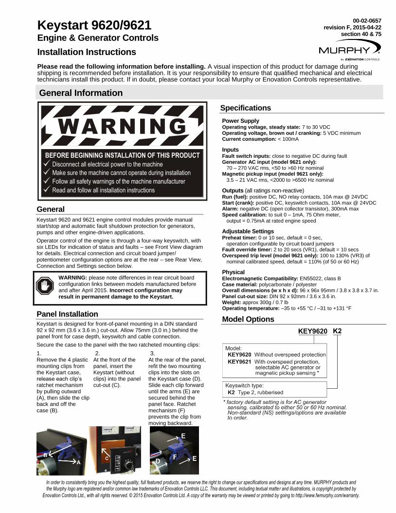
Secure the case to the panel with the two ratcheted mounting clips:
1. 2. 3. Remove the 4 plastic mounting clips from the Keystart case, release each clip’s ratchet mechanism by pulling outward (A), then slide the clip back and off the case (B).
At the front of the panel, insert the Keystart (without clips) into the panel cut-out (C).
At the rear of the panel, refit the two mounting clips into the slots on the Keystart case (D). Slide each clip forward until the arms (E) are secured behind the panel face. Ratchet mechanism (F) prevents the clip from moving backward.
Keystart 9620/9621 Engine & Generator Controls
Installation Instructions
00-02-0657 revision F, 2015-04-22
section 40 & 75
Please read the following information before installing. A visual inspection of this product for damage during shipping is recommended before installation. It is your responsibility to ensure that qualified mechanical and electrical technicians install this product. If in doubt, please contact your local Murphy or Enovation Controls representative.
General Information
Specifications
Power Supply Operating voltage, steady state: 7 to 30 VDC Operating voltage, brown out / cranking: 5 VDC minimum Current consumption: < 100mA
Inputs Fault switch inputs: close to negative DC during fault Generator AC input (model 9621 only): 70 – 270 VAC rms, <50 to >60 Hz nominal Magnetic pickup input (model 9621 only): 3.5 – 21 VAC rms, <2000 to >6500 Hz nominal
Outputs (all ratings non-reactive) Run (fuel): positive DC, NO relay contacts, 10A max @ 24VDC Start (crank): positive DC, keyswitch contacts, 10A max @ 24VDC Alarm: negative DC (open collector transistor), 300mA max Speed calibration: to suit 0 – 1mA, 75 Ohm meter, output = 0.75mA at rated engine speed
Adjustable Settings Preheat timer: 0 or 10 sec, default = 0 sec, operation configurable by circuit board jumpers Fault override timer: 2 to 20 secs (VR1), default = 10 secs Overspeed trip level (model 9621 only): 100 to 130% (VR3) of nominal calibrated speed, default = 110% (of 50 or 60 Hz)
Physical Electromagnetic Compatibility: EN55022, class B Case material: polycarbonate / polyester Overall dimensions (w x h x d): 96 x 96x 95mm / 3.8 x 3.8 x 3.7 in. Panel cut-out size: DIN 92 x 92mm / 3.6 x 3.6 in. Weight: approx 300g / 0.7 lb Operating temperature: –35 to +55 °C / –31 to +131 °F
Model Options
In order to consistently bring you the highest quality, full featured products, we reserve the right to change our specifications and designs at any time. MURPHY products and the Murphy logo are registered and/or common law trademarks of Enovation Controls LLC. This document, including textual matte r and illustrations, is copyright protected by
Enovation Controls Ltd., with all rights reserved. © 2015 Enovation Controls Ltd. A copy of the warranty may be viewed or printed by going to http://www.fwmurphy.com/warranty.

Keystart 9620/9621 installation instructions 00-02-0657 revision F 2015-04-22 2/4
Electrical connection to 0.5 to 1.5 mm² / 16 – 20 AWG panel wiring is by spring-clamp terminals at the rear.
Pre-strip 8 to 10 mm / 0.3 to 0.4 in. of insulation from each wire.
Above each terminal is a square push-button with a diagonal slot. Insert a flat-head screwdriver into the slot (A), then push down to (toward the front of the Keystart) to open the terminal clamp.
Insert the wire into the terminal (B), checking that the insulation is clear of the clamp. Release the screwdriver/spring clamp pressure and check that the wire is secure.
General connection recommendations
Enovation Controls makes several recommendations for the electrical connection of engine and generator controllers.
Minimise controller output load current (i.e. wear and tear, and potential damage) by using slave relays between the controller outputs and high power end devices such as fuel and starter solenoids.
Suppress (at source) electrical interference from panel relay and engine solenoid coils, using flywheel diode or proprietary snubber networks as appropriate.
Use separate routing for AC and DC wiring harnesses.
Use separate wiring for a) connection of battery charger to battery, and b) connection of battery to panel DC supply. Separate wiring will reduce high frequency battery charger output noise on the panel DC power supply.
General Information (cont.)
Front View and Operation
Rear View, Connection and Settings
Electrical Connection
DANGER !HIGH VOLTS
WARNING: DANGER OF INJURY OR DEATH. Keystart 9621 controllers allow connection
of high voltage AC circuits. Before connection, disconnection or handling of these units,
ensure that all AC and DC power supplies are isolated. Connection to or disconnection from
live wiring may also cause damage to the Keystart’s internal components.
Keystart 9620/9621 installation instructions 00-02-0657 revision F 2015-04-22 3/4
Terminal functions
Pin Function
1 2
Run (fuel) output Preheat output
These relay outputs provide control for the engine preheater and (energised to run) fuel / ignition circuits.
The Run output (pin 1) activates immediately on switching the key to the I (RUN) position. The Run output remains active, and the green LED lights, until the operator switches the key to O (STOP) or until the Keystart initiates an automatic fault shutdown.
The Preheat output (pin 2) can be configured to operate in several different modes – see Rear View, Connection and Configuration. The amber LED lights while the Preheat output is active.
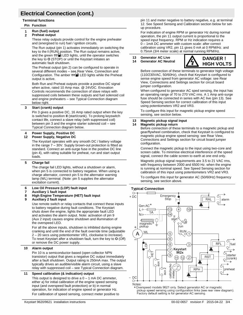
Both Run and Preheat outputs provide a positive DC signal when active, rated 10 Amp max. @ 24VDC. Enovation Controls recommends the connection of slave relays with suppressed coils between these outputs and fuel solenoid coil and engine preheaters – see Typical Connection diagram below right.
3 Start (crank) output
Pin 3 gives a positive DC, 16 Amp rated output when the key is switched to position II (start/crank). To prolong keyswitch contact life, connect a slave relay (with suppressed coil) between pin 3 and the engine starter solenoid coil – see Typical Connection diagram below.
4 12
Power Supply, Positive DC Power Supply, Negative DC
The Keystart operates with any smooth DC / battery voltage in the range 7 – 30V. Supply brown-out protection is fitted as standard. Connect an anti-surge fuse in the positive DC line (pin 4), with rating suitable for preheat, run and start output loads.
5 Charge fail
The charge fail LED lights, without a shutdown or alarm, when pin 5 is connected to battery negative. When using a charge alternator, connect pin 5 to the alternator warning lamp (WL) terminal. (Note: pin 5 supplies the alternator excitation current).
6 7 8 9
Low Oil Pressure (LOP) fault input Auxiliary 1 fault input High Engine Temperature (HET) fault input Auxiliary 2 fault input
Use remote switch or relay contacts that connect these inputs to battery negative during fault conditions. The Keystart shuts down the engine, lights the appropriate fault LED and activates the alarm output. Note: activation of pin 9 (Aux 2 input) causes engine shutdown and illumination of the overspeed LED.
For all the above inputs, shutdown is inhibited during engine cranking and until the end of the fault override time (adjustable 2 – 20 secs using potentiometer VR1, clockwise to increase). To reset Keystart after a shutdown fault, turn the key to O (Off) or remove the DC power supply.
10 Alarm output
Pin 10 is a semiconductor-based (open collector NPN transistor) output that gives a negative DC output immediately after a fault shutdown. Output rating is 250mA max. The output typically drives an audible/visible alarm circuit, using a slave relay with suppressed coil – see Typical Connection diagram.
11 Speed calibration (& indication) output
This output is designed to drive a 0 – 1 mA DC ammeter, either a) for initial calibration of the engine speed sensing input (and overspeed fault protection) or b) in normal operation, for indication of engine speed or generator Hz.
For calibration of speed sensing, connect meter positive to
pin 11 and meter negative to battery negative, e.g. at terminal 12. See Speed Sensing and Calibration section below for set-up procedure.
For indication of engine RPM or generator Hz during normal operation, the pin 11 output current is proportional to the speed input frequency. RPM or Hz indication requires a 0 – 1mA DC ammeter with custom scale: after correct calibration using VR2, pin 11 gives 0 mA at 0 RPM/Hz. and 0.75mA (3/4 meter scale) at normal running RPM/Hz.
13 14
Generator AC Live Generator AC Neutral
DANGER ! HIGH VOLTS
Before connection of these terminals to generator high voltage (110/230VAC, 50/60Hz), check that Keystart is configured to sense engine speed from generator AC voltage: see Rear View, Connections and Settings section for circuit board jumper configuration.
When configured to generator AC sped sensing, the input has an operating range of 70 to 270 VAC rms. A 1 Amp anti-surge fuse should be connected in series with AC live (pin 13). See Speed Sensing section for correct calibration of this input using potentiometers VR2 and VR3.
To configure this input for magnetic pickup engine speed sensing, see section below.
13 14
Magnetic pickup signal input Magnetic pickup return Before connection of these terminals to a magnetic pickup and gear/flywheel combination, check that Keystart is configured to magnetic pickup engine speed sensing: see Rear View, Connections and Settings section for circuit board jumper configuration.
Connect the magnetic pickup to the input using two-core and screen cable. To minimise electrical interference of the speed signal, connect the cable screen to earth at one end only.
Magnetic pickup signal requirements are 3.5 to 21 VAC rms, with frequency between 2000 and 6500 Hz. when the engine is running at nominal speed. See Speed Sensing section for calibration of this input using potentiometers VR2 and VR3.
To configure this input for generator AC (50/60Hz) frequency sensing, see section above.
Typical Connection
Electrical Connection (cont.)

Keystart 9620/9621 installation instructions 00-02-0657 revision F 2015-04-22 4/4
Keystart model 9621 includes a speed sensing input and automatic shutdown protection for engine overspeed faults. Before use, model 9621’s speed input must be correctly configured (using rear circuit-board links) and calibrated (using potentiometers VR2 and VR3).
Selection of speed signal source: rear circuit board links
Rear circuit board jumper links allow configuration of the speed sensing input (terminals 13 and 14) for either high voltage generator AC (the factory default setting) or magnetic pickup signals.
See Rear View, Connection and Settings section above for full details, noting the differences in models pre-/post-Dec 2014. Use small pliers to add or remove the links as required.
Speed calibration Speed calibration is a two stage process:
1) Nominal speed calibration: potentiometer VR2
The factory default setting is for generator AC speed sensing, with standard models for either 50 or 60Hz nominal calibration. To recalibrate for other systems:
Select the speed sensing method (generator AC or magnetic pickup) using links detailed above.
Turn VR2 fully anti-clockwise (sets calibration for maximum nominal frequency).
Connect a 0 – 1mA, 75 Ohm meter between pin 11 and battery negative, as detailed in Electrical Connection above.
Start and run the engine to nominal (normal running) speed.
Turn VR2 clockwise (decreasing the calibration frequency) until the ammeter rises to read 0.75mA.
2) Overspeed setting: potentiometer VR3
VR3 allows adjustment of the overspeed trip point, between approximately 100 and 130% of the nominal speed calibration level (as set using VR2). The VR3 factory default setting is 110% (of either 50 or 60Hz). To adjust the overspeed trip level:
Turn VR3 fully clockwise (to maximum, approx. 130% of nominal)
Start and run the engine. Increase engine speed to the required overspeed/over-frequency trip level.
Turn VR3 slowly anti-clockwise (decreasing the overspeed trip level) until the Keystart shuts down the engine and indicates overspeed.
Where the engine speed cannot be adjusted, or if the speed signal cannot be simulated (e.g. with an adjustable signal generator), an approximate overspeed setting must be made, e.g. a mid-span setting of potentiometer VR3 = approximately 115% of VR2 nominal.
Maintenance and Warranty
The Keystart contains the following replaceable parts:
Document Description
41.70.0157 Spare mounting clips (pack of 4) 76.70.0127 Spare keyswitch (K1 type), inc. key 65.70.0256 Spare keyswitch (K2 type), inc. key 00.00.3235 Spare key (K2 type)
The Keystart series contains no other user-serviceable parts. Maintenance is therefore limited to the following preventative checks:
Check that all electrical connections are secure.
Check that configuration links J1 - J4 are fitted correctly.
Check that the Keystart is securely clamped in the front of panel aperture and kept free from ingress of water or build up of excessive dust or dirt. The front face label and casing may be wiped with a clean, damp cloth. Do not use cleaning solvents.
Each Keystart is supplied with a two-year warranty on materials
and workmanship. In the event of a fault or technical query,
please contact your Murphy or Enovation Controls representative
for technical support.
Speed Sensing and Calibration
ENOVATION CONTROLS CORPORATE HEADQUARTERS 5311 S 122ND EAST AVENUE, TULSA, OK 74146, USA
ENOVATION CONTROLS – SAN ANTONIO OFFICE 5757 FARINON DRIVE, SAN ANTONIO, TX 78249, USA
ENOVATION CONTROLS – HOUSTON OFFICE 105 RANDON DYER RD, ROSENBERG, TX 77471, USA
ENOVATION CONTROLS LTD. – UNITED KINGDOM CHURCH ROAD, LAVERSTOCK, SALISBURY, SP1 1QZ, UK
MURPHY ECONTROLS TECHNOLOGIES – CHINA 77 23RD STREET, HANGZHOU ECONOMIC & TECHNOLOGICAL DEVELOPMENT AREA, HANGZHOU, ZHEIJIANG 310018, CHINA
SALES & SUPPORT, NORTH AMERICA
MURPHY PRODUCTS: PHONE: 918 317 4100 FAX: 918 317 4266 EMAIL: [email protected] WWW.FWMURPHY.COM
ECONTROLS PRODUCTS: PHONE: 210 495 9772 FAX: 210 495 9791 EMAIL: [email protected] WWW.ECONTROLS.COM
MURPHY CONTROL SYSTEMS & SERVICES PHONE: 281 633 4500 FAX: 281 633 4588 EMAIL: [email protected]
MURPHY INDUSTRIAL PANEL DIVISION PHONE: 918 317 4100 FAX: 918 317 4124 EMAIL: [email protected]
SALES & SUPPORT, INTERNATIONAL
EUROPE, MIDDLE EAST & AFRICA PHONE: +44 1722 410055 FAX: +44 1722 410088 EMAIL: [email protected] WWW.FWMURPHY.EU
CHINA PHONE: +86 571 8788 6060 FAX: +86 571 8684 8878 EMAIL: [email protected]
LATIN AMERICA & CARIBBEAN PHONE: +1 918 317 2500 EMAIL: [email protected]
SOUTH KOREA PHONE: +82 70 7951 4100 EMAIL: [email protected]
INDIA PHONE: +91 91581 37633 EMAIL: [email protected]
FM 28221 (Tulsa, OK – USA)
FM 28221 (Rosenberg, TX – USA) FM 620667 (San Antonio, TX – USA) FM 29422 (UK)
FM 523851, TS 589322 (China)