“energy use of condensates in biocel paskov a.s.”€¦ · lifting lugs or trunnions for...
TRANSCRIPT

Scope of supply and conditions of delivery
RFQ_2002_Welded_Tanks_30082012.docx
Page 1 of 14
RFQ 2002 : Complete delivery of welded tanks for the project
“Energy use of condensates in Biocel Paskov a.s.”
SCOPE OF SUPPLY AND CONDITIONS OF DELIVERY
1 SELLER'S SCOPE OF SUPPLY
1.1 Tank 52.09-B11, 52.09-B12, 52.09-B22, 52.09-B13, 52.09-B23, 52.09-B15, 52.09-B14,
The Seller has to ensure the complete and timely supply of all materials and auxiliary materials.
Supplier’s scope of supply includes:
52.09-B11 Buffer Tank 52.09-B12 Neutralization Tank 52.09-B22 Neutralization Tank 52.09-B13 ECSB Reactor Tank 52.09-B23 ECSB Reactor Tank 52.09-B15 Biomass Storage Tank 52.09-B14 Flash Aeration Tank The tanks will be installed in PS 52.09 Anaerobic waste water treatment plant . Tanks will be installed on a concrete foundation outside of building.
Neutralization 52.09-12/22 tanks shall be fabricated in the workshop and delivered as one piece to site. All other tanks will be pre-fabricate in the workshop and finalized on site due to large diameter.
Seller has to pay attention for a proper tank fabrication area in and outside the EUOCBP in accordance to lay out.
The attached drawings for the tanks are the basis for the design and scope of the supply.
In particular, Seller's scope of supply includes:
Detail Engineering as tank drawings, part lists, stress and static calculation Detail Engineering as calculations and drawings for settler support and hold
down system. Complete delivery of tanks, installed on site, tested and ready for operation Assembling and welding of each tank to one piece Complete delivery of support and hold down systems for settlers.

Scope of supply and conditions of delivery
RFQ_2002_Welded_Tanks_30082012.docx
Page 2 of 14
Mounting of settler system in the reactor tanks 52.09 – B13/B23 under supervision of settler supplier (Hydrothane).
On site welding of flanges after mounting of settler system. Erection of the field-erected tanks at job site Tanks shell, bottom, roof Skirt or support structure Nozzles with flanges Stiffener plates for nozzles Bolts, nuts and washers, gaskets Manholes, complete with covers, gaskets, bolts and davits Lifting lugs or trunnions for erection Grounding lugs Nameplate Platforms (as specified) All other parts specified on the drawings Prefabrication, assembling and welding Pickling and passivation of all stainless steel parts incl. all necessary
preventive actions to ensure environmental conditions Surface protection of carbon steel parts Anchor bolts in stainless steel (material A4) Blind flanges, gaskets and bolting material required for hydrostatic testing Scaffolding for fabrication & installation All equipment and devices for prefabrication/fabrication Preparation of area for prefabrication (if necessary) Cranes and trucks
1.1.1 Platforms
Sellers's scope of supply shall contain all service platforms, handrails and stairs, complete with accessories in accordance to standard.
Material
Supports, Handrails, ladders 1.4301 Gratings
All platforms are covered with anti-slip type gratings. The gratings have to be supplied with bending bars. Necessary cut-outs for pipes, cables etc. have to be surrounded with minimum 130 mm high foot protection board before galvanizing. In case of cut-outs no load reduction is allowed. If modifications (e.g. cutting, drilling, welding, etc.) will be done after galvanization the gratings have to be galvanized again.
All gratings have to be fixed at least with four galvanized grating fasteners.
Bearing bars have a minimum dimension of TS 30 / 3 mm. Standard sizes of gratings shall be used. It is not allowed to use quadratic gratings.
Load for main platforms 300 kg/m²
Scope of supply and conditions of delivery
RFQ_2002_Welded_Tanks_30082012.docx
Page 3 of 14
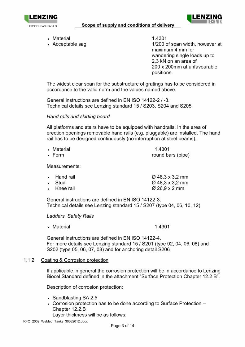
Material 1.4301 Acceptable sag 1/200 of span width, however at
maximum 4 mm for wandering single loads up to 2,3 kN on an area of 200 x 200mm at unfavourable positions.
The widest clear span for the substructure of gratings has to be considered in accordance to the valid norm and the values named above.
General instructions are defined in EN ISO 14122-2 / -3. Technical details see Lenzing standard 15 / S203, S204 and S205
Hand rails and skirting board
All platforms and stairs have to be equipped with handrails. In the area of erection openings removable hand rails (e.g. pluggable) are installed. The hand rail has to be designed continuously (no interruption at steel beams).
Material 1.4301 Form round bars (pipe) Measurements:
Hand rail Ø 48,3 x 3,2 mm Stud Ø 48,3 x 3,2 mm Knee rail Ø 26,9 x 2 mm General instructions are defined in EN ISO 14122-3. Technical details see Lenzing standard 15 / S207 (type 04, 06, 10, 12)
Ladders, Safety Rails
Material 1.4301 General instructions are defined in EN ISO 14122-4. For more details see Lenzing standard 15 / S201 (type 02, 04, 06, 08) and S202 (type 05, 06, 07, 08) and for anchoring detail S206
1.1.2 Coating & Corrosion protection
If applicable in general the corrosion protection will be in accordance to Lenzing Biocel Standard defined in the attachment “Surface Protection Chapter 12.2 B”.
Description of corrosion protection:
Sandblasting SA 2,5 Corrosion protection has to be done according to Surface Protection –
Chapter 12.2.B Layer thickness will be as follows:

Scope of supply and conditions of delivery
RFQ_2002_Welded_Tanks_30082012.docx
Page 4 of 14
- 1 x 70 µm two-component epoxy primer - 1 x 110 µm two-component epoxy intermediate coat with ferrous mica - 1 x 60 µm two-component polyurethane finishing coat
The total nominal thickness of coating system (NDFT) shall amount 240 µm (see DIN EN ISO 12944-5 table A4). Each layer has to be made in a different colour. BUYER will have possibility to go to SELLER’s workshop and make sample measurements of each layer by company Videfkor.
The colour on the top coating shall be declared by LBP. The different strokes with painting shall have different colours.
Defects caused by welding or assembling shall be given the same corrosion protection by as coating described above. Other painting systems are not allowed unless approved by LBP.
Top coat colour
Steel structure / supports RAL6021 Final top coat colour will be fixed before order.
1.2 Installation
Seller's scope of supply shall contain the installation of all tanks, as well as all related co-ordination work. Such installation and work comprise, inter alia:
Erection of tanks and their accessories Erection of platforms, ladders, handrails Provision of all erection materials Provision of scaffolding Provision of all erection tools, including heavy erection equipment (e.g.
cranes, trucks) Supervision of erection, co-ordination of sub-suppliers
1.3 Inspections and Testing
Sellers's scope of supply shall contain the required inspections TÜV and tests for all his supplies as well as all related co-ordination work. Such testing comprises, inter alia:
Inspections at sub-suppliers' premises, if any Visual testing VT 100%

Scope of supply and conditions of delivery
RFQ_2002_Welded_Tanks_30082012.docx
Page 5 of 14
Non-destructive testing NDT 100% Tightness test (water filling) X-ray testing
- T-connections 100% - Longitudinal seams 10%
All other tests and inspections required by code and local regulations All testing instruments and other testing equipment for inspections and tests are to be provided by Seller at his own cost and responsibility.
1.4 Tank Identification
All tanks have to be equipped with a name plate in accordance to LBP requirements, as minimum:
Position number e.g. 52.09-B11 Manufacturer Volume Design temperature Design pressure Max pressure Construction regulation Fluid identity Weight empty Year of fabrication
2 DESIGN, FABRICATION AND ERECTION
2.1 Attached Specifications, Drawings and Data Sheets
Supplier's design of all tanks must comply with the particular specifications, drawings and/or data sheets attached.
All positions of nozzles are preliminary. Final positions of nozzles will be advised at later date during detail engineering.
2.2 Design, Performance and Quality Requirements
2.2.1 Design and fabrication standards
SUPPLIER’s design of the vessel must comply with the requirements of all applicable codes and standards as well as all applicable laws and regulations. In any case the latest edition of the respective standard or code, valid at the date of issue of the purchase order by LBP, applies.
Vessels are designed according to:
Relevant standards are for - All tanks EN 14015 with lower testing amount

Scope of supply and conditions of delivery
RFQ_2002_Welded_Tanks_30082012.docx
Page 6 of 14
(testing acc. to EN 13445-5 group 3b) Eurocode (as EN 1993-4-2, EN 1998-4,….) and related codes and standard Czech laws, regulations and statutes, EN standards Mechanical engineering including manufacturing and erection Static calculation shall consider
- Nature elements according Czech regulations (wind, snow, earth quake, etc.) - Loads caused from pipe supports, service platforms, ladders, cable trays, etc. - Loads from internals - Other loads during erection, supervision, start-up and test operation - Nozzle connection loads
Delivery conditions for flat products made of steels for pressure EN 10028-7, surface 2B respectively 1D
Material certificate according to EN 10204 - 3.1 Tolerances for construction of vessels DIN 28005 and EN ISO 13920 Welding – Basic welded joint details in steel for pressurized components
DIN EN 1708-1; joint penetrations have to be back-welded. Quality levels for imperfections of welding joints will be done according to
DIN EN ISO 5817 – group B Quality requirements for fusion welding of metallic materials - EN ISO 3834-2 Tolerances for welded constructions, dimensions for lengths and angels;
shape and position of welding according to DIN EN ISO 13920 B and F Stainless steel parts are inert gas welded with argon. All stainless steel parts have to be pickled and passivated. To prevent crevice corrosion gaps are not allowed. After pickling welding temper colours are not acceptable. With random video-endoscope test defect free has to be demonstrated by the supplier if necessary.
Before start of on-site welding a welder test, test plate and RT EN 1435B, EN 12517 Class 1 is required.
Surface protection of carbon steel parts shall be provided according to Biocel standard.
2.2.2 LBP Mill Standards
The Supplier is obliged to refer to and use the available LBP Mill Standards whenever they are applicable. A set of the most relevant LBP Mill Standards is enclosed to this RFQ.
2.2.3 Standard of Care
The Supplier agrees to perform all work and services with all reasonable skill, care and diligence and to carry out all his responsibilities in accordance with state-of-the-art techniques and recognised professional standards, in order to ensure personal safety and plant safety of LBP's plant as well as appropriate lifetime of the supplied equipment.

Scope of supply and conditions of delivery
RFQ_2002_Welded_Tanks_30082012.docx
Page 7 of 14
In case that the Supplier realises any error or deficiency, whether technical or legal, in documents or information which are placed at his disposal by LT or LBP, he has to immediately notify LT or LBP, stating the specific details in writing.
2.2.4 Quality Assurance
All Supplier’s work shall be subjected to quality assurance and interdisciplinary quality control techniques presently available at his company.
At the start all involved parties have to do a quality assurance meeting with LBP.
2.2.5 General information
The vessels have to be designed for the maximal pressure/temperature (PS/TS).
The SUPPLIER is required to specify whether a vessel is shop fabricated or field erected. Please observe:
Assembling and welding to one piece shall be preferable done at SUPPLIER’s workshop unless size does not allow transportation in one piece.
In case of field erected vessels, the plates shall be pre-bent and edges shall be prepared for welding at site. Also other prefabrication shall be done in the workshop to the largest extent possibility.
Hydrostatic test for shop fabricated vessels have to be done at SUPPLIER’s workshop. Site fabricated on site.
Accessories for adjusting the shell during field erection are in the scope of supply of the SUPPLIER. These accessories have to be removed before painting, insulation or start-up of the equipment. Locations of removed accessories have to be crack tested.
SUPPLIER has to provide appropriate measures if the weather conditions (low temperature, rain, heavy wind, etc.) for welding at field erection are not acceptable.
Welding factor 0,85 has to be used.
Supporting plates on the vessel for the steel support structure has to be made in stainless steel.
On-site measurement has to be done by the supplier.
All nozzles, manholes, insulation holders, reinforcement and external rings have to be made in stainless steel. Inside reinforcement rings are not allowed.
All equipment has to be equipped with vent and drain nozzles including blind flanges, gaskets and bolting material.
Lifting lugs or trunnions for erection have been provided.

Scope of supply and conditions of delivery
RFQ_2002_Welded_Tanks_30082012.docx
Page 8 of 14
Blind flanges, gaskets and bolting material required for hydrostatic testing is included in the scope of supply.
All testing instruments and other testing equipment for inspections and tests, including mechanical tests, cold / hot tests, and performance test, are to be provided by SUPPLIER at his own cost and responsibility.
After careful cleaning of the vessels or pre-fabricated parts they shall be packed for transportation. All nozzles and other opening will be closed with rubber gaskets and/or wooden covers.
The vessels shall be equipped with wooden saddles for transport. Loose and miscellaneous parts must be packed in separate closed boxes.
2.2.6 Wall thickness
Minimum wall thickness
Shell, bottom 4 mm Roof 4 mm
2.2.7 Nozzles
All nozzles shall be equipped with weld neck flanges PN10 according to DIN EN 1092-1, type 11.
Nozzles DN80 and equal and smaller are equipped with stiffening plates.
Manholes have to be designed according to DIN 28124. A stainless steel davit has to be provided for manholes, blind flanges or covers over 40 kg.
Manholes in horizontal position have to be equipped inside the vessel with a handhold located 300mm above the manhole. If necessary also step supports shall be installed below the manhole. For safety a removable grid on top manhole has to be installed.
Minimum nozzle wall thickness
DN 15 to 80 3 mm DN 100 to 125 4 mm DN 150 to 350 6 mm DN 400 to 600 8 mm DN 600 to 1000 10 mm
Nozzle Loads
Below shown table shall be applied for nozzle loads as minimum load. Detail figures about nozzle forces and loads will be given when appropriate piping drawings and stress calculations are available.

Scope of supply and conditions of delivery
RFQ_2002_Welded_Tanks_30082012.docx
Page 9 of 14
P ML=MN M [N] [Nm] [Nm]
DN 15 247 33 47 DN 20 346 50 71 DN 25 450 68 97 DN 32 601 97 137 DN 40 782 132 187 DN 50 1018 181 256 DN 65 1388 262 370 DN 80 1774 351 497 DN100 2311 482 682 DN125 3010 663 938 DN150 3737 862 1219 DN200 5259 1310 1853 DN250 6731 1822 2577 DN300 8501 2397 3390
Notation
P Radial force [N] ML Longitudinal moment [Nm] MC Tangential moment [Nm] M Moment in sphere [Nm]
2.3 Erection Conditions
The tanks will be implemented into the PS – 52.09 Anaerobic waste water treatment plant . Supplier is responsible to fully observe the existing installations and circumstances.
Furthermore, Supplier has to consider that parallel works will be done at the same time. Disturbances of the plant operation during the erection phase must be avoided
2.3.1 Site Conditions
The design is to be based on the specifications listed below:
Elevation 262 m above sea level
Climate moderate with cold winters
Ambient temperatures: Dry bulb, outdoor -25 °C up to +35 °C Dry bulb, indoor +5 °C up to +35 °C
Annual average pressure 987 hPa
Wind region II, ground category II Wind load 0,60 kN/m²
Scope of supply and conditions of delivery
RFQ_2002_Welded_Tanks_30082012.docx
Page 10 of 14
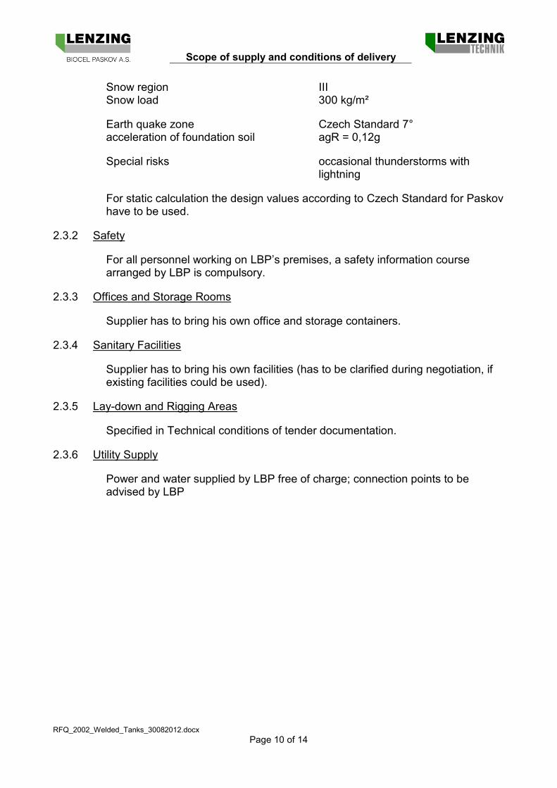
Snow region III Snow load 300 kg/m²
Earth quake zone Czech Standard 7° acceleration of foundation soil agR = 0,12g
Special risks occasional thunderstorms with lightning
For static calculation the design values according to Czech Standard for Paskov have to be used.
2.3.2 Safety
For all personnel working on LBP’s premises, a safety information course arranged by LBP is compulsory.
2.3.3 Offices and Storage Rooms
Supplier has to bring his own office and storage containers.
2.3.4 Sanitary Facilities
Supplier has to bring his own facilities (has to be clarified during negotiation, if existing facilities could be used).
2.3.5 Lay-down and Rigging Areas
Specified in Technical conditions of tender documentation.
2.3.6 Utility Supply
Power and water supplied by LBP free of charge; connection points to be advised by LBP

Scope of supply and conditions of delivery
RFQ_2002_Welded_Tanks_30082012.docx
Page 11 of 14
3 SHIPPING, PACKING AND MARKING INSTRUCTIONS
The delivery is DDP (Incoterms 2000) BIOCEL’s Works Paskov.
Shipping instructions and advice of the dispatch
3.1 Correspondence
Any correspondence and delivery of the subject of the contract are to be sent or advised to the address as follows:
Biocel Paskov a.s. Ing. Pavel Kupka Zahradni 762 CZ – 739 21 Paskov Czech Republic
In case that the shipping instructions from the SUPPLIER are not observed, any extra costs arisen because of a traffic diversion or other reasons are to be paid by him.
The Seller is obliged to advise the dispatch to the LBP 3 days in advance (by fax possibly).
The Seller is obliged to advise the LBP of the dispatch of the goods and documents by fax within two working days after the consignment was handed over to the forwarding agent.
The advice of the dispatch should contain:
Date of the dispatch Place of the dispatch Code No. …............
LBP Contract number (= LBP order and position number) Project number Marking of the goods Value of the consignment Gross and net weights Dimension ( L x W x H ) of each package Total number of packages Total invoice value of each part-shipments Estimated time of arrival at LBP’s works in Paskov Instructions for storage
3.2 Shipping Documents
Of each shipment, the Seller shall issue to LBP following documents:
Customs Invoice in duplicate marked-up with “Shippers invoice declaration”, (replacing the EUR 1 certificate).
Advice Note

Scope of supply and conditions of delivery
RFQ_2002_Welded_Tanks_30082012.docx
Page 12 of 14
Packing List Certificate of Origin Truck Way Bill (The original goes with the consignment) All documents must show Buyers complete contract number.
3.3 Transportation and Storage
Seller’s scope of supply shall contain all transportation, which is necessary for getting his deliveries to the erection site and into their final place in the plant. Transportation and storage comprise, inter alia:
Transportation of all delivered parts to Paskov site Transportation to the erection site Receipt and unloading of arriving deliveries Handling of formalities
4 DOCUMENTATION TO DELIVERY OF WORKS
4.1 General
Documentation packages are to be delivered in six (6) sets of paper copies, A4 holes punched, and in electronic form on disk.
Engineering tools:
Drawings AutoCAD 2010 Lists (data base) MS Office 2003 (Excel) Text documents MS Office 2003 (Word) Each documentation package shall be accompanied by a listing of the documents contained.
Revised documents shall clearly show the modifications made since the previous revision.
Number and delivery of documentation packages
Seller has to transmit each documentation package in the form of paper copies to LBP and Lenzing Technik in due time, so that it arrives at the agreed date.
LBP 5 sets in paper + electronic Lenzing Technik 1 set in paper + electronic Documentation Language
If no special agreement, drawings and documents have to be in English language except operation & maintenance manual in Cz language.

Scope of supply and conditions of delivery
RFQ_2002_Welded_Tanks_30082012.docx
Page 13 of 14
4.2 Design Documentation for Approval (before fabrication release)
Three (3) weeks after execution of agreement on delivery of works the Seller shall supply the following documents:
Quality inspection plan (QIP) Risk analysis and hazard assessment Workshop drawings and part lists Wall thickness calculation Stress and stability calculation Welding and testing plans Detailed fabrication and testing time schedule Workshop drawings and part list for platforms incl. ladders ,handrails aso. Static calculation for platforms Welding procedure specification WPS EN ISO 15609-1 Specification and qualification of welding procedures for metallic materials
WPQR EN ISO 15614-1 (not older than 2 years) Qualification test of welders EN 287-1 Qualification for IWE welding supervision engineer EN 14713 Qualification for NDT-testing EN 473 level 2 For vessels delivered in parts also the documentation for the work executed on site has to be supplied.
4.3 Final documentation (As-Built) - before release for shipment to site
After the hydrostatic test the Supplier shall supply the Final Documentation within three (3) weeks, which has to include all documents and certificates necessary to obtain operating permission for the plant items included in his scope of supply.
As a minimum, the Final Documentation shall contain as-built versions of:
All workshop drawings, calculations, part lists Wall thickness and nozzle calculation Stress and stability calculation Material test certificates 3.1B including welding consumables TÜV Test and inspection reports (welding, visual testing (VT), non destructive
testing (NDT), pressure testing (PT), measurements, etc.) Welder qualification and welding procedure qualification reports according to
code Welding plan Any other certificates or records necessary to prove that the item is
manufactured in full compliance with the requirements of the purchase order and any applicable codes and standards
Material certificates EN 10204 3.1 including welding consumables Static calculations for platforms CE certificate according EN 1090-1 or manufacturer statement Wear and spare part list
Maintenance manuals

Scope of supply and conditions of delivery
RFQ_2002_Welded_Tanks_30082012.docx
Page 14 of 14
Manufacturer declaration
5 GENERAL TERMS AND CONDITIONS
5.1 Terms and Conditions
Terms and Conditions are specified in tender documentation
Abreviations: LT – Lenzing Technik LBP – Lenzing Biocel Paskov LAG – Lenzing AG EUOCBP – Energy use of condensates in Biocel Paskov a.s.