energy star program requirements for large … star lne...energy star program requirements for large...
TRANSCRIPT

ENERGY STAR® Program Requirements
for Large Network Equipment
Partner Commitments
ENERGY STAR Program Requirements for Large Network Equipment – Partner Commitments Page 1 of 3
Following are the terms of the ENERGY STAR Partnership Agreement as it pertains to the manufacture and labeling of ENERGY STAR certified products. The ENERGY STAR Partner must adhere to the following partner commitments:
Certifying Products
1. Comply with current ENERGY STAR Eligibility Criteria, which define performance requirements and test procedures for Large Network Equipment. A list of eligible products and their corresponding Eligibility Criteria can be found at www.energystar.gov/specifications.
2. Prior to associating the ENERGY STAR name or mark with any product, obtain written certification of ENERGY STAR certification from a Certification Body recognized by EPA for Large Network Equipment. As part of this certification process, products must be tested in a laboratory recognized by EPA to perform Large Network Equipment testing. A list of EPA-recognized laboratories and certification bodies can be found at www.energystar.gov/testingandverification.
Using the ENERGY STAR Name and Marks
3. Comply with current ENERGY STAR Identity Guidelines, which define how the ENERGY STAR name and marks may be used. Partner is responsible for adhering to these guidelines and ensuring that its authorized representatives, such as advertising agencies, dealers, and distributors, are also in compliance. The ENERGY STAR Identity Guidelines are available at www.energystar.gov/logouse.
4. Use the ENERGY STAR name and marks only in association with certified products. Partner may not refer to itself as an ENERGY STAR Partner unless at least one product is certified and offered for sale in the U.S. and/or ENERGY STAR partner countries.
5. Provide clear and consistent labeling of ENERGY STAR certified Large Network Equipment. Partner shall adhere to the following product-specific commitments regarding use of the ENERGY STAR certification mark on certified products: 5.1. Partner must use the ENERGY STAR mark in all of the following ways:
5.1.1. The ENERGY STAR mark shall be included on the product specification sheet on the Partner’s website where product information is displayed. This mark shall serve as a hyperlink from the manufacturer’s specification sheet to the ENERGY STAR product website for Large Network Equipment;
5.1.2. The ENERGY STAR mark shall be used to identify certified Large Network Equipment and Large Network Equipment families in electronic and printed marketing and collateral materials, including but not limited to user manuals, product guides, and marketing brochures.
5.2. If additional information about the ENERGY STAR program(s) or other products is provided by the Partner on its website, Partner must comply with the ENERGY STAR Web Linking Policy, which can be found at www.energystar.gov/partners.

ENERGY STAR Program Requirements for Large Network Equipment – Partner Commitments Page 2 of 3
Verifying Ongoing Product Certification
6. Participate in third-party verification testing through a Certification Body recognized by EPA for Large Network Equipment, providing full cooperation and timely responses, EPA/DOE may also, at its discretion, conduct tests on products that are referred to as ENERGY STAR qualified. These products may be obtained on the open market, or voluntarily supplied by Partner at the government’s request.
Providing Information to EPA
7. Provide unit shipment data or other market indicators to EPA annually to assist with creation of ENERGY STAR market penetration estimates, as follows:
7.1. Partner must submit the total number of ENERGY STAR certified Large Network Equipment products shipped in the calendar year or an equivalent measurement as agreed to in advance by EPA and Partner. Partner shall exclude shipments to organizations that rebrand and resell the shipments (unaffiliated private labelers).
7.2. Partner must provide unit shipment data segmented by meaningful product characteristics (e.g., type, capacity, presence of additional functions) as prescribed by EPA.
7.3. Partner must submit unit shipment data for each calendar year to EPA or an EPA-authorized third party, preferably in electronic format, no later than March 1 of the following year.
Submitted unit shipment data will be used by EPA only for program evaluation purposes and will be closely controlled. If requested under the Freedom of Information Act (FOIA), EPA will argue that the data is exempt. Any information used will be masked by EPA so as to protect the confidentiality of the Partner.
8. Report to EPA any attempts by recognized laboratories or Certification Bodies (CBs) to influence testing or certification results or to engage in discriminatory practices.
9. Notify EPA of a change in the designated responsible party or contacts within 30 days using the My ENERGY STAR Account tool (MESA) available at www.energystar.gov/mesa.
Performance for Special Distinction
In order to receive additional recognition and/or support from EPA for its efforts within the Partnership, the ENERGY STAR Partner may consider the following voluntary measures, and should keep EPA informed on the progress of these efforts:
Provide quarterly, written updates to EPA as to the efforts undertaken by Partner to increase availability of ENERGY STAR certified products, and to promote awareness of ENERGY STAR and its message.
Consider energy efficiency improvements in company facilities and pursue benchmarking buildings through the ENERGY STAR Buildings program.
Purchase ENERGY STAR certified products. Revise the company purchasing or procurement specifications to include ENERGY STAR. Provide procurement officials’ contact information to EPA for periodic updates and coordination. Circulate general ENERGY STAR certified product information to employees for use when purchasing products for their homes.
Feature the ENERGY STAR mark(s) on Partner website and other promotional materials. If information concerning ENERGY STAR is provided on the Partner website as specified by the ENERGY STAR Web Linking Policy (available in the Partner Resources section of the ENERGY STAR website), EPA may provide links where appropriate to the Partner website.
Ensure the power management feature is enabled on all ENERGY STAR certified displays and computers in use in company facilities, particularly upon installation and after service is performed.

ENERGY STAR Program Requirements for Large Network Equipment – Partner Commitments Page 3 of 3
Provide general information about the ENERGY STAR program to employees whose jobs are relevant to the development, marketing, sales, and service of current ENERGY STAR certified products.
Provide a simple plan to EPA outlining specific measures Partner plans to undertake beyond the program requirements listed above. By doing so, EPA may be able to coordinate, and communicate Partner’s activities, provide an EPA representative, or include news about the event in the ENERGY STAR newsletter, on the ENERGY STAR website, etc. The plan may be as simple as providing a list of planned activities or milestones of which Partner would like EPA to be aware. For example, activities may include: (1) increasing the availability of ENERGY STAR certified products by converting the entire product line within two years to meet ENERGY STAR guidelines; (2) demonstrating the economic and environmental benefits of energy efficiency through special in-store displays twice a year; (3) providing information to users (via the website and user’s manual) about energy-saving features and operating characteristics of ENERGY STAR certified products; and (4) building awareness of the ENERGY STAR Partnership and brand identity by collaborating with EPA on one print advertorial and one live press event.
Join EPA's SmartWay Transport Partnership to improve the environmental performance of the company's shipping operations. The SmartWay Transport Partnership works with freight carriers, shippers, and other stakeholders in the goods movement industry to reduce fuel consumption, greenhouse gases, and air pollution. For more information on SmartWay, visit www.epa.gov/smartway.
Join EPA’s Green Power Partnership. EPA's Green Power Partnership encourages organizations to buy green power as a way to reduce the environmental impacts associated with traditional fossil fuel-based electricity use. The partnership includes a diverse set of organizations including Fortune 500 companies, small and medium businesses, government institutions as well as a growing number of colleges and universities. For more information on Green Power, visit www.epa.gov/greenpower
EN ENERGY STAR® Product Specification for Large Network Equipment Eligibility Criteria Version 1.0
ENERGY STAR Program Requirements for Large Network Equipment – Eligibility Criteria Page 1 of 10
Following is the Version 1.0 ENERGY STAR product specification for Large Network Equipment. A product shall meet all of the identified criteria if it is to earn the ENERGY STAR.
1 DEFINITIONS
A) Product Classifications:
1) Network Equipment: A device whose primary function is to pass Internet Protocol traffic among various network interfaces/ports.
2) Large Network Equipment (LNE): Network Equipment that is mountable in a Standard Equipment Rack, supports network management protocols (e.g. SNMP) and contains at least one of the following features:
a) Contains more than eleven (11) Physical Network Ports.
b) Total aggregate port throughput of the product is greater than 12 Gb/s
3) Modular Product: An LNE product that accepts Modules, as defined below in 1.(D)(5), modifying the capability of the device.
4) Fixed Product: An LNE product that cannot accept Modules that modify the capability of the device.
B) Product Types:
1) Router: A network device that routes network packets from one logical network to another, along a predefined or dynamically discovered path, based on network layer information embedded in the Network packet header (OSI layer #3).
2) Switch: A network device that delivers packet data frames to specific physical ports on the device, based on the destination address of each frame from the Data Link (OSI layer #2), within a logical network.
3) Security Appliance: A stand-alone network device whose primary function is to protect the network from unwanted traffic (e.g. secure tunnel and firewall appliances). This includes products whose primary function is to provide virtual private network (VPN) services.
4) Access Point Controller: A network device whose primary function is to manage wireless local area network (WLAN) traffic through one or more wireless access point devices.
C) Product Characteristics:
1) Processor Managed Product: An LNE product whose management is handled through a distinct co-management processor within the product itself that has independent control over the LNE product.
2) Network Managed Product: An LNE product that is not Processor Managed, where management of the product is handled through processing power provided by a separate device within the network to which it is connected.
3) Stackable Product: A product, which supports the ability to join multiple discrete products of similar type to form a single larger autonomous functioning unit.

ENERGY STAR Program Requirements for Large Network Equipment – Eligibility Criteria Page 2 of 10
D) LNE Components:
1) Power Supply Unit (PSU): A device that converts ac or dc input power to one or more dc power outputs for the purpose of powering an LNE product. An LNE product’s PSU must be self-contained and physically separable from the motherboard and must connect to the system via a removable or hard-wired electrical connection.
A. Ac-Dc Power Supply: A PSU that converts line-voltage ac input power into one or more dc power outputs for the purpose of powering an LNE product.
B. Dc-Dc Power Supply: A PSU that converts line-voltage dc input power to one or more dc outputs for the purpose of powering an LNE product. For purposes of this specification, a dc-dc converter (also known as a voltage regulator) that is internal to an LNE product and is used to convert a low voltage dc (e.g., 12 V dc) into other dc power outputs for use by the LNE product’s components is not considered a dc-dc power supply.
C. Single-output Power Supply: A PSU that is designed to deliver the majority of its rated output power to one primary dc output for the purpose of powering an LNE product. Single-output PSUs may offer one or more standby outputs that remain active whenever connected to an input power source. For purposes of this specification, the total rated power output from any additional PSU outputs that are not primary and standby outputs shall be no greater than 20 watts. PSUs that offer multiple outputs at the same voltage as the primary output are considered single-output PSUs unless those outputs (1) are generated from separate converters or have separate output rectification stages, or (2) have independent current limits.
D. Multi-output Power Supply: A PSU that is designed to deliver the majority of its rated output power to more than one primary dc output for the purpose of powering an LNE product. Multi-output PSUs may offer one or more standby outputs that remain active whenever connected to an input power source. For purposes of this specification, the total rated power output from any additional PSU outputs that are not primary and standby outputs is greater than or equal to 20 watts.
2) Standard Equipment Rack: An equipment enclosure commonly seen in data centers or managed facilities and intended to house a variety of information technology equipment. Front panel width is typically 19 inches (482.6 mm). Standard equipment racks are defined by EIA-310, IEC 60297, or DIN 41494.
3) Modular Chassis: An equipment enclosure used in a modular LNE product that houses all the components of the product together in one place (e.g. PSUs, backplane, modules).
4) Backplane: A circuit board within the chassis of a modular LNE product into which line cards or modules are inserted to allow communication between the various connected modules.
5) Module: A plug in device, not used alone, which can add/change the type of network connections, increase/decrease the number of ports, and add/remove additional functionality for a product. Modules include but are not limited to line cards, port adapters, and network adapters. Modules do not include pluggable transceivers (e.g. SFP, SFP+, XFP) or modular power supplies.
6) Processor: The logic circuitry that responds to and processes the basic instructions that drive an LNE product. For purposes of this specification, a processor is a central processing unit (CPU) which can be used to provide basic function and/or management function.
E) Other Enterprise and Datacenter Information Technology Equipment:
1) Small Network Equipment (SNE): Network Equipment that is intended to serve users in either small networks or a subset of a large network. SNE includes a) all Network Equipment with integral wireless capability and b) other Network Equipment meeting all of the following criteria:
i) Designed for stationary operation

ENERGY STAR Program Requirements for Large Network Equipment – Eligibility Criteria Page 3 of 10
ii) Contains no more than eleven (11) wired Physical Network Ports; and
iii) Primary configuration for operation outside of standard equipment racks.
2) Computer Server: A computer that provides services and manages networked resources for client devices (e.g., desktop computers, notebook computers, thin clients, wireless devices, PDAs, IP telephones, other computer servers and other network devices). A computer server is sold through enterprise channels for use in data centers and office/corporate environments. A computer server is primarily accessed via network connections, versus directly-connected user input devices such as a keyboard or mouse. For purposes of this specification, a product must meet all of the following criteria to be considered a computer server:
i) is marketed and sold as a Computer Server;
ii) is designed for and listed as supporting computer server operating systems (OS) and/or hypervisors;
iii) is targeted to run user-installed applications typically, but not exclusively, enterprise in nature;
iv) provides support for error-correcting code (ECC) and/or buffered memory (including both buffered DIMMs and buffered on board (BOB) configurations)
v) is packaged and sold with one or more ac-dc or dc-dc power supplies; and
vi) is designed such that all processors have access to shared system memory and are visible to a single OS or hypervisor.
3) Storage Product: A fully-functional storage system that supplies data storage services to clients and devices attached directly or through a network. Components and subsystems that are an integral part of the storage product architecture (e.g., to provide internal communications between controllers and disks) are considered to be part of the storage product. In contrast, components that are normally associated with a storage environment at the data center level (e.g., devices required for operation of an external SAN) are not considered to be part of the storage product. A storage product may be composed of integrated storage controllers, storage devices, embedded network elements, software, and other devices. For purposes of this specification, a storage product is a unique configuration of one or more SKUs, sold and marketed to the end user as a Storage Product.
4) Storage Networking Products: Products whose primary purpose is the transfer of data between computers systems and storage products. This includes products that use typical storage networking protocols (e.g. Fibre Channel), as well as those that support IP based storage traffic such as iSCSI capable networking products.
5) Uninterruptible Power Supply (UPS): Combination of convertors, switches, and energy storage devices (such as batteries) constituting a power system for maintaining continuity of load power in case of input power failure.
6) Digital Subscriber Line Access Multiplexer (DSLAM): A network device that connects multiple digital subscriber line (DSL) interfaces to a backbone network that in turn connects to a larger service provider network.
7) Cable Modem Termination System (CMTS): A network device that connects multiple cable television (CATV) interfaces to a backbone network that in turn connects to a larger service provider network. Note that CATV connections are often also used to transfer IP traffic.
8) Network Caching Device: A network device connected to a network that caches content from a remote source that allows connected devices on the downstream network faster subsequent access by later serving the cached content to the downstream devices rather than content accessed directly from the original source.
9) Load Balancing Device: A network device connected to a network that distributes network traffic across several downstream devices. These products allow increased capacity and

ENERGY STAR Program Requirements for Large Network Equipment – Eligibility Criteria Page 4 of 10
reliability of data transfer over the network.
F) Operational Power States:
1) Active State: The operating state where the product is carrying out work in response to prior or concurrent external requests.
2) Idle State: The operating state where the product is capable of carrying out work, but is not actively transferring data.
G) Additional Terms:
1) Physical Network Port: An integrated physical connection point primarily intended to accept IP or similar traffic via a cable. Fiber-optic connections are considered Physical Network Ports for the purposes of this specification.
a) Uplink Port: A port designated for transferring consolidated data traffic from multiple devices or downstream networks attached to the downlink ports to an upstream network or device.
b) Downlink Port: A port designated for distributing data from the consolidated uplink port to a single device or downstream network.
2) Energy Efficient Ethernet (EEE): A technology which enables reduced power consumption of Ethernet interfaces during times of low data throughput. Defined in Clause 78 of IEEE 802.3 (originally specified in IEEE 802.3az).
3) Power over Ethernet (PoE): A technology that enables transfer of electrical power, along with data, to network end point devices through an Ethernet cable. PoE is defined in Clause 33 of IEEE 802.3 (originally specified in IEEE 802.3af and IEEE 802.3at). The PoE specification defines two types of equipment:
a) Type 1: Powered devices up to 13.0 watts
b) Type 2: Powered devices up to 25.5 watts
H) Product Family: A group of models/configurations that share a set of common attributes that are variations on a basic design.
1) Common Product Family Attributes for Modular Products: A set of features common to all models/configurations within a modular product family. All models/configurations within a modular product family must share the following:
a) Be from the same model line or machine type; and
b) Share the same mechanical and electrical designs in the chassis with only superficial mechanical differences to enable a design to support a variety of module options.
2) Product Family Tested Product Configurations:
a) Minimum Power Configuration: The product configuration that includes the combination of components including modules, power supplies, and other associated processing and power support hardware that generates the least possible energy consumption within a product family.
b) Maximum Power Configuration: The product configuration that includes the combination of components including modules, power supplies, and other associated processing and power support hardware that generates the greatest possible energy consumption within a product family.
c) Typical Configuration: A product configuration that lies between the minimum and maximum configurations that is representative of a product with high volumes sales. Product families containing a single product shall be represented by that configuration.

ENERGY STAR Program Requirements for Large Network Equipment – Eligibility Criteria Page 5 of 10
2 SCOPE
2.1 Included Products
2.1.1 Products that meet the definition of Large Network Equipment in Section 1 of this document are eligible for ENERGY STAR certification under this specification. Products explicitly excluded from Version 1.0 are identified in Section 2.2.
2.2 Excluded Products
2.2.1 Products that are covered under other ENERGY STAR product specifications are not eligible for certification under this specification. The list of specifications currently in effect can be found at www.energystar.gov/specifications.
2.2.2 Products that contain greater than four Physical Network Ports that have 40Gb/s or higher link rate capability.
2.2.3 The following products are not eligible for certification under this specification:
i. Small Network Equipment;
ii. Computer Servers, including blade switches sold within a Blade Server configuration;
iii. Storage Products, including Blade Storage;
iv. Storage Networking Products;
v. Security Appliances;
vi. Access Point Controllers;
vii. DSLAM/CMTS equipment;
viii. Network Caching Devices; and
ix. Load Balancing Devices.
3 CERTIFICATION CRITERIA
3.1 Significant Digits and Rounding
3.1.1 All calculations shall be carried out with directly measured (unrounded) values.
3.1.2 Unless otherwise specified in this specification, compliance with specification limits shall be evaluated using directly measured or calculated values without any benefit from rounding.
3.1.3 Directly measured or calculated values that are submitted for reporting on the ENERGY STAR website shall be rounded to the nearest significant digit as expressed in the corresponding specification limit.
3.2 Power Supply Requirements
3.2.1 Power supply test data and test reports from testing entities recognized by EPA to perform power supply testing shall be accepted for the purpose of certifying the ENERGY STAR product.

ENERGY STAR Program Requirements for Large Network Equipment – Eligibility Criteria Page 6 of 10
3.2.2 Power Supply Efficiency Criteria: Power Supplies used in products eligible under this specification must meet the following requirements when tested using the Generalized Internal Power Supply Efficiency Test Protocol, Rev. 6.6 (available at www.efficientpowersupplies.org). Power Supply data generated using Rev. 6.4.2, 6.4.3, or 6.5 are acceptable provided the test was conducted prior to the effective date of Version 1.0 of this specification.
i. Fixed LNE Products: To certify for ENERGY STAR, a fixed LNE product must be configured with only PSUs that meet or exceed the applicable efficiency requirements specified in Table 2 prior to shipment.
ii. Modular LNE Products: To certify for ENERGY STAR, a modular LNE product shipped with a chassis must be configured such that all PSUs supplying power to the chassis meet or exceed the applicable efficiency requirements specified in Table 2 prior to shipment.
Table 2: Efficiency Requirements for PSUs
Power Supply Type Rated Output Power 10% Load
20% Load
50% Load
100% Load
Multi-output
All Output Levels N/A 85% 88% 85%
Single-output
All Output Levels 80% 88% 92% 88%
3.2.3 Power Supply Power Factor Criteria: Ac-Dc Power Supplies used in products eligible under this specification must meet the following requirements when tested using the Generalized Internal Power Supply Efficiency Test Protocol, Rev. 6.6 (available at www.efficientpowersupplies.org). Power Supply data generated using Rev. 6.4.2, 6.4.3, or 6.5 are acceptable provided the test was conducted prior to the effective date of Version 1.0.
i. Fixed LNE Products: To certify for ENERGY STAR, a fixed LNE product must be configured so that all Ac-Dc PSUs within the product meet or exceed the applicable power factor requirements specified in Table 3 prior to shipment, under all loading conditions for which output power is greater than or equal to 75 watts. Partners are required to measure and report PSU power factor under loading conditions of less than 75 watts, though no minimum power factor requirements apply.
ii. Modular LNE Products: To certify for ENERGY STAR, a modular LNE product shipped with a chassis must be configured such that all Ac-Dc PSUs supplying power to the chassis meet or exceed the applicable power factor requirements specified in Table 3 prior to shipment, under all loading conditions for which output power is greater than or equal to 75 watts. Partners are required to measure and report PSU power factor under loading conditions of less than 75 watts, though no minimum power factor requirements apply.

ENERGY STAR Program Requirements for Large Network Equipment – Eligibility Criteria Page 7 of 10
Table 3: Power Factor Requirements for Ac-Dc PSUs
Power Supply Type Rated Output Power 10% Load
20% Load
50% Load
100% Load
Multi-output All Output Ratings N/A 0.80 0.90 0.95
Single-output
Output Rating ≤ 500 W N/A 0.80 0.90 0.95
Output Rating > 500 W
and
Output Rating ≤ 1,000 W
0.65 0.80 0.90 0.95
Output Rating > 1,000 watts
0.80 0.90 0.90 0.95
3.3 Energy Efficiency Feature Requirements
3.3.1 To certify for ENERGY STAR, an LNE product must have the following features enabled in its as-shipped configuration, implemented as specified:
i. Remote Port Administration: An LNE product must provide the end-user with the ability to conduct remote administration of individual physical network ports.
ii. Adaptive Active Cooling: Primary components of an LNE product must utilize adaptive cooling technologies that reduce the energy consumed by the cooling technology in proportion to the current cooling needs of the LNE product. (e.g., reduction of variable speed fan or blower speeds at lower ambient air temperature). This requirement is not applicable to devices that employ passive cooling.
iii. Energy Efficient Ethernet: All copper-based physical network ports in an LNE product must be compliant with IEEE 802.3 Clause 78.
3.4 Active State Efficiency Criteria for all LNE Products
3.4.1 EPA is pursuing this approach to active state evaluation to encourage further testing of the energy efficiency of LNE products. EPA will evaluate this data when considering active state efficiency levels in Version 2.0 of the specification. Efficiency data will be measured and disclosed in a consistent manner and is provided along with the hardware and software characteristics of each system. Thus, this reporting approach will assist manufacturers in differentiating the efficiency of their products and purchasers interested in buying efficient products.
3.4.2 Active State Data Reporting: To certify for ENERGY STAR, an LNE product or LNE Product Family must be submitted for certification with the following information disclosed in full and in the context of the complete Active State efficiency rating test report:
i. Full power and performance shall be measured and reported, both in certification materials and as required in Section 4 for each applicable configuration within the product family as defined in Section 1.H)2) above.
ENERGY STAR Program Requirements for Large Network Equipment – Eligibility Criteria Page 8 of 10
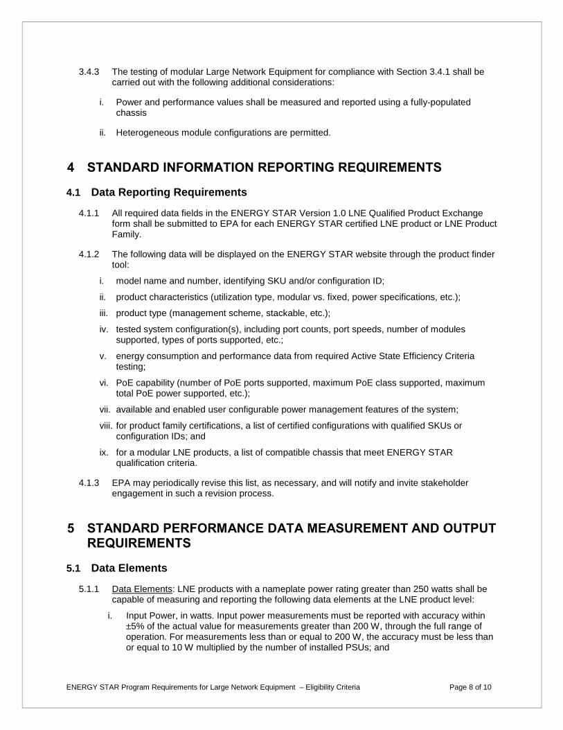
3.4.3 The testing of modular Large Network Equipment for compliance with Section 3.4.1 shall be carried out with the following additional considerations:
i. Power and performance values shall be measured and reported using a fully-populated chassis
ii. Heterogeneous module configurations are permitted.
4 STANDARD INFORMATION REPORTING REQUIREMENTS
4.1 Data Reporting Requirements
4.1.1 All required data fields in the ENERGY STAR Version 1.0 LNE Qualified Product Exchange form shall be submitted to EPA for each ENERGY STAR certified LNE product or LNE Product Family.
4.1.2 The following data will be displayed on the ENERGY STAR website through the product finder tool:
i. model name and number, identifying SKU and/or configuration ID;
ii. product characteristics (utilization type, modular vs. fixed, power specifications, etc.);
iii. product type (management scheme, stackable, etc.);
iv. tested system configuration(s), including port counts, port speeds, number of modules supported, types of ports supported, etc.;
v. energy consumption and performance data from required Active State Efficiency Criteria testing;
vi. PoE capability (number of PoE ports supported, maximum PoE class supported, maximum total PoE power supported, etc.);
vii. available and enabled user configurable power management features of the system;
viii. for product family certifications, a list of certified configurations with qualified SKUs or configuration IDs; and
ix. for a modular LNE products, a list of compatible chassis that meet ENERGY STAR qualification criteria.
4.1.3 EPA may periodically revise this list, as necessary, and will notify and invite stakeholder engagement in such a revision process.
5 STANDARD PERFORMANCE DATA MEASUREMENT AND OUTPUT REQUIREMENTS
5.1 Data Elements
5.1.1 Data Elements: LNE products with a nameplate power rating greater than 250 watts shall be capable of measuring and reporting the following data elements at the LNE product level:
i. Input Power, in watts. Input power measurements must be reported with accuracy within ±5% of the actual value for measurements greater than 200 W, through the full range of operation. For measurements less than or equal to 200 W, the accuracy must be less than or equal to 10 W multiplied by the number of installed PSUs; and

ENERGY STAR Program Requirements for Large Network Equipment – Eligibility Criteria Page 9 of 10
ii. Inlet Air Temperature, in degrees Celsius, with accuracy of ± 2°C.
5.1.2 Reporting Implementation:
i. Data shall be made available in a published or user-accessible format that is readable by third-party, non-proprietary management systems;
ii. Data shall be made available to end users and third-party management systems over a standard network connection;
iii. Data shall be made available via embedded components or add-in devices that are packaged with the LNE product (e.g., a service processor, embedded power or thermal meter or other out-of-band technology, iPDU, or pre-installed OS);
5.1.3 Sampling Requirements:
i. Input power: Input power measurements must be sampled internally to the LNE product at a rate of greater than or equal to 1 measurement per contiguous 10-second period.
ii. Inlet air temperature (optional): Inlet air temperature measurements must be sampled internally to the LNE product at a rate of greater than or equal to 1 measurement every 10 seconds.
iii. Timestamping: Systems that implement time stamping of environmental data shall sample internally to the LNE product data at a rate of greater than or equal to 1 measurement every 30 seconds.
iv. Management Software: All sampled measurements shall be made available to external management software either via an on-demand pull method, or via a coordinated push method. In either case the system’s management software is responsible for establishing the data delivery time scale while the LNE product is responsible to assuring data delivered meets the above sampling and currency requirements.
5.1.4 Documentation Requirements: The following information shall be included in the data submission:
i. Guaranteed accuracy levels for power and temperature measurements, and
ii. The time period used for data averaging (if present).
5.1.5 Use of iPDUs: Section 5.1 may be satisfied using iPDUs. In order to satisfy the Data Elements requirement, an iPDU must:
i. Meet all requirements for accuracy, sampling, and data reporting;
ii. Be made available for sale and delivery with certified ENERGY STAR LNE products by appearing on the manufacturer’s website and/or in marketing material where information on the LNE product is displayed.
6 TESTING
6.1 Test Methods
6.1.1 Manufacturers may select whether to test product with a half-port or full-port configuration for ENERGY STAR certification purposes. The testing configuration used for certification purposes will be noted in the Qualified Product Exchange form and displayed on the ENERGY STAR website.

ENERGY STAR Program Requirements for Large Network Equipment – Eligibility Criteria Page 10 of 10
Table 1: Test Methods for ENERGY STAR Certification
Product Type Test Method
All ENERGY STAR Test Method for Large Network Equipment (Rev. December-2015)
6.2 Number of Units Required for Testing
6.2.1 Representative Models shall be selected for testing per the following requirements:
i. For certification of an individual product configuration, the unique configuration that is intended to be marketed and labeled as ENERGY STAR is considered the Representative Model.
ii. For certification of a product family of all product types, one product configuration for each of the required configurations defined in Section 1.H)2) within the family are considered Representative Models. All such representative models shall have the same Common Product Family Attributes as defined in 1.H).
6.3 International Market Certification
6.3.1 Products shall be tested for certification at the relevant input voltage/frequency combination for each market in which they will be sold and promoted as ENERGY STAR.
7 EFFECTIVE DATE
7.1.1 Effective Date: The Version 1.0 ENERGY STAR Large Network Equipment specification shall take effect on March 1, 2016. To certify for ENERGY STAR, a product model shall meet the ENERGY STAR specification in effect on the model’s date of manufacture. The date of manufacture is specific to each unit and is the date on which a unit is considered to be completely assembled.
7.1.2 Future Specification Revisions: EPA reserves the right to change this specification should technological and/or market changes affect its usefulness to consumers, industry, or the environment. In keeping with current policy, revisions to the specification are arrived at through stakeholder discussions. In the event of a specification revision, please note that the ENERGY STAR certification is not automatically granted for the life of a product model.
8 CONSIDERATIONS FOR FUTURE REVISIONS
8.1.1 Product Scope: EPA will investigate expanding the scope to include additional product types that are not covered in Version 1.0, as appropriate.
8.1.2 Active State Efficiency Criteria: EPA will investigate the product data generated through Version 1.0 certification to support setting active levels in Version 2.0 of this specification wherever possible.

ENERGY STAR® Program Requirements Product Specification for Large Network Equipment Test Method Rev. Jan-2016
ENERGY STAR Program Requirements for Large Network Equipment – Test Method (Rev. Jan-2016) Page 1 of 13
1 OVERVIEW
The following test method shall be used for determining product compliance with requirements in the ENERGY STAR Eligibility Criteria for Large Network Equipment (LNE).
2 APPLICABILITY
The following test method is applicable to all eligible products covered by the scope as defined in Section 2 of the ENERGY STAR Eligibility Criteria for Large Network Equipment, but test requirements are dependent upon the feature set of the product under evaluation. The following guidelines shall be used to determine the applicability of each section of this document:
One or both procedures in Section 6 shall be conducted on eligible products that are fixed products.
The procedures in Section 7 shall be conducted on eligible products that are modular products.
3 DEFINITIONS
Unless otherwise specified, all terms used in this document are consistent with the definitions in the ENERGY STAR Large Network Equipment Specification.
A) Abbreviations and Units:
1) ac: Alternating current
2) ATIS: Alliance for Telecommunications Industry Solutions
3) bps: Bits per second
4) C: Celsius
5) dc: Direct current
6) FCS: Frame check sequence
7) Gbps: Gigabits per second
8) Hz: Hertz
9) IEEE: Institute of Electrical and Electronics Engineers
10) IMIX: Internet mix
11) IP: Internet protocol
12) LNE: Large network equipment
13) MUT: Module under test
14) NDR: Non-drop rate
15) PDU: Power distribution unit

ENERGY STAR Program Requirements for Large Network Equipment – Test Method (Rev. Jan-2016) Page 2 of 13
16) PSU: Power supply unit
17) RMS: Root mean square
18) SFD: Start of frame delimiter
19) UPS: Uninterruptible power supply
20) UUT: Unit under test
21) V: Volts
22) VLU: Very low utilization
23) W: Watt
B) Definitions:
1) High-Speed Port: A physical network Ethernet port that has a highest operable line-rate of at least 10 gigabits per second (Gbps).
2) Internet Mix (IMIX) Traffic: A stateless traffic profile that contains a mixture of frame sizes statistically similar to a composition observed in the Internet1.
3) Maximum Non-Drop Rate (NDR): The highest observed system throughput, measured in bits per second (bps), at which all data packets received by the unit under test (UUT) are processed and correctly transmitted.
4) System Throughput: The sum of the data link bits processed by the UUT per second in the egress direction, including frame preamble, Start Frame Delimiter (SFD), Frame Check Sequence (FCS), and minimum interpacket gap.
5) System Utilization: The system throughput expressed as a percentage of the system’s measured NDR.
6) Traffic Profile: The statistical distribution of the size/type of the data sent through the UUT.
4 TEST SETUP
A) Input Power: Input power for alternating current (ac) LNE shall be as specified in Table 1 and Table 2.
Input power for direct current (dc) LNE shall be as specified in Table 3. The input power frequency for
ac LNE shall be as specified in Table 4.
1 For further information regarding IMIX, refer to Spirent Communications – Test Methodology Journal: IMIX (Internet Mix) Journal, March 2006.

ENERGY STAR Program Requirements for Large Network Equipment – Test Method (Rev. Jan-2016) Page 3 of 13
Table 1: Input Power Requirements for Ac-powered Products with Nameplate Rated Power Less Than 1500 Watts (W)
Product Type Supply Voltage
Voltage Tolerance
Maximum Total Harmonic Distortion
Ac single-phase powered LNE
115 volts (V) ac
230 V ac +/- 1.0%
2.0%, up to and including the 13th
harmonic Ac three-phase powered LNE
208 V ac
400 Vac
Table 2: Input Power Requirements for Ac-powered Products with Nameplate Rated Power Greater Than or Equal to 1500 W
Product Type Supply Voltage
Voltage Tolerance
Maximum Total Harmonic Distortion
Ac single-phase powered LNE
115 V ac
230 V ac
+/- 4.0% 5.0%, up to and
including the 13th harmonic Ac three-phase
powered LNE
208 V ac
400 Vac
Table 3: Input Power Requirements for Dc-powered Products
Product Type Supply Voltage
Voltage Tolerance
Dc powered LNE rated for -48 V dc
-53 V dc +/- 2.0 V

ENERGY STAR Program Requirements for Large Network Equipment – Test Method (Rev. Jan-2016) Page 4 of 13
Table 4: Input Power Frequency Requirements for Ac-powered Products
Supply Voltage
Frequency Frequency Tolerance
115 V ac 60 Hertz
(Hz)
+/-1.0%
230 V ac 50 Hz or
60 Hz
208 V ac, Three-phase
60 Hz
400 V ac, Three-phase
50 Hz or 60 Hz
B) Ambient Temperature: The ambient temperature in front of the main airflow inlet of the UUT during all power measurement tests shall be greater than 22.0° Celsius (C) and less than 28.0° C.
1) Temperature Measurement Location and Accuracy: Temperature must be measured no more than 2 meters in front of (upwind of) an airflow inlet of the UUT and reported by the sensor with an overall accuracy of ± 0.5 °C or better.
C) Relative Humidity: Relative humidity shall be within 15% and 80%.
D) Power Meter: Power meters shall possess the following attributes:
1) Reporting and Measurement Units:
a) If the UUT is a dc powered LNE, the power meter shall report power, voltage, and current.
b) If the UUT is an ac powered LNE, the power meter shall report true root mean square (RMS) power, voltage, current, and power factor.
2) Calibration: The meter shall have been calibrated within a year of the test date, by a standard traceable to National Institute of Standards and Technology [USA] or a counterpart national metrology institute in other countries.
3) Crest Factor (ac powered LNE only): An available current crest factor of 3 or more at its rated range value. For power meters that do not specify the current crest factor, the power meter must be capable of measuring an amperage spike of at least 3 times the maximum amperage measured during any 1 second sample.
4) Minimum Bandwidth of Input Circuitry: 80.0 kHz.
5) Minimum Digitizing Sample Rate: 40.0 kHz.
6) Minimum Resolution:
a) 0.01 W for measurement values less than 10 W;
b) 0.1 W for measurement values from 10 W to 100 W; and
c) 1.0 W for measurement values greater than 100 W.
7) Measurement Accuracy: Power measurements shall be reported by the power meter with an overall accuracy of 1% or better for all measured power values.
E) Network Test Equipment (Test Equipment): The Test Equipment used for Section 6 and Section 7 must comply with the following requirements:

ENERGY STAR Program Requirements for Large Network Equipment – Test Method (Rev. Jan-2016) Page 5 of 13
1) Number of Ports: The Test Equipment shall have at least one port for each port required to be connected to a port on the UUT, as stated in Sections 5.1.B) and 5.1.C). Each connected port on the Test Equipment shall be capable of sending and receiving data to and from the UUT at the highest operable line-rate standard corresponding to the connected port on the UUT.
2) Traffic Generation: The Test Equipment must be capable of generating traffic that complies with the requirements in Section 5.1.A)9).
5 TEST CONDUCT
5.1 UUT and Test Equipment Configuration for Variable Load Testing
All testing performed in Section 6 and Section 7 shall adhere to the requirements provided in the
Alliance for Telecommunications Industry Solutions (ATIS)-0600015.03.2013 standard unless
otherwise specified in this document. All testing performed in Section 6 and Section 7 shall be
conducted as follows:
A) Configuration Requirements for All Products:
1) As-shipped Condition: Products shall be tested in their “as-shipped” configuration, which includes
both hardware configuration and system settings, unless otherwise specified in this test method.
a) LNE Requiring Initial Configuration: If the UUT cannot be tested in its “as-shipped” condition
without additional initial configuration, then the UUT shall be configured according to the
instructions provided in the UUT’s user manual. Any supporting materials (e.g., configuration
files) that are included with the UUT or publicly available may be used if required for correct
UUT functionality.
b) Mid-test UUT Reconfiguration: The UUT shall be configured prior to running the test
procedures in Section 6 or Section 7. No reconfiguration of the UUT shall occur following the
commencement of the procedures in Section 6 or Section 7, unless otherwise specified in
this test method.
2) Measurement Location: All power measurements shall be taken at a point between the ac or dc
power source and the UUT. No uninterruptible power supply (UPS) units may be connected
between the power meter and the UUT.
3) Air Flow Management: Any airflow directly surrounding the UUT during testing shall only be
generated by fans or cooling devices that are standard components of the UUT.
4) Power Supply Units (PSUs): All installed PSUs included with the UUT must be operational and
connected to an appropriate power source, unless otherwise specified in this test method.
a) UUTs with Multiple PSUs: If the UUT has more than one PSU, then any method may be used
to aggregate the power so long as the method used does not introduce a measurement error
greater than 1% of the total measured power.
5) System Management Ports: Any port on the UUT that does not pass traffic, and is solely intended
for device management may be connected as instructed by the manufacturer during testing. If no
manufacturer instruction is provided, system management ports shall be disconnected during
testing.
6) Non-Ethernet Ports: Non-Ethernet data ports shall be connected, not necessarily to the Test
Equipment that generates test traffic, and are not required to pass test traffic. Any traffic passed
by non-Ethernet ports shall not be included in throughput measurements.

ENERGY STAR Program Requirements for Large Network Equipment – Test Method (Rev. Jan-2016) Page 6 of 13
7) I/O and Network Connection: UUT Ethernet ports shall be connected as indicated in Sections
5.1.B) and 5.1.C). All Ethernet ports connected to the Test Equipment shall be ready to pass test
traffic for the entirety of the testing performed in Section 6 and Section 7.
8) Energy Efficient Ethernet (EEE): If the UUT has ports that provide EEE2, the UUT shall be connected to network ports that also support EEE. This can be done either by having the traffic source provide the EEE ports, or placing an intermediate network device between the traffic source and UUT.
9) Traffic Generation: The traffic generated by the Test Equipment for Section 6 and Section 7 must comply with the following requirements:
a) Packet Format: The traffic shall be formatted as Internet Protocol (IP) version 4 (IPv43) with randomized IPv4 data field values. The IPv4 packets shall be transported using Ethernet4.
b) Generated Packet Size Statistical Distribution: The traffic shall consist of packet sizes whose generation frequency is statistically described by the Simple IMIX distribution, defined in Table 5.
c) Idle-link Period Distribution: All traffic shall be generated so that the same interpacket gap separates each transmitted Ethernet packet. In other words, there should be a fixed spacing in time between Ethernet frames. However, frames shall not be sent to all ports simultaneously (i.e. the fixed spacing in time should not occur simultaneously on all ports).
Table 5: Simple IMIX Packet Distribution5
IP Packet Size
(Bytes)
Ethernet Frame Size6
(Bytes)
Proportion of Total Generated
IP Packets
Proportion of Total Generated Ethernet
Packet Throughput7
40 64 7 parts
(~58.33%) ~12.83%
576 594 4 parts
(~33.33%) ~53.60%
1500 1518 1 part
(~8.33%) ~33.57%
2 As defined in Clause 78 of Institute of Electrical and Electronics Engineers (IEEE) 802.3 (originally specified in IEEE 802.3az). 3 “Internet Protocol”. Sep 1981. RFC 791. 4 As defined in IEEE 802.3. 5 “Table D.1: Simple IMIX”, Annex D: IMIX Traffic, ATIS – 0600015.03.2013 6 Ethernet frame sizes do not include preamble, SFD, or minimum interpacket gap. 7 Throughput is based on the listed Ethernet frame size plus 7-byte preamble, 1-byte SFD, and 12-byte minimum interpacket gap per transmitted packet.
ENERGY STAR Program Requirements for Large Network Equipment – Test Method (Rev. Jan-2016) Page 7 of 13
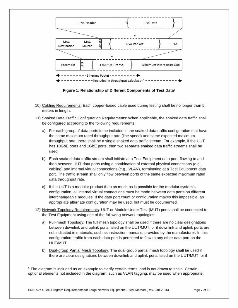
Figure 1: Relationship of Different Components of Test Data8
10) Cabling Requirements: Each copper-based cable used during testing shall be no longer than 5
meters in length.
11) Snaked Data Traffic Configuration Requirements: When applicable, the snaked data traffic shall
be configured according to the following requirements:
a) For each group of data ports to be included in the snaked data traffic configuration that have
the same maximum rated throughput rate (line speed) and same expected maximum
throughput rate, there shall be a single snaked data traffic stream. For example, if the UUT
has 10GbE ports and 1GbE ports, then two separate snaked data traffic streams shall be
used.
b) Each snaked data traffic stream shall initiate at a Test Equipment data port, flowing to and
then between UUT data ports using a combination of external physical connections (e.g.,
cabling) and internal virtual connections (e.g., VLAN), terminating at a Test Equipment data
port. The traffic stream shall only flow between ports of the same expected maximum rated
data throughput rate.
c) If the UUT is a modular product then as much as is possible for the modular system’s
configuration, all internal virtual connections must be made between data ports on different
interchangeable modules. If the data port count or configuration makes this impossible, an
appropriate alternate configuration may be used, but must be documented.
12) Network Topology Requirements: UUT or Module Under Test (MUT) ports shall be connected to
the Test Equipment using one of the following network topologies:
a) Full-mesh Topology: The full mesh topology shall be used if there are no clear designations
between downlink and uplink ports listed on the UUT/MUT, or if downlink and uplink ports are
not indicated in materials, such as instruction manuals, provided by the manufacturer. In this
configuration, traffic from each data port is permitted to flow to any other data port on the
UUT/MUT.
b) Dual-group Partial Mesh Topology: The dual-group partial mesh topology shall be used if
there are clear designations between downlink and uplink ports listed on the UUT/MUT, or if
8 The diagram is included as an example to clarify certain terms, and is not drawn to scale. Certain optional elements not included in the diagram, such as VLAN tagging, may be used when appropriate.
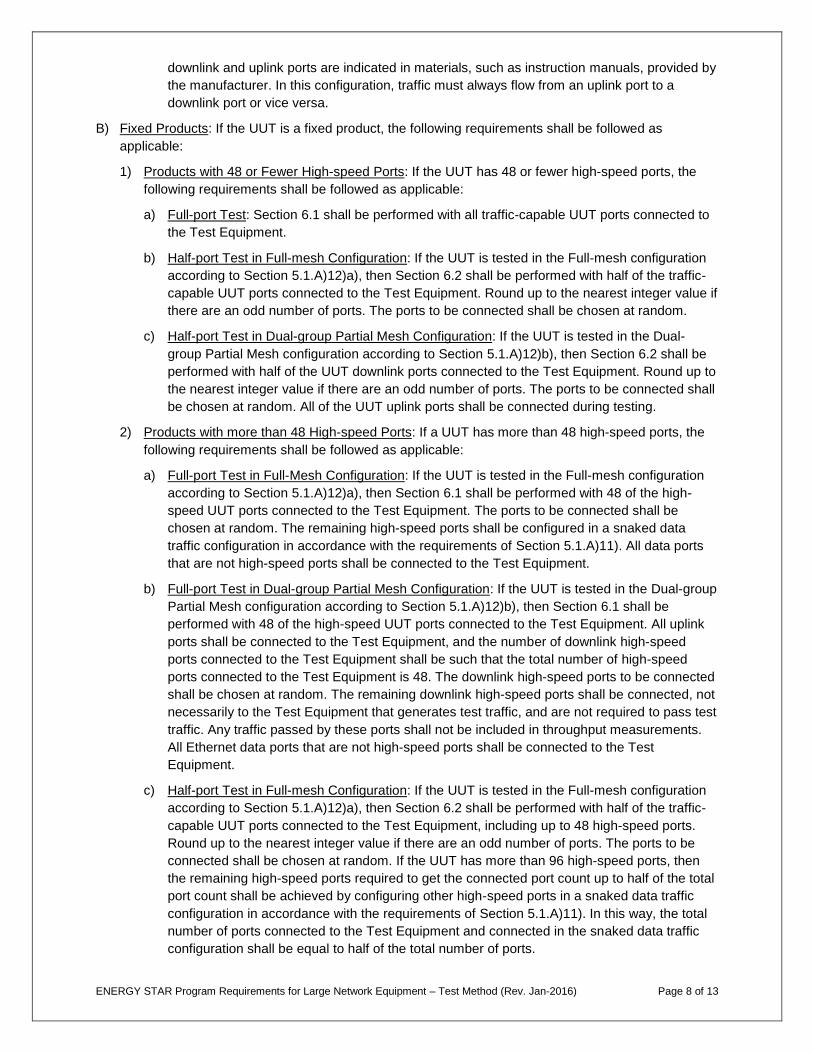
ENERGY STAR Program Requirements for Large Network Equipment – Test Method (Rev. Jan-2016) Page 8 of 13
downlink and uplink ports are indicated in materials, such as instruction manuals, provided by
the manufacturer. In this configuration, traffic must always flow from an uplink port to a
downlink port or vice versa.
B) Fixed Products: If the UUT is a fixed product, the following requirements shall be followed as
applicable:
1) Products with 48 or Fewer High-speed Ports: If the UUT has 48 or fewer high-speed ports, the
following requirements shall be followed as applicable:
a) Full-port Test: Section 6.1 shall be performed with all traffic-capable UUT ports connected to
the Test Equipment.
b) Half-port Test in Full-mesh Configuration: If the UUT is tested in the Full-mesh configuration
according to Section 5.1.A)12)a), then Section 6.2 shall be performed with half of the traffic-
capable UUT ports connected to the Test Equipment. Round up to the nearest integer value if
there are an odd number of ports. The ports to be connected shall be chosen at random.
c) Half-port Test in Dual-group Partial Mesh Configuration: If the UUT is tested in the Dual-
group Partial Mesh configuration according to Section 5.1.A)12)b), then Section 6.2 shall be
performed with half of the UUT downlink ports connected to the Test Equipment. Round up to
the nearest integer value if there are an odd number of ports. The ports to be connected shall
be chosen at random. All of the UUT uplink ports shall be connected during testing.
2) Products with more than 48 High-speed Ports: If a UUT has more than 48 high-speed ports, the
following requirements shall be followed as applicable:
a) Full-port Test in Full-Mesh Configuration: If the UUT is tested in the Full-mesh configuration
according to Section 5.1.A)12)a), then Section 6.1 shall be performed with 48 of the high-
speed UUT ports connected to the Test Equipment. The ports to be connected shall be
chosen at random. The remaining high-speed ports shall be configured in a snaked data
traffic configuration in accordance with the requirements of Section 5.1.A)11). All data ports
that are not high-speed ports shall be connected to the Test Equipment.
b) Full-port Test in Dual-group Partial Mesh Configuration: If the UUT is tested in the Dual-group
Partial Mesh configuration according to Section 5.1.A)12)b), then Section 6.1 shall be
performed with 48 of the high-speed UUT ports connected to the Test Equipment. All uplink
ports shall be connected to the Test Equipment, and the number of downlink high-speed
ports connected to the Test Equipment shall be such that the total number of high-speed
ports connected to the Test Equipment is 48. The downlink high-speed ports to be connected
shall be chosen at random. The remaining downlink high-speed ports shall be connected, not
necessarily to the Test Equipment that generates test traffic, and are not required to pass test
traffic. Any traffic passed by these ports shall not be included in throughput measurements.
All Ethernet data ports that are not high-speed ports shall be connected to the Test
Equipment.
c) Half-port Test in Full-mesh Configuration: If the UUT is tested in the Full-mesh configuration
according to Section 5.1.A)12)a), then Section 6.2 shall be performed with half of the traffic-
capable UUT ports connected to the Test Equipment, including up to 48 high-speed ports.
Round up to the nearest integer value if there are an odd number of ports. The ports to be
connected shall be chosen at random. If the UUT has more than 96 high-speed ports, then
the remaining high-speed ports required to get the connected port count up to half of the total
port count shall be achieved by configuring other high-speed ports in a snaked data traffic
configuration in accordance with the requirements of Section 5.1.A)11). In this way, the total
number of ports connected to the Test Equipment and connected in the snaked data traffic
configuration shall be equal to half of the total number of ports.
ENERGY STAR Program Requirements for Large Network Equipment – Test Method (Rev. Jan-2016) Page 9 of 13
d) Half-port Test in Dual-group Partial Mesh Configuration: If the UUT is tested in the Dual-
group Partial Mesh configuration according to Section 5.1.A)12)b), then Section 6.2 shall be
performed with all uplink ports and half of the downlink ports connected to the Test
Equipment. Round up to the nearest integer value if there are an odd number of ports. The
ports to be connected shall be chosen at random. If the number of high-speed ports (all
uplink plus half of the downlink) exceeds 48, the number of downlink high-speed ports
connected to the Test Equipment shall be reduced so that the total number of high-speed
ports connected to the Test Equipment is 48. If the number of downlink ports connected to
the Test Equipment is less than half of the total number of downlink ports, then the remaining
high-speed ports required to get the connected downlink port count up to half of the total
downlink port count shall be achieved by shall connecting downlink ports, not necessarily to
the Test Equipment that generates test traffic, but these ports are not required to pass test
traffic. Any traffic passed by these ports shall not be included in throughput measurements.
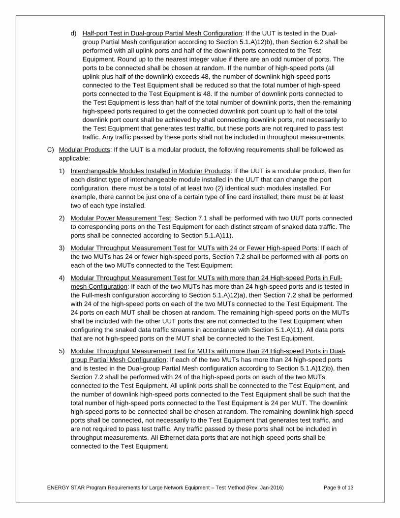
C) Modular Products: If the UUT is a modular product, the following requirements shall be followed as
applicable:
1) Interchangeable Modules Installed in Modular Products: If the UUT is a modular product, then for
each distinct type of interchangeable module installed in the UUT that can change the port
configuration, there must be a total of at least two (2) identical such modules installed. For
example, there cannot be just one of a certain type of line card installed; there must be at least
two of each type installed.
2) Modular Power Measurement Test: Section 7.1 shall be performed with two UUT ports connected
to corresponding ports on the Test Equipment for each distinct stream of snaked data traffic. The
ports shall be connected according to Section 5.1.A)11).
3) Modular Throughput Measurement Test for MUTs with 24 or Fewer High-speed Ports: If each of
the two MUTs has 24 or fewer high-speed ports, Section 7.2 shall be performed with all ports on
each of the two MUTs connected to the Test Equipment.
4) Modular Throughput Measurement Test for MUTs with more than 24 High-speed Ports in Full-
mesh Configuration: If each of the two MUTs has more than 24 high-speed ports and is tested in
the Full-mesh configuration according to Section 5.1.A)12)a), then Section 7.2 shall be performed
with 24 of the high-speed ports on each of the two MUTs connected to the Test Equipment. The
24 ports on each MUT shall be chosen at random. The remaining high-speed ports on the MUTs
shall be included with the other UUT ports that are not connected to the Test Equipment when
configuring the snaked data traffic streams in accordance with Section 5.1.A)11). All data ports
that are not high-speed ports on the MUT shall be connected to the Test Equipment.
5) Modular Throughput Measurement Test for MUTs with more than 24 High-speed Ports in Dual-
group Partial Mesh Configuration: If each of the two MUTs has more than 24 high-speed ports
and is tested in the Dual-group Partial Mesh configuration according to Section 5.1.A)12)b), then
Section 7.2 shall be performed with 24 of the high-speed ports on each of the two MUTs
connected to the Test Equipment. All uplink ports shall be connected to the Test Equipment, and
the number of downlink high-speed ports connected to the Test Equipment shall be such that the
total number of high-speed ports connected to the Test Equipment is 24 per MUT. The downlink
high-speed ports to be connected shall be chosen at random. The remaining downlink high-speed
ports shall be connected, not necessarily to the Test Equipment that generates test traffic, and
are not required to pass test traffic. Any traffic passed by these ports shall not be included in
throughput measurements. All Ethernet data ports that are not high-speed ports shall be
connected to the Test Equipment.
ENERGY STAR Program Requirements for Large Network Equipment – Test Method (Rev. Jan-2016) Page 10 of 13
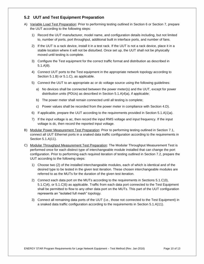
5.2 UUT and Test Equipment Preparation
A) Variable Load Test Preparation: Prior to performing testing outlined in Section 6 or Section 7, prepare
the UUT according to the following steps:
1) Record the UUT manufacturer, model name, and configuration details including, but not limited
to, number of ports, port throughput, additional built in interface ports, and number of fans.
2) If the UUT is a rack device, install it in a test rack. If the UUT is not a rack device, place it in a
stable location where it will not be disturbed. Once set up, the UUT shall not be physically
moved until testing is complete.
3) Configure the Test equipment for the correct traffic format and distribution as described in
5.1.A)9).
4) Connect UUT ports to the Test equipment in the appropriate network topology according to
Section 5.1.B) or 5.1.C), as applicable.
5) Connect the UUT to an appropriate ac or dc voltage source using the following guidelines:
a) No devices shall be connected between the power meter(s) and the UUT, except for power
distribution units (PDUs) as described in Section 5.1.A)4)a), if applicable;
b) The power meter shall remain connected until all testing is complete;
c) Power values shall be recorded from the power meter in compliance with Section 4.D).
6) If applicable, prepare the UUT according to the requirements provided in Section 5.1.A)1)a).
7) If the input voltage is ac, then record the input RMS voltage and input frequency. If the input
voltage is dc, then record the reported input voltage.
B) Modular Power Measurement Test Preparation: Prior to performing testing outlined in Section 7.1,
connect all UUT Ethernet ports in a snaked data traffic configuration according to the requirements in
Section 5.1.A)11).
C) Modular Throughput Measurement Test Preparation: The Modular Throughput Measurement Test is
performed once for each distinct type of interchangeable module installed that can change the port
configuration. Prior to performing each required iteration of testing outlined in Section 7.2, prepare the
UUT according to the following steps:
1) Choose two (2) of the installed interchangeable modules, each of which is identical and of the
desired type to be tested in the given test iteration. These chosen interchangeable modules are
referred to as the MUTs for the duration of the given test iteration.
2) Connect each data port on the MUTs according to the requirements in Sections 5.1.C)3),
5.1.C)4), or 5.1.C)5) as applicable. Traffic from each data port connected to the Test Equipment
shall be permitted to flow to any other data port on the MUTs. This part of the UUT configuration
represents an “isolated full mesh” topology.
3) Connect all remaining data ports of the UUT (i.e., those not connected to the Test Equipment) in
a snaked data traffic configuration according to the requirements in Section 5.1.A)11).
ENERGY STAR Program Requirements for Large Network Equipment – Test Method (Rev. Jan-2016) Page 11 of 13
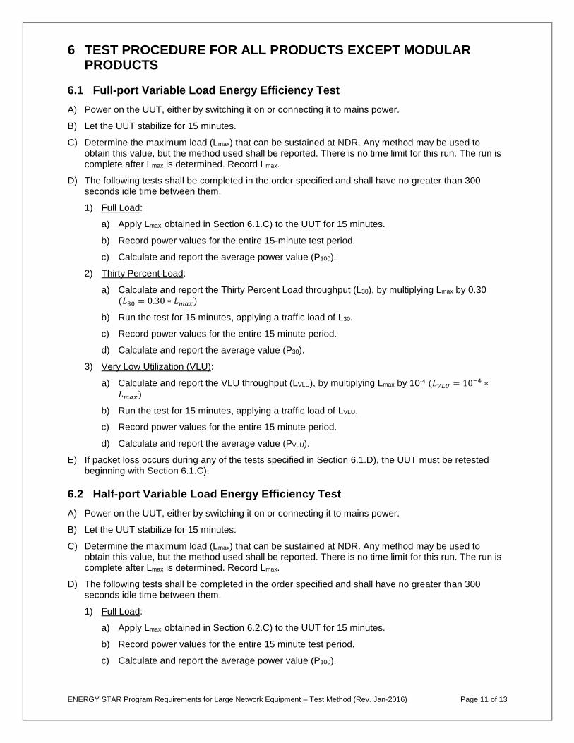
6 TEST PROCEDURE FOR ALL PRODUCTS EXCEPT MODULAR PRODUCTS
6.1 Full-port Variable Load Energy Efficiency Test
A) Power on the UUT, either by switching it on or connecting it to mains power.
B) Let the UUT stabilize for 15 minutes.
C) Determine the maximum load (Lmax) that can be sustained at NDR. Any method may be used to obtain this value, but the method used shall be reported. There is no time limit for this run. The run is complete after Lmax is determined. Record Lmax.
D) The following tests shall be completed in the order specified and shall have no greater than 300 seconds idle time between them.
1) Full Load:
a) Apply Lmax, obtained in Section 6.1.C) to the UUT for 15 minutes.
b) Record power values for the entire 15-minute test period.
c) Calculate and report the average power value (P100).
2) Thirty Percent Load:
a) Calculate and report the Thirty Percent Load throughput (L30), by multiplying Lmax by 0.30 (𝐿30 = 0.30 ∗ 𝐿𝑚𝑎𝑥)
b) Run the test for 15 minutes, applying a traffic load of L30.
c) Record power values for the entire 15 minute period.
d) Calculate and report the average value (P30).
3) Very Low Utilization (VLU):
a) Calculate and report the VLU throughput (LVLU), by multiplying Lmax by 10-4 (𝐿𝑉𝐿𝑈 = 10−4 ∗𝐿𝑚𝑎𝑥)
b) Run the test for 15 minutes, applying a traffic load of LVLU.
c) Record power values for the entire 15 minute period.
d) Calculate and report the average value (PVLU).
E) If packet loss occurs during any of the tests specified in Section 6.1.D), the UUT must be retested beginning with Section 6.1.C).
6.2 Half-port Variable Load Energy Efficiency Test
A) Power on the UUT, either by switching it on or connecting it to mains power.
B) Let the UUT stabilize for 15 minutes.
C) Determine the maximum load (Lmax) that can be sustained at NDR. Any method may be used to obtain this value, but the method used shall be reported. There is no time limit for this run. The run is complete after Lmax is determined. Record Lmax.
D) The following tests shall be completed in the order specified and shall have no greater than 300 seconds idle time between them.
1) Full Load:
a) Apply Lmax, obtained in Section 6.2.C) to the UUT for 15 minutes.
b) Record power values for the entire 15 minute test period.
c) Calculate and report the average power value (P100).
ENERGY STAR Program Requirements for Large Network Equipment – Test Method (Rev. Jan-2016) Page 12 of 13
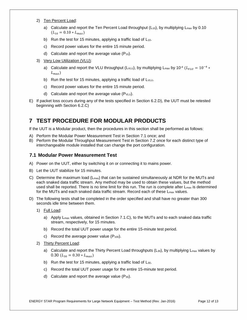
2) Ten Percent Load:
a) Calculate and report the Ten Percent Load throughput (L10), by multiplying Lmax by 0.10 (𝐿10 = 0.10 ∗ 𝐿𝑚𝑎𝑥)
b) Run the test for 15 minutes, applying a traffic load of L10.
c) Record power values for the entire 15 minute period.
d) Calculate and report the average value (P10).
3) Very Low Utilization (VLU):
a) Calculate and report the VLU throughput (LVLU), by multiplying Lmax by 10-4 (𝐿𝑉𝐿𝑈 = 10−4 ∗𝐿𝑚𝑎𝑥)
b) Run the test for 15 minutes, applying a traffic load of LVLU.
c) Record power values for the entire 15 minute period.
d) Calculate and report the average value (PVLU).
E) If packet loss occurs during any of the tests specified in Section 6.2.D), the UUT must be retested beginning with Section 6.2.C)
7 TEST PROCEDURE FOR MODULAR PRODUCTS
If the UUT is a Modular product, then the procedures in this section shall be performed as follows:
A) Perform the Modular Power Measurement Test in Section 7.1 once; and B) Perform the Modular Throughput Measurement Test in Section 7.2 once for each distinct type of
interchangeable module installed that can change the port configuration.
7.1 Modular Power Measurement Test
A) Power on the UUT, either by switching it on or connecting it to mains power.
B) Let the UUT stabilize for 15 minutes.
C) Determine the maximum load (Lmax) that can be sustained simultaneously at NDR for the MUTs and each snaked data traffic stream. Any method may be used to obtain these values, but the method used shall be reported. There is no time limit for this run. The run is complete after Lmax is determined for the MUTs and each snaked data traffic stream. Record each of these Lmax values.
D) The following tests shall be completed in the order specified and shall have no greater than 300 seconds idle time between them.
1) Full Load:
a) Apply Lmax values, obtained in Section 7.1.C), to the MUTs and to each snaked data traffic stream, respectively, for 15 minutes.
b) Record the total UUT power usage for the entire 15-minute test period.
c) Record the average power value (P100).
2) Thirty Percent Load:
a) Calculate and report the Thirty Percent Load throughputs (L30), by multiplying Lmax values by 0.30 (𝐿30 = 0.30 ∗ 𝐿𝑚𝑎𝑥)
b) Run the test for 15 minutes, applying a traffic load of L30.
c) Record the total UUT power usage for the entire 15-minute test period.
d) Calculate and report the average value (P30).

ENERGY STAR Program Requirements for Large Network Equipment – Test Method (Rev. Jan-2016) Page 13 of 13
3) Very Low Utilization (VLU):
a) Calculate and report the VLU throughputs (LVLU), by multiplying Lmax values by 10-4 (𝐿𝑉𝐿𝑈 =10−4 ∗ 𝐿𝑚𝑎𝑥)
b) Run the test for 15 minutes, applying a traffic load of LVLU.
c) Record total UUT power usage for the entire 15-minute period.
d) Calculate and report the average value (PVLU).
E) If packet loss occurs during any of the tests specified in Section 7.1.D), the UUT must be retested beginning with Section 7.1.C).
7.2 Modular Throughput Measurement Test
A) Power on the UUT, either by switching it on or connecting it to mains power.
B) Let the UUT stabilize for 15 minutes.
C) Determine the maximum load (Lmax) that can be sustained at NDR for the MUTs and each snaked data traffic stream. Any method may be used to obtain these values, but the method used shall be reported. There is no time limit for this run. The run is complete after Lmax is determined for the MUTs and each snaked data traffic stream. Record the combined Lmax for the MUTs.
D) For each distinct type of interchangeable module installed in the UUT, reconfigure the UUT according to Section 5.2.C) and repeat step 7.2.C) until the maximum load of each distinct type of installed interchangeable module has been measured.
E) Calculate and report the aggregate system maximum throughput (Ltot) using the following equation:
𝐿𝑡𝑜𝑡 = ∑𝑁𝑘 ∙𝐿𝑚𝑎𝑥_𝑘
2
𝑁𝑡𝑜𝑡
𝑘=1
Where:
𝐿𝑡𝑜𝑡 is the UUT aggregate system maximum throughput
𝑁𝑡𝑜𝑡 is the total number of distinct types of interchangeable modules installed in the UUT
𝑁𝑘 is the total number of interchangeable modules installed in the UUT of type, “k”
𝐿𝑚𝑎𝑥_𝑘 is the maximum load for the two interchangeable modules of type, “k”, measured in Section 7.2.
8 REFERENCES
A) Alliance for Telecommunications Industry Solutions (ATIS) – 0600015.03.2013 Energy Efficiency for Telecommunication Equipment: Methodology for Measurement and Reporting for Router and Ethernet Switch Products
B) Spirent Communications – Test Methodology Journal: IMIX (Internet Mix) Journal, March 2006.
C) IEEE 802.3-2012: IEEE Standard for Ethernet.