energy smart housing manual - chapter 7 (pdf ...€¦ · the contents of this chapter outline the...
TRANSCRIPT

The contents of this chapter outline the benefits of insulation, how insulation performance ismeasured and types of insulation products. Guidelines are provided for insulation selection andinstallation.
Insulation benefitsInsulation is the most effective way to improve the energy efficiency of a home. Insulation of thebuilding envelope helps keep heat in during the winter, but lets heat out during summer to improvecomfort and save energy.
Insulating a home can save 45–55% of heating and cooling energy. Table 7.1 shows the savingson heating and cooling energy when insulation is installed.
Table 7.1: Typical energy savings due to insulation
EXTENT OF INSULATION HEATING COOLING HEATING AND COOLING
Ceiling only (added R2.5) 15–25% 30–45% 20–30%
Ceiling (added R2.5) 40–50% 40–55% 40–50%and walls (added R1.0)
Ceiling (added R2.5), 45–55% 35–50% 45–55%walls (added R1.0) and floor (added R1.0)
Benefits of insulation:
comfort is improved year-round;
it reduces the cost of heating and cooling by over 40%;
it pays for itself in around five to six years;
there is less need for heating and cooling which saves non-renewable resources and reducesgreenhouse gas emissions;
it virtually eliminates condensation on walls and ceilings; and
some insulation materials can also be used for sound proofing.
ENERGY SMART HOUSING MANUAL42
INSULATION
CHAPTER 7

How insulation worksAn uninsulated home is subject to considerable winter heat losses and summer heat gains (see figure 7.1).
All materials allow a measure of heat to pass through them. Some, such as metal, glass or air,allow heat to pass through more easily. Others, including animal fur or wool, thick clothing andstill air, are much more resistant to heat flow, and are referred to as insulators.
The term ‘insulation’ refers to materials which provide substantial resistance to heat flow. When these materials are installed in the ceiling, walls, and floors of a building, heat flow into and out of the building is reduced, and the need for heating and cooling is minimised.
Although ceilings and walls may be insulated, heat loss will still occur in winter if there are largeareas of unprotected glass or through fixed wall vents and gaps and cracks around external doorsand windows. Appropriate internal window coverings (e.g. lined drapes with pelmets) and draughtproofing are vital to complement insulation.
Insulation should always be coupled with appropriate shading of windows and adequateventilation in summer. Without shading, heat entering the home through the windows will betrapped inside by the insulation and cause discomfort.
Understanding heat transferThere are three ways in which heat is transferred—radiation, convection and conduction.
A warm plasterboard ceiling in winter provides an example of these different methods of heat transfer.
RADIATIONRadiation is the direct heat which can be sensed by the skin, such as the sun’s rays or the heatfrom an open fire. Heat (infra-red) radiation which is emitted from the surface of hot objects,travels in straight lines to cooler objects. With radiant heat transfer, heat is emitted from the warmplasterboard ceiling to cooler roof tiles on a cold night (see figure 7.2).
43© Sustainable Energy Authority Victoria 2002
ceiling25–35%
windows10–20%
air leakage15–25%
floor10–20%
walls15–25%
WINTER LOSSES
walls15–25%
ceiling25–35%
windows25–35%
air leakage5–15%
SUMMER GAINS
Figure 7.1: Heat flow without insulation
cold night temperature
plasterboard is warm warm indoor temperature
roof surface is cold
radiates heat to colder surface
Figure 7.2: Radiant heat transfer

CONVECTIONConvection transfers heat through the movement of gases or liquids. For instance, when air iswarmed, it rises and is replaced by cooler air. This creates a cycle or convection current capableof transferring heat. With convective heat transfer, the warm layer of air above the ceiling risesand comes into contact with the cold roof surface, cools by losing some heat to the roof material,then falls to the plasterboard where the process repeats itself (see figure 7.3).
CONDUCTIONConduction is heat transfer from warm to cooler areas within a material, or between two materialstouching each other. Gases, such as air, do not conduct heat very well. Solids, particularly metal,conduct heat much more readily. With conductive heat transfer, heat inside the home warms thebottom layer of plasterboard ceiling which transfers heat to the next layer, and so on (see figure 7.4).
Principles of insulationResistance to heat flow is achieved by the use of either bulk insulation or reflective insulation,which work in different ways.
BULK INSULATIONBulk insulation traps millions of tiny pockets of still air or other gases within its structure. These air pockets provide the resistance to heat flow. Bulk insulation reduces radiant, convectiveand conducted heat flow (see figure 7.5).
REFLECTIVE INSULATIONReflective insulation works by reducing the radiant heat transfer across an enclosed space, e.g. between bricks and plasterboard in an insulated brick veneer wall. Reflective foil in wallsor under the roof reflects radiant heat away from the interior in summer. It works most effectively in conjunction with a still air layer (enclosed air space) of at least 25 mm (see figure 7.6). Reflective insulation needs to remain clean and dust-free for best performance.
How insulation performance is measuredR VALUEAll insulation materials are rated for their performance in restricting heat transfer. This isexpressed as the R value, also known as thermal resistance or resistivity. The R value is a guideto its performance as an insulator—the higher the R value, the greater the insulating effect.
R values are expressed using the metric units m2/K/W, where:
m2 refers to one metre squared of the material of a specified thickness;
K refers to a one degree temperature difference (Kelvin or Celsius) across the material; and
W refers to the amount of heat flow across the material in watts.
ENERGY SMART HOUSING MANUAL44
cold night temperature
plasterboard is warmwarm indoor temperature
roof surface is cold
convective heatcools
falls
warmsrises
cool air in roof space
warm air heats lower layer of plasterboard
warm indoortemperature
lower layerheats next layer
Figure 7.4: Conducted heat transfer
tiny pocketsof trapped air heat
flow
Figure 7.5: Bulk insulation and heat flow
reflects 95% of radiant heat
double sidedreflective foil
emits 5% ofall radiant heat
Figure 7.6: Reflective insulation and heat flow
Figure 7.3: Convective heat transfer

Products which have the same R value will provide exactly the same insulating effect as eachother, provided they are correctly installed.
If manufacturers’ information is not available, R values can be calculated using the data andmethods contained in the following:
Australian Standard AS2627.1 (1993): Thermal insulation of dwellings
The Australian Institute of Refrigeration, Air Conditioning and Heating handbook
U VALUESometimes insulation is rated in terms of its U value, rather than its R value. The U valuemeasures the transfer of heat through a material or a building element (thermal transmittance),whereas the R value measures the resistance to heat transfer. U values are often used intechnical literature, especially to indicate the thermal properties of glass and to calculate heatlosses and gains. The U value is the reciprocal of the R value, R=1/U or U=1/R. For example,with an R value of 2.0, the U value is 1/2 or 0.5.
The U value is expressed using the metric units (W/m2/K) where:
W refers to the amount of heat transmitted across the material in watts;
m2 refers to one metre squared of the material of a specified thickness; and
K or ‘degree Kelvin’ refers to each °C temperature difference across the material.
Worked exampleAn insulated brick veneer wall with an overall R value of 1.7 has a U value of 0.588 W/m2
(i.e. one divided by 1.7). This means that 0.588 W of heat will be transferred through each m2 of wall if there is a one degree difference between the inside and outside temperatures (see figure 7.7).
45© Sustainable Energy Authority Victoria 2002
outside air film Ra
externalbrick Rb
cavity airspace Rc
inside plasterlining Rd
overall R value = Ra+ Rb+ Rc + Rd + Re + Rf
inside air film Re
insulation Rf
Figure 7.7: Overall R value of brick veneer wall
Types of insulation productsThe following pages provide general information on the range of insulation materials available.
Australian Standards cover most insulation products. Provided the product complies with theAustralian Standard, good levels of performance and reliability can be expected. If no AustralianStandard exists, it is vital to ensure the product has been independently tested to ensureperformance is optimised. This should be done in a National Association Testing Authorities-accredited laboratory.
BULK INSULATIONBulk insulation contains millions of tiny pockets of still air trapped within the material. This airprovides the material’s insulating effect so it is important not to compress bulk insulation. Bulkinsulation is available as batts, blankets and boards, or as loose fill which is pumped, blown orplaced by hand into an area.
Batts and blankets Glasswool (fibreglass)
Made from melted glass spun into a flexible mat of fine fibres
Available as batts or blankets
Easy to cut and install
Commonly sold in DIY packs with R values clearly labelled
Should not be compressed or moistened
All ends and edges should be butted together firmly during installation
Blankets are manufactured in rolls for specific types of installations, e.g. under roofing in acathedral or raked ceiling or under a flat roof
Blankets are thinner and denser than batts, and are available with reflective foil attached toone side
Rockwool
Made from volcanic rock melted at high temperatures and spun into a mat of fine fibres
Available as batts or blankets
Denser than glasswool, so R value per unit thickness is higher
Better sound absorption qualities than glasswool
Generally more expensive than glasswool
Other characteristics are similar to glasswool
Glasswool and rockwool are together referred to as ‘mineral wool’ products. Due to their potentialto irritate the skin and the upper respiratory tract, full protective clothing, including gloves and aface mask, should be worn during installation.
ENERGY SMART HOUSING MANUAL46
Natural wool
Made from sheep’s wool formed into batts or blankets
Should only be manufactured from new, scoured wool treated with a vermin and rot-proofingagent during the scouring process
Moth-proofing of wool is vital—check with the manufacturer for test results to guarantee this(test results should not be more than four months old)
Most batts and blankets are made of a wool-polyester blend to reduce settling andcompression
Naturally flame-resistant, however, the addition of synthetic fibres increases flammability—check with supplier for fire resistance testing results
As different types of wool can provide different R values for the same thickness, check withthe supplier for R value tests and certifications
Polyester
Made from polyester fibres (including recycled PET bottles) spun into a flexible mat
Available as batts or blankets
Similar physical properties to mineral wool, but is non-irritable, with no known physical orhealth hazards
Does not burn, but will melt if exposed to a direct flame at high temperature
Loose-fill insulationThis type of insulation consists of shredded or granulated material supplied in a loose form, and is usually installed by the supplier/manufacturer. It must be correctly installed at even depthto provide adequate insulation cover. Barriers should be installed to prevent insulation fallingdown through exhaust fans, wall cavities, ceiling vents and light fittings.
Loose-fill material may settle over time, reducing its effectiveness—your contractor should quoteyou a guaranteed ‘settled R value’, which is the final R value achieved after any settling hasoccurred.
This type of insulation is more suited to flat or shallowly-sloping ceilings of less than 25° pitch. With the exception of some rockwool products, loose-fill is only suitable for insulating ceilings.
Cellulose fibre
Made from waste paper pulverised into a fine fluff
Must be treated with fire retardant chemicals to reduce flammability
Cheaper to purchase and install than other types of bulk insulation
Quality and installation can vary greatly, so ensure the product complies with AustralianStandard AS2462 (1981): Cellulosic fibre thermal insulation
47© Sustainable Energy Authority Victoria 2002

Natural wool
Natural sheep’s wool off-cuts
Should consist of pure, new, scoured wool only—should not contain any synthetic fibres, or dyed or recycled materials
Cheaper grades of wool are commonly used and can include small leather fragments—this should not affect performance
Should be treated with a vermin and rot-proofing agent during the scouring process
Other characteristics are similar to natural wool batts and blankets
Granulated rockwool
A loose-fill form of rockwool
If treated with a water-repellent agent, can sometimes be used to fill cavity brick and brickveneer walls—check with the supplier to see if it is suitable
BoardsThese are used mainly in walls and cathedral ceilings.
Extruded polystyrene
Rigid, waterproof boards of closed cell polystyrene
High compressive strength
Contain flame-retardants, however, installation is only recommended between non-combustiblesurfaces (e.g. plasterboard, reflective foil or brickwork)
Very high R value per unit thickness
Generally more expensive than other types of bulk insulation
Some products available with reflective foil backing
Foil-faced expanded polystyrene
Rigid boards of polystyrene beads with reflective foil attached to both sides
Should be installed with foil facing still air spaces of at least 25 mm width to maximise R value
Expanded polystyrene has lower R value per unit thickness than extruded polystyrene
Also available as boards without foil facing—these have similar properties to extrudedpolystyrene, but have lower compressive strength and are not water resistant
ENERGY SMART HOUSING MANUAL48
REFLECTIVE INSULATIONReflective insulation is made of thin sheets of highly reflective aluminium foil laminate, which reflects heat from its polished surfaces while absorbing and emitting only a small amount. It must work in conjunction with a still air layer for maximum effectiveness (see figure 7.6).
An R value supplied by reflective foil insulation is equivalent to the same R value provided by bulkinsulation. Reflective foil R values are influenced by the characteristics of adjacent air spaces,such as their orientation, thickness and temperature differences.
Adequate performance can be achieved by combining reflective insulation with bulk insulationand/or using specialist foil products, provided they are carefully installed. Any gaps or tears willsignificantly reduce performance, as will dust build-up on surfaces. Four types of reflectiveinsulation products are currently available.
Reflective foil laminateFoil laminated to paper with glass fibre reinforcement
Supplied in rolls
Typically used as roof sarking and wall insulation
Double-sided foil is more effective than single-sided, provided that both sides face a still airspace; it is also more water resistant
Double-sided foil is typically produced with an anti-glare coating—this reduces theinsulation’s effectiveness by around 10%
Multi-cell reflective foil products
Two, three or four layers of laminated foil separated by partitioning to provide a one, two orthree-layered cell structure
Can be installed over ceiling joists and between or across wall studs, depending on the product
Should be butted firmly together to prevent air movement through gaps
R value depends on the number of cells and the presence of still air layers between the battsand other materials
Expandable concertina-style foil
Double-sided reflective foil formed into an expandable concertina
Used mainly under timber floors and between wall studs
Adjustable width to suit varying gaps
Should be installed with an adjacent sealed air space and be well sealed against the building frame
49© Sustainable Energy Authority Victoria 2002

Foil bonded to bulk insulation
Reflective foil bonded to batts, blankets or polystyrene boards
Increases insulation benefits if installed with the foil facing a still air space
Blankets are a common method of insulating cathedral ceilings and under flat roofs
SoundproofingSome insulating materials can be used for soundproofing. Bulk insulation, particularly densermaterials such as rockwool, has good sound absorbing qualities. The soundproofing performance of a particular product is measured by a sound reduction index referred to as Sound TransmissionClass (STC). The higher the STC rating, the greater the soundproofing performance. If soundproofingis desired between rooms (e.g. between a bedroom and a bathroom), high density insulation can beinstalled in internal walls or between floors in a two-storey building. Blanket type insulationinstalled directly under metal roofing also helps reduce external noise caused by wind, rain andhail. Specialised acoustic insulation products are also available which provide even bettersoundproofing performance.
Overall R valueThe overall R value is the total resistance of a building element. It takes into account resistanceprovided by construction materials used in a wall or ceiling, internal air spaces, thermal bridging,insulation materials and air films adjacent to solid materials. Each of these components has itsown inherent R value, the sum of which provides the overall R value.
ADDED R VALUEThe added R value or added thermal resistance is the value of the insulating material alone. This is the term most used when buying insulation.
The manufacturer should provide the R value of bulk insulation. Some products will trap air or gasmore effectively, and so will have a higher R value for a specified thickness. For example, 45 mmthick extruded polystyrene and 80 mm thick glasswool both have an R value of approximately 1.5.
Reflective insulation must work in conjunction with enclosed air spaces between surfaces, andcannot be said to have an R value by itself. To compare the performance of bulk and reflectiveinsulation, the resistance of any existing air space(s) must be calculated. Reputablemanufacturers can supply this information. Note that the effectiveness of reflective insulationinstalled on horizontal or sloping surfaces will eventually be reduced due to dust build-up, whichreduces reflectivity.
ENERGY SMART HOUSING MANUAL50

THERMAL BRIDGINGThermal bridging is the transfer of heat across building elements, which have less thermalresistance than the added insulation. This decreases the overall R value (see figure 7.8).
Wall frames and ceiling joists are examples of thermal bridges, having a lower R value than theinsulating material placed between them. Because of this, the overall R value of a typical ceiling is reduced. For example, adding R2.5 bulk insulation between timber joists will result in an overallR value for the whole ceiling of R2.2. Metal framing, which has lower thermal resistance, reducesthe overall R value even further. Consequently, higher levels of added insulation must be installedto compensate for this.
Insulation levelsMINIMUM INSULATION LEVELS FOR VICTORIAWhilst minimum thermal performance requirements are standard practice in many countries,Victoria is the only state in Australia to currently set minimum insulation levels. A nationalframework has been developed for House Energy Ratings which will address insulation as one of several components.
In March 1991, government regulations were introduced specifying minimum insulation levels for all new homes and extensions built in Victoria. Small alterations or renovations to existingbuildings requiring a building permit may also have to comply with the regulations, depending onthe local council.
The regulations ensure that a reasonable level of thermal insulation is incorporated into residentialbuildings. New buildings of classes I, II and III (includes all residential dwellings such as homes,flats and units, and the residential sections of hotels, motels, schools, special accommodationand health-care buildings) must reach these prescribed insulation requirements.
The regulatory requirements may be met by:
complying with either of the following two basic options shown in table 7.2; or
achieving a House Energy Rating of at least 3 stars and at least equivalent to that which wouldbe achieved using option A or B (see table 7.2), as assessed by a registered buildingpractitioner accredited in the use of the Sustainable Energy Authority’s FirstRate house energyrating software.
51© Sustainable Energy Authority Victoria 2002
insulation R2.5ceiling joists R0.9overall R value of ceiling R2.2
Figure 7.8: Thermal bridging through ceiling joists
outside10˚C
inside20˚C
5.88W per m2 heat flow
Figure 7.9: Heat transfer through R1.7 insulated brickveneer wall
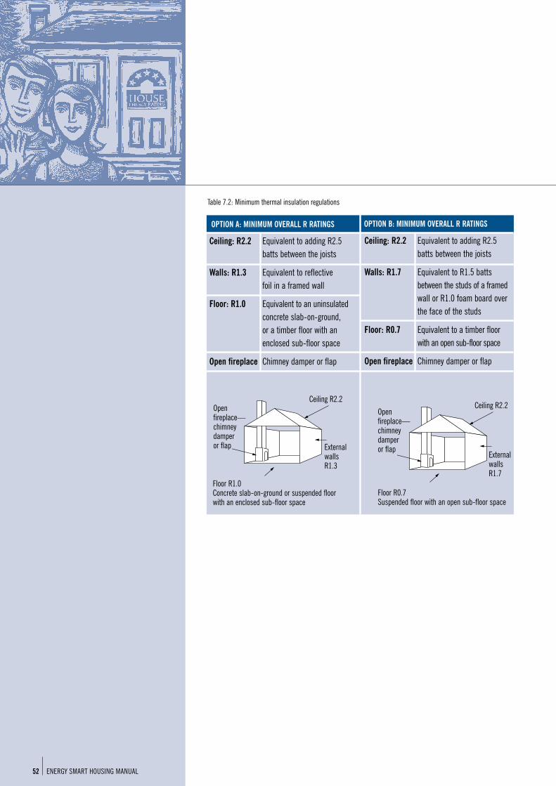
Table 7.2: Minimum thermal insulation regulations
ENERGY SMART HOUSING MANUAL52
Externalwalls R1.3
Openfireplace—chimney damper or flap
Floor R1.0 Concrete slab-on-ground or suspended floorwith an enclosed sub-floor space
Ceiling: R2.2 Equivalent to adding R2.5batts between the joists
Walls: R1.7 Equivalent to R1.5 battsbetween the studs of a framedwall or R1.0 foam board overthe face of the studs
Floor: R0.7 Equivalent to a timber floorwith an open sub-floor space
Open fireplace Chimney damper or flap
Ceiling R2.2
Externalwalls R1.7
Openfireplace—chimney damper or flap
Floor R0.7 Suspended floor with an open sub-floor space
OPTION A: MINIMUM OVERALL R RATINGS OPTION B: MINIMUM OVERALL R RATINGS
Ceiling: R2.2 Equivalent to adding R2.5batts between the joists
Walls: R1.3 Equivalent to reflective foil in a framed wall
Floor: R1.0 Equivalent to an uninsulatedconcrete slab-on-ground, or a timber floor with anenclosed sub-floor space
Open fireplace Chimney damper or flap
Ceiling R2.2

Common building materials, such as brick, timber or tiles have little inherent insulation value. The R values of some typical forms of wall construction are shown in Table 7.3. The regulationsrequire a minimum R value of 1.3 for walls. Only 200 mm aerated concrete meets the Victorianminimum insulation requirements by itself. Brick veneer and weatherboard walls have R values of 0.51 and 0.53 respectively, thus needing the addition of insulation to comply with the regulations.
Table 7.3: Estimated R values* of common wall construction types
WALL CONSTRUCTION OVERALL R VALUE
Weatherboard 0.55
Brick veneer 0.51
Cavity brick 0.53
Solid brick (230 mm thick) 0.44
Solid concrete (100 mm thick) 0.23
Solid concrete (200 mm thick) 0.30
Aerated concrete (100 mm block) 0.78
Aerated concrete (200 mm block) 1.54
Mud brick (300 mm block) 0.40
*As R value increases, the insulation benefit improves. Refer page7 for more information
ExemptionsCertain wall types have been exempted from the regulations. Cavity brick, mud brick, earth wall or other masonry walls thicker than 180 mm (excluding any cavity) are exempt from requiring wallinsulation, provided the floor is of concrete or masonry in direct contact with the ground. To ensureadequate levels of energy efficiency and comfort, however, it is recommended that such walls beinsulated to meet the minimum regulatory requirements.
Garages, where separated from the residential section of a house, are not subject to theregulations. Connecting walls between a garage and a house must still be insulated.
HIGHER INSULATION LEVELS RECOMMENDED The insulation levels prescribed by the Victorian regulations are minimum requirements only.Higher levels of insulation will increase energy savings and comfort levels. In Melbourne forinstance, adding R3.0 to ceilings and R1.5 to walls can save an additional 12% on energy billseach year. At a certain point, depending on the climate, the cost of adding extra insulation is notreflected in substantial savings on energy bills.
53© Sustainable Energy Authority Victoria 2002

ENERGY SMART HOUSING MANUAL54
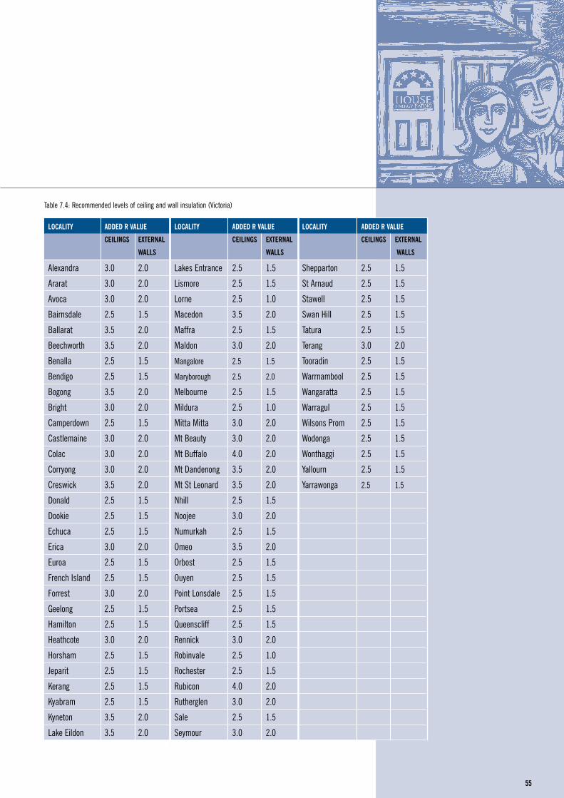
AS2627.1 (1993) contains recommended levels of insulation for locations throughout Australia.Table 7.4 is an extract of recommended levels of ceiling and wall insulation for Victoria. Note thatmany locations would benefit from installing more than the mandatory levels for greater energyefficiency and comfort, especially in areas which experience extreme temperatures.
Ceilings and wallsAdded R3.5–R4.0 in ceilings and added R2.0 insulation in walls should be installed if:
the home is in colder areas such as Ballarat, Macedon, Eildon or alpine areas.
higher levels of comfort and energy savings are desired.
Added R1.0 polystyrene boards should be installed to all solid masonry and cavity brick walls.Insulation should be placed on the outside of the inner wall leaf where there is a cavity.
FloorsThe minimum insulation regulations do not require floor insulation for concrete slab-on-groundconstruction. However energy savings will accrue from R1.0 polystyrene board slab-edgeinsulation, particularly if:
building in cold climate areas; or
slab heating is used.
Timber floors will benefit from additional insulation where:
there is no carpet over timber floors;
the underfloor space is open or well ventilated;
they overhang garages, balconies, etc.; or
you are building in cooler areas.
© Sustainable Energy Authority Victoria 2002 55
LOCALITY ADDED R VALUE LOCALITY ADDED R VALUE LOCALITY ADDED R VALUE
CEILINGS EXTERNAL CEILINGS EXTERNAL CEILINGS EXTERNAL
WALLS WALLS WALLS
Alexandra 3.0 2.0 Lakes Entrance 2.5 1.5 Shepparton 2.5 1.5
Ararat 3.0 2.0 Lismore 2.5 1.5 St Arnaud 2.5 1.5
Avoca 3.0 2.0 Lorne 2.5 1.0 Stawell 2.5 1.5
Bairnsdale 2.5 1.5 Macedon 3.5 2.0 Swan Hill 2.5 1.5
Ballarat 3.5 2.0 Maffra 2.5 1.5 Tatura 2.5 1.5
Beechworth 3.5 2.0 Maldon 3.0 2.0 Terang 3.0 2.0
Benalla 2.5 1.5 Mangalore 2.5 1.5 Tooradin 2.5 1.5
Bendigo 2.5 1.5 Maryborough 2.5 2.0 Warrnambool 2.5 1.5
Bogong 3.5 2.0 Melbourne 2.5 1.5 Wangaratta 2.5 1.5
Bright 3.0 2.0 Mildura 2.5 1.0 Warragul 2.5 1.5
Camperdown 2.5 1.5 Mitta Mitta 3.0 2.0 Wilsons Prom 2.5 1.5
Castlemaine 3.0 2.0 Mt Beauty 3.0 2.0 Wodonga 2.5 1.5
Colac 3.0 2.0 Mt Buffalo 4.0 2.0 Wonthaggi 2.5 1.5
Corryong 3.0 2.0 Mt Dandenong 3.5 2.0 Yallourn 2.5 1.5
Creswick 3.5 2.0 Mt St Leonard 3.5 2.0 Yarrawonga 2.5 1.5
Donald 2.5 1.5 Nhill 2.5 1.5
Dookie 2.5 1.5 Noojee 3.0 2.0
Echuca 2.5 1.5 Numurkah 2.5 1.5
Erica 3.0 2.0 Omeo 3.5 2.0
Euroa 2.5 1.5 Orbost 2.5 1.5
French Island 2.5 1.5 Ouyen 2.5 1.5
Forrest 3.0 2.0 Point Lonsdale 2.5 1.5
Geelong 2.5 1.5 Portsea 2.5 1.5
Hamilton 2.5 1.5 Queenscliff 2.5 1.5
Heathcote 3.0 2.0 Rennick 3.0 2.0
Horsham 2.5 1.5 Robinvale 2.5 1.0
Jeparit 2.5 1.5 Rochester 2.5 1.5
Kerang 2.5 1.5 Rubicon 4.0 2.0
Kyabram 2.5 1.5 Rutherglen 3.0 2.0
Kyneton 3.5 2.0 Sale 2.5 1.5
Lake Eildon 3.5 2.0 Seymour 3.0 2.0
Table 7.4: Recommended levels of ceiling and wall insulation (Victoria)

Insulation selectionWhen selecting insulation, ensure that the material is:
the recommended R value for the relevant area;
appropriate for the intended installation;
a material covered by Australian Standards or approved by other recognised testingauthorities; and
sufficient to meet local building authority requirements.
A list of recommended levels of ceiling and wall insulation is provided in table 7.4.
Fire safetyAll insulation products should be independently tested for flammability prior to being sold.AS1530.1 (1989) provides a standard testing procedure to measure:
ignitability;
the spread of flame;
if the material is heat evolved; and
if the material is smoke evolved.Ignitability is rated on a scale of zero to 20, while other factors are rated on a scale of zero to ten.The lower the number, the smaller the risk.
Cellulose fibre must be treated with a fire retardant such as a mix of borax and boracic acidduring manufacture. The treatment ensures that, if the material does ignite, the flame will notspread. Expanded and extruded polystyrene are combustible, and should only be installed betweenfire-resistant surfaces (this includes plasterboard). Natural wool is flame resistant, provided onlypure, new scoured wool is used. Wool which is oily, or has synthetic fibres mixed with it ispotentially flammable.
As there is no Australian Standard, the quality of individual products may vary considerably.Ensure that the manufacturer supplies details of independent fire resistance tests. All otherinsulation products are essentially non-combustible.
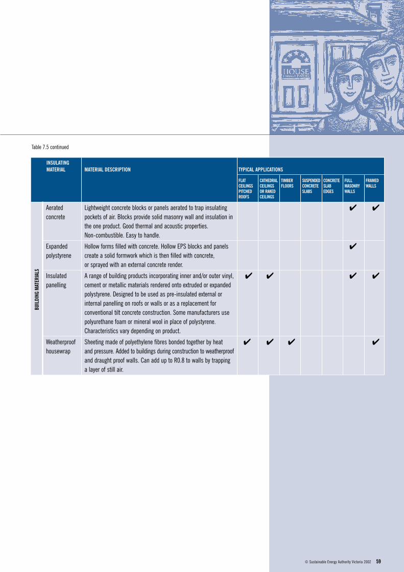
Suggested applications for insulation productsTable 7.5 provides general information about the various insulation products currently available,together with the most common applications for each product. It is possible to adapt mostproducts for different uses if required.
ENERGY SMART HOUSING MANUAL56

BATT
SAN
DBL
ANKE
TSBO
ARDS
INSULATING MATERIAL MATERIAL DESCRIPTION TYPICAL APPLICATIONS
FLAT CATHEDRAL TIMBER SUSPENDED CONCRETE FULL FRAMEDCEILINGS CEILINGS FLOORS CONCRETE SLAB MASONRY WALLSPITCHED OR RAKED SLABS EDGES WALLSROOFS CEILINGS
Glasswool Manufactured from melted glass spun into a mat of fine fibre. ✔ ✔ ✔ ✔Made to an Australian Standard and commonly sold in DIY packs with R values clearly labelled. Easy to cut and install. Remains inert. Should not be compressed or moistened. Butt all ends and edges together firmly.
Rockwool Volcanic rock melted at high temperatures and spun into a mat of ✔ ✔ ✔ ✔fine fibres. Denser than glasswool so R value per unit thickness is higher. Good sound absorption properties. See glasswool for other characteristics.
Glasswool/ Characteristics same as above with foil providing increased ✔ ✔rockwool— insulating value (in summer) and moisture resistance. R value foil attached depends on method of installation.
Natural wool Should only be made from new, scoured wool. Must be treated with ✔ ✔ ✔ ✔a vermin/rot proofing agent during the scouring process. Dirt or grease can add to flammability. Some include synthetic (usually polyester) fibres to reduce settling and compression. The Wool Mark logo signifies the batt is made from pure wool only. No Australian Standard as yet.
Polyester Manufactured from polyester strands spun into a mat. Similar physical ✔ ✔ ✔ ✔properties to glasswool and rockwool. Non-toxic, with no known physical or health hazards. Does not burn, but will melt if exposed to a direct flame. Butt all edges firmly. No Australian Standard as yet.
Extruded Rigid boards of close cell polystyrene which retain air but exclude ✔ ✔ ✔ ✔ ✔ ✔polystyrene water. High R value per unit thickness. Suitable where space is limited. (styrofoam) Easy to cut and install. Should only be used between non-combustible
materials such as brick, aluminium and plasterboard. Can be rendered. Most commonly used material for slab-edge and cavity brick wall insulation. Greater structural strength and moisture resistance than expanded polystyrene.
Expanded Semi-rigid boards of white polystyrene beads. High water absorbency. ✔ ✔ ✔ ✔ ✔ ✔polystyrene Combustible and should only be used between fire resistant materials. (EPS) Easy to cut and install. Available as preclad panels.
Expanded Expanded polystyrene boards sandwiched between reflective foil. ✔ ✔polystyrene Characteristics same as above, however, higher R values achieved —foil attached due to the addition of two reflective surfaces and higher water
resistance.
57© Sustainable Energy Authority Victoria 2002
Table 7.5: Insulation products and possible applications

ENERGY SMART HOUSING MANUAL58
REFL
ECTI
VERE
FLEC
TIVE
INSULATING MATERIAL MATERIAL DESCRIPTION TYPICAL APPLICATIONS
FLAT CATHEDRAL TIMBER SUSPENDED CONCRETE FULL FRAMEDCEILINGS CEILINGS FLOORS CONCRETE SLAB MASONRY WALLSPITCHED OR RAKED SLABS EDGES WALLSROOFS CEILINGS
Cellulose fibre Manufactured from waste paper pulverised into a fine fluff. ✔ ✔Fire retardant added. Generally pumped into roof by contractor. Difficult for the purchaser to ensure uniform thickness and density if installing by hand. Product should be manufactured to AS2462 and installed in a consistent, even layer. Must be kept dry. Must not be compressed. Settling of up to 20 mm per 100 mm thickness may occur, decreasing performance.
Granulated Properties as per rockwool batts. However, material is loose, not a ✔ ✔ ✔ ✔rockwool prefabricated mass. Treated with a water repellent. Should be
installed in an even, consistent manner.
Natural wool Made from off-cuts of natural sheep’s wool. Quality and density can ✔ ✔vary considerably, affecting the R value. Other characteristics sameas for natural wool batts.
Reflective foil Aluminium foil laminated with glass fibre reinforcement. Supplied in ✔ ✔ ✔ ✔rolls, one side often painted with an anti-glare paint. Does not have a significant R value itself, and requires a sealed air space of at least 25 mm between foil and solid surface to achieve full insulationqualities. Gaps in foil reduce performance. Valuable in combination with bulk insulation for enhancing performance. Useful barrier against transfer of moisture. Reflective surface needs to remain clean and dust-free. Dust build-up reduces R value.
Concertina Expandable concertina folded foil-paper laminate. Can be adjusted ✔ ✔foil batts to suit varying gaps. Other characteristics identical to laminate
bought as rolls.
Multi-cell Prefabricated batts made from layers of laminated foil with partition ✔ ✔ ✔foil batts reflective strips to produce a cell construction with enclosed air
cavities. Gaps will significantly reduce performance. Double or triple-cell batts (two and three layers of cells, respectively) may be necessary to achieve adequate winter insulation levels. Dust build-up reduces R value.
LOOS
EFI
LL
Table 7.5 continued
BUIL
DING
MAT
ERIA
LS
59© Sustainable Energy Authority Victoria 2002
INSULATING MATERIAL MATERIAL DESCRIPTION TYPICAL APPLICATIONS
FLAT CATHEDRAL TIMBER SUSPENDED CONCRETE FULL FRAMEDCEILINGS CEILINGS FLOORS CONCRETE SLAB MASONRY WALLSPITCHED OR RAKED SLABS EDGES WALLSROOFS CEILINGS
Aerated Lightweight concrete blocks or panels aerated to trap insulating ✔ ✔concrete pockets of air. Blocks provide solid masonry wall and insulation in
the one product. Good thermal and acoustic properties. Non-combustible. Easy to handle.
Expanded Hollow forms filled with concrete. Hollow EPS blocks and panels ✔polystyrene create a solid formwork which is then filled with concrete,
or sprayed with an external concrete render.
Insulated A range of building products incorporating inner and/or outer vinyl, ✔ ✔ ✔ ✔panelling cement or metallic materials rendered onto extruded or expanded
polystyrene. Designed to be used as pre-insulated external or internal panelling on roofs or walls or as a replacement for conventional tilt concrete construction. Some manufacturers use polyurethane foam or mineral wool in place of polystyrene. Characteristics vary depending on product.
Weatherproof Sheeting made of polyethylene fibres bonded together by heat ✔ ✔ ✔ ✔housewrap and pressure. Added to buildings during construction to weatherproof
and draught proof walls. Can add up to R0.8 to walls by trapping a layer of still air.
Table 7.5 continued

Installing insulationINSTALLATION GUIDELINESIt is vital that insulation is installed with careful attention to detail, as incorrect or inappropriateinstallation will significantly decrease performance. For instance, failure to butt all ends and edgesof batts to give a snug fit could result in 5% of the ceiling area not being covered, losing up to50% of the potential insulation benefits.
RELEVANT STANDARDS FOR INSTALLATION Various Australian Standards and national codes of practice cover the installation of insulationproducts with key standards set out below.
Bulk insulation must be installed in compliance with AS3999: Thermal insulation of dwellings—Bulk insulation—Installation requirements.
Reflective foil insulation must be installed in compliance with AS1904: Code of practice forinstallation of reflective foil laminate in buildings.
All electrical wiring encased in insulation must conform to AS3000: Electrical installations—buildings, structures and premises. In existing dwellings, which may not conform to this standard,spacers must be installed to ensure that wiring is not in contact with the insulation (refer AS3999).
It is best to keep wiring clear of insulation, e.g. run wiring on top of ceiling joists.
Installation safety when installing mineral wool (glasswool and rockwool), insulation should comply with Work Safe Australia’s National code of practice for safe use of synthetic mineralfibres (1990).
PRINCIPLES OF INSTALLATIONThe following installation principles will ensure the best possible performance from insulation.
Avoid gaps in insulation
Do not compress bulk insulation
Eliminate thermal bridges
Allow clearance around appliances and fittings
Protect insulation from contact with moisture
Provide a sealed air space with reflective insulation
Provide vapour and moisture barriers to prevent condensation
Eliminate thermal bridges
ENERGY SMART HOUSING MANUAL60

SITUATION TECHNIQUE
Gaps where insulation not installed Fit batts snugly leaving no gaps around ducts and pipes
Gaps between pieces of insulation Make sure corners, junctions of wall, floor and ceiling are fully covered
Compression of bulk insulation Retain maximum thickness, allow to fully expand
Structural framing—metal, timber Isolate metal framing from contact with cladding, or increase level of added insulation. Isolate timber framing from contact with cladding in alpine areas
Metal window frames Insulate window frames or install windows with thermal breaks
CLEARANCE AROUND APPLIANCES AND FITTINGS Some appliances and fittings, such as recessed downlights and heater flues, require free spacearound them for the dissipation of heat, to reduce fire hazard. Insulation should not be placedagainst these fixtures. Regulations and manufacturers’ recommendations should always bechecked before installing insulation. Table 7.7 sets out some common installation clearances.
Table 7.7: Insulation clearance requirements
ITEM TO BE CLEARED TECHNIQUE
Recessed downlights Minimum clearance of 25 mm
Flues and exhaust fans Minimum clearance of 90 mm
Loose fill insulation material Use barriers to restrain and ensure adequate clearance
Electrical wiring (existing home) Check by electrician before installing insulation. Keep wiring clear of insulation. Restrain loose fill material by spacers
61© Sustainable Energy Authority Victoria 2002
insulation
flue
90 mm gap
Figure 7.10: Insulation clearance around flues
suitablerestraint
insulation
exhaust fan
90 mm
Figure 7.11: Insulation clearance around exhaust fans
suitablerestraint
insulationrecessed downlight
25 mm
ceiling lining
Figure 7.12: Insulation clearance around recesseddownlights
Table 7.6: Some installation techniques to improve thermal performance
CondensationAir always contains a certain amount of water vapour. This vapour can originate from manysources around the home—respiration, cooking, bathrooms and laundries, indoor plants, LPG gasheaters and so on. When moist air is cooled below its dewpoint (i.e. cooled to a temperature atwhich it cannot contain all the water originally present), and if the cooling is caused by contactwith a colder surface, the vapour changes to liquid droplets on that surface. This phenomenon iscalled condensation.
Condensation is more likely to occur:
where there is a low ventilation rate within the walls or roof space, insufficient to removewater vapour (e.g. cathedral and flat roof ceilings);
where daytime temperatures do not exceed 5°C (e.g. in alpine areas in winter); and
where high amounts of water vapour are generated internally but not mechanically exhausted.
CONDENSATION ON INTERIOR SURFACESInsulation, correctly installed, can keep the interior surface temperature of ceilings and externalwalls above the dewpoint, preventing condensation on these surfaces. Condensation controlinvolves preventing moist air from coming into contact with cold surfaces below the dewpoint of the air by one or more of the following means:
removing moisture-laden air by controllable ventilation or exhaust fans;
insulating to keep ceiling and wall temperatures above dewpoint, and to reduce the differencebetween room temperature and surface temperatures; and
background heating to prevent interior surfaces from cooling below the dewpoint.
INTERSTITIAL CONDENSATIONIn cold conditions, condensation may occur within the roof space (especially where metal deckroofs are used) or walls and within the insulation itself. Exhausting moist air into the roof space or wall cavity may also cause condensation. Such condensation is known as interstitialcondensation. It can cause mould, mildew and rotting of building components. In addition, the effectiveness of insulation is significantly reduced when it contains water.
Condensation is a particular hazard in cathedral and flat roof systems where the low ventilationrate within the roof space may be insufficient to remove water vapour contained in the air, or condensed upon or within building components.
These problems can be avoided by either providing sufficient ventilation within the wall or roofspace to remove water vapour, or by installing vapour barriers such as reflective foil on the warmside of insulation. This prevents water vapour from contacting cool surfaces within the walls orroof structure.
Exhaust fans in buildings with metal deck or tiled roofs with sarking (reflective foil installed underroofing material for weatherproofing) must be ducted to the atmosphere.
ENERGY SMART HOUSING MANUAL62

PROTECT INSULATION FROM CONTACT WITH MOISTURE Masonry walls are not waterproof. In both brick veneer and double-brick wall construction a cavitybetween the external masonry wall and the internal lining keeps the internal lining dry. Moisture onthe internal face of the external masonry wall can drain away through weepholes or evaporate intothe cavity. Table 7.8 sets out techniques to prevent the insulation from absorbing moisture fromthe external leaf and losing effectiveness.
Table 7.8: Keeping insulation dry in wall cavities
SITUATION TECHNIQUE
Brick veneer construction Restrain bulk insulation within the frame. Reflective foil laminate, polypropylene lashing, nylon cord, galvanised wire or building paper can be used to keep bulk insulation in place
Cavity masonry walls Restrain bulk insulation to maintain at least 30 mm cavity
Existing wall cavities Use ‘cavity fill’ water-repellent loose-fill granularrockwool insulation. Contains water-repelling agent to prevent absorption of moisture. Not allowed by some building authorities because of concern over moisture penetration
PROVIDE A SEALED AIR SPACE WITH REFLECTIVE INSULATION Reflective insulation adjacent to a solid surface without an airspace, has no insulative value andacts only as a vapour barrier. To add thermal resistance, reflective insulation must face a sealedair space (see figure 7.13).
To maximise the effectiveness of reflective foil:
maintain a sealed air space of at least 25 mm;
eliminate air movement between air spaces on either side of the foil;
overlap sheets by 150 mm and tape over joins;
seal any gaps;
use face-of-wall brick ties instead of ties which penetrate the foil; and
reflective surfaces should be kept clean and dust free, vertical installation is best for this.
63© Sustainable Energy Authority Victoria 2002
punctured foilor building paper,or housewrap
R1.5 bulkinsulation
externalweatherboards
Figure 7.13: Reflective insulation with sealed airspace (weatherboard wall)

PROVIDE BARRIERS TO PREVENT CONDENSATIONCondensation in bulk insulation reduces its insulating properties significantly. Vapour barriers stopthe transmission of water vapour generated inside the home, through the building elements andinto the building structure.
A vapour barrier installed on the warm side of insulation will prevent moist air from contacting a cold surface (see figure 7.14). The vapour barrier should be continuous, with no breaks. Vapour barriers include well-maintained painted surfaces, polythene sheeting and aluminium foil.If aluminium foil is required to act as both thermal insulation and a vapour barrier, ensure that astill airspace is provided.
Painted surfaces generally provide adequate protection from condensation in Victorian climates.
Moisture barriers stop the transmission of water from outside the home entering through thebuilding elements. Sarking may be installed directly under roofing material to act primarily as amoisture barrier. It is usually made of reflective foil laminate (which adds to the insulation effect),or other waterproof material.
HEALTH AND SAFETYGlasswool, rockwool and cellulose fibreClaims have been made regarding exposure to glasswool and rockwool as an apparent ongoinghealth risk, particularly in reference to cancer. However, continuing medical research has failed tofind any evidence to support these claims. In 1994, The Institute of Respiratory Medicine RoyalPrince Alfred Hospital, NSW, investigated the Respiratory Health of Australian Glasswool andRockwool Manufacturing Industry, for the Insulation Wools Research Advisory Board. They foundno evidence of occupational asthma, pulmonary fibrosis or lung cancer.
The main risk associated with glasswool and rockwool is short-term irritation to skin, eyes, noseand throat. This reaction is a physical reaction, not an allergic reaction. Cellulose fibre may causeminor eye and respiratory irritation when handled. For most people, the irritation quicklydisappears. Once installed, the insulation should present no further problems. However additionalweatherstripping should be installed around access holes and ceiling cracks.
The irritation caused by these fibres can generally be avoided by:
minimising dust release when opening insulation wrapping;
wearing long-sleeved, loose-fitting clothing and gloves during installation;
wearing goggles and head covering, especially when installing insulation overhead;
wearing a half-face (Class L or M) disposable respirator during work in enclosed or poorly-ventilated spaces;
washing skin with warm, soapy water following installation; and
washing protective clothing separately.
Reflective foilReflective foil can cause dangerous glare and even sunburn if installed outdoors. Anti-glareproducts should be selected if installed in sunlight and adequate eye protection should be worn.
ENERGY SMART HOUSING MANUAL64
outside warm side
stud
plasterboard lining
foil or painted plasterboard as a vapour barrier
cavity
bulk insulation
Figure 7.14: Place vapour barrier on the warm side ofinsulation (brick veneer wall)

© Sustainable Energy Authority Victoria 2002
Installation optionsCEILING INSTALLATIONThe following details illustrate ways of achieving an overall minimum insulation level of at leastR2.2 for a variety of ceiling and roof types for Victoria.
FLAT CEILINGS WITH PITCHED ROOFSThis is the most common form of ceiling and the easiest to insulate.
Bulk insulation between ceiling joistsThe use of only bulk insulation between joists is shown in figure 7.15. With added R2.5 bulkinsulation, the overall R value is 2.2. This can be increased to 2.7 by using R3.0 or higher.
Bulk insulation and reflective foil between ceiling joistsThe use of bulk insulation between ceiling joists as well as reflective foil directly under the roof isshown in figure 7.16. The use of double-sided reflective foil placed directly under the roofimproves summer and winter performance and provides a moisture barrier (sarking). Foil alonehas an overall R value of approximately 0.5 and must be supplemented by other insulation tosatisfy the minimum insulation level. With added R2.0 bulk insulation, the overall value is R2.3.This can be increased to R2.7 by using R2.5 or greater.
Ceilings with exposed raftersThese roofs include sloping ceilings, cathedral ceilings, vaulted ceilings, flat and skillion roofs.Ceilings with exposed rafters require insulation to be installed during construction, as it cannot be accessed later. Roof space can be very limited in these situations. Note that 100–125 mm batten height isneeded to avoid compression of R2.5 bulk insulation. For this reason consider materials that offer the same R value with less thickness, e.g. extruded or expanded polystyrene boards.
These roofs are more susceptible to problems of condensation due to the low ventilation rate in the roof space, so a vapour barrier installed directly above the ceiling lining may be a useful inclusion.
Bulk insulation and vapour barrier between battens A metal deck roof with bulk insulation between battens with a vapour barrier is shown in figure7.17. With added R2.5 bulk insulation, the overall value is R2.2. The overall R value can beincreased to 2.7 by using R3.0 bulk insulation. An alternative solution is to use 50 mm extrudedpolystyrene boards laid above the ceiling lining requiring no vapour barrier and providing anoverall R value of 2.3.
Bulk insulation blanket over battensA metal deck roof with bulk and reflective insulation is shown in figure 7.18. With added R2.5 foilbacked batts or blankets, the overall R value is 2.2. Compression of bulk insulation reduces itseffectiveness. An alternative solution is to use 25 mm expanded polystyrene foil boards installedbetween the ceiling and metal deck roof, with a 25 mm air space above and below. This wouldprovide an approximate overall R value of 2.2.
65
ceiling joist
R2.5 bulkinsulation
ceiling batten
ceiling joist
R2.0 bulkinsulation
ceiling batten
double-sided reflectivefoil laminate
Figure 7.16: Bulk insulation between ceiling joists and reflective foil under roof (overall R value 2.3)
rafter
roofing batten
vapour barrier(if necessary) ceiling lining
R2.0 bulk insulation
double-sided reflective foillaminate (sarking)
roofing
Figure 7.17: Bulk insulation between battens andvapour barrier under metal roof (overall R value 2.2)
roofing
reflective foilfacing down
exposed rafter
110 mm orhigher batten
ceilinglining
R2.5 foil-backed blanket
insulationcompressed
Figure 7.18: Foil backed bulk insulation over battensunder metal roof (overall R value at least 2.2)
Figure 7.15: Bulk insulation between joists (overall Rvalue 2.2)

Bulk insulation and reflective foil between counter battens under tiled roofA tiled roof with bulk and reflective insulation is shown in figure 7.19. With added R2.5 bulkinsulation and reflective foil, the overall R value is at least 2.2. This can be increased to 2.7 byusing R3.0 batts, requiring a minimum batten depth of 125 mm.
Ceilings with concealed raftersSuch roofs include sloping ceilings, cathedral ceilings, vaulted ceilings, flat and skillion roofs. Bulk insulation may be placed between rafters, and moisture problems avoided by placing avapour barrier directly above the ceiling lining. Extruded polystyrene products do not require a vapour barrier.
Bulk insulation between rafters and vapour barrier A metal deck roof with air space, bulk insulation and a vapour barrier beneath is shown in figure 7.20. With added R2.5 bulk insulation, the overall R value is 2.2. This can be increased to 2.7 by using R3.0 or higher batts, requiring a minimum rafter depth of 125 mm.
Bulk insulation between rafters and vapour barrier A tiled roof with bulk insulation and a vapour barrier beneath is shown in figure 7.21. Note thatsarking is used below the tiles as a moisture barrier. With added R2.5 bulk insulation, the overallR value is at least 2.2. This can be increased to 2.7 by using R3.0 or higher batts, requiring aminimum rafter depth of 125 mm.
EXTERNAL WALL INSTALLATION The following notes provide information on correctly installing wall insulation and illustrate ways of achieving at least an overall minimum insulation level of R1.3 for a variety of external wallconstruction types (refer to page 52 for minimum insulation level for Victoria).
Existing wallsFor existing housing, wall insulation can be installed by removing internal or external linings toaccess the cavity, and then replacing the linings. Alternatively wall cavities can be filled withgranulated rockwool, if permitted by local building regulations. It is costly to insulate existing wallsand often difficult to access the cavity. In these circumstances the insulation installation cost maybe better invested in extra ceiling or floor insulation, or other energy saving measures.
ENERGY SMART HOUSING MANUAL66
tile batten
ceiling lining
100 mm or highercounter batten
exposed rafter
R2.0 bulk insulation
vapour barrier(if necessary)
double-sided reflective foillaminate (sarking)
Figure 7.19: Bulk insulation and reflective foil betweencounter battens under tiled roof (overall R value atleast 2.2)
rafter
roofing batten
vapour barrier(if necessary) ceiling lining
R2.0 bulk insulation
double-sided reflective foillaminate (sarking)
roofing
Figure 7.20: Bulk insulation between rafters andvapour barrier under metal roof (overall R value 2.2)
tile batten
double-sided reflectivefoil laminate(sarking)
rafter
R2.0 bulkinsulation
vapour barrier(if necessary)
tiles
Figure 7.21: Bulk insulation between rafters andvapour barrier under tiled roof (overall R value 2.2)

Wall sections with a roof spaceIt is essential to insulate vertical wall sections within the roof space above ceilings of differentheights, as these can be a major source of heat loss. These sections should be insulated to thesame level as the ceiling (see figure 7.22).
Vapour barriersWhere there is a risk of condensation, install reflective foil or polythene sheets on the warm sideof wall insulation to act as a vapour barrier. Well-maintained painted or foil-backed plasterboardalso act as vapour barriers (see figure 7.15).
Framed walls: Brick veneer and weatherboardReflective foil should be installed on the outside of wall studs, creating a still air layer on eitherside of the foil. The material must be continuous, and any holes, tears or joins in the foil must betaped over.
For weatherboard or cladding construction (where the outer skin is in contact with the timberframing), the foil should be dished between the studs to create still air pockets on both sides.Perforated or ‘breather’ foil should be used with weatherboard walls, as it allows the timber tobreathe and prevents warping.
Framed walls with reflective foil laminateBy installing double-sided reflective foil on the outside of the framed walls (studs), achieves anoverall R value of 1.3. This can be increased to R1.8 if combined with concertina-style reflectivefoil stapled between the studs as well (leaving at least 25 mm air space between them). The use of reflective foil over framing is shown in figure 7.23. Suitable materials are double-sidedreflective foil laminate and reflective building paper.
Framed walls with reflective foil battsThe use of reflective foil batts between framing is shown in figure 7.24. Suitable materials areconcertina-style reflective foil laminate or single-cell foil batts, both stapled between the studs.
The overall R value is 1.4, and can be increased to 1.8 by using two layers of concertina battsstapled between the studs (leaving at least 25 mm air space between them), or by using double-cell foil batts stapled between the studs.
Weatherboard walls with bulk insulation and reflective foilThe use of weatherboard walls with bulk insulation is shown in figure 7.25. Weatherboards shouldbe lined with a fire retardant building paper or perforated reflective foil attached to the outside ofthe frame, with R1.5 bulk insulation between the studs. The overall R value is at least 1.7 and canbe increased to at least 2.2 by using batts with an R value of 2.0.
67© Sustainable Energy Authority Victoria 2002
up to R3.5ceiling insulation
insulate walls between ceilings to the same rating as the ceilingspay special
attention to cathedraltype ceilings
up to R2.0 wall insulation insulate concrete
slab edgesinsulate cavitybrick walls
double-sidedreflective foilinternal
wall lining
stud
minimumoverlap150 mm
tape over joins
Figure 7.25: Weatherboard walls with bulk insulationand reflective foil (overall R value at least 1.7)
punctured foilor building paper,or housewrap
R1.5 bulkinsulation
externalweatherboards
concertina-style foil
nogging
stud
internal wall lining
Figure 7.24: Framed walls with reflective foil batts(overall R value 1.4)
Figure 7.23: Framed walls with reflective foil (overallR value 1.3)
Figure 7.22: Insulate vertical wall sections betweenceilings of different heights

Brick veneer walls with bulk insulation between studsThe use of bulk insulation between studs is shown in figure 7.26. Strapping, reflective foil orbuilding paper should be used to prevent R1.5 batts falling against the cladding or bricks andabsorbing moisture from them. The overall R value is 1.7 and can be increased to 2.2 by usingbatts with an R value of 2.0.
Brick veneer walls with insulation boards across studsThe use of bulk insulation across the outside face of studs is shown in figure 7.27. Insulatingacross the outside of the frame reduces thermal bridging through the frame and achieves a betteroverall insulation value when comparing the addition of products with equivalent R values. This method is particularly suitable for metal framing. Although other products can be used, ten millimetres of foil-faced expanded polystyrene or R1.0 extruded polystyrene boards are themost practical for this type of insulation, as they maintain a 25 mm cavity between the externalcladding and the insulation. The overall R value is 1.7 and can be increased to over 2.0 by using thicker boards.
Double brick cavity wallsInsulating a double brick wall is relatively simple if insulation is installed during it’s construction. For established homes, existing walls can be insulated using either loose-fill cavity insulation or internal or external insulation, however it is difficult and more costly to install. Internalinsulation is less effective than external insulation as it isolates the thermal mass benefits of the wall from the inside of the dwelling and reduces the internal size of the room.
New cavity brick wall with insulation boards within the cavityThe use of insulation boards in the cavity of new walls is shown in figure 7.28. The boards are pushed over the brick ties of the internal brick wall. Foil-faced expanded polystyrene (ten millimetres) or R 1.0 extruded polystyrene boards are typically used. They are self-supportingand need only small clips to keep them in place. The overall R value is at least 1.7.
Existing cavity brick wall with cavity fill insulationThe use of cavity fill insulation in an existing wall is shown in figure 7.29. Subject to local buildingregulations, the cavity can be filled with water-repellent loose-fill rockwool insulation. R 1.0 hydrophobic loose-fill rockwool is also suitable. The overall R value is 1.5.
ENERGY SMART HOUSING MANUAL68
internalwalllining
R1.5 batt
nogging
stud
brickveneer
strapping, e.g. nylon string or galvanised wire
Figure 7.26: Framed walls with bulk insulationbetween studs (overall R value 1.7)
R1.0 polystyrene board stud
nogging
R1.0 extruded polystyrene inner leaf
of brickwork
wall tie clip
20 mm air space
outer leaf of brickwork
Figure 7.28: New cavity brick wall with bulk insulationwithin the cavity (overall R value 1.7)
water repellent loosefill wall insulation
internal plasterboard lining
Figure 7.29: Existing cavity brick wall with cavity fillinsulation (overall R value 1.5)
Figure 7.27: Brick veneer walls with bulk insulationacross the studs (overall R value 1.7). Particularlysuitable where metal framing is used
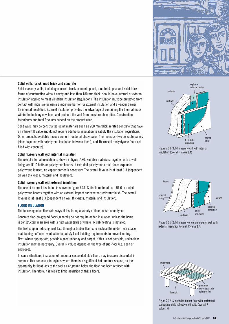
Solid walls: brick, mud brick and concreteSolid masonry walls, including concrete block, concrete panel, mud brick, pise and solid brick forms of construction without cavity and less than 180 mm thick, should have internal or externalinsulation applied to meet Victorian Insulation Regulations. The insulation must be protected fromcontact with moisture by using a moisture barrier for external insulation and a vapour barrier for internal insulation. External insulation provides the advantage of containing the thermal masswithin the building envelope, and protects the wall from moisture absorption. Constructiontechniques and total R values depend on the product used.
Solid walls may be constructed using materials such as 200 mm thick aerated concrete that havean inherent R value and do not require additional insulation to satisfy the insulation regulations.Other products available include cement-rendered straw bales, Thermomass (two concrete panelsjoined together with polystyrene insulation between them), and Thermocell (polystyrene foam cellfilled with concrete).
Solid masonry wall with internal insulationThe use of internal insulation is shown in figure 7.30. Suitable materials, together with a walllining, are R1.0 batts or polystyrene boards. If extruded polystyrene or foil-faced expandedpolystyrene is used, no vapour barrier is necessary. The overall R value is at least 1.3 (dependenton wall thickness, material and insulation).
Solid masonry wall with external insulationThe use of external insulation is shown in figure 7.31. Suitable materials are R1.0 extrudedpolystyrene boards together with an external impact and weather resistant finish. The overall R value is at least 1.3 (dependent on wall thickness, material and insulation).
FLOOR INSULATIONThe following notes illustrate ways of insulating a variety of floor construction types.
Concrete slab-on-ground floors generally do not require added insulation, unless the home is constructed in an area with a high water table or where in-slab heating is installed.
The first step in reducing heat loss through a timber floor is to enclose the under-floor space,maintaining sufficient ventilation to satisfy local building requirements to prevent rotting. Next, where appropriate, provide a good underlay and carpet. If this is not possible, under-floorinsulation may be necessary. Overall R values depend on the type of sub-floor (i.e. open orenclosed).
In some situations, insulation of timber or suspended slab floors may increase discomfort insummer. This can occur in regions where there is a significant hot summer season, as theopportunity for heat loss to the cool air or ground below the floor has been reduced withinsulation. Therefore, it is wise to limit insulation of these floors.
69© Sustainable Energy Authority Victoria 2002
outside
solid wall
polythene moisture barrier
internalliningR1.0 bulk
insulation
Figure 7.30: Solid masonry wall with internalinsulation (overall R value 1.4)
inside
internallining
solid wall
R1.0insulation
externalrendering
outside
Figure 7.31: Solid masonry or concrete panel wall withexternal insulation (overall R value 1.4)
timber floor
floor joist
puncturedconcertina-stylereflective foil
Figure 7.32: Suspended timber floor with perforatedconcertina-style reflective foil batts (overall R value 1.0)

Suspended floorsSuspended timber floor with reflective foil The use of perforated concertina-style reflective foil batts with a suspended timber floor is shownin figure 7.32. Perforated foil maintains a still layer of air under the floorboards, whilst allowingmoisture to escape, preventing warping and deterioration of the flooring. The foil can be stapledbetween the floor joists (where concertina-style foil is used), or reflective foil laminate placed over the joists and dished between them, to provide a still air space, before the flooring is laid.The overall R value is at least 1.0.
Suspended timber floor with bulk insulation between joistsThe use of bulk insulation between the joists of a suspended timber floor is shown in figure 7.33.Supporting mesh (non-degradable material, e.g. nylon, galvanised wire) should be laid under thefloor joists. Suitable materials for insulation are R1.0 batts or polystyrene boards. Boards can beattached to the underside of the joists using fixing spikes or long staples. The overall R value is atleast 1.3.
Suspended concrete slab with polystyrene board insulationThe use of polystyrene boards below a suspended concrete slab is shown in figure 7.34. R1.0 expanded or extruded polystyrene boards are attached to the underside of the slab usingretaining pins. Insulation is essential for heated suspended slabs. The overall R value is 1.2.
Slab-on-ground floorsEdge insulation is recommended for a heated slab, or a slab-on-ground where the water table ishigh, as approximately 80% of heat loss from the slab occurs through the edge. For structuralreasons it is not recommended that insulation be installed under concrete edge beams.
Heated concrete slab with edge insulationThe use of edge insulation with a heated slab-on-ground floor is shown in figure 7.35. Insulationshould be installed before the concrete is poured. Ensure that insulation forms a continuousbarrier around the slab edge, with no gaps. In termite-prone areas, the slab edge needs to bevisible for inspections. Contact manufacturers for specific installation details, especially withregard to placement of insulation in relation to the waterproof membrane. The only suitablematerials, due to their waterproof qualities, are extruded and expanded polystyrene boards of R1.0 or higher. The overall R value is 2.2 in the insulated section only.
ENERGY SMART HOUSING MANUAL70
timber floor
R1.0 bulkinsulation supporting
mesh
Figure 7.33: Suspended timber floor with bulkinsulation between the joists and supporting mesh(overall R value at least 1.3)
R1.0polystyrene board
tapesuspended slab
retaining pinwith expandingplug end
Figure 7.34: Suspended concrete slab with polystyreneboard insulation (overall R value 1.2)
Figure 7.35: Heated concrete slab, insulated aroundthe edge with extruded polystyrene (overall R value 2.2).
R1.0 polystyreneedge insulation
waterproofmembrane
slab
ground level