energy sb-sd-scw600 compact controller with hot water ... · energy sb-sd-scw600 compact controller...
TRANSCRIPT

Energy SB-SD-SCW600 Compact controller with Hot Water management for domestic heat pumps
<IMG INFO> 425,15 349,55 0 2 46,85 14,15 -1
EN
CONTENTS 1 How to use this manual........................................................................................................................................ 7 2 Introduction ............................................................................................................................................................. 8
2.1 General Description......................................................................................................................................................................... 8 2.1.1 Typical applications: .......................................................................................................................................................................................................................... 8 2.1.2 Technical data: .................................................................................................................................................................................................................................... 8 2.1.3 Main functions: ................................................................................................................................................................................................................................... 8
2.2 Models and Features ....................................................................................................................................................................... 8 3 User Interface (folder PAr/UI) ............................................................................................................................ 9
3.1 Keys...................................................................................................................................................................................................... 9 3.1.1 Description of keys and associated functions............................................................................................................................................................................ 9 3.1.2 Stand-by.............................................................................................................................................................................................................................................. 11
3.1.2.1 Device ‘On’ --> ‘Standby’.................................................................................................................................................................................................... 11 3.1.2.2 Device ‘Standby’ --> ‘On’.................................................................................................................................................................................................... 11
3.1.3 Description of keys - combined action...................................................................................................................................................................................... 12 3.1.3.3 Manual alarm acknowledgment and reset .................................................................................................................................................................... 12
3.2 LEDs and Display ............................................................................................................................................................................ 13 3.2.1 Display ................................................................................................................................................................................................................................................. 13 3.2.2 LEDs: decimal point ......................................................................................................................................................................................................................... 13 3.2.3 LEDs: States and Operating Modes ............................................................................................................................................................................................. 14 3.2.4 LEDs: Values and Units of Measure ............................................................................................................................................................................................ 14 3.2.5 LEDs: utilities...................................................................................................................................................................................................................................... 15
3.3 First switch on................................................................................................................................................................................. 15 3.4 Access to folders - menu structure ........................................................................................................................................... 16
3.4.1 Main Display Menu.......................................................................................................................................................................................................................... 16 3.4.2 Operating Mode Menu................................................................................................................................................................................................................... 17 3.4.3 States Menu....................................................................................................................................................................................................................................... 18
3.4.3.1 Display Inputs/Outputs (AiL, diL, tCL1/AOL, dOL)....................................................................................................................................................... 18 3.4.3.2 Setting the clock (CL) .......................................................................................................................................................................................................... 19 3.4.3.3 Alarm Display (AL)................................................................................................................................................................................................................ 22 3.4.3.4 Example of how to set the setpoint (SP) ....................................................................................................................................................................... 23 3.4.3.5 Display and reset compressor/pump hours .................................................................................................................................................................. 26
3.4.4 Programming menu......................................................................................................................................................................................................................... 27 3.4.4.6 Parameters (folder PAr) ...................................................................................................................................................................................................... 27
3.4.5 Functions (Par/FnC folder) ............................................................................................................................................................................................................ 28 3.4.6 Entering a password (Par/PASS folder)...................................................................................................................................................................................... 28 3.4.7 Alarm events (Par/EU folder) ....................................................................................................................................................................................................... 29
4 System configuration (folder PAr/CF) ............................................................................................................ 32 4.1 Configuration of analogue inputs.............................................................................................................................................. 32
4.1.1 Configuration of SE600 expansion analogue inputs .............................................................................................................................................................. 32 4.1.2 Configuring SKW remote terminal analogue inputs .............................................................................................................................................................. 32
4.2 Configuration of digital inputs ................................................................................................................................................... 35 4.3 Configuration of digital outputs................................................................................................................................................. 37 4.4 Configuration of analogue outputs ........................................................................................................................................... 38 4.5 Serial configurations - Protocol parameters ........................................................................................................................... 40 4.6 SKP 10 32x74 terminal.................................................................................................................................................................. 41 4.7 SKW22 - SKW22L remote LCD terminal................................................................................................................................... 41
5 Operating Modes – Temperature Control (folder PAr/tr)........................................................................ 42 5.1 Temperature controller setpoint and hysteresis.................................................................................................................... 42
5.1.1 Setpoint and hysteresis from parameter value ....................................................................................................................................................................... 42 5.1.2 Real setpoint and hysteresis.......................................................................................................................................................................................................... 42
5.1.2.1 Setpoint differential: dynamic differential..................................................................................................................................................................... 42 5.1.2.2 Setpoint differential: Economy differential ................................................................................................................................................................... 43 5.1.2.3 Setpoint and hysteresis differentials Adaptive function............................................................................................................................................ 43 5.1.2.4 Setpoint and hysteresis differentials Remote differentials (from serial) .............................................................................................................. 43
5.2 Temperature controller................................................................................................................................................................ 44 5.2.1 Temperature control probes ........................................................................................................................................................................................................ 44 5.2.2 Proportional temperature control .............................................................................................................................................................................................. 45 5.2.3 Proportional power step temperature control in Cool/Heat mode.................................................................................................................................. 45 5.2.4 Temperature control at INVERTER in Cool / Heat mode ..................................................................................................................................................... 46 5.2.5 Differential temperature control................................................................................................................................................................................................. 47
5.2.5.1 Differential temperature control in Cool / Heat mode ............................................................................................................................................. 47 5.2.6 Digital temperature control .......................................................................................................................................................................................................... 48
Energy SB-SD-SCW600 3/240
6 Operating States (folder PAr/St) ...................................................................................................................... 49 6.1 Automatic changeover.................................................................................................................................................................. 50
6.1.1 Example of automatic changeover based on water temperature...................................................................................................................................... 50 6.1.2 Example of automatic changeover based on external air temperature........................................................................................................................... 50
6.2 Operating states table................................................................................................................................................................... 51 6.3 Reversal valve management ........................................................................................................................................................ 52
6.3.1 Mode Change.................................................................................................................................................................................................................................... 52 7 Compressors (folder PAr/CP)............................................................................................................................ 54
7.1 Types of compressor ..................................................................................................................................................................... 54 7.1.1 Non-power stage compressors (CP00 = 0)............................................................................................................................................................................... 54 7.1.2 Power stage compressors (CP00 = 1,2) ..................................................................................................................................................................................... 55
7.2 Compressor configuration ........................................................................................................................................................... 55 7.3 Compressor timing ........................................................................................................................................................................ 56
7.3.1 Minimum time between switching off/on for a given compressor ................................................................................................................................... 56 7.3.2 Minimum time between switching on/on for a given compressor ................................................................................................................................... 56 7.3.3 Minimum compressor on time .................................................................................................................................................................................................... 56 7.3.4 Minimum time between the switching on of more than one compressor ..................................................................................................................... 57 7.3.5 Minimum time between the switching off of more than one compressor..................................................................................................................... 57 7.3.6 Minimum compressor on time for power stage increase .................................................................................................................................................... 57 7.3.7 Minimum compressor switch on time for decrease in power stages ............................................................................................................................... 57 7.3.8 Minimum time between switching on/off in defrost mode ................................................................................................................................................ 58 7.3.9 Other timings .................................................................................................................................................................................................................................... 58
7.4 Compressor on/off sequence ..................................................................................................................................................... 59 7.4.1 Availability of resources ................................................................................................................................................................................................................. 59 7.4.2 Managing resources ........................................................................................................................................................................................................................ 59 7.4.3 Resource selection criterion ......................................................................................................................................................................................................... 60 7.4.4 Selecting the circuit/evaporator .................................................................................................................................................................................................. 60 7.4.5 Selecting the compressor or power stage ................................................................................................................................................................................ 61
8 Internal circuit pump (folder PAr/PI).............................................................................................................. 62 8.1 Configuration of internal circuit water pump ........................................................................................................................ 62
8.1.1 Control of the second pump........................................................................................................................................................................................................ 63 8.2 Continuous operation................................................................................................................................................................... 63
8.2.1.1 Internal circuit pump digital control in Cool / Heat................................................................................................................................................... 63 8.2.1.2 Internal circuit pump analogue control in Cool / Heat ............................................................................................................................................. 63
8.3 Operation on call ........................................................................................................................................................................... 64 8.3.1.1 Internal circuit pump digital control in Cool / Heat................................................................................................................................................... 64 8.3.1.2 Internal circuit pump analogue control in Cool / Heat ............................................................................................................................................. 65 8.3.1.3 Operation on call: periodic pump activation................................................................................................................................................................ 65
8.4 Pump antilock mode..................................................................................................................................................................... 66 8.5 Antifreeze operation with pump................................................................................................................................................ 67
9 Recirculation fan (folder PAr/FI)...................................................................................................................... 68 9.1.1 Continuous operation..................................................................................................................................................................................................................... 68 9.1.2 Operation on call ............................................................................................................................................................................................................................. 68
9.1.2.1 Recirculation fan in Heating / Cooling ........................................................................................................................................................................... 69 9.2 Post-ventilation............................................................................................................................................................................... 69
10 External exchanger fan (folder PAr/FE).......................................................................................................... 70 10.1.1 Continuous operation ............................................................................................................................................................................................................... 71
10.1.1.1 External exchanger fan digital control in Cool / Heat................................................................................................................................................ 71 10.1.1.2 External exchanger fan analogue control in Cool / Heat .......................................................................................................................................... 72
10.1.2 Operation on call........................................................................................................................................................................................................................ 72 10.1.2.3 External exchanger fan digital control in Cool / Heat................................................................................................................................................ 73 10.1.2.4 External exchanger fan analogue control in Cool ....................................................................................................................................................... 74 10.1.2.5 External exchanger fan analogue control in Heat ....................................................................................................................................................... 74
10.2 Fan control in defrost ................................................................................................................................................................... 75 10.3 Fan control with single condensation....................................................................................................................................... 75
11 External circuit pump (folder PAr/PE) ............................................................................................................ 76 12 Internal exchanger electric heaters (folder PAr/HI) ................................................................................... 77
12.1 Internal antifreeze heater ............................................................................................................................................................ 77 12.1.1 Internal circuit antifreeze heater control ............................................................................................................................................................................ 78
12.2 Configuration of integration heaters ........................................................................................................................................ 79

Energy SB-SD-SCW600 4/240
12.2.1 Integration heater differential ................................................................................................................................................................................................ 79 12.2.2 Integration heater regulation.................................................................................................................................................................................................. 81
12.3 Heaters in defrost mode .............................................................................................................................................................. 82 13 External exchanger electric heater parameters (folder PAr/HE) – electric Heaters.......................... 83 14 Auxiliary output (folder PAr/HA)..................................................................................................................... 85 15 Boiler (folder PAr/br) .......................................................................................................................................... 86
15.1 Boiler configuration....................................................................................................................................................................... 86 15.1.1 Boiler differential........................................................................................................................................................................................................................ 87 15.1.2 Boiler regulation ......................................................................................................................................................................................................................... 88
16 Defrost (folder PAr/dF)....................................................................................................................................... 89 16.1 Defrost .............................................................................................................................................................................................. 90
16.1.1 Start defrost ................................................................................................................................................................................................................................. 90 16.1.2 Defrosting cycle .......................................................................................................................................................................................................................... 91 16.1.3 End defrost and coil drainage................................................................................................................................................................................................. 91
16.2 Start defrost setpoint .................................................................................................................................................................... 92 16.3 Management of defrost alarms.................................................................................................................................................. 92 16.4 Manual defrost................................................................................................................................................................................ 92 16.5 Power failure during defrost ....................................................................................................................................................... 92
17 Dynamic setpoint (folder PAr/dS) ................................................................................................................... 93 17.1 Modification (decalibration) of the setpoint as a function of the dynamic setpoint input ....................................... 93
17.1.1 Modification (decalibration) of the setpoint as a function of the dynamic setpoint input with positive offset. ........................................... 93 17.1.2 Modification (decalibration) of the setpoint as a function of the dynamic setpoint input with negative offset........................................... 94
17.2 Modification (decalibration) of the setpoint based on the external temperature....................................................... 94 17.2.1 Modification (decalibration) of the setpoint based on the external temperature (dS00=1) ............................................................................... 94 17.2.2 Fixed modification (decalibration) of the setpoint (dS00=2)........................................................................................................................................ 95
18 Adaptive (folder PAr/Ad) ................................................................................................................................... 96 18.1 Adaptive function with setpoint modification ....................................................................................................................... 96 18.2 Adaptive function with hysteresis modification..................................................................................................................... 98 18.3 Adaptive function with setpoint and hysteresis modification............................................................................................ 98 18.4 Setpoint regression........................................................................................................................................................................ 98 18.5 Protection......................................................................................................................................................................................... 99
19 Antifreeze parameters with heat pump (folder PAr/AF) - AntiFreeze................................................100 20 Sanitary water and Anti-legionnaire's disease (folder PAr/AS) .............................................................102
20.1 Sanitary Water in HEAT mode ..................................................................................................................................................103 20.1.1 Sanitary water heater in Heat/Cool mode * .....................................................................................................................................................................105
20.2 Sanitary Water, Cool mode .......................................................................................................................................................105 20.2.1 Dynamic ACS setpoint.............................................................................................................................................................................................................107
20.3 Sanitary water regulation, AS mode........................................................................................................................................108 20.4 Anti-Legionnaire's Disease.........................................................................................................................................................108
20.4.1 ACS Heater for Anti-Legionnaire's Disease .......................................................................................................................................................................110 20.5 Sanitary Water Antifreeze..........................................................................................................................................................111
21 Block Heat Pump (folder PAr/HP) .................................................................................................................111 21.1.1 Block heat pump 1 - setpoint ...............................................................................................................................................................................................113 21.1.2 Block heat pump from digital input ...................................................................................................................................................................................113
22 Power limitation (folder PAr/PL)....................................................................................................................114 22.1 Operating modes..........................................................................................................................................................................114 22.2 Power limitation - by external temperature (Cool and Heat) ..........................................................................................115 22.3 Power limitation - by temperature (Cool and Heat)...........................................................................................................116 22.4 Power limitation - by high pressure probe (Cool and Heat) ............................................................................................117 22.5 Power limitation - by low pressure probe (Cool and Heat)..............................................................................................118 22.6 Power limitation to 50%..............................................................................................................................................................119
23 Time Bands (folder PAr/tE)..............................................................................................................................120 24 Alarms and Diagnostics (folder PAr/AL) ......................................................................................................122
24.1.1 Digital alarms .............................................................................................................................................................................................................................123 24.1.1.1 Flow switch alarm ...............................................................................................................................................................................................................124
24.1.2 Analogue alarms .......................................................................................................................................................................................................................126
Energy SB-SD-SCW600 5/240
24.1.3 Table of Alarms.........................................................................................................................................................................................................................127 25 Parameters (PAr).................................................................................................................................................134
25.1.1 Local I/O configuration parameters (CL) - Configuration Local .................................................................................................................................135 25.1.2 I/O configuration parameters expanded on expansion (CE) - Configuration Expansion.....................................................................................138 25.1.3 Remote I/O configuration parameters (Cr) - Configuration remote.........................................................................................................................143 25.1.4 Configuration parameters (CF) - Configuration ..............................................................................................................................................................144 25.1.5 User interface parameters (UI) - User Interface..............................................................................................................................................................145 25.1.6 Temperature control parameters (tr) - temperature controller.................................................................................................................................148 25.1.7 Mode selection parameters (St) - Operating modes .....................................................................................................................................................149 25.1.8 Compressor Parameters (CP) - Compressor .....................................................................................................................................................................150 25.1.9 Internal circuit pump parameters (PI) - Internal pump.................................................................................................................................................151 25.1.10 Recirculation fan parameters (FI) - Internal Fan .............................................................................................................................................................152 25.1.11 Secondary (external) exchanger fan parameters (FE) - External Fan ........................................................................................................................152 25.1.12 External circuit pump parameters (PE) - External Pump...............................................................................................................................................153 25.1.13 Electric heater parameters (HI) - Electric Heaters ..........................................................................................................................................................154 25.1.14 External exchanger electric heater parameters (HE) - Electric Heaters....................................................................................................................155 25.1.15 Auxiliary output parameters (HA) - Auxiliary Output....................................................................................................................................................155 25.1.16 Boiler parameters (br) -boiler...............................................................................................................................................................................................155 25.1.17 Defrost parameters (dF) - deFrost.......................................................................................................................................................................................156 25.1.18 Dynamic setpoint parameters (dS) - dynamic Setpoint ................................................................................................................................................156 25.1.19 Adaptive parameters (Ad) - Adaptive.................................................................................................................................................................................157 25.1.20 Antifreeze parameters with heat pump (AF) - AntiFreeze ...........................................................................................................................................157 25.1.21 Sanitary Water Parameters (AS) ...........................................................................................................................................................................................157 25.1.22 Heat pump block parameters (HP) - Heat Pump ............................................................................................................................................................159 25.1.23 Power limitation parameters (PL) - Power Limitation....................................................................................................................................................160 25.1.24 Time Band Parameters (tE) ....................................................................................................................................................................................................160 25.1.25 Alarm parameters (AL) - ALarm...........................................................................................................................................................................................164
25.2 Parameters / visibility table, folder visibility table and client table................................................................................166 25.2.1 Parameters / visibility table ...................................................................................................................................................................................................167 25.2.2 Folder visibility table ...............................................................................................................................................................................................................188 25.2.3 Client Table ................................................................................................................................................................................................................................190
26 Functions (folder FnC) ......................................................................................................................................196 26.1 Manual defrost activation (dEF folder) ..................................................................................................................................197 26.2 Manual Reset (tA folder)............................................................................................................................................................197 26.3 Change On/OFF state (folder St) .............................................................................................................................................198 26.4 Multi Function key.......................................................................................................................................................................199
26.4.1 Download from reset ..............................................................................................................................................................................................................201 26.5 Reset alarm log (folder EUr) .....................................................................................................................................................202
27 Electrical Connections.......................................................................................................................................203 27.1 General warnings..........................................................................................................................................................................203
27.1.1 Power supply - High voltage inputs (relay) .......................................................................................................................................................................203 27.1.2 TRIAC ...........................................................................................................................................................................................................................................203 27.1.3 Analogue inputs-Probes .........................................................................................................................................................................................................203 27.1.4 Serial connections TTL connection......................................................................................................................................................................................203
27.2 Wiring diagrams............................................................................................................................................................................203 27.2.1 Wiring Diagrams........................................................................................................................................................................................................................204 27.2.2 Example of low voltage input/output connection..........................................................................................................................................................208
27.2.2.1 Example of AO1 / AO2 connection ...............................................................................................................................................................................208 27.2.2.2 Example of AO3 - AO4 connection ...............................................................................................................................................................................209 27.2.2.3 Example of AO5 connection............................................................................................................................................................................................209 27.2.2.4 Example of DO5 connection............................................................................................................................................................................................210
27.2.3 Example of connection of high voltage outputs .............................................................................................................................................................210 27.3 Examples of network connections...........................................................................................................................................210
27.3.1 Example of connection SBW600 – SE600 ..........................................................................................................................................................................210 27.3.2 Esempio collegamento SDW600/SCW600 – SE600 .........................................................................................................................................................210
27.4 SKP 10 Remote Terminal 32x74 ...............................................................................................................................................211 27.4.1 Example of connection SCW600 – SKP 10 ........................................................................................................................................................................211
27.5 SKW22 - SKW22L remote LCD terminal.................................................................................................................................212 27.5.1 Example of connection SCW600 – SE600 – SKP10 – SK22/22L...................................................................................................................................212
28 Mechanical Assembly ........................................................................................................................................213 29 Technical Data.....................................................................................................................................................215
29.1 General specifications .................................................................................................................................................................215 29.1.1 SB600 General specifications ................................................................................................................................................................................................215
Energy SB-SD-SCW600 6/240
29.2 I/O features....................................................................................................................................................................................216 29.3 Mechanical specifications ..........................................................................................................................................................217 29.4 Display and LEDS..........................................................................................................................................................................217 29.5 Serial ................................................................................................................................................................................................217 29.6 Transformer...................................................................................................................................................................................217 29.7 Mechanical dimensions ..............................................................................................................................................................218 29.8 Permitted use ................................................................................................................................................................................219
29.8.1 Unintended Use ........................................................................................................................................................................................................................219 29.9 Responsibility and Residual Risks .............................................................................................................................................219 29.10 Disclaimer ..................................................................................................................................................................................219
30 DeviceManager....................................................................................................................................................220 30.1.1 Device Manager software component ...............................................................................................................................................................................220 30.1.2 Device Manager interface component...............................................................................................................................................................................220 30.1.3 Multi Function Key Component...........................................................................................................................................................................................220
31 Supervision ...........................................................................................................................................................222 31.1 Configuration with Modbus RTU .............................................................................................................................................222
31.1.1 Data format (RTU)....................................................................................................................................................................................................................222 31.1.2 Modbus commands available and data areas ..................................................................................................................................................................223
31.2 Configuration of device address ..............................................................................................................................................226 31.2.1 Configuration of parameter addresses...............................................................................................................................................................................226 31.2.2 Configuration of variable / state addresses ......................................................................................................................................................................226
32 Annexe A – Models and Accessories ............................................................................................................227 32.1 Models ............................................................................................................................................................................................227
32.1.1 Models SBW SDW SCW600 SE600 .......................................................................................................................................................................................227 32.1.2 SBW SDW636 models 2 TRIAC .........................................................................................................................................................................................228 32.1.3 Remote terminals .....................................................................................................................................................................................................................228
32.2 Accessories.....................................................................................................................................................................................229

EN
1 HOW TO USE THIS MANUAL This manual is designed to permit quick, easy reference with the following features: References column: A column to the left of the text contains references to subjects discussed in the text to help you locate the information you need quickly and easily. Cross references: All words written in italics are referenced in the subject index to help you find the page containing details on this subject; supposing you read the following text: ” If there are 2 compressors in the installation, the minimum time between the switching on and the switching off) of the two compressors is observed. ” The italics mean that you will find a reference to the page on the topic of compressors listed under the item compressors in the index. If you are consulting the manual “on-line” (using a computer), words which appear in italics are hyperlinks: just click on a word in italics with the mouse to go directly to the part of the manual that discusses this topic. Some segments of text are marked by icons appearing in the references column with the meanings specified below: Warning! : information which is essential for preventing negative consequences for the system
or a hazard to personnel, instruments, data, etc., and which users MUST read with care.
Take note: information on the topic under discussion which the user ought to keep in mind Tip: a recommendation which may help the user to understand and make use of the information
supplied on the topic under discussion.
References
Cross references
Icons for emphasis
Energy SB-SD-SCW600 8/240
<IMG INFO> 42,7 29,75 1 2 51 28 35
2 INTRODUCTION
2.1 General Description Eliwell, the leading manufacturer of controllers for small and medium air conditioning plants, presents SBW600 in the Energy Flex product family, a compact heat pump controller with advanced functions (sanitary hot water and anti-legionnaire's disease in a dedicated accumulator) for domestic applications. Control of centralized air-conditioning systems with up to 2 circuits and a maximum of 4 compressors (steps) such as:
Chillers:
o air-air; o air-water; o water-water;
Heat pumps:
o air-air; o air-water; o water-water with gas reversal; o water-water with water reversal;
Motorised condensers;
o Air chillers; o Air heat pumps; o Water chillers; o Water heat pumps.
2.1.1 Typical applications: Mini-markets, Industrial installations, Offices, Hotels, Residential buildings.
2.1.2 Technical data: The Energy SBW600 is available in 2 models offering 6 digital inputs, 5 relay outputs, up to TRIAC outputs, 2 PWM analogue outputs, up to 3 configurable 0…10V/0…20mA/4…20mA analogue outputs and up to 2 open collector digital outputs for external relay. The standard Eliwell 32x74mm format ensures ease and versatility of installation. Energy SDW - SCW - SE 600 is available in several models offering 6 digital inputs, 5 relay outputs, up to 2 TRIAC outputs, 2 PWM analogue outputs, up to 3 configurable analogue outputs 0…10V/0…20mA/4…20mA and up to 2 open collector digital outputs for external relay. The 4DIN format guarantees maximum flexibility and easy installation. - - - Power supply is 12-24V~ or 12-24V~/24Vc All inputs and outputs are independent and configurable, meaning they can be adapted to fit any system.
2.1.3 Main functions: Sanitary hot water with auto-adaptative setpoint Sanitary Water and Anti-legionnaire's Disease with weekly programming INVERTER compressor management User interface with configurable keys Menus with configurable displays Parameter settings via keyboard or PC Alarm log registration Multi Function Key (MFK) for up/downloading parameter maps Remote keyboard (up to 100m cable) with direct connection without serial interface NTC, 4...20mA, 0...1V, 0...5V, 0...10V or Digital Input parameter-configurable inputs Temperature control via input or output probe depending on configuration and installation Automatic change-over Dynamic setpoint Digital/analogue condensation control without external devices up to 2A Boiler control or supplementary electrical heater control for heating mode Electrical heater for hot sanitary water Internal ventilation control Control of semi-hermetically sealed, scroll and screw compressors with one or two power steps Control of a single circuit with up to 4 compressors or 1 compressor with 4 power stages Control of double circuits up to a maximum of two compressors/power stages per circuit.
2.2 Models and Features -->See Annex A - Models and Accessories and the Specifications chapter NOTE: unless expressly indicated otherwise, references to SBW600 also apply to SDW600 SCW600 and SE600

Energy SB-SD-SCW600 9/240
<IMG INFO> 56,7 39,65 1 2 51 -19,8 -1
<IMG INFO> 56,7 38,5 1 2 51 -19,25 -1
3 USER INTERFACE (FOLDER PAR/UI) The front panel of the device functions as the user interface and is used to perform all operations relating to the device.
SBW600 SDW600
SKP 10
NOTE:
the SCW600 module is not provided with a display. To operate the instrument, use remote terminal SKP 10 or SKW22/22L
the expansion module SE600 is not provided with a display.
3.1 Keys Refer to models SBW600 SDW600 and SKP 10. There are 4 keys on the front panel. Each key has (see the two tables below)
o A "direct" action (indicated on the key) o An "associated" function (indicated on the front panel of the device beside the key). In the manual, this is
shown in square brackets (e.g. [UP]) o a "combined" action involving two keys. In the manual, this is shown in square brackets (e.g.[UP+DOWN])
3.1.1 Description of keys and associated functions
Key Description of key
Single press (press and release)
Key [associated function]
Prolonged press [press and hold
for about 3 seconds]
Menu / Comments
UP
Increases a value Goes to the next
label Modify Set Point
(if UI25=1)
[Activate Sanitary Water function)
Sanitary Water / Manual defrost depending on
model Functions menu see Functions chapter (folder
FnC)
DOWN
decreases a value
Goes to the previous label
Modify Set Point (if UI25=1)
(Standby)
Standby / Local ON/OFF
according to model
<IMG INFO>

Energy SB-SD-SCW600 10/240
Key Description of key
Single press (press and release)
Key [associated function]
Prolonged press [press and hold
for about 3 seconds]
Menu / Comments
Esc(ape) Quit (Without saving new settings)
Quit without saving new settings
go back to previous level
mode [Change-over]
--- See section on
Changing operating mode
Operating mode menu
Set Confirm (and save new
settings)
Confirms value / quit and save new settings
Move to next level (open folder, subfolder, parameter, value)
Open States Menu
disp [Main display]
--- See Main Display
section
[Main Display Menu]
UP+DOWN Activate Time Bands
By parameter (see parameters chapter, parameters UI20-21-22-23-24) the function [associated] can be enabled or disabled:
0 = Key not enabled for the function 1 = Key enabled for the function
The following indications refer to the SBW600 user interface. Navigation for SDW600 and SKP 10 is identical
Energy SB-SD-SCW600 11/240
3.1.2 Stand-by
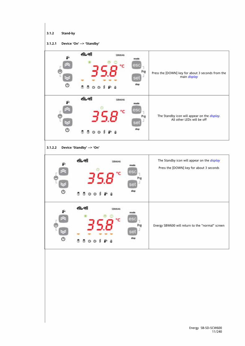
3.1.2.1 Device ‘On’ --> ‘Standby’
Press the [DOWN] key for about 3 seconds from the
main display
The Standby icon will appear on the display. All other LEDs will be off
3.1.2.2 Device ‘Standby’ --> ‘On’
The Standby icon will appear on the display
Press the [DOWN] key for about 3 seconds
Energy SBW600 will return to the "normal" screen

Energy SB-SD-SCW600 12/240
<IMG INFO> 56,7 54,2 1 2 51 -27,1 -1
3.1.3 Description of keys - combined action Symbol
[function associated to
combined operation of
the keys]
Key combination
Combined press Single press (press and release
[associated function]
[Menu] / Comments
[UP +
DOWN] [Activate/Deactivate]
See paragraph on Time Bands
Time Bands / Reset
depending on model
[Open Programming menu]
[Esc +
Set]
[Programming menu]
3.1.3.3 Manual alarm acknowledgment and reset Alarm messages blink. How to acknowledge an alarm is explained below. All error messages are shown in the AL folder (see States Menu)
An error message will be shown, alternating with the error alert...
...and the main display.
The ALARM LED will be permanently on.
IMG INFO

Energy SB-SD-SCW600 13/240
ALARM ACKNOWLEDGMENT
An error can be acknowledged by pressing any key once.
After pressing any key, the alarm LED will start to
blink.
MANUAL RESET
See Functions chapter Manual Reset paragraph
3.2 LEDs and Display The display has 18 icons (LEDs) split into 3 categories:
States and Operating Modes Values and Units of Measure Utilities
3.2.1 Display Values of up to 4 digits or 3 digits plus a sign can be displayed.
3.2.2 LEDs: decimal point Values are always shown in tenths of a degree/bar

Energy SB-SD-SCW600 14/240
3.2.3 LEDs: States and Operating Modes LED states and Operating Modes
icon description Colour Permanently
on Blinking
Alarm red Active alarm Alarm acknowledged
Heating* Heating mode
Antifreeze with heat pump active
Remote heating mode
Cooling* Cooling mode Remote cooling mode
Standby* Local standby mode (from keyboard)
Remote standby
Defrost Defrost active Manual defrost activated
The display shows the value/resource set for the "main display". In the event of an alarm, it will alternate with the alarm code Exx. (when more than one alarm occurs at the same time, the one with the lowest number will be shown - see Alarms and Diagnostics chapter)
Economy
green
Configurable ----
See Parameters chapter
---- Ui /dS folder
Parameters UI07 /dS00
Configurable ----
See Parameters chapter ----
Ui /dS folder Parameters UI07 /dS00
*In AS (sanitary water) mode the Mode LED is OFF
3.2.4 LEDs: Values and Units of Measure
LED Unit of measure icon description Colour Permanently on Blinking
Clock (RTC)
--- Time Bands
red
Shows current time
(24hr format)
--- Time Bands enabled
Set time
--- Program Time
Bands
Degrees centigrade / /
Pressure (Bar)
/ /
Relative humidity (% RH)
Not used Not used
Values can be displayed with a decimal point by setting parameter Ui08 (see parameters chapter, Ui folder)
Menu (ABC)
Menu navigation /
<IMG INFO> 122,45 70,45 0 2 141,9 0 -1
IMG INFO
<IMG INFO> 122,45 67,9 0 2 0,35 6,3 -1
IMG INFO
IMG INFO

Energy SB-SD-SCW600 15/240
<IMG INFO> 42,85 29,75 1 2 48,4 21 5
<IMG INFO> 42,85 29,75 1 2 48,4 23 5
3.2.5 LEDs: utilities
LED utilities description Colour Permanently on Blinking
utility amber
Configurable (°) ----
See Parameters chapter
---- Ui folder
Parameters UI00..UI06
Configurable (°°) ----
See Parameters chapter
---- Ui folder
Parameters UI00..UI06
(°) permanently on: utility active (°°) blinking: UI00..UI06= 50…53 (power steps 1…4) indicates safety timing Note: In the case of LED configured as sanitary water valve, the LED blinks when AS mode is enabled but not active. Permanently on when serving a sanitary water request Default configuration LEDs for utilities are all configurable (see parameters chapter, folder Ui). The factory settings are listed in the table below:
LED symbol on display
LEDs Default SBW600
default icon on front panel SBW600
LED 1 (first from left)
Power step 1
LED 2
Power step 2
LED 3 Internal circuit water pump 1 LED 4 External circuit water pump LED 5 Internal exchanger electric heater
LED 6 Sanitary water valve / pump LED 7 Boiler
3.3 First switch on
When Energy SBW600 is powered on for the first time, a lamp test is carried out to check its state and operation.
---------- The Lamp Test lasts for a few seconds. During this short time, all LEDs and digits flash at the same time.
After the lamp test, based on preselected settings, the following are displayed:
The time, the real setpoint the parameter setpoint the value of the analogue input selected
(AIL1…AIL5) ----------
In the example, the main display is the real set point
<IMG INFO> 122,45 72,95 0 2 -2 5,75 -1

Energy SB-SD-SCW600 16/240
3.4 Access to folders - menu structure Access to folders is organised into menus. Access is determined by the keys on the front panel (see relative sections). Access to each individual menu is explained below (or in the sections indicated). There are 4 menus:
Main Display Menu → See Main Display Menu section Operating Mode menu → see Operating Mode Menu section States Menu → See States Menu section Programming Menu → See Programming Menu section
There are 4 folders/submenus in the Programming Menu:
Parameters Menu (Par folder) → see Parameters chapter; Functions Menu (Fnc folder) → see Functions chapter; Password PASS Alarm codes EU
3.4.1 Main Display Menu The Main Display refers to the contents of the default display, i.e. when keys are not used.
Ai AIL1 AIL2 AIL3 AIL4 AIL5 AIE1 AIE2 AIE3 AIE4 AIE5 Air1 Air2
rtC HH:MM SetP SetP
Main Display
Setr Setr In Energy SBW600, the main display can be customized to suit personal requirements. The various contents can be selected from the "disp" menu which is opened by pressing and holding the [set] key for more than 3 seconds. The main display can be selected from:
analogue inputs AiL1, AiL2, AiL3, AiL4, AiL5, AiE1, AiE2, AiE3, AiE4, AiE5, Air1, Air2 when configured as digital inputs
- 0 or 0.0 = input not active (equivalent to input shortcircuited to ground) - 1 or 0.1 = input active (equivalent to input open)
rtC, Setpoint
o SetP= set from parameter o Setr= real with any decalibration;
Step by step instructions are provided below.
To open the [disp] menu to modify the main display setup, press and hold the set key for at
least 3 seconds. [set]
This opens the blinking menu for the previous display (in this case rtC, i.e. current time).
Energy SB-SD-SCW600 17/240
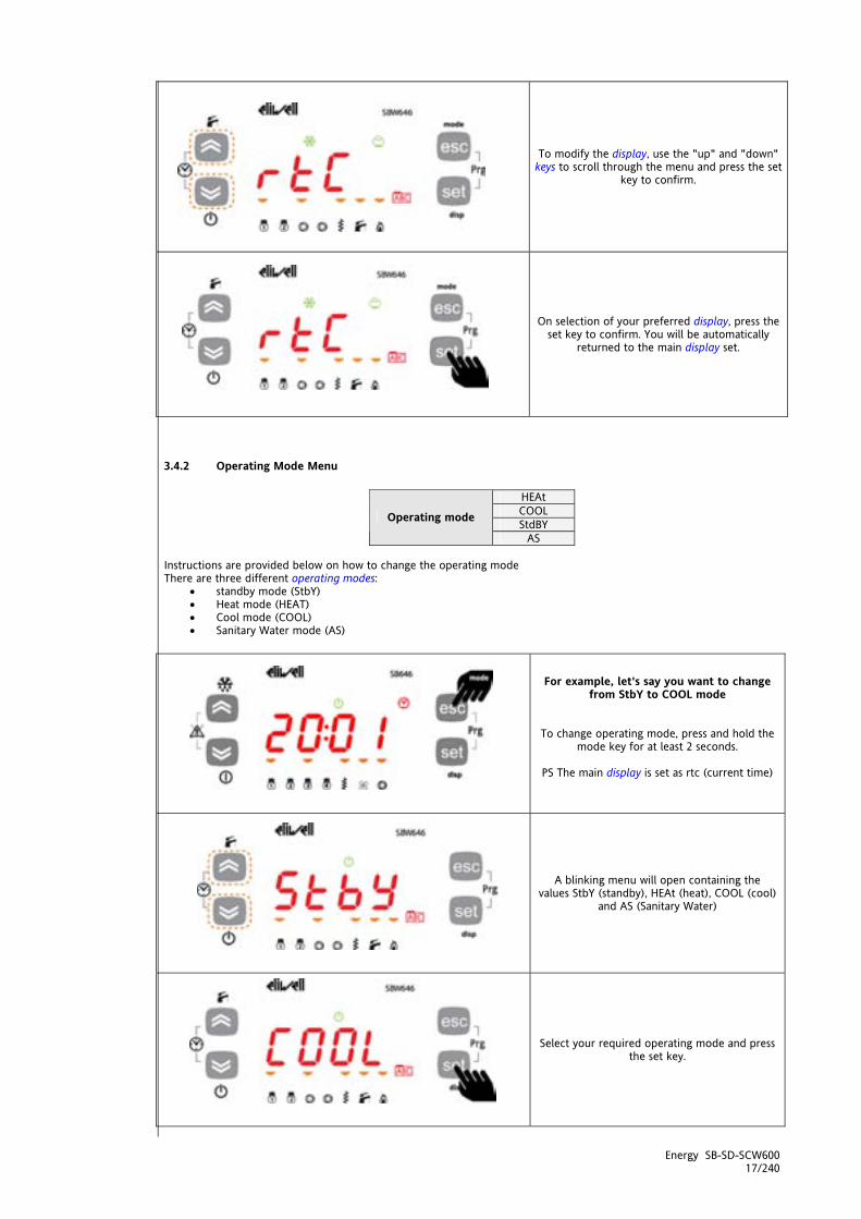
To modify the display, use the "up" and "down" keys to scroll through the menu and press the set
key to confirm.
On selection of your preferred display, press the set key to confirm. You will be automatically
returned to the main display set.
3.4.2 Operating Mode Menu
HEAt COOL StdBY Operating mode
AS Instructions are provided below on how to change the operating mode There are three different operating modes:
standby mode (StbY) Heat mode (HEAT) Cool mode (COOL) Sanitary Water mode (AS)
For example, let's say you want to change from StbY to COOL mode
To change operating mode, press and hold the mode key for at least 2 seconds.
PS The main display is set as rtc (current time)
A blinking menu will open containing the values StbY (standby), HEAt (heat), COOL (cool)
and AS (Sanitary Water)
Select your required operating mode and press the set key.
IMG INFO
<IMG INFO>

Energy SB-SD-SCW600 18/240
You will be automatically returned to the main display and you will see that the Stby LED that was previously on has gone off and the COOL
LED has come on
3.4.3 States Menu From the states menu you can view the values of each resource. For some resources, a "dynamic" view is possible:
For example, when declared as not present / probe not configured (see System Configuration chapter (folder Par/CL), parameter CL01=0), analogue input AIL2 will not be displayed
For example the hours of functioning of compressor 2 - CP02 - not available on single compressor machines The resources may be present / not present depending on the model (e.g. dOL6 is only present on the SBW655) folder Visibility description change
Ai AIL1 AiL2 AIL3 AIL4 AIL5 Dynamic LOCAL analogue inputs
//
Ai AIE1 AiE2 AIE3 AIE4 AIE5 Dynamic EXTENDED analogue inputs(§)
//
Ai Air1 Air2 Dynamic REMOTE TERMINAL analogue inputs
//
di diL1 diL2 diL3 diL4 diL5 diL6 // Dynamic LOCAL Digital inputs //
di diE1 diLE2 diE3 diE4 diE5 diE6 // Dynamic EXTENDED analogue inputs(§) //
AO tCL1 AOL1 AOL2 AOL3 AOL4 AOL5 // Dynamic LOCAL Analogue outputs
//
AO tCE1 AOE1 AOE2 AOE3 AOE4 AOE5 // Dynamic EXTENDED analogue outputs(§) //
dO dOL1 dOL2 dOL3 dOL4 dOL5 dOL6 // Dynamic LOCAL Digital outputs
//
dO dOE1 dOE2 dOE3 dOE4 dOE5 dOE6 // Dynamic EXTENDED digital outputs(§) //
CL HOUr dAtE YEAr Clock YES AL Er00 …. … … … Er97 Er98 Dynamic Alarms // SP Value // // // // // // setpoint (set) YES Sr Value // // // // // // real setpoint // Hr CP01 CP02 CP03 CP04 PU01 PU02 PU03 Dynamic Tens of hours of
operation compressors/pumps
YES
(§) only if SE600 expansion module present As you will be able to see from the table, the setpoint SP and time can be modified and viewed:
3.4.3.1 Display Inputs/Outputs (AiL, diL, tCL1/AOL, dOL)
Press the set key from the main display
IMG INFO IMG INFO

Energy SB-SD-SCW600 19/240
Example of display of Analogue Inputs. The same procedure applies for all other I/Os***
The label Ai will appear on the display.
(Use the UP and DOWN keys to scroll through the
other labels until you find the label required)
Press the set key to view the label for the first analogue input (AiL1 in this case)
Press the set key again to view the value of AiL1. Note that the °C icon lights up to indicate that the
value shown is in degrees centigrade
***For digital inputs/analogue inputs configured as digital, the value will be:
- 0 = input not active (for digital inputs this is equivalent to input open, for analogue inputs configured as digital to input shortcircuited to ground)
- 1 = input active (for digital inputs this is equivalen to input shortcircuited to ground, for analogue inputs configured as digital to input open) -------------------------------------
Press the esc key to go back to the main display.
3.4.3.2 Setting the clock (CL) The Energy SBW600 has a clock (RTC) to run the alarm log and time bands, just like a programmable timer thermostat. Instructions are provided below on how to set the time: the same procedure applies to change the date and year.
To change the clock on your machine, press the set key from the main display.
Pressing the set key once will open a list of the various folders.
Use the “UP” and “DOWN” keys to find the CL folder.
<IMG INFO>
<IMG INFO>

Energy SB-SD-SCW600 20/240
Press the set key to open the CL menu.
On entering this menu, you will see HOUr. Use the “UP” and “DOWN” keys to select the time,
date or year. Once you have decided what you want to set, press the [set]** key to open the modification
menu for the variable selected. **press and hold for about 3 seconds
To set the time, date and year, use the "UP" and "DOWN" keys to enter the required value,
then...
... press set.
IMG INFO

Energy SB-SD-SCW600 21/240
Press the Esc key repeatedly to exit the set clock menu and go back to the main display.
IMG INFO

Energy SB-SD-SCW600 22/240
3.4.3.3 Alarm Display (AL)
Press the set key from the main display
The label Ai will appear on the display. Use the UP and DOWN keys to browse the other labels until you
find the AL label
Press the set key to view the label of the first active alarm (if it exists)
In this case, the first alarm is Er01. Use the UP and DOWN keys to scroll any other alarms.
------------------------------------- NOTE: the menu is not cyclical.
For example, if the active alarms are Er01, Er02 and Er03, the display will show
Er01 ->Er02->Er03 <-Er02<-Er01
NOTE: -> UP, <-DOWN Press the esc key repeatedly to go back to the main
display.
<IMG INFO>;226,55;90,95;0;2;99,15;0;-1;212,25;84
Energy SB-SD-SCW600 23/240
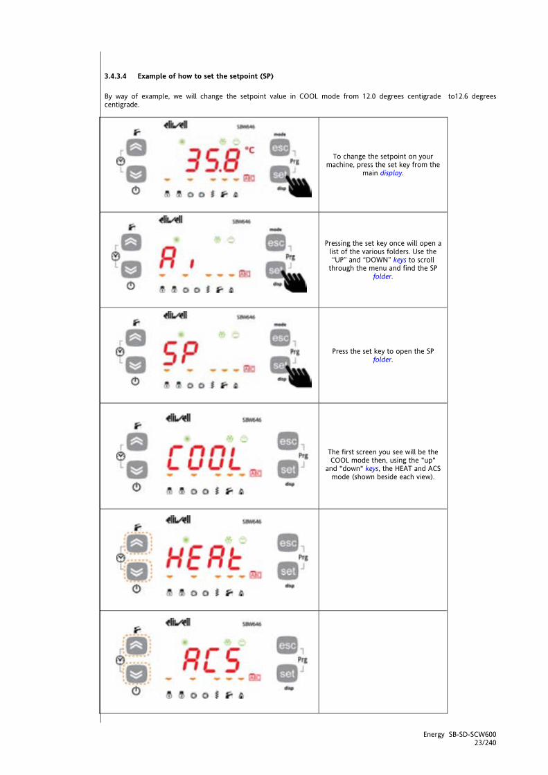
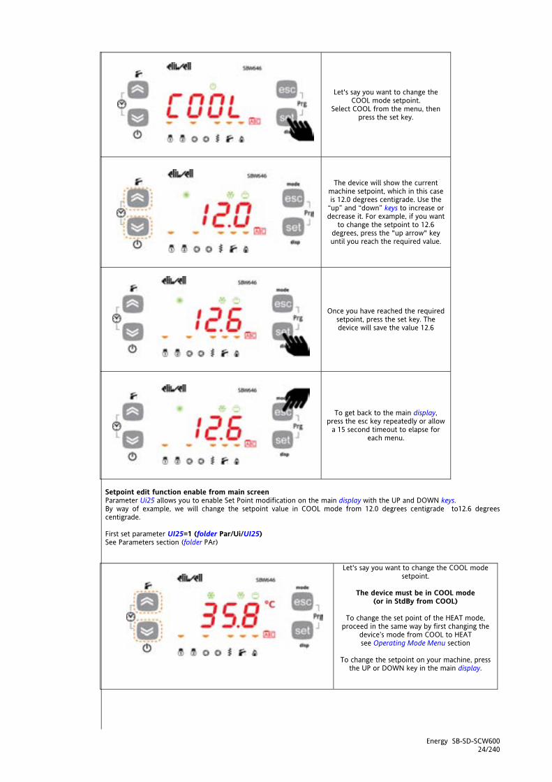
3.4.3.4 Example of how to set the setpoint (SP) By way of example, we will change the setpoint value in COOL mode from 12.0 degrees centigrade to12.6 degrees centigrade.
To change the setpoint on your machine, press the set key from the
main display.
Pressing the set key once will open a list of the various folders. Use the “UP” and “DOWN” keys to scroll
through the menu and find the SP folder.
Press the set key to open the SP folder.
The first screen you see will be the COOL mode then, using the "up"
and "down" keys, the HEAT and ACS mode (shown beside each view).
IMG INFO
Energy SB-SD-SCW600 24/240
Let's say you want to change the COOL mode setpoint.
Select COOL from the menu, then press the set key.
The device will show the current machine setpoint, which in this case is 12.0 degrees centigrade. Use the
“up” and “down” keys to increase or decrease it. For example, if you want
to change the setpoint to 12.6 degrees, press the "up arrow" key until you reach the required value.
Once you have reached the required setpoint, press the set key. The device will save the value 12.6
To get back to the main display, press the esc key repeatedly or allow
a 15 second timeout to elapse for each menu.
Setpoint edit function enable from main screen Parameter Ui25 allows you to enable Set Point modification on the main display with the UP and DOWN keys. By way of example, we will change the setpoint value in COOL mode from 12.0 degrees centigrade to12.6 degrees centigrade. First set parameter UI25=1 (folder Par/Ui/UI25) See Parameters section (folder PAr)
Let's say you want to change the COOL mode setpoint.
The device must be in COOL mode
(or in StdBy from COOL)
To change the set point of the HEAT mode, proceed in the same way by first changing the
device’s mode from COOL to HEAT see Operating Mode Menu section
To change the setpoint on your machine, press
the UP or DOWN key in the main display.
IMG INFO
IMG INFO

Energy SB-SD-SCW600 25/240
The device will show the current machine setpoint, which in this case is 12.0 degrees
centigrade.
Use the “up” and “down” keys to increase or decrease it
For example, if you want to change the setpoint to 12.6 degrees, press the "up arrow" key until
you reach the required value.
Once you have reached the required setpoint, press the set key. The device will save the value
12.6
IMG INFO
IMG INFO

Energy SB-SD-SCW600 26/240
3.4.3.5 Display and reset compressor/pump hours
Example display and reset (tens of) hours for Pump 2
Press the set key from the main display
The label Ai will appear on the display. Use the UP and DOWN keys to scroll through the other labels
until you find the Hr label
Press the set key to view the first label - which in this case is the running time for compressor 1 (CP01)
Scroll with the UP and DOWN keys to view (if the relative resources are present) the running time for compressor 2 (CP02) and the pump running time
(PU01, PU02, PU03)
Press the set key to view the pump running time PU02
The tens of hours of functioning are 2.
(Hours expressed in tens: 2 means 20 hours of operation)
To reset the hours of functioning of pump PU02,
press and hold [set] Note: repeat the above procedure to reset the hours
of functioning of the other resources
------------------------------------- Press the esc key repeatedly to go back to the main
display.

Energy SB-SD-SCW600 27/240
3.4.4 Programming menu
Menu folder description comments Parameters PAr CL Cr CF Ui St … Al parameters
Functions FnC dEF tA tA tA St CC EUr functions See Functions chapter (folder
FnC) Passwords PASS password
EU EU Eu00 … … … … … …
3.4.4.6 Parameters (folder PAr) Modifying a parameter Instructions are provided below on how to change a machine parameter. By way of example, let's look at the CL configuration parameters folder, parameter CL01 (folder PAr/CL/CL01).
Press the esc and set keys together to open the parameters menu. This will open the PAr menu.
The PAr parameters menu contains all device parameter folders. Press the set key to view all
folders.
The first folder the controller shows is the CL configuration folder. Simply press the set key again to
modify individual CL parameters.
The CL00 parameter will be shown on the device (factory default settings).
Press the "up" key to scroll through the various
parameters or move to the next parameter (CL01 in this case) or the “down” key to go back to the
previous parameter (CL97 in this case)
CF00->CF01->CF02->…->CL97->CL00 CL97<-CL00<-CL01->…<-CL96<-CL97
NOTE: -> UP, <-DOWN
<IMG INFO>

Energy SB-SD-SCW600 28/240
Press the set key to view the value of the parameter (CL01 in this case).
For parameter CL01, the value shown will be 2. Press the “up” and “down” keys to modify this value.
Press the set key once you have entered the required value. ** Press the esc key to exit this display and go back to the previous level.
**N.B. pressing the set key will confirm the value entered; pressing the esc key will take you back to the
previous level without saving the value entered
3.4.5 Functions (Par/FnC folder) See Functions chapter (folder FnC)
3.4.6 Entering a password (Par/PASS folder) Levels of visibility Four levels of visibility can be set by assigning suitable values to each parameter and folder, by serial, software (DeviceManager or other communication softwares) or by programming key The visibility levels are:
Value 3 = parameter or folder always visible; Value 2 = manufacturer level; these parameters can only be seen by entering the manufacturer's password
(see parameter Ui28) (all parameters specified as always visible, parameters that are visible at the installation level, and manufacturer level parameters will be visible)
Value 1 = installation level; these parameters can only be viewed by entering the installation password (see parameter Ui27) (all parameters specified as always visible and parameters that are visible at the installation level will be visible)
Value 0 = parameter or folder NOT visible
1. Parameters and/or folders with visibility level <>3 (i.e. password protected) will only be visible if the correct password is entered (installer or manufacturer) following the procedure outlined below:
2. Parameters and/or folders with visibility level =3 are always visible and no password is required; in this case, the procedure below is not required.
IMG INFO

Energy SB-SD-SCW600 29/240
To view parameters visible for the given password, open folder PASS (press esc and set together [esc+set] from the main display and search the folder using the up/down keys) and set the PASS value
Press the esc and set keys together from the main display to enter the PASS folder. [esc+set]
Pressing the two keys will open the menu containing the list of folders. Use the “up” and “down” keys to scroll through the list until you find the PASS folder.
Press the set key to open the PASS folder. Enter the password (installation or manufacturer)
from here, press the set key and exit.
Now access the parameters to display and change their values (see parameters chapter)
3.4.7 Alarm events (Par/EU folder)
To view folder PAr from the main display, press the Esc and Set keys at the same time. [esc+set]
Pressing the two keys will open the menu containing the list of folders. Use the “up” and
“down” keys to find the EU folder
Press set to view the last alarm event - if it exists - EU00.
NB: EU00 indicates the last alarm recorded, EU01 the second last, and so on.
Scroll with the UP and DOWN keys to view (if
present) any other alarm events
IMG INFO
IMG INFO
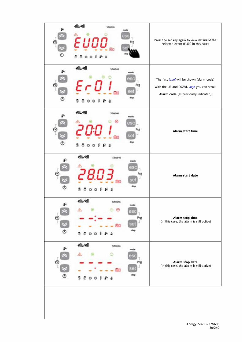
Energy SB-SD-SCW600 30/240
Press the set key again to view details of the selected event (EU00 in this case)
The first label will be shown (alarm code)
With the UP and DOWN keys you can scroll:
Alarm code (as previously indicated)
Alarm start time
Alarm start date
Alarm stop time (in this case, the alarm is still active)
Alarm stop date (in this case, the alarm is still active)
IMG INFO

Energy SB-SD-SCW600 31/240
Type of alarm
(automatic)
or alternatively
(manual)

Energy SB-SD-SCW600 32/240
<IMG INFO> 56,75 43,9 1 2 51 -28,35 -1
4 SYSTEM CONFIGURATION (FOLDER PAR/CF) Before doing anything, make sure the device is connected to a suitable external transformer. The following rules must be followed when connecting cards to each other and to the application:
Loads that exceed the maximum limits set forth herein must not be applied to outputs; When connecting loads, follow connection diagrams carefully; To avoid electric pairings, wire all SELV (*) utilities separately from high voltage ones.
(*) SELV: SAFETY EXTRA LOW VOLTAGE Instrument configuration is determined by the values of the parameters associated with the inputs and outputs.
4.1 Configuration of analogue inputs The analogue inputs referred to below as AiL1…AiL5 are 5 in total. Using the parameters, a physical resource (probe, digital input, voltage/current signal) can be "physically" configured for each type of input:
3 inputs can be configured as temperature probes, an NTC type probe, or as digital inputs 2 inputs (AiL3 and AiL4) can be configured as temperature probes, an NTC type probe, as digital inputs or
current/voltage input (signal 4-20mA / 0-10V, 0-5V, 0-1V)
4.1.1 Configuration of SE600 expansion analogue inputs The analogue inputs referred to below as AiE1…AiE5 are 5 in total. Using the parameters, - a physical resource (sensor, digital input, voltage/current signal) can be "physically" configured for each type of input:
3 inputs can be configured as temperature sensors, an NTC type sensor, or as digital inputs 2 inputs (AiE3 AiE4) can be configured as temperature sensors, an NTC type sensor, digital inputs or as a
voltage/current input (signal 4-20mA / 0-10V, 0-5V, 0-1V)
4.1.2 Configuring SKW remote terminal analogue inputs The analogue inputs referred to below as AIR1…AIR2 are 2 in total. Using the parameters, a physical resource (probe, digital input, voltage/current signal) can be "physically" configured for each type of input:
1 input configurable as NTC type temperature probe 1 input configurable as NTC type temperature probe, digital input or current input (4-20mA signal)
Using parameters, a logical meaning can be given to each analogue input Inputs can be "physically" configured as specified in the table below.
Value Parameter Description
0 1 2 3 4 5 6
CL00 AiL1 type analogue input
Probe not configured
Probe configured as no voltage digital input NTC probe // // // //
CL01 AiL2 type analogue input
Probe not configured
Probe configured as no voltage digital input NTC probe // // // //
CL02 AiL3 type analogue input
Probe not configured
Probe configured as no voltage digital input NTC probe 4-20 mA 0-10 V 0-5 V 0-1 V
CL03 AiL4 type analogue input
Probe not configured
Probe configured as no voltage digital input NTC probe 4-20 mA 0-10 V 0-5 V 0-1 V
CL04 AiL5 type analogue input
Probe not configured
Probe configured as no voltage digital input NTC probe // // // //
CE01 AiE2 type analogue input
Probe not configured
Probe configured as no voltage digital input NTC probe // // // //
CE02 AiE3 type analogue input
Probe not configured
Probe configured as no voltage digital input NTC probe 4-20 mA 0-10 V 0-5 V 0-1 V
CE03 AE4 type analogue input
Probe not configured
Probe configured as no voltage digital input NTC probe 4-20 mA 0-10 V 0-5 V 0-1 V
CE04 AiE5 type analogue input
Probe not configured
Probe configured as no voltage digital input NTC probe // // // //
CE00 AiE1 analogue input type
Sensor not configured
Sensor configured as no voltage digital input NTC sensor // // // //
CE01 AiE2 analogue input type
Sensor not configured
Sensor configured as no voltage digital input NTC sensor // // // //
CE02 AiE3 analogue input type
Sensor not configured
Sensor configured as no voltage digital input NTC sensor 4-20 mA 0-10 V 0-5 V 0-1 V
CE03 AiE4 analogue input type
Sensor not configured
Sensor configured as no voltage digital input NTC sensor 4-20 mA 0-10 V 0-5 V 0-1 V
CE04 AiE5 analogue input type
Sensor not configured
Sensor configured as no voltage digital input NTC sensor // // // //
Parameter Description Value
0 1 2 3
SBW SDW SCW 600 Analogue
inputs
SE600 analogue inputs
SKW Analogue inputs
Analogue inputs: Configuration
table

Energy SB-SD-SCW600 33/240
Cr00 AIr1 type analogue input
Probe not configured // NTC probe //
Cr01 Air2 type analogue input
Probe not configured
Probe configured as no voltage digital input NTC probe 4…20mA
See Configuration of digital inputs
NOTE: // indicates that value is not present
Analogue input AI Parameter range Description AiL3 CL10 CL11…99.9 Analogue input AiL3 full scale value AiL3 CL11 -50.0…CL10 Analogue input AiL3 start of scale value AiL4 CL12 CL13…99.9 Analogue input AiL4 full scale value AiL4 CL13 -50.0…CL12 Analogue input AiL4 start of scale value AiE3 CE10 CE11…99.9 Analogue input AiE3 full scale value AiE3 CE11 -50.0…CE10 Analogue input AiE3 start of scale value AiE4 CE12 CE13…99.9 Analogue input AiE4 full scale value AiE4 CE13 -50.0…CE12 Analogue input AiE4 start of scale value
Air1 Cr10 CR11…99.9 Analogue input Air2 full scale value Air2 Cr11 -50.0…CR10 Analogue input Air2 start of scale value
The values read by analogue inputs can be calibrated using parameters CL20…CL24 / Cr20…Cr21
Parameter Description Measurement Unit range CL20 Analogue input AiL1 differential °C -12.0..12.0 CL21 Analogue input AiL2 differential °C -12.0..12.0 CL22 Analogue input AiL3 differential °C / Bar -12.0..12.0 CL23 Analogue input AiL4 differential °C / Bar -12.0..12.0 CL24 Analogue input AiL5 differential °C -12.0..12.0 CE20 Analogue input AiE1 differential °C -12.0..12.0 CE21 Analogue input AiE2 differential °C -12.0..12.0 CE22 Analogue input AiE3 differential °C / Bar -12.0..12.0 CE23 Analogue input AiE4 differential °C / Bar -12.0..12.0 CE24 Analogue input AiE5 differential °C -12.0..12.0 Parameter Description Measurement Unit range Cr20 Analogue input Air1 differential °C -12.0..12.0 Cr21 Analogue input Air2 differential °C / Bar -12.0..12.0
See the following tables: Table A - parameter association - configuration of analogue inputs
Parameter Description value Description Notes
CL30 Configuration of analogue input AiL1 0…16 See table B If CL00=1 (AiL1 configured as DI) set CL30=0
CL31 Configuration of analogue input AiL2 0…16 See table B If CL01=1 (AiL2 configured as DI) set CL31=0
CL32 Configuration of analogue input AiL3 0…30 See table B If CL02=1 (AiL3 configured as DI) set CL32=0
CL33 Configuration of analogue input AiL4 0…30 See table B If CL03=1 (AiL4 configured as DI) set CL33=0
CL34 Configuration of analogue input AiL5 0…16 See table B If CL04=1 (AiL5 configured as DI) set CL34=0
CE30 Configuration of analogue input AiE1 0…16 See table B If CE00=1 (AiE1 configured as DI) set CE30=0
CE31 Configuration of analogue input AiE2 0…16 See table B If CE01=1 (AiE2 configured as DI) set CE31=0
CE32 Configuration of analogue input AiE3 0…30 See table B If CE02=1 (AiE3 configured as DI) set CE32=0
CE33 Configuration of analogue input AiE4 0…30 See table B If CE03=1 (AiE4 configured as DI) set CE33=0
CE34 Configuration of analogue input AiE5 0…16 See table B If CE04=1 (AiE5 configured as DI) set CE34=0
Parameter Description value Description Notes
CR30 Configuration of analogue input Air1 0…15 See table B
CR31 Configuration of analogue input Air2 0…29 See table B If CR01=1 (AIR2 configured as DI), set CR31=0
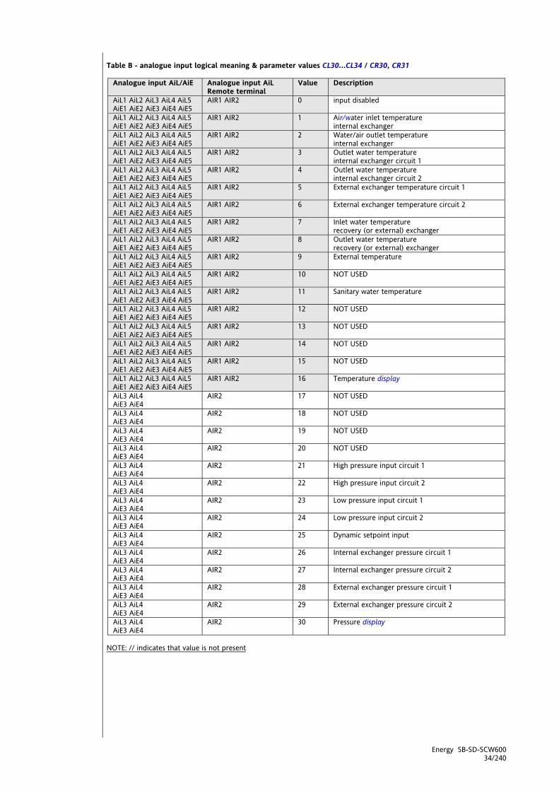
Energy SB-SD-SCW600 34/240
Table B - analogue input logical meaning & parameter values CL30…CL34 / CR30, CR31
Analogue input AiL/AiE Analogue input AiL Remote terminal
Value Description
AiL1 AiL2 AiL3 AiL4 AiL5 AiE1 AiE2 AiE3 AiE4 AiE5
AIR1 AIR2 0 input disabled
AiL1 AiL2 AiL3 AiL4 AiL5 AiE1 AiE2 AiE3 AiE4 AiE5
AIR1 AIR2 1 Air/water inlet temperature internal exchanger
AiL1 AiL2 AiL3 AiL4 AiL5 AiE1 AiE2 AiE3 AiE4 AiE5
AIR1 AIR2 2 Water/air outlet temperature internal exchanger
AiL1 AiL2 AiL3 AiL4 AiL5 AiE1 AiE2 AiE3 AiE4 AiE5
AIR1 AIR2 3 Outlet water temperature internal exchanger circuit 1
AiL1 AiL2 AiL3 AiL4 AiL5 AiE1 AiE2 AiE3 AiE4 AiE5
AIR1 AIR2 4 Outlet water temperature internal exchanger circuit 2
AiL1 AiL2 AiL3 AiL4 AiL5 AiE1 AiE2 AiE3 AiE4 AiE5
AIR1 AIR2 5 External exchanger temperature circuit 1
AiL1 AiL2 AiL3 AiL4 AiL5 AiE1 AiE2 AiE3 AiE4 AiE5
AIR1 AIR2 6 External exchanger temperature circuit 2
AiL1 AiL2 AiL3 AiL4 AiL5 AiE1 AiE2 AiE3 AiE4 AiE5
AIR1 AIR2 7 Inlet water temperature recovery (or external) exchanger
AiL1 AiL2 AiL3 AiL4 AiL5 AiE1 AiE2 AiE3 AiE4 AiE5
AIR1 AIR2 8 Outlet water temperature recovery (or external) exchanger
AiL1 AiL2 AiL3 AiL4 AiL5 AiE1 AiE2 AiE3 AiE4 AiE5
AIR1 AIR2 9 External temperature
AiL1 AiL2 AiL3 AiL4 AiL5 AiE1 AiE2 AiE3 AiE4 AiE5
AIR1 AIR2 10 NOT USED
AiL1 AiL2 AiL3 AiL4 AiL5 AiE1 AiE2 AiE3 AiE4 AiE5
AIR1 AIR2 11 Sanitary water temperature
AiL1 AiL2 AiL3 AiL4 AiL5 AiE1 AiE2 AiE3 AiE4 AiE5
AIR1 AIR2 12 NOT USED
AiL1 AiL2 AiL3 AiL4 AiL5 AiE1 AiE2 AiE3 AiE4 AiE5
AIR1 AIR2 13 NOT USED
AiL1 AiL2 AiL3 AiL4 AiL5 AiE1 AiE2 AiE3 AiE4 AiE5
AIR1 AIR2 14 NOT USED
AiL1 AiL2 AiL3 AiL4 AiL5 AiE1 AiE2 AiE3 AiE4 AiE5
AIR1 AIR2 15 NOT USED
AiL1 AiL2 AiL3 AiL4 AiL5 AiE1 AiE2 AiE3 AiE4 AiE5
AIR1 AIR2 16 Temperature display
AiL3 AiL4 AiE3 AiE4
AIR2 17 NOT USED
AiL3 AiL4 AiE3 AiE4
AIR2 18 NOT USED
AiL3 AiL4 AiE3 AiE4
AIR2 19 NOT USED
AiL3 AiL4 AiE3 AiE4
AIR2 20 NOT USED
AiL3 AiL4 AiE3 AiE4
AIR2 21 High pressure input circuit 1
AiL3 AiL4 AiE3 AiE4
AIR2 22 High pressure input circuit 2
AiL3 AiL4 AiE3 AiE4
AIR2 23 Low pressure input circuit 1
AiL3 AiL4 AiE3 AiE4
AIR2 24 Low pressure input circuit 2
AiL3 AiL4 AiE3 AiE4
AIR2 25 Dynamic setpoint input
AiL3 AiL4 AiE3 AiE4
AIR2 26 Internal exchanger pressure circuit 1
AiL3 AiL4 AiE3 AiE4
AIR2 27 Internal exchanger pressure circuit 2
AiL3 AiL4 AiE3 AiE4
AIR2 28 External exchanger pressure circuit 1
AiL3 AiL4 AiE3 AiE4
AIR2 29 External exchanger pressure circuit 2
AiL3 AiL4 AiE3 AiE4
AIR2 30 Pressure display
NOTE: // indicates that value is not present

Energy SB-SD-SCW600 35/240
4.2 Configuration of digital inputs The no voltage digital inputs referred to below as DI1…DI6 are 6 in total These can be added to by AiL1…AiL5 if the latter are configured as digital inputs (via parameters CL50…5L4+CR50 respectively). Hence a total of 11+1 digital inputs are available. See the following tables: Table A - parameter association - configuration of digital inputs Parameter Description value Description Notes
CL40 Configuration of digital input DIL1 -58…+58 See table B CL41 Configuration of digital input DIL2 -58…+58 See table B CL42 Configuration of digital input DIL3 -58…+58 See table B CL43 Configuration of digital input DIL4 -58…+58 See table B CL44 Configuration of digital input DIL5 -58…+58 See table B CL45 Configuration of digital input DIL6 -58…+58 See table B
CL50 Configuration of analogue input AiL1 if configured as a digital input -58…+58 See table B Set to 0 if AiL1 is NOT
configured as a DI
CL51 Configuration of analogue input AiL2 if configured as a digital input -58…+58 See table B Set to 0 if AiL2 is NOT
configured as a DI
CL52 Configuration of analogue input AiL3 if configured as a digital input -58…+58 See table B Set to 0 if AiL3 is NOT
configured as a DI
CL53 Configuration of analogue input AiL4 if configured as a digital input -58…+58 See table B Set to 0 if AiL4 is NOT
configured as a DI
CL54 Configuration of analogue input AiL5 if configured as a digital input -58…+58 See table B Set to 0 if AiL5 is NOT
configured as a DI CE40 Configuration of digital input DIE1 -58…+58 See table B CE41 Configuration of digital input DIE2 -58…+58 See table B CE42 Configuration of digital input DIE3 -58…+58 See table B CE43 Configuration of digital input DIE4 -58…+58 See table B CE44 Configuration of digital input DIE5 -58…+58 See table B CE45 Configuration of digital input DIE6 -58…+58 See table B
CE50 Configuration of analogue input AiE1 if configured as a digital input -58…+58 See table B Set to 0 if AiE1 is NOT
configured as a DI
CE51 Configuration of analogue input AiE2 if configured as a digital input -58…+58 See table B Set to 0 if AiE2 is NOT
configured as a DI
CE52 Configuration of analogue input AiE3 if configured as a digital input -58…+58 See table B Set to 0 if AiE3 is NOT
configured as a DI
CE53 Configuration of analogue input AiE4 if configured as a digital input -58…+58 See table B Set to 0 if AiE4 is NOT
configured as a DI
CE54 Configuration of analogue input AiE5 if configured as a digital input -58…+58 See table B Set to 0 if AiE5 is NOT
configured as a DI Parameter Description value Description Notes
CR50 Configuration of analogue input AIR2 if configured as a digital input -58…+58 See table B** Set to 0 if AIR2 is NOT
configured as a DI Table B - Digital inputs: Configuration table Polarity is defined below:
Value Description + Positive Active when contact closed - Negative Active when contact open
Value Description Notes 0 Input disabled ±1 Remote STD-BY ±2 Remote OFF Local ON/OFF ineffective ±3 Remote Summer/Winter ±4 Power step 1 request ±5 Power step 2 request ±6 Power step 3 request ±7 Power step 4 request ±8 Digital input heat step 1 request See also digital temperature control ±9 Digital input heat step 2 request See also digital temperature control ±10 Digital input heat step 3 request See also digital temperature control ±11 Digital input heat step 4 request See also digital temperature control ±12 Digital input cool step 1 request See also digital temperature control ±13 Digital input cool step 2 request See also digital temperature control ±14 Digital input cool step 3 request See also digital temperature control ±15 Digital input cool step 4 request See also digital temperature control ±16 Block compressor 1
Digital inputs
Digital inputs: Configuration
table

Energy SB-SD-SCW600 36/240
Value Description Notes ±17 Block compressor 2 ±18 Block compressor 3 ±19 Block compressor 4 ±20 Block heat pump See section
Block heat pump (folder PAr/HP) ±21 Power stage forced to 50% See section
Forced power stage (folder PAr/PL) ±22 Economy input See section
Operating modes - Temperature control (folder PAr/tr)
±23 NOT USED ±24 General alarm ±25 End of defrost C1 ±26 End of defrost C2 ±27 NOT USED ±28 NOT USED ±29 NOT USED ±30 High pressure pressure switch C1 ±31 High pressure pressure switch C2 ±32 Low pressure pressure switch C1 ±33 Low pressure pressure switch C2 ±34 Compressor 1 oil pressure switch ±35 Compressor 2 oil pressure switch ±36 Compressor 3 oil pressure switch ±37 Compressor 4 oil pressure switch ±38 NOT USED ±39 External exchanger fan thermal switch C1 ±40 External exchanger fan thermal switch C2 ±41 Internal exchanger fan thermal switch ±42 NOT USED ±43 Compressor 1 thermal switch ±44 Compressor 2 thermal switch ±45 Compressor 3 thermal switch ±46 Compressor 4 thermal switch ±47 Primary circuit pump 1 thermal switch ±48 Primary circuit pump 2 thermal switch ±49 External circuit pump thermal switch ±50 Internal exchanger electric heater 1 thermal switch ±51 Internal exchanger electric heater 2 thermal switch ±52 Auxiliary output alarm ±53 NOT USED ±54 NOT USED ±55 Primary circuit flow switch ±56 External (recovery) circuit flow switch ±57 NOT USED ±58 Display NOTE: If more than one digital input in the table is configured with the same value, the function is activated when the input with the highest index is piloted
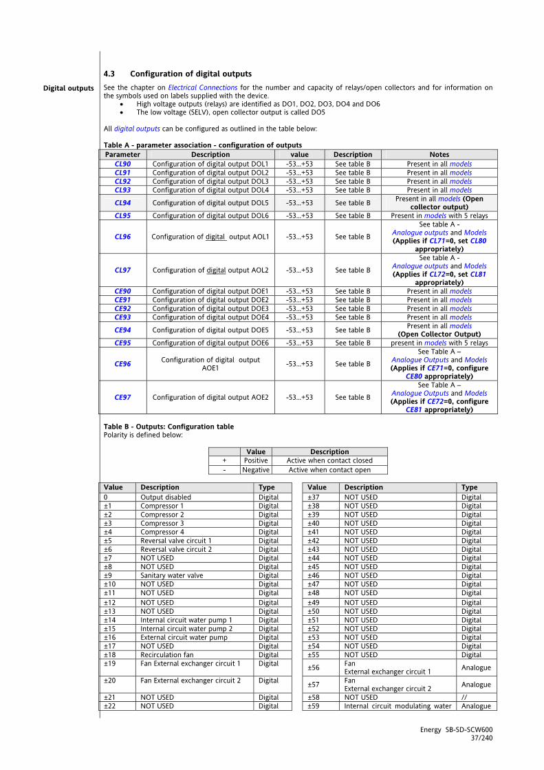
Energy SB-SD-SCW600 37/240
4.3 Configuration of digital outputs See the chapter on Electrical Connections for the number and capacity of relays/open collectors and for information on the symbols used on labels supplied with the device.
High voltage outputs (relays) are identified as DO1, DO2, DO3, DO4 and DO6 The low voltage (SELV), open collector output is called DO5
All digital outputs can be configured as outlined in the table below: Table A - parameter association - configuration of outputs Parameter Description value Description Notes
CL90 Configuration of digital output DOL1 -53…+53 See table B Present in all models CL91 Configuration of digital output DOL2 -53…+53 See table B Present in all models CL92 Configuration of digital output DOL3 -53…+53 See table B Present in all models CL93 Configuration of digital output DOL4 -53…+53 See table B Present in all models
CL94 Configuration of digital output DOL5 -53…+53 See table B Present in all models (Open collector output)
CL95 Configuration of digital output DOL6 -53…+53 See table B Present in models with 5 relays
CL96 Configuration of digital output AOL1 -53…+53 See table B
See table A - Analogue outputs and Models (Applies if CL71=0, set CL80
appropriately)
CL97 Configuration of digital output AOL2 -53…+53 See table B
See table A - Analogue outputs and Models (Applies if CL72=0, set CL81
appropriately) CE90 Configuration of digital output DOE1 -53…+53 See table B Present in all models CE91 Configuration of digital output DOE2 -53…+53 See table B Present in all models CE92 Configuration of digital output DOE3 -53…+53 See table B Present in all models CE93 Configuration of digital output DOE4 -53…+53 See table B Present in all models
CE94 Configuration of digital output DOE5 -53…+53 See table B Present in all models (Open Collector Output)
CE95 Configuration of digital output DOE6 -53…+53 See table B present in models with 5 relays
CE96 Configuration of digital output AOE1 -53…+53 See table B
See Table A – Analogue Outputs and Models (Applies if CE71=0, configure
CE80 appropriately)
CE97 Configuration of digital output AOE2 -53…+53 See table B
See Table A – Analogue Outputs and Models (Applies if CE72=0, configure
CE81 appropriately) Table B - Outputs: Configuration table Polarity is defined below:
Value Description + Positive Active when contact closed - Negative Active when contact open
Value Description Type Value Description Type 0 Output disabled Digital ±37 NOT USED Digital ±1 Compressor 1 Digital ±38 NOT USED Digital ±2 Compressor 2 Digital ±39 NOT USED Digital ±3 Compressor 3 Digital ±40 NOT USED Digital ±4 Compressor 4 Digital ±41 NOT USED Digital ±5 Reversal valve circuit 1 Digital ±42 NOT USED Digital ±6 Reversal valve circuit 2 Digital ±43 NOT USED Digital ±7 NOT USED Digital ±44 NOT USED Digital ±8 NOT USED Digital ±45 NOT USED Digital ±9 Sanitary water valve Digital ±46 NOT USED Digital ±10 NOT USED Digital ±47 NOT USED Digital ±11 NOT USED Digital ±48 NOT USED Digital ±12 NOT USED Digital ±49 NOT USED Digital ±13 NOT USED Digital ±50 NOT USED Digital ±14 Internal circuit water pump 1 Digital ±51 NOT USED Digital ±15 Internal circuit water pump 2 Digital ±52 NOT USED Digital ±16 External circuit water pump Digital ±53 NOT USED Digital ±17 NOT USED Digital ±54 NOT USED Digital ±18 Recirculation fan Digital ±55 NOT USED Digital ±19 Fan External exchanger circuit 1 Digital ±56 Fan
External exchanger circuit 1 Analogue
±20 Fan External exchanger circuit 2 Digital ±57 Fan External exchanger circuit 2 Analogue
±21 NOT USED Digital ±58 NOT USED // ±22 NOT USED Digital ±59 Internal circuit modulating water Analogue
Digital outputs

Energy SB-SD-SCW600 38/240
pump 1 ±23 Electrical heating element 1
internal exchanger Digital ±60 Internal circuit modulating water
pump 2 Analogue
±24 Electrical heating element 2 internal exchanger
Digital ±61 NOT USED Analogue
±25 Electrical heating element External exchanger 1 Digital ±62 Analogue stage 1 for compressor Analogue
±26 Electrical heating element External exchanger 2 Digital ±63 Analogue stage 2 for Compressor Analogue
±27 Auxiliary output Digital ±64 NOT USED Analogue ±28 Sanitary Water Electric Heater Digital ±65 NOT USED Analogue ±29 NOT USED Digital ±66 NOT USED Analogue ±30 Boiler Digital ±67 NOT USED Analogue ±31 Alarm Digital ±68 NOT USED Analogue ±32 NOT USED Digital ±69 NOT USED Analogue ±33 NOT USED Digital ±70 NOT USED* Digital ±34 NOT USED Digital ±71 NOT USED* Digital ±35 NOT USED Digital ±72 NOT USED* Digital ±36 NOT USED Digital ±73 NOT USED* Digital ±74 NOT USED* Digital *see LED Configuration If multiple outputs are configured to run the same resource, the outputs will be activated in parallel.
4.4 Configuration of analogue outputs See the chapter on Electric Connections for the number and type of analogue outputs used and for information on the symbols used on labels supplied with the device. There are 6 analogue outputs. 1 high voltage one and 5 low (SELV) voltage ones, the exact number depending on the following models and with the following characteristics: Table A2 - Analogue outputs and Models
High voltage SELV
Base
mod
els
Expa
nsio
n m
odel
s
output Label
on display
Models 636
Models 646
PWM/ Open
collector 0-10V 0…20mA
4…20mA 636
646
655
632
636
646
655
TC1 TCL1 3A 230V 2A 230V TC2 TCL2 3A 230V AO1 AOL1 AO2 AOL2 AO3 AOL3 AO4 AOL4 AO5 AOL5
TC1 TCE1 3A 230V 2A 230V TC2 TCE2 3A 230V AO1 AOE1 AO2 AOE2 AO3 AOE3 AO4 AOE4 AO5 AOE5
Analogue outputs

Energy SB-SD-SCW600 39/240
Triac analogue outputs (TC1, TC2) High voltage output generally used to pilot fans or water pumps. The output can be configured for proportional operation (continuous speed variation) or as ON/OFF. Remote control switches downstream from the Triac are NOT permitted The TC1 output can be configured as described in the table "Analogue Output TC1 - AO1 AO2: Configuration table” Configuration of low voltage (SELV) analogue outputs
AO1 always available. If configured as digital, see parameter CL96/CE96 AO2 always available. If configured as digital, see parameter CL97/CE97
They can be configured as: o PWM (via CFS modules) or o open collector (On/Off).
AO3 - AO4 - low voltage (SELV) output to pilot external modules to run fans. Can be used to pilot 0-10V fans
(via parameters CL61/CL62 - CE61/CE62)) AO5 - low voltage (SELV) output to pilot external modules to run fans.
Can be used to pilot 4-20mA fans or 0-20mA fans (via parameter CL60/CE60) To configure, see the table below. All analogue outputs can be configured as digital or proportional. Table B - Analogue Outputs - Configuration parameters output Parameter Description values Notes
CL73 CE73
Phase shift analogue output TCL1 Phase shift analogue output TCE1 0…90
phase shift values to pilot Triac with
cut-off in the event of inductive loads.
CL76
CE76
Analogue output TCL1 pulse length Analogue output TCE1 pulse length
5…40 units (347…2776 μs)
pulse length to pilot Triac
(1 unit = 69.4 μs).
TC1 (63x 64x models only)
CL79 CE79
Configuration of analogue output TCL1 Configuration of analogue output TCE1
-53…+53 if digital (see polarity) 56…61 if proportional
See Table B Outputs:
configuration table, paragraph Configuration of Digital Outputs
0= SE65x models See CE95
TCE1 CE70 Configuration of TRIAC output TCE1 1= SE63x SE64x models see CE73 – CE76 –
CE79 0= Output configured as digital
If =0 see parameter
CL96 / CE96
CL71 CE71
Enabling analogue output AOL1 Enabling analogue output AOE1 1= Output configured as Triac
(for pulse piloting) If =1 see
parameters CL74 - CL77 - CL80 CE74 - CE77 - CE80
CL74 CE74
Phase shift analogue output AOL1 Phase shift analogue output AOE1
0…90 Active if CL71=1 / CE71=1
CL77 CE77
Analogue output AOL1 pulse length Analogue output AOE1 pulse length
5…40 units (347…2776 µs)
Active if CL71=1 / CE71=1
(1 unit = 69.4 µs).
AO1
CL80 CE80
Configuration of analogue output AOL1
Configuration of analogue output AOE1
-53…+53 if digital (see polarity) 56…61 if proportional
See Table B Outputs:
Configuration table
0= Output configured as digital
If =0 see parameter
CL97 / CE97
CL72 CE72
Enabling analogue output AOL2 Enabling analogue output AOE2 1= Output configured as Triac
(for pulse piloting) If =1 see
parameters CL75 - CL78 - CL81 CE75 - CE78 - CE81
AO2*
CL75 CE75
Phase shift analogue output AOL2 Phase shift analogue output AOE2
0…90 Active if CL72=1 / CL72=1
Analogue output TC1 - AO1 AO2 :
Configuration table

Energy SB-SD-SCW600 40/240
output Parameter Description values Notes
CL78 CE78
Analogue output AOL2 pulse length Analogue output AOE2 pulse length
5…40 units (347…2776 µs)
Active if CL72=1 / CL72=1
(1 unit = 69.4 µs).
CL81 CE81
Configuration of analogue output AOL2
Configuration of analogue output AOE2
-53…+53 if digital (see polarity) 56…61 if proportional
See Table B Outputs:
Configuration table
*in 636 models AO2 is used as TRIAC (TC2)
Parameter Description values Notes
CL60 CE60
Type of output analogue AOL5
Type of output analogue AOE5
0=4-20mA Analogue output - current 1=0-20mA Analogue output - current
See table entitled Configuration of analogue output
CL61 CE61
Configuration Analogue output AOL3
Configuration Analogue output AOE3
-53…+53 if digital (see polarity) 56…61 if proportional
Modulated piloting or on/off via 10V external relay
CL62 CE62
Configuration analogue output AOL4
Configuration analogue output AOE4
-53…+53 if digital (see polarity) 56…61 if proportional
Modulated piloting or on/off via 10V external relay
CL63 CE63
Configuration analogue output AOL5
Configuration analogue output AOE5
-53…+53 if digital (see polarity) 56…61 if proportional
Modulated piloting or on/off
The following can be piloted:
loads with output modulation (values from 56 to 61) or loads with on/off type switching using
o the Triac as switch (TC1 AO1 AO2) o the output as switch 0-10V (AO3-4) o the output as switch 0/4…20mA (AO5)
4.5 Serial configurations - Protocol parameters Present on all 2 serial models:
TTL : channel for o Multi Function Key connection to up/download parameters o serial communication with personal computer
LAN: channel for serial communication with standard Eliwell keyboard / SE600 Serial TTL can be used for
configuring parameters with the DeviceManager software using the Eliwell protocol configuring device parameters, states, and variables with the Modbus via the Modbus protocol supervising using DeviceManager software via the Modbus protocol
See the table below:
Parameter Description value
0 1
CF01 Select COM1 (TTL) protocol
Eliwell
Modbus
CF20 Eliwell protocol controller address
CF21 Eliwell protocol controller family
0…14
CF31 Modbus protocol controller address 1…255
CF31 Modbus protocol Baudrate
0=1200 baud 1=2400 baud 2=4800 baud 3=9600 baud 4=19200 baud 5=38400 baud 6=58600 baud 7=115200 baud
CF32
Modbus protocol parity
0= STX 1= EVEN 2= NONE 3= ODD
Low voltage (SELV) analogue output
AO3-4-5: Configuration
table
Energy SB-SD-SCW600 41/240
4.6 SKP 10 32x74 terminal LAN - the LAN output manages the LED / 4 digit 32x74 terminal
The SKP 10 terminal exactly replicates the information displayed by SBW600 and SDW600 The SKP 10 terminal is used with the keyboard for the blank module SCW600
4.7 SKW22 - SKW22L remote LCD terminal LAN - the LAN output controls the remote LCD terminal with integral ambient temperature control --> See instruction sheet 9IS24102 remote terminal / terminale remoto LCD GB-I --> See manual 8MA00218 terminale remoto LCD ITA 8MA10218 remote terminal LCD GB 8MA20218 terminal à distance LCD FR 8MA30218 terminal remoto LCD ES 8MA50218 LCD ferbedienung DE 8MAA0218 remote terminal LCD RUS

Energy SB-SD-SCW600 42/240
5 OPERATING MODES – TEMPERATURE CONTROL (FOLDER PAR/TR) Temperature control parameters can be viewed and configured in folder tr (see User Interface and Parameters chapter). The Energy SB600 controls the main temperature control setpoint by dynamically modifying its value using special algorithms and events to maximise plant efficiency and output. The action on the setpoint can be:
Direct: modifies the principal setpoints Indirect: modifies by using the sum of the values (positive or negative) called the setpoint differentials with the
principal setpoints for the Cool and Heat modes. There are several setpoint differentials:
Dynamic setpoint differential on dedicated input or external temperature Economy function setpoint differential Adaptive function setpoint differential (see section in question)
In the same way (by means of the same direct and indirect actions) the temperature controller regulator hysteresis can be dynamically controlled. This only affects the compressor power stages; the other steps, such as boiler and heaters, have parameter-set hysteresis. The main hysteresis differentials for the compressors are:
Adaptive function hysteresis differential (see section in question) The results of the direct and indirect actions on the principal setpoints and hysteresis are the real setpoint and hysteresis. In general, we can say that the main temperature control is based on these 4 values:
1. Real Cool setpoint 2. Real Heat setpoint 3. Real Cool hysteresis (compressors only) 4. Real Heat hysteresis (compressors only)
The main temperature controller calculates the thermal power to be delivered, both in Heat and Cool mode. The thermal power is expressed a number of steps (not or cold) to deliver.
5.1 Temperature controller setpoint and hysteresis
5.1.1 Setpoint and hysteresis from parameter value We list below the parameters used to set the main working setpoints, one for each operating mode:
Parameter
COOL HEAT Description tr10 tr20 Temperature controller setpoint in Cool / Heat tr11 tr21 Temperature controller minimum setpoint in Cool / Heat tr12 tr22 Temperature controller maximum setpoint in Cool / Heat tr13 tr23 Temperature control hysteresis in Cool / Heat
There are direct modifications to the setpoint and hysteresis (direct action on the principal values, such as modification via COM1) and indirect modifications, which sum the differentials to obtain the real setpoint and hysteresis.
5.1.2 Real setpoint and hysteresis The real setpoints and hysteresis are calculated from the parameters described above and summing the total differentials calculated in a specific way from the components described above.
Real setpoint Heat = Main setpoint Heat + setpoint differential Heat Real setpoint Cool = Main setpoint Cool + Setpoint differential Cool
Setpoint differential = Dynamic temperature controller differential on dedicated input or external temperature + Economy function setpoint differential +/- Adaptive function setpoint differential + Remote setpoint differential (from serial)
Real hysteresis Heat = Main hysteresis Heat + Hysteresis differential Heat Real hysteresis Cool = Main hysteresis Cool + Hysteresis differential Cool
Hysteresis differential = Adaptive function hysteresis differential + Remote hysteresis differential (da seriale)
5.1.2.1 Setpoint differential: dynamic differential See dynamic setpoint chapter (folder PAr/dS)
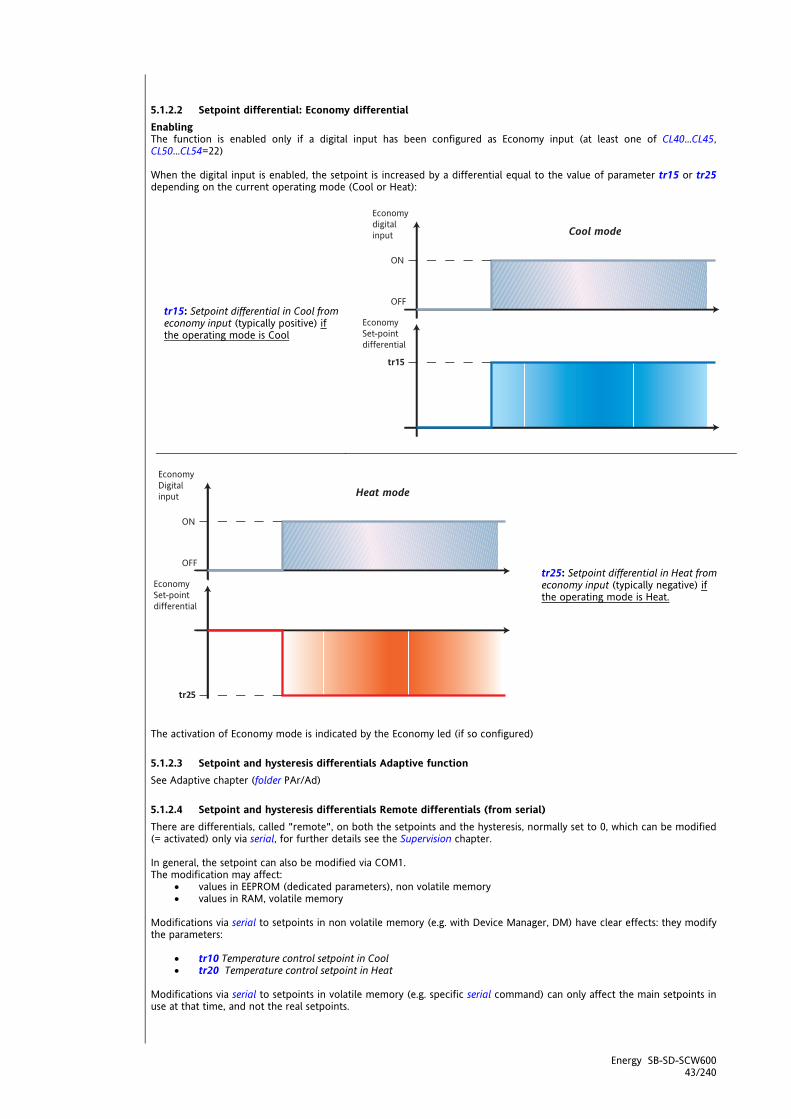
Energy SB-SD-SCW600 43/240
5.1.2.2 Setpoint differential: Economy differential Enabling The function is enabled only if a digital input has been configured as Economy input (at least one of CL40…CL45, CL50…CL54=22) When the digital input is enabled, the setpoint is increased by a differential equal to the value of parameter tr15 or tr25 depending on the current operating mode (Cool or Heat):
tr15: Setpoint differential in Cool from economy input (typically positive) if the operating mode is Cool
tr25: Setpoint differential in Heat from economy input (typically negative) if the operating mode is Heat.
The activation of Economy mode is indicated by the Economy led (if so configured)
5.1.2.3 Setpoint and hysteresis differentials Adaptive function See Adaptive chapter (folder PAr/Ad)
5.1.2.4 Setpoint and hysteresis differentials Remote differentials (from serial) There are differentials, called "remote", on both the setpoints and the hysteresis, normally set to 0, which can be modified (= activated) only via serial, for further details see the Supervision chapter. In general, the setpoint can also be modified via COM1. The modification may affect:
values in EEPROM (dedicated parameters), non volatile memory values in RAM, volatile memory
Modifications via serial to setpoints in non volatile memory (e.g. with Device Manager, DM) have clear effects: they modify the parameters:
tr10 Temperature control setpoint in Cool tr20 Temperature control setpoint in Heat
Modifications via serial to setpoints in volatile memory (e.g. specific serial command) can only affect the main setpoints in use at that time, and not the real setpoints.
<IMG INFO>
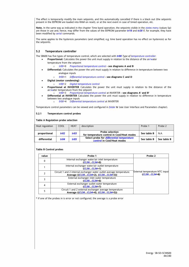
Energy SB-SD-SCW600 44/240
The effect is temporarily modify the main setpoints, and this automatically cancelled if there is a black out (the setpoints present in the EEPROM are loaded into RAM on reset), or at the next event in case of timed operation, etc. Note. In the same way as indicated in the chapter Time band operation, the setpoints visible in the states menu (values Sp) are those in use and, hence, may differ from the values of the EEPROM parameter tr10 and tr20 if, for example, they have been modified by serial commands. The same applies to the hysteresis parameters (and simplified, e.g. time band operation has no effect on hysteresis) as for the setpoints.
5.2 Temperature controller The SB600 has five types of temperature control, which are selected with tr00 Type of temperature controller:
Proportional: Calculates the power the unit must supply in relation to the distance of the air/water temperature from the setpoint
o tr00=0 Proportional temperature control - see diagrams A and B Differential: Calculates the power the unit must supply in relation to difference in temperature between two
analogue inputs o tr00=1 Differential temperature control - see diagrams C and D
Digital (motor condensing) o tr00=2 Digital temperature control
Proportional at INVERTER Calculates the power the unit must supply in relation to the distance of the air/water temperature from the setpoint
o tr00=3 Proportional temperature control at INVERTER - see diagrams A’ and B’ Differential at INVERTER Calculates the power the unit must supply in relation to difference in temperature
between two analogue inputs o tr00=4 Differential temperature control at INVERTER
Temperature control parameters can be viewed and configured in folder tr (see User Interface and Parameters chapter).
5.2.1 Temperature control probes Table A Regulation probe selection Heat regulation
COOL HEAT description Probe 1 Probe 2
proportional tr02 tr03 Probe selection for temperature control in Cool/Heat modes See table B N.A.
differential tr04 tr05 Select probe for differential temperature control in Cool/Heat modes See table B See table B
Table B Control probes
value Probe 1 Probe 2
0 Internal exchanger water/air inlet temperature (CL30…CL34=0)
1 Internal exchanger water/air outlet temperature (CL30…CL34=1)
2 Circuit 1 and 2 internal exchanger water outlet average temperature Average ((CL30…CL34=2), (CL30…CL34=3))
3 External exchanger inlet water temperature (CL30…CL34=6)
4 External exchanger outlet water temperature (CL30…CL34=7)
External temperature NTC input (CL30…CL34=8)
5 Circuit 1 and 2 external exchanger average temperature Average ((CL30…CL34=4), (CL30…CL34=5))
* if one of the probes in is error or not configured, the average is a probe error

Energy SB-SD-SCW600 45/240
5.2.2 Proportional temperature control This is a type of control which activates the power steps as a function of the divergence of the actual temperature from the real setpoint. Homogeneous or power stage compressors The steps (heat or cool) are discrete and there are a limited number of them (max 4 for SB devices). The number of steps (resources) requested is linked to the difference between the control temperature and the real setpoint; the greater the difference, the larger the number of steps (resources) used to achieve the setpoint. The temperature interval between application of one power step and the next depends on the proportional band and the number of resources available (see Compressors chapter). Temperature control is usually dependent on the inlet/outlet water/air temperature of the internal exchanger. Installations with double internal exchanger can control the temperature as a function of the average of the two temperatures measured at the exchanger outlets. In some applications (e.g. machines with water reversal in Heat mode) it may be necessary to use the external (recovery) exchanger inlet/outlet water temperature for temperature control. Various temperature control probes can be selected for Heat and Cool modes using the parameters given in Table B Control probes
5.2.3 Proportional power step temperature control in Cool/Heat mode Temperature control is enabled in Heat mode only if Enable heat pump tr01 = 1 Case tr00=0
Diagram A Diagram B COOL HEAT
Parameter Description
COOL HEAT Description tr02 tr03 Select temperature control probe in Cool / Heat tr14 tr24 Steps/compressors insertion differential in Cool / Heat
Setpoint Real setpoint in Cool / Heat Hysteresis Real control hysteresis in Cool / Heat
Note: The real hysteresis may not be greater than the differential. In this case the hysteresis is considered equal to the differential.
IMG INFO
IMG INFO

Energy SB-SD-SCW600 46/240
5.2.4 Temperature control at INVERTER in Cool / Heat mode The temperature controller in Cool / Heat mode is enabled only if the parameter Enable heat pump tr01 = 1 Case tr00=3
Diagram A’ Diagram B’ COOL HEAT
Aln Temp Temperature read by the probe selected for
temperature control in Cool (parameter tr02 - Select probe for temperature control in Cool) Or for differential temperature control in Cool (parameter tr04 - Select probe for temperature control in Cool)
Aln Temp Temperature read by the probe selected for temperature control in Cool (parameter tr03 - Select probe for temperature control in Heat) Or for differential temperature control in Cool (parameter tr05 - Select probe for temperature control in Heat)
Par. Description
COLD HEAT
tr14 tr24 Steps/compressors insertion differential in Cool / Heat
tr30 tr40 Temperature controller hysteresis with inverter in Cool / Heat
tr31 tr41 Temperature controller band with inverter in Cool / Heat
Speed tr32 tr42 Minimum speed with inverter in Cool / Heat
Speed tr33 tr43 Maximum speed with inverter in Cool / Heat
tr34 tr44 Inverter/compressors insertion differential in Cool / Heat Note: The real hysteresis may not be greater than the differential. In this case the hysteresis is considered equal to the differential. Cool Case Note: the sum tr30+tr31 must be less than tr34 Heat Case Note: the sum tr40+tr41 must be less than tr44 If this is not the case, the hysteresis + band value is considered equal to the differential.
HYSTERESISCOOLACTUAL
tr14 tr34
tr31tr30
Speed
Temp AIn
tr32 Min speed
tr33 Max speed
Step 1
Step 2
Step 3(stage 1)
Step 4(stage 2)
OFF
COOL setpoint<IMG INFO>
tr44 tr24 HYSTERESIS HEAT ACTUAL
tr40tr41
Speed
Temp AIn
tr32 Min Speed
tr33 Max Speed
Step 1
Step 2
Step 3(stage 1)
Step 4(stage 2)
OFF
HEAT setpoint
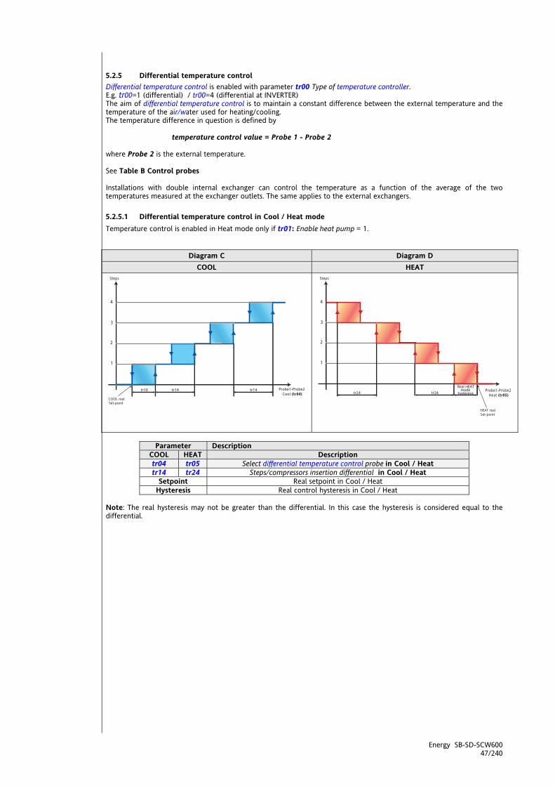
Energy SB-SD-SCW600 47/240
<IMG INFO>
5.2.5 Differential temperature control Differential temperature control is enabled with parameter tr00 Type of temperature controller. E.g. tr00=1 (differential) / tr00=4 (differential at INVERTER) The aim of differential temperature control is to maintain a constant difference between the external temperature and the temperature of the air/water used for heating/cooling. The temperature difference in question is defined by
temperature control value = Probe 1 - Probe 2
where Probe 2 is the external temperature. See Table B Control probes Installations with double internal exchanger can control the temperature as a function of the average of the two temperatures measured at the exchanger outlets. The same applies to the external exchangers.
5.2.5.1 Differential temperature control in Cool / Heat mode Temperature control is enabled in Heat mode only if tr01: Enable heat pump = 1.
Diagram C Diagram D COOL HEAT
Parameter Description
COOL HEAT Description tr04 tr05 Select differential temperature control probe in Cool / Heat tr14 tr24 Steps/compressors insertion differential in Cool / Heat
Setpoint Real setpoint in Cool / Heat Hysteresis Real control hysteresis in Cool / Heat
Note: The real hysteresis may not be greater than the differential. In this case the hysteresis is considered equal to the differential.
<IMG INFO>
220,5 161,15
0

Energy SB-SD-SCW600 48/240
5.2.6 Digital temperature control This function is active if parameter tr00: Type of temperature controller = 2. In the case of digital temperature control, the power step request depends on the state of specific digital inputs, typically driven by external thermostats, rather than analogue variables. The operating mode can also be selected via a digital input. Note: Safety timings, settings (compressor ON delay, pump ON, ..) and alarms are active as usual. The digital input configuration depends on the type of thermostat used in the application. We list below the meanings which can be associated with the digital inputs in question. Type 1 thermostat
Value DIL1÷DIL5 / AIL1÷AIL5 Description ±8 Digital input heat step 1 request ±9 Digital input heat step 2 request ±10 Digital input heat step 3 request ±11 Digital input heat step 4 request ±12 Digital input cool step 1 request ±13 Digital input cool step 2 request ±14 Digital input cool step 3 request ±15 Digital input cool step 4 request
Type 2 thermostat
Value DIL1÷DIL5 / AIL1÷AIL5 Description ±3 Remote Summer/Winter ±4 Power step 1 request ±5 Power step 2 request ±6 Power step 3 request ±7 Power step 4 request
For further details, see System Configuration (folder PAr/CL-Cr-CF) / paragraph Configuration of digital inputs (DIL1÷DIL5 and AIL1÷AIL5) / Table B - Digital inputs: configuration table Notes: - If two digital inputs are configured as heat step request and cool step request, activating both at the same time generates a configuration error; for further details see the alarms table; - If a digital input has been configured as heat request and the digital input for summer/winter is in the summer position, this generates a configuration error; - Temperature control depends directly on the activation of digital inputs which thus must be activated in a logical sequence. For example, power steps must be activated and deactivated in the fixed sequence 1-2-3-4 and 4-3-2-1.

Energy SB-SD-SCW600 49/240
6 OPERATING STATES (FOLDER PAR/ST) Once it has been configured, the Energy SBW600 is ready to control the utilities as a function of the temperature and pressure measured by the probes and the temperature control functions defined via its parameters. Operating mode parameters can be viewed and configured in folder St (see User Interface and Parameters sections) When Energy SBW600 is not OFF or on StdBy, it is in heat or cool mode Three operating states can be set in parameter St00- Select operating modes:
St00=0 Cool only COOL St00=1 Heat only HEAT St00=2 Heat and cool HEAT + COOL
Operating modes can be selected:
from the keyboard - if keys are enabled in parameters: o UI 21 - Enable MODE function from key Enables/disables mode selection from a key o UI 23 - Enable ON/OFF function from key Enables/disables ON/OFF key for switching the device on
or off from appropriately configured digital inputs:
o i.e. Remote ON/OFF o Remote STD-BY
St00 0 1 2 COOL HEAT HEAT+COOL
Cooling x NA x Heating NA x x
Standby (Stdby) x x x Remote Standby (Stdby) x x x
OFF x x x Remote OFF x x x
AS (see section on Sanitary Water) NA X
X
Operating mode
Remote AS (see section on Sanitary Water) NA X X
If different states are requested at the same time, the following priorities are assigned (in decreasing order):
Current operating State (current mode) Operating state after request
priority COOL HEAT HEAT+COOL
1 Digital input
configured as ON/OFF (§)
Digital input configured as ON/OFF (§)
Digital input configured as ON/OFF (§) Remote OFF (§)
2 ON/OFF key enabled
(press and hold DOWN key)
ON/OFF key enabled
(press and hold DOWN key)
ON/OFF key enabled (press and hold DOWN
key) OFF
3 Digital input configured as Standby
Digital input configured as
Standby
Digital input configured as Standby Standby
4 Mode key enabled (press and hold ESC
key)
Mode key enabled (press and hold ESC
key) NA
Mode selected by user
(see mode key, mode changeover function)
4 NA NA Mode key enabled (*)
Standby (*)
5 NA NA Select mode (**) (**)
action
6 NA NA Mode key enabled (press and hold ESC
key)
Mode selected by user
(see mode key, mode changeover function)
(§) In this case the key [local ON/OFF] has no effect on the operating mode (*) it will not be possible to switch from COOL mode to HEAT mode (HEAT label not visible by pressing and holding ESC key (Mode, change mode function)) (**) it will not be possible to switch from HEAT mode to COOL mode (COOL label not visible by pressing and holding ESC key (Mode, change mode function))
Operating states
Operating modes

Energy SB-SD-SCW600 50/240
6.1 Automatic changeover The automatic changeover function is enabled by parameter St01- Enable changeover from analogue input The Cool/Heat modes are selected by means of two different differentials set by parameter (St03 - Differential for automatic mode change in Heat for Heat mode, and St04 - Differential for automatic mode change in Cool for Cool mode); in the neutral zone (between the two setpoints), the mode can be set from a key as well (if enabled). See the graph below for more details;
6.1.1 Example of automatic changeover based on water temperature
6.1.2 Example of automatic changeover based on external air temperature
MODE Operating mode T H2O Water temperature (*) Ext Temp External temperature (*) SET COOL Real temperature control setpoint in Cool (**) SET HEAT Real temperature control setpoint in Heat (**) St03 Differential for automatic mode change in Heat St04 Differential for automatic mode change in Cool
(*) If St01= 1 see parameters St02 (**) The real setpoints may differ from the values of parameters tr10 and tr20 - see Operating modes - Temperature control (folder PAr/tr) Note: St04 is added to COOL setpoint; St03 is added to HEAT setpoint. Note: St03+St04 < HEAT setpoint - COOL setpoint, or the sum of differentials must never be more than HEAT setpoint - COOL setpoint
COOL
HEAT
ON
St04 St03
Set COOL Set HEAT
Ext Temp.
MODE
COOL
HEAT
ON
St04 St03
Set COOL Set HEAT
T H20
MODE
IMG INFO

Energy SB-SD-SCW600 51/240
6.2 Operating states table Operating states and associated functions/algorithms enabled/disabled for each one are listed in the table below. Function enabled Example: The Hot Start function can be enabled ONLY in HEAT mode
Function Cooling COOL
Heating HEAT
Std-By and remote Std-By
OFF and remote OFF
User interface (°)
Temperature controller
Select operating mode
Compressor
Internal circuit water pump
Recirculation fan
External exchanger fan
External circuit water pump
Internal circuit heaters
External circuit heaters
Auxiliary output
Boiler
Defrost
Dynamic setpoint
Economy
Adaptive function
Antifreeze with heat pump
Hot Start
Power limitation
Record running time
Manual alarm reset
Manual defrost
MFK
Alarms log
Diagnostics
Serial communication
(°) In this case the key [local ON/OFF] has no effect on the operating mode

Energy SB-SD-SCW600 52/240
6.3 Reversal valve management SB600 allows you to set the valve switching modes (slow/fast switching) based on the type of system by configuring parameter St05 - Reversal valve switching delay If the switching time St05 is different from zero, the inversion of the valve happens only with compressors switched off (“soft inversion”). The compressors are switched off and on according to set rules and times. It is a prudent mode, but one which ensures the required efficiency and speed.
6.3.1 Mode Change The operation is described below – diagrams A…D. Operation in defrost or in antifreeze with heat pump is described in the related chapters. Note that the mode change with St05=0 also occurs with compressors on and the operation is also identical in
defrost and antifreeze with heat pump
Diagram Parameter Mode Change A COOL - HEAT B
St05 different from 0 HEAT - COOL
C COOL - HEAT D St05 = 0 HEAT - COOL
Diagram A
Diagram B
Parameter Description St05 different from 0 Reversal valve switching delay CP20 Minimum off/on for same compressor CP23 Minimum on/on time for same compressor CP24 Minimum off/off time for different compressors
OFF
ON
time
OFF
ON Reversing valve
Compressor 2
Compressor 1 Compressor 1OFF
ON
CP24 CP23
CP20
Compressor 2
St05 St05
<IMG INFO> 339,95 121,9 0 2 113,2 0 -1
OFF
ON
OFF
ON Reversing valve
Compressor 2
Compressor 1 Compressor 1OFF
ON
CP24 CP23
CP20
Compressor 2
St05 St05
time <IMG INFO> 339,8 117,35 0 2 -2,75 2,4 -1

Energy SB-SD-SCW600 53/240
Diagram C
Diagram D
Parameter Description St05 = 0 Reversal valve switching delay
OFF
ON
time
OFF
ONReversing valve
Compressor 2
Compressor 1OFF
ON
<IMG INFO> 339,95 120,95 0 2 65,25 0 -1
OFF
ON
time
OFF
ON Reversing Valve
Compressor 2
Compressor 1OFF
ON
<IMG INFO> 339,95 119,05 0 2 42,35 0 -1

Energy SB-SD-SCW600 54/240
7 COMPRESSORS (FOLDER PAR/CP) Compressor parameters can be viewed and configured in folder CP (see User Interface and Parameters chapters). The parameters are:
CP00, CP01 to define the type and number of compressors in the installation; CP03..CP10 to set timings.
The Energy SBW600 is able to control “Alternate”, “Scroll” and “Screw” compressors in a range of configurations. The Energy SBW600 controls up to two cooling circuits, with one or two evaporators. The Energy SBW600 can control from one to four power steps, at most two per cooling circuit. The Energy SBW600 is also able to pilot the inverters for compressors by means of the following analogue outputs
Analogue stage 1 for Compressor Analogue stage 2 for Compressor
The type of compressor control depends on the configuration of the analogue outputs; The Energy SBW600 has 3 analogue outputs, 2 with voltage output 0-10V and one with current output 0-20mA or 4-20mA. Of these only a maximum of 2 can be configured as analogue outputs for compressor inverter control; depending on the number of outputs configured, only the first or both analogue stages are available (equivalent of step). NOTE: compressor management with converter is only suitable for systems with non-staged compressors. Safety timings can be set for the actuation of compressors and power stages to prevent damage. Special on/off sequences can be programmed to optimise the use of the available compressors and power. General conditions of operation In Off the compressors are switched off immediately and always (even when the safeties are active). In Stand-by the compressors are normally switched off; during the transition from On to Stand-by, they are switched off in accordance with their timings. In Stand-by, the compressors are activated in anti-freeze with heat pump mode. In On, further to the principal regulation specified in the following paragraphs, the following situations (with priority over the principal regulation itself) may occur: the compressors are switched off immediately in case of compressor shut-down alarms (see alarms table)
7.1 Types of compressor Compressors may be controlled in a variety of ways according to their number, size and construction. Parameter CP00 indicates the type of compressor:
Value CP00 Description 0 Non-power stage compressors 1 Alternate power stage compressors 2 Screw power stage compressors
Configuring digital outputs as compressor: The compressor or compressors, or compressor and its power stage is/are connected to one of the available relay outputs D01…D04, D06 or to the D05 open collector output, by setting the following parameters:
CL90…CL95= ±1…±4 for compressor1..4 CL90…CL95= ±50…±53 for power steps 1…4
7.1.1 Non-power stage compressors (CP00 = 0) This is the most simple case, the individual compressor is switched on/off via a single digital output. If more compressors are present, they can be of the same or a different power rating and switched on according to the power requirements of the installation. Compressor without power stage: CP00 = 0. Note: Set CP03 = 0
Power Compressor 0 Off 100% On
4 Homogeneous compressors without power stage: CP00 = 0
Power Compressor 1 Compressor 2 Compressor 3 Compressor 4 0 Off Off Off Off
25% On Off Off Off 50% On On* Off Off 75% On On* On* Off 100% On On* On* On*
*In this case, the switching on sequence is fixed. This may not always be the case.

Energy SB-SD-SCW600 55/240
Systems with inverters: since only two analogue outputs are available for compressor piloting, if the system has a greater number of compressors, management will be mixed between analogue and relays; in these cases the analogue steps are always the "highest" steps or those which are most distant from the setpoint. Refer to the paragraph Compressor Configuration / Permitted configurations in the case of non-staged compressors (CP00 = 0) forthe various combinations and configurations permitted based on the type of system, understood as the number of compressors and the number of circuits
7.1.2 Power stage compressors (CP00 = 1,2) The construction of these compressors enable them to modulate their power delivery by means of power stage activation. Each compressor is switched on or off by a single digital output, but other digital outputs control its power stage depending on the power requirements of the installation. The compressor is always switched on or off without power stage. There are two ways in which the power stage is activated: for alternate multi-cylinder compressors, for screw compressors. In the first case, the power stage is obtained by short circuiting the suction and discharge valves of the cylinders, in screw compressors by deviating the discharge flow to various positions along the screw. The actuation logic for the power stage relays is different in each case, see the following table: Alternate power stage compressors with 3 power stages: CP00 = 1 There are 3 power stages, i.e. the compressor can supply 0%, 25%, 50%, 75% or 100% of its power
Power Compressor Power stage 1 Power stage 2 Power stage 3 0 Off Off Off Off
25% On On On On 50% On On On Off 75% On On Off Off 100% On Off Off Off
Note: The compressor control timings are different from those of the power stages. See Compressor timings for more details. Note: note that, with CP00 = 2, the compressor starts (at 25% power) when two relays are actuated at the same time.
7.2 Compressor configuration the SBW600 can control from one to a maximum of four steps on a single circuit, or up to two steps per circuit for a total of two circuits. The installation is configured with the parameters:
CP01 - Number of circuits CP02 - Number of compressors per circuit CP03 - Number of power stages per compressor.
Multicompressor configurations always use compressors of the same type/construction. Multicircuit installations always employ symmetrical circuits. Permitted configurations:
In the case of non-power stage compressors (CP00 = 0)
Non-power stage compressors CP00 = 0 (set CP03=0) CP02 = 1 CP02 = 2 CP02 = 3 CP02 = 4
CP01 = 1 Compressor 1(§) Compressor 1 (*) Compressor 2 (**) (§)
Compressor 1 Compressor 2 Compressor 3
Compressor 1 Compressor 2 Compressor 3 Compressor 4
Compressor 1(*) Compressor 1 Compressor 2 Not allowed Ci
rcui
ts
CP01 = 2 Compressor 2(**) Compressor 1
Compressor 2
Not allowed
NOTE: Set CP03=0
(§) Step replaced by analogue stage 1 if only one analogue output is configured as compressor (*) Step replaced by analogue stage 1 if 2 analogue outputs are configured as compressor (**) Step replaced by analogue stage 2 if 2 analogue outputs are configured as compressor NOTE: asymmetrical or unbalanced distributions of inverter controls for compressors are not permitted

Energy SB-SD-SCW600 56/240
In the case of power stage compressors (CP00 = 1 and 2) with 1 power stage per compressor (CP03 = 1)
Compressors with 1 power stage CP00 = 1 and 2 CP03 = 1 CP02 = 1 CP02 = 2 CP02 = 3 CP02 = 4
CP01 = 1 Compr. 1, Step 0 Compr. 1, Step 1
Compr. 1, Step 0 Compr. 1, Step 1 Compr. 2, Step 0 Compr. 2, Step 1
Not allowed Not allowed
Compr. 1, Step 0 Compr. 1, Step 1 Ci
rcui
ts
CP01 = 2 Compr. 2, Step 0 Compr. 2, Step 1
Not allowed Not allowed Not allowed
LEGEND: (Compr. = compressor, Step = Step)
In the case of power stage compressors (Type of compressor CP00 = 1 and 2) with 2 power stages per
compressor (Number of power stages per compressor CP03 = 2)
Compressors with 2 power stages CP00 = 1 and 2 CP03 = 2 CP02 = 1 CP02 = 2 CP02 = 3 CP02 = 4
CP01 = 1 Compr. 1, Step 0
Compr. 1, Step 1 ( Compr. 1, Step 2
Not allowed Not allowed Not allowed
Circ
uits
CP01 = 2 Not allowed Not allowed Not allowed Not allowed
In the case of power stage compressors (CP00: Type of compressor = 1 and 2) with 3 power stages per compressor (CP03: Number of power stages per compressor 3 = )
Compressors with 3 power stages CP00 = 1 and 2 CP03 = 2 CP02 = 1 CP02 = 2 CP02 = 3 CP02 = 4
CP01 = 1
Compr. 1, Step 0 Compr. 1, Step 1 Compr. 1, Step 2 Compr. 1, Step 3
Not allowed Not allowed Not allowed
Circ
uits
CP01 = 2 Not allowed Not allowed Not allowed Not allowed
7.3 Compressor timing Compressor and power stage on/off states must be limited in time, to ensure the mechanical and electrical safety of the equipment. The SBW600 provides a set of safety parameters for compressors and power stages. In some cases these parameters are not relevant, as during defrosting, to ensure machine performance. In other cases, the safety timings may influence or modify the compressor operation logic.
CP20: Minimum time between switching off/on for a given compressor [Secx10] CP21: Minimum time between switching on/on for a given compressor [Secx10] CP22: Minimum on time for a compressor [Secx10] CP23: Minimum time between switching on/on for different compressors [Sec] CP24: Minimum time between switching off/off for different compressors [Sec] CP25: Minimum compressor on time for power stage increase [Sec] CP26: Minimum compressor on time for power stage decrease [Sec] CP27: Minimum time between switching on/off in defrost mode [Sec]
7.3.1 Minimum time between switching off/on for a given compressor Defined by parameter CP20: Minimum Off-On time for a given compressor . This is the minimum time that must elapse between one switch-off and the next start-up. This is expressed in seconds x 10 and is active even after a reset.
7.3.2 Minimum time between switching on/on for a given compressor Defined by parameter CP21: Minimum On-On time for a given compressor. This is the minimum time that must elapse between one start-up and the next. This is expressed in seconds x 10 and is active even after a reset.
7.3.3 Minimum compressor on time Parameter CP22: Minimum compressor on time defines the minimum time between a compressor switching on and off again. It is expressed in seconds x 10.
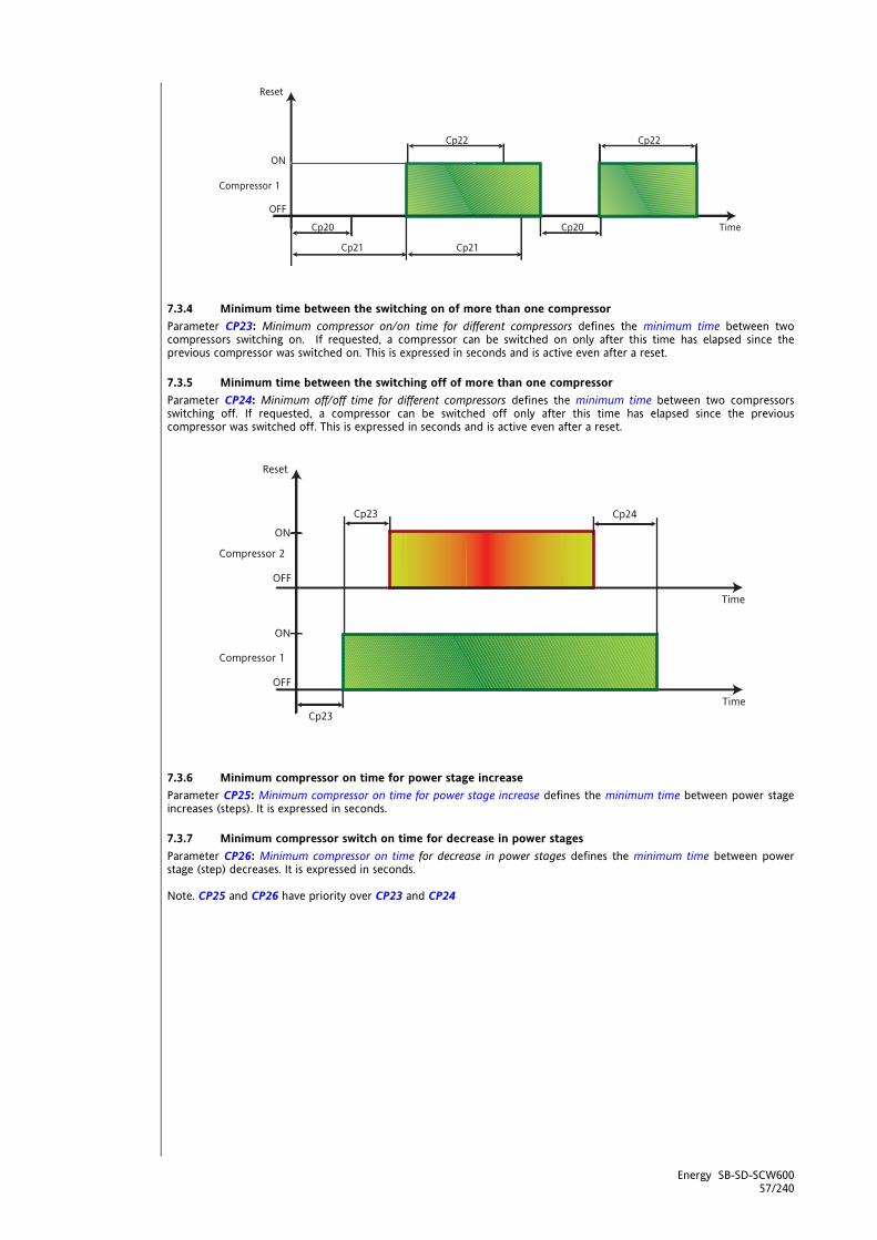
Energy SB-SD-SCW600 57/240
7.3.4 Minimum time between the switching on of more than one compressor Parameter CP23: Minimum compressor on/on time for different compressors defines the minimum time between two compressors switching on. If requested, a compressor can be switched on only after this time has elapsed since the previous compressor was switched on. This is expressed in seconds and is active even after a reset.
7.3.5 Minimum time between the switching off of more than one compressor Parameter CP24: Minimum off/off time for different compressors defines the minimum time between two compressors switching off. If requested, a compressor can be switched off only after this time has elapsed since the previous compressor was switched off. This is expressed in seconds and is active even after a reset.
7.3.6 Minimum compressor on time for power stage increase Parameter CP25: Minimum compressor on time for power stage increase defines the minimum time between power stage increases (steps). It is expressed in seconds.
7.3.7 Minimum compressor switch on time for decrease in power stages Parameter CP26: Minimum compressor on time for decrease in power stages defines the minimum time between power stage (step) decreases. It is expressed in seconds. Note. CP25 and CP26 have priority over CP23 and CP24
IMG INFO
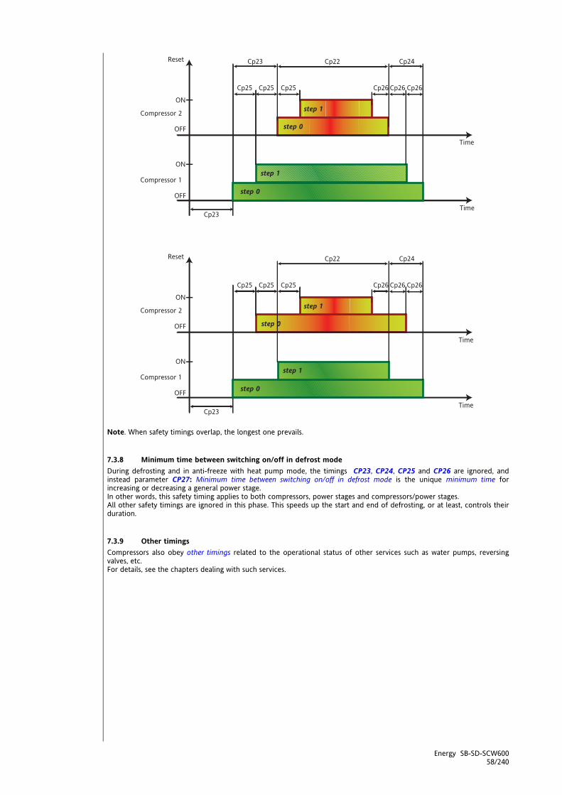
Energy SB-SD-SCW600 58/240
Note. When safety timings overlap, the longest one prevails.
7.3.8 Minimum time between switching on/off in defrost mode During defrosting and in anti-freeze with heat pump mode, the timings CP23, CP24, CP25 and CP26 are ignored, and instead parameter CP27: Minimum time between switching on/off in defrost mode is the unique minimum time for increasing or decreasing a general power stage. In other words, this safety timing applies to both compressors, power stages and compressors/power stages. All other safety timings are ignored in this phase. This speeds up the start and end of defrosting, or at least, controls their duration.
7.3.9 Other timings Compressors also obey other timings related to the operational status of other services such as water pumps, reversing valves, etc. For details, see the chapters dealing with such services.

Energy SB-SD-SCW600 59/240
7.4 Compressor on/off sequence
7.4.1 Availability of resources A resource is available if it can be used (switched on/off). A compressor ( or its power stage, if applicable) is available if • it is not blocked due to an alarm (see alarms section) • it is not blocked by safety timings (see compressors section) • it is not blocked by the configuration (see compressors section) • it is not blocked by regulation (e.g. block heat pump function, power limitation, etc.) In checking the availability of resources, the sequence Compressors Circuits is always followed. When selecting (actuating/deactivating) resources, one follows the opposite sequence: Circuits Compressors (selecting an evaporator selects its circuit). A circuit is said to be saturated when it is delivering all the power stages available from its compressors. A circuit is said to be active or on if it has at least one active compressor; it is off if none of its compressors is on. The current activation level of a particular circuit is defined as the total number of power steps that the compressors are supplying at the time (for example, a circuit that has 2 compressors with 1 power stage can supply up to 4 activation levels/steps) A compressor is said to be saturated when it is supplying its maximum number of deliverable steps (for example, a compressor with 3 power stages can supply at most 4 levels/steps of activation). A compressor is said to be active or on if it has at least one active step. The current activation level of a particular compressor is defined as the total number of power steps that it is supplying at the time (for example, a compressor that has 2 power stages can supply up to 3 activation levels/steps)
7.4.2 Managing resources If the number of active steps satisfies the current request, it is not modified. If the temperature controller requests to activate/deactivate a step, the availability of the compressors and circuits is first analysed to control the services on the basis of two logics, that of saturation and that of balancing. The procedure is to first select the best circuit and then the best compressor in that circuit. Saturation: The saturation policy attempts to distribute resources equally over the smallest possible number of
services compatible with the constraints imposed by other requirements, for example compressor safety timings. The resulting allocation is intended to have the largest possible number of compressors switched of and circuits deactivated at any one time.
Balancing: The balancing policy attempts to distribute resources equally over the largest possible number of
services compatible with the constraints imposed by other requirements, for example compressor safety timings. The resulting allocation is intended to have compressor and circuit output levels equalized as much as possible (in other words, the smallest number of compressors and circuits off).
There are two parameters which establish circuit (and evaporator) activation as well as activation of the compressors for each circuit:
CP10: Circuit balancing enable CP11: Compressor balancing enable
Value CP10 CP11
Description CP10 Description CP11
0 Saturation (circuits) Saturation (compressors) 1 Balancing (circuits) Balancing (compressors)

Energy SB-SD-SCW600 60/240
7.4.3 Resource selection criterion When the two control selections are applied (saturation and balancing), it may happen that one has to choose between resources which are equally available (for example, when switching on the very first service of all). This selection must therefore also take into account factors like hours of operation and fixed on/off sequences. the hours of operation of a circuit is the sum of the hours of operation of its compressors. Hours of operation: One chooses the circuit or compressor which has the least hours of operation when
switching on, and most hours of operation when switching off. This tends to use all resources equally.
Fixed sequence: On(1-2-3-4), Off(4-3-2-1)
In this case, the selection of the circuit or compressor follows a fixed sequence (given availability). This option uses the resources in a fixed manner, which can be useful in case of steps of different power or when managing secondary backup resources in special circumstances.
Fixed sequence INVERTER compressor: On(1-2-3-4), Off(4-3-2-1)
Only usable option in the case of single-circuit configuration with at least one compressor managed by INVERTER
Operating time: This option applies on when there is a single circuit with two compressors (non-power
stage) or two circuits with two compressors each, and uses the compressor resources (in this case, non-homogeneous) in a manner equalised to the load. If the effective operating time of the circuit (TE, time between switching the first compressor on and the last compressor off during the previous cycle) is less than the time set in the parameter, on the next request from the temperature controller (for that circuit) the first resource to be activated shall be that with the lowest index (“resource 1”) and then resource 2; if the effective operating time of the circuit is greater than the time set in the parameter, on the next request from the temperature controller the first resource to be activated shall be that with the highest index (“resource 2”) and then resource 1;
There are two parameters which establish circuit and activation as well as activation of the compressors for each circuit:
CP12: Circuit selection criterion CP13: Compressor selection criterion
Value Description CP12 Description CP13
0 Hours balancing Hours balancing 1 Sequence On 1,2; Off 2, 1 Sequence On 1,2,3 and 4; Off 4,3,2
and 1 2 // Operating time
7.4.4 Selecting the circuit/evaporator Parameter CP10: Enable circuit balancing is only relevant if there are two circuits. If set to 0 (saturation) all the power steps of a given circuit are first activated, followed by those of the other circuit. If set to 1 (balancing), the power steps are activated in such a way that both circuits deliver the same power, or the difference is at most one step. The circuit is selected according to the value of CP12: Circuit selection criterion
CP12 Saturation CP10 = 0
Balancing CP10 = 1
Hours of operation CP12 = 0
When switching on, the circuit with least hours of operation is selected (with compressors available for switching on) up to saturation, after which the second circuit is activated. When switching off, teh circuit with least steps active is selected (with compressors available for switching off) or (if the same number of steps are active on each), that with the highest number of hours of operation.
When switching on, the procedure starts with a step of the circuit with least hours of operation (with compressors available for switching on), this is then balanced with a step from the other circuit and so on until both are saturated. When switching off, the opposite sequence is followed, giving priority to the circuit with most hours of operation (with compressors available for switching off).
Fixed sequence On(1,2) Off(2,1) CP12 =1
When switching on, the first circuit is used up to saturation, after which the second circuit is activated. When switching off, first all the second circuit and then the first circuit is switched off.
When switching on, the procedure starts with a step of the first circuit, this is then balanced with a step from the other circuit and so on until both are saturated. When switching off, the opposite sequence is used.

Energy SB-SD-SCW600 61/240
7.4.5 Selecting the compressor or power stage Parameter CP11: Enable compressor balancing is only relevant if there are 2 power stage compressors in the same circuit (which for the SBW600 remains single, since it cannot control a second one with the same characteristics). If set to 0 (saturation) all the power steps of one compressor are first activated, followed by those of the other compressor. If set to 1 (balancing), the power steps are activated in such a way that both compressors deliver the same power, or the difference is at most one step. The compressor is selected according to the value of CP13: Compressor selection criterion. Parameter CP14: Compressor operation time for on sequence is used if the operation time of the previous cycle is used as the selection criterion.
CP13 Saturation CP11 = 0
Balancing CP11 = 1
Hours of operation CP13 = 0
When switching on, the available compressor with the least hours of operation is selected until it is saturated, after which the other compressors are selected. When switching off, first the available compressor with least power stages active is selected, or (for an equal number of power stages active) the one with the greater hours of operation.
When switching on, the procedure starts with the first power stage of the compressor with least hours of operation, then the first stage of the next compressor until all compressors are operating, then the second stages, etc.. When switching off, the procedure switches off the power stages of the available compressors with the same logic, favouring those with the greater hours of operation.
Fixed sequence On(1,2,3,4) Off(4,3,2,1) CP13 = 1
When switching on, the first compressor is used up to saturation, after which the second compressor is activated, and so on. When switching off, the first to be selected is that with the highest index, until it is completely switched off, and so on.
When switching on, the procedure starts with the first power stage of the first compressor, then the first stage of the second compressor until all compressors are operating, then the second stages, etc.. When switching off, the stages are switched off with the same logic, starting from the one with the highest index.
Operating time CP13 = 2
CP11 is irrelevant inasmuch as selection by operating time is not required if there are two power stage compressors in the same circuit. If the effective operating time of the circuit is less than the time set in parameter CP14, on the next temperature controller request the sequences On(1,2) and Off(2,1) are used. In the case of two circuits with two compressors each, the sequences are On(3,4) and Off(4,3), independently for the two circuits. Whereas, if the operating time is greater than CP14 the next sequences will be On(2,1) and Off(1,2).

Energy SB-SD-SCW600 62/240
8 INTERNAL CIRCUIT PUMP (FOLDER PAR/PI) The SBW600 controls one or two hydraulic pumps on the internal exchanger water circuit. Control may be digital or analogue, and depends on a number of system variables such as temperature controller status, external exchanger fan speed and internal exchanger water temperature. For systems with two pumps, these are connected in parallel, and at most one is operational at a time. Internal circuit water pump parameters can be viewed and configured in folder PI (see User Interface and Parameters chapters). The following must be configured: Digital control
at least one digital output as internal circuit water pump 1, using the parameters CL90…CL97 / CL80-CL81 if digital / CL61…CL63 if digital = ±14.
**at least one digital output as internal circuit water pump 2, using the parameters CL90…CL97 / CL80-CL81 if digital / CL61…CL63 if digital = ±15.
Analogue control
at least one analogue output as modulating internal circuit water pump 1, using the parameters CL80-CL81 if analogue / CL61…CL63 if analogue = ±59.
**at least one analogue output as modulating internal circuit water pump 2, using the parameters CL80-CL81 if analogue / CL61…CL63 if analogue = ±60.
** in the case of two pumps The configurable outputs for digital pump control are relays, whereas in modulating operation they are the internal triac (for direct control) or the pulse outputs (for external triacs) and the analogue outputs.
8.1 Configuration of internal circuit water pump Enabling The controller is enabled by setting parameter (Pi00 -Select internal circuit water pump operating mode) not equal to 0. Control of the second pump is enabled only if parameter (Pi05 - Maximum internal circuit water pump changeover start time is not equal to 0. Table 1 Parameter Description value 0 1 2
I pump P100 Select internal circuit water pump operating mode Pump disabled
Continuous operation (Always ON)
on request (pump on when compressor on)
0 Not equal to 0
II pump PI05 Maximum internal circuit water pump changeover start time Pump disabled
after this time (in minutes) the active pump is switched off and replaced by the second pump if available.
Table 2
Par Description value
0 1 2
antifreeze heater PI10
Enable internal circuit water pump on
when antifreeze heaters active
Internal circuit water pump
disabled
Internal circuit water pump
enabled //
Boiler PI11 Enable internal circuit special water pump
No enabling
Enable pump when the boiler is
on
Enable modulating
pump on the basis of the difference between internal
exchanger water/air inlet temperature and Internal exchanger
water/air outlet temperature.
See configuration of analogue inputs
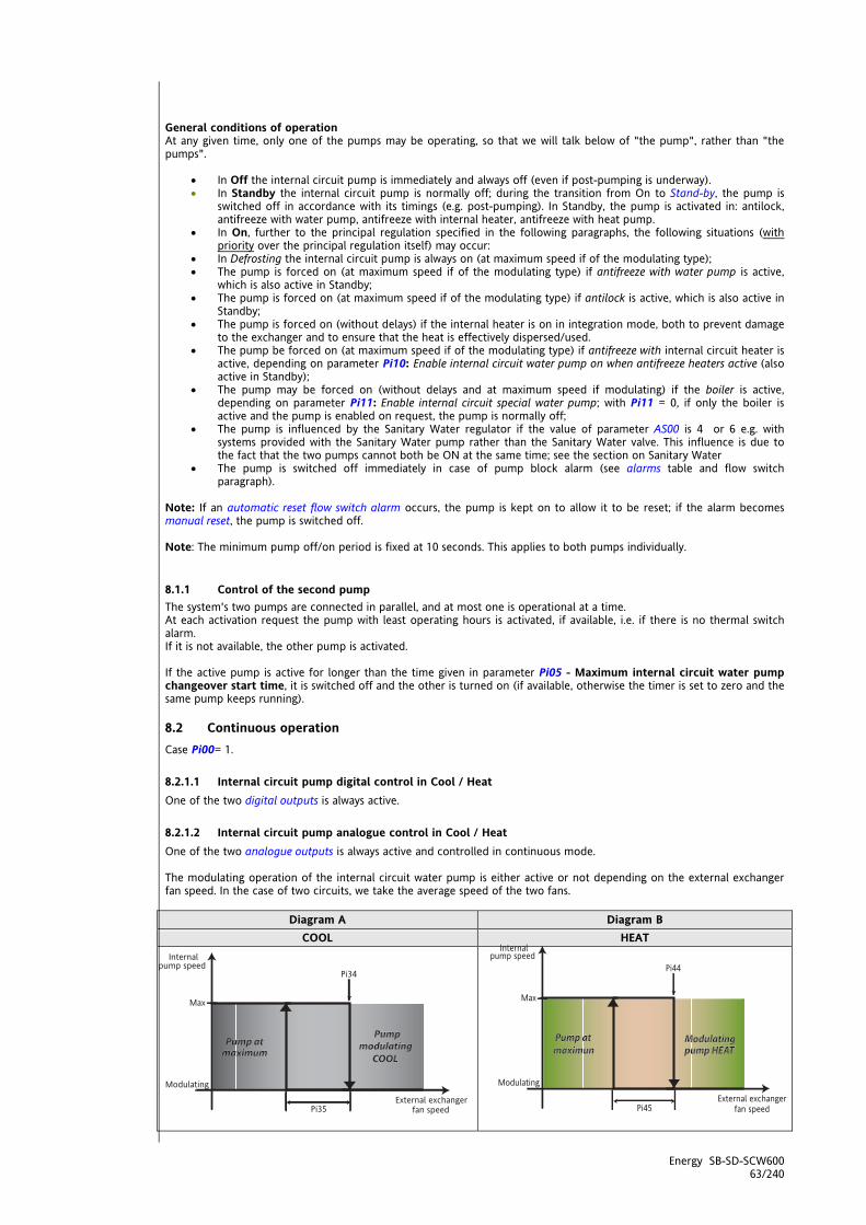
Energy SB-SD-SCW600 63/240
General conditions of operation At any given time, only one of the pumps may be operating, so that we will talk below of "the pump", rather than "the pumps".
In Off the internal circuit pump is immediately and always off (even if post-pumping is underway). In Standby the internal circuit pump is normally off; during the transition from On to Stand-by, the pump is
switched off in accordance with its timings (e.g. post-pumping). In Standby, the pump is activated in: antilock, antifreeze with water pump, antifreeze with internal heater, antifreeze with heat pump.
In On, further to the principal regulation specified in the following paragraphs, the following situations (with priority over the principal regulation itself) may occur:
In Defrosting the internal circuit pump is always on (at maximum speed if of the modulating type); The pump is forced on (at maximum speed if of the modulating type) if antifreeze with water pump is active,
which is also active in Standby; The pump is forced on (at maximum speed if of the modulating type) if antilock is active, which is also active in
Standby; The pump is forced on (without delays) if the internal heater is on in integration mode, both to prevent damage
to the exchanger and to ensure that the heat is effectively dispersed/used. The pump be forced on (at maximum speed if of the modulating type) if antifreeze with internal circuit heater is
active, depending on parameter Pi10: Enable internal circuit water pump on when antifreeze heaters active (also active in Standby);
The pump may be forced on (without delays and at maximum speed if modulating) if the boiler is active, depending on parameter Pi11: Enable internal circuit special water pump; with Pi11 = 0, if only the boiler is active and the pump is enabled on request, the pump is normally off;
The pump is influenced by the Sanitary Water regulator if the value of parameter AS00 is 4 or 6 e.g. with systems provided with the Sanitary Water pump rather than the Sanitary Water valve. This influence is due to the fact that the two pumps cannot both be ON at the same time; see the section on Sanitary Water
The pump is switched off immediately in case of pump block alarm (see alarms table and flow switch paragraph).
Note: If an automatic reset flow switch alarm occurs, the pump is kept on to allow it to be reset; if the alarm becomes manual reset, the pump is switched off. Note: The minimum pump off/on period is fixed at 10 seconds. This applies to both pumps individually.
8.1.1 Control of the second pump The system's two pumps are connected in parallel, and at most one is operational at a time. At each activation request the pump with least operating hours is activated, if available, i.e. if there is no thermal switch alarm. If it is not available, the other pump is activated. If the active pump is active for longer than the time given in parameter Pi05 - Maximum internal circuit water pump changeover start time, it is switched off and the other is turned on (if available, otherwise the timer is set to zero and the same pump keeps running).
8.2 Continuous operation Case Pi00= 1.
8.2.1.1 Internal circuit pump digital control in Cool / Heat One of the two digital outputs is always active.
8.2.1.2 Internal circuit pump analogue control in Cool / Heat One of the two analogue outputs is always active and controlled in continuous mode. The modulating operation of the internal circuit water pump is either active or not depending on the external exchanger fan speed. In the case of two circuits, we take the average speed of the two fans.
Diagram A Diagram B COOL HEAT
<IMG INFO> 226,3 124,3 0 2

Energy SB-SD-SCW600 64/240
Parameter COOL HEAT Description
PI02 Internal circuit water pump pick-up time. PI30 PI40 Minimum speed internal circuit water pump in Cool / Heat PI31 PI41 Maximum speed internal circuit water pump in Cool / Heat PI34 PI44 Fan speed setpoint to modulate internal circuit water pump in Heat PI35 PI45 Fan speed hysteresis to modulate internal circuit water pump in Heat
Control sensor Internal exchanger water/air outlet temperature or the difference between
Internal exchanger water/air inlet temperature and Internal exchanger water/air outlet temperature
Modulating function in Cool / Heat mode The internal circuit modulating pumps connected to the analogue outputs are switched on at maximum speed (relative to the current mode of operation) for a period given in parameter Pi02 - Internal circuit water pump pick-up time. After this time, the pump is run at the speed requested by the controller.
Diagram C Diagram D COOL HEAT
Parameter COOL HEAT Description
PI02 Internal circuit water pump pick-up time. PI30 PI40 Minimum speed internal circuit water pump in Cool / Heat PI31 PI41 Maximum speed internal circuit water pump in Cool / Heat PI32 PI42 Minimum internal circuit water pump speed setpoint in Cool/Heat PI33 PI43 Internal circuit water pump proportional band in Cool / Heat
Control sensor Internal exchanger water/air outlet temperature or the difference between
Internal exchanger water/air inlet temperature and Internal exchanger water/air outlet temperature
Note The pump runs at minimum speed if the compressors are off. Note A probe must be configured as Internal exchanger water/air outlet temperature and if two probes are so configured, the average is taken. Note: If Pi00=2 e.g. if the difference between
Internal exchanger water/air inlet temperature and Internal exchanger water/air outlet temperature
is considered, it is not permitted to have two output probes.
8.3 Operation on call Case Pi00= 2.
8.3.1.1 Internal circuit pump digital control in Cool / Heat One of the two digital outputs is active in parallel with the compressor. The internal circuit pump is activated when the main temperature controller calls the first step. The compressor starts after the delay given in parameter Pi20: Delay internal circuit water pump on and compressor on (Pre-pumping). Once the last power stage of the compressor is off, the pump is switched off after the delay given in Pi21: Delay compressor off - internal circuit water pump off (Post-pumping).
<IMG INFO><IMG INFO>
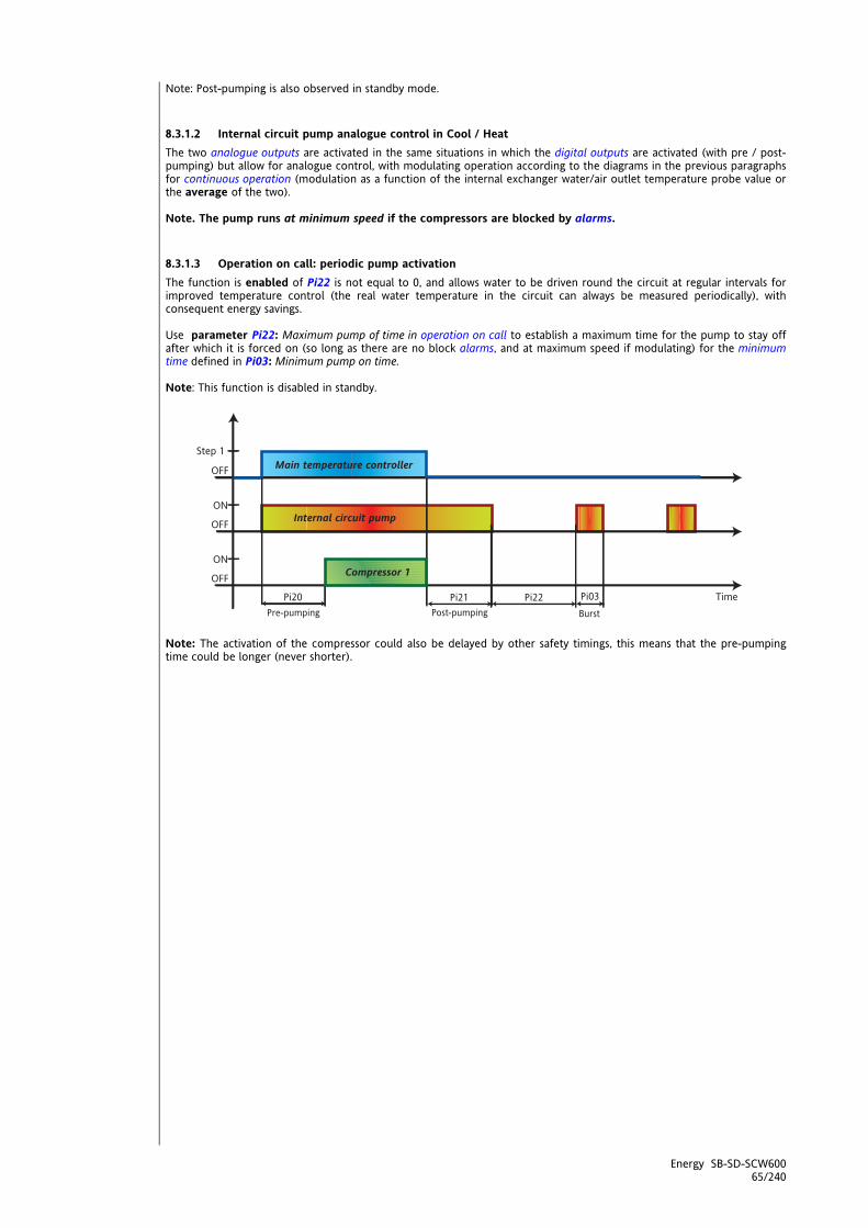
Energy SB-SD-SCW600 65/240
Note: Post-pumping is also observed in standby mode.
8.3.1.2 Internal circuit pump analogue control in Cool / Heat The two analogue outputs are activated in the same situations in which the digital outputs are activated (with pre / post-pumping) but allow for analogue control, with modulating operation according to the diagrams in the previous paragraphs for continuous operation (modulation as a function of the internal exchanger water/air outlet temperature probe value or the average of the two). Note. The pump runs at minimum speed if the compressors are blocked by alarms.
8.3.1.3 Operation on call: periodic pump activation The function is enabled of Pi22 is not equal to 0, and allows water to be driven round the circuit at regular intervals for improved temperature control (the real water temperature in the circuit can always be measured periodically), with consequent energy savings. Use parameter Pi22: Maximum pump of time in operation on call to establish a maximum time for the pump to stay off after which it is forced on (so long as there are no block alarms, and at maximum speed if modulating) for the minimum time defined in Pi03: Minimum pump on time. Note: This function is disabled in standby.
Note: The activation of the compressor could also be delayed by other safety timings, this means that the pre-pumping time could be longer (never shorter).

Energy SB-SD-SCW600 66/240
<IMG INFO> 51,85
8.4 Pump antilock mode This function prevents any mechanical faults due to extended disuse. The antilock function is active when:
enabled by parameter (PI01 - Internal circuit water pump idle time due to antilock > 0). See table 3 always active, except for OFF (local and remote) unless alarms switch off the pump
If the pump stays off for longer than or equal to Pi01: Internal circuit water pump idle time due to antilock, the controller forces it on (at maximum speed if modulating) for the time set in parameter Pi03: Minimum pump on time. Table 3
Antilock Parameter Description Value
0 >0
PI01 Internal circuit water pump idle time due to antilock Function disabled Function enabled
Diagram E PI03 Minimum internal circuit water pump start time Time in seconds x 10
Diagram E Pump antilock
Note: the broken line indicates the second pump, if present
<IMG INFO>

Energy SB-SD-SCW600 67/240
8.5 Antifreeze operation with pump The antifreeze function runs when: enabled by parameter Pi50 -Select probe for internal circuit + water pump antifreeze.
See table 4 always active, except for OFF (local and remote) and Stdby (local and remote) unless alarms switch off the
pump Table 4 - Pi50
Value Probe 0 No probe (pump in antifreeze disabled) 1 Internal exchanger water/air inlet temperature 2 Internal exchanger water/air outlet temperature 3 Internal exchanger water outlet temperature circuit 1 4 Internal exchanger water outlet temperature circuit 2 5 Circuit 1 and 2 internal exchanger water outlet minimum temperature 6 External temperature
Diagram F Antifreeze operation with pump
Parameter Description PI51 Internal circuit water pump regulator setpoint for antifreeze PI52 Internal circuit water pump regulator hysteresis for antifreeze
Control probe Pi50 Select probe for internal circuit + water pump antifreeze
Note. If the probe selected for antifreeze with the internal circuit pump is in error, the machine is blocked.
<IMG INFO>
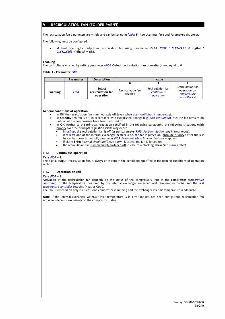
Energy SB-SD-SCW600 68/240
9 RECIRCULATION FAN (FOLDER PAR/FI) The recirculation fan parameters are visible and can be set up in folder FI (see User Interface and Parameters chapters). The following must be configured:
at least one digital output as recirculation fan using parameters CL90…CL97 / CL80-CL81 if digital / CL61…CL63 if digital = ±18.
Enabling The controller is enabled by setting parameter (Fi00 -Select recirculation fan operation) not equal to 0. Table 1 - Parameter Fi00
Parameter Description value 0 1 2
Enabling Fi00 Select
recirculation fan operation
Recirculation fan disabled
Recirculation fan continuous operation
Recirculation fan operation on temperature
controller call General conditions of operation
In Off the recirculation fan is immediately off (even when post-ventilation in underway). In Standby teh fan is off, in accordance with established timings (e.g. post-ventilation). ote: the fan remains on
until all of the compressors have been switched off In On, further to the principal regulation specified in the following paragraphs, the following situations (with
priority over the principal regulation itself) may occur: In defrost, the recirculation fan is off (as per parameter Fi03: Post-ventilation time in Heat mode); if at least one of the internal exchanger heaters is on, the fan is forced on (absolute priority); after the last
heater has been turned off, parameter Fi03: Post-ventilation time in Heat mode applies; if alarm Er30: Internal circuit antifreeze alarm, is active, the fan is forced on; the recirculation fan is immediately switched off in case of a blocking alarm (see alarms table)
9.1.1 Continuous operation Case Fi00 = 1. The digital output recirculation fan, is always on except in the conditions specified in the general conditions of operation section.
9.1.2 Operation on call Case Fi00 = 2. Activation of the recirculation fan depends on the status of the compressors (not of the compressor temperature controller), of the temperature measured by the internal exchanger water/air inlet temperature probe, and the real temperature controller setpoint (Heat or Cool). The fan is switched on only is at least one compressor is running and the exchanger inlet air temperature is adequate. Note. if the Internal exchanger water/air inlet temperature is in error (or has not been configured), recirculation fan activation depends exclusively on the compressor status.
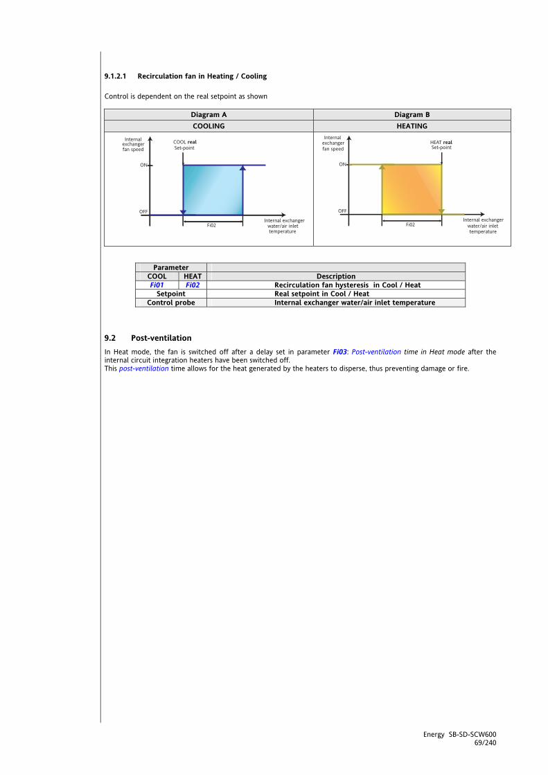
Energy SB-SD-SCW600 69/240
9.1.2.1 Recirculation fan in Heating / Cooling Control is dependent on the real setpoint as shown
Diagram A Diagram B COOLING HEATING
Parameter COOL HEAT Description Fi01 Fi02 Recirculation fan hysteresis in Cool / Heat
Setpoint Real setpoint in Cool / Heat Control probe Internal exchanger water/air inlet temperature
9.2 Post-ventilation In Heat mode, the fan is switched off after a delay set in parameter Fi03: Post-ventilation time in Heat mode after the internal circuit integration heaters have been switched off. This post-ventilation time allows for the heat generated by the heaters to disperse, thus preventing damage or fire.
<IMG INFO>

Energy SB-SD-SCW600 70/240
10 EXTERNAL EXCHANGER FAN (FOLDER PAR/FE) The SBW600 controls (via digital outputs) the ventilation of the air condensation units of the two chiller/heat pump temperature control circuits. Alternatively, it can control ventilation in a modulating mode, via analogue outputs . The configurable outputs for digital pump control are relays, whereas in modulating operation they are the internal triac (for direct control) or the pulse outputs and the analogue outputs (indirect control). External exchanger fan parameters can be viewed and configured in folder FE (see User Interface and Parameters chapters). The following must be configured:
at least one digital output as external exchanger fan with parameters CL90…CL97 / CL80-CL81 if digital / CL61…CL63 if digital = ±19 (circuit 1)/ ±20 (circuit 2).
Enabling The controller is enabled by setting parameter FE00 - External exchanger fan mode selection not equal to 0. Table 1 - Parameter FE00
Parameter Description Value 0 1 2
Enabling FE00 External exchanger fan mode selection
Ventilation disabled
Continuous operation (Always ON)
Operation on call (ON when compressor ON)
General conditions of operation
InOff the fans are switched off immediately and always (even when the cut-off bypass is active). In Standby the fans are normally switched off; during the transition from On to Standby, the fans are switched
off in accordance with their timings (e.g. bypass on current cut-off). If FE11=2 the fans are active at the same time as the external exchanger heaters in antifreeze mode.
In On, further to the principal regulation specified in the following paragraphs, the following situations (with priority over the principal regulation itself) may occur:
In Defrost the behaviour of the fans depends on parameter FE11: Enable special open system intercooler fan on (see below for details);
if the external exchanger heaters are on (or if at least one is on in the case of 2 heaters), the fans are activated if FE11=2 . In the case of two circuits, the fans of both circuits are activated; the external exchanger fans are switched off immediately in case of fan shut-down alarms (see alarms
table)
Parameter COOL HEAT Description FE30 FE50 Minimum speed external exchanger fan in Cool / Heat FE31 FE51 Average speed external exchanger fan in Cool / Heat FE32 FE52 Maximum speed external exchanger fan in Cool / Heat
Setpoint Real setpoint in Cool / Heat Control probe External exchanger water/air inlet temperature
External exchanger fan on pick-up The external circuit modulating pumps connected to the analogue outputs _AO_VenPerC1 and _AO_VenPerC2 are switched on at maximum speed (relative to the current mode of operation) for a period given in parameter FE01: External exchanger fan pick-up time. After this time, the pump is run at the speed requested by the controller. External exchanger fan control input Control is achieved with the value of the analogue input configured with parameters FE33: Select probe for external exchanger fan regulation in Cool and FE53: Select probe for external exchanger fan regulation in Heat. Parameters table FE33 and FE53
Value Description Regulation 0 No probe On or On/Off 1 External exchanger temperature (circuit 1 and 2) Direct 2 High pressure input (circuit 1 and 2) Direct 3 Low pressure input (circuit 1 and 2) Reversal 4 External exchanger pressure (circuit 1 and 2) Direct 5 Internal exchanger pressure (circuit 1 and 2) Reversal 6 Internal exchanger water/air inlet temperature Direct 7 Internal exchanger water/air outlet temperature Direct
If the plant has two circuits, the fans on the two external exchangers are controlled independently, on separate probes: both circuits must have analogue inputs configured for this purpose. If not, ventilation will always be active.

Energy SB-SD-SCW600 71/240
Analogue inputs for ventilation control
Description U.M. External exchanger temperature circuit 1 °C External exchanger temperature circuit 2 °C High pressure input circuit 1 Bar High pressure input circuit 2 Bar Low pressure input circuit 1 Bar Low pressure input circuit 2 Bar External exchanger pressure circuit 1 Bar External exchanger pressure circuit 2 Bar Internal exchanger pressure circuit 1 Bar Internal exchanger pressure circuit 2 Bar Internal exchanger water/air inlet temperature °C Internal exchanger water/air outlet temperature °C
10.1.1 Continuous operation Example FE00= 1. Ventilation is activated, independently of the state of the compressors on the basis of the value of the analogue input configured for control. The parameter FE21- External exchanger fan preventilation time must be set to 0. Note: If an analogue input is not configured or if the configured analogue input is in error, ventilation is always active (at maximum speed if modulating).
10.1.1.1 External exchanger fan digital control in Cool / Heat
Diagram A Diagram B COOLING HEATING
Analogue input control External exchanger
temperature High pressure input External exchanger
pressure
Low pressure input Internal exchanger pressure
External exchanger temperature Low pressure input
External exchanger pressure
High pressure input Internal exchanger pressure
Parameter COOL HEAT Description FE33 FE53 Select external exchanger fan control probe in Cool/Heat FE34 FE54 Minimum external exchanger fan speed setpoint in Cool / Heat FE38 FE58 External exchanger fan cut-off hysteresis in Cool / Heat FE39 FE59 External exchanger fan cut-off differential Control probe External exchanger water/air inlet temperature
<IMG INFO><IMG INFO>

Energy SB-SD-SCW600 72/240
10.1.1.2 External exchanger fan analogue control in Cool / Heat Analogue input control: External exchanger temperature High pressure input External exchanger pressure circuit
Analogue input control: Low pressure input Internal exchanger pressure
COOL
Analogue input control: External exchanger temperature Low pressure input External exchanger pressure circuit
Analogue input control: High pressure input Internal exchanger pressure
HEAT
Parameter COOL HEAT Description Control probe FE33 FE53 Select probe for external exchanger fan control in Cool/Heat
FE34 FE54 Minimum external exchanger fan speed setpoint in Cool / Heat FE35 FE55 Maximum external exchanger fan speed differential in Cool / Heat FE38 FE58 External exchanger fan cut-off hysteresis in Cool / Heat FE39 FE59 External exchanger fan cut-off differential Control probe Select external exchanger fan control probe in Cool/Heat
10.1.2 Operation on call Case FE00 = 2. Ventilation is activated, on the basis of the value of the analogue input configured for control and depending on the state of the compressors Note: If an analogue input is not configured or if the configured analogue input is in error, ventilation is activated exclusively on the basis of the state of the compressors (at maximum speed if modulating).
<IMG INFO>
<IMG INFO> 425,05 162,25 0 2

Energy SB-SD-SCW600 73/240
10.1.2.3 External exchanger fan digital control in Cool / Heat External exchanger fan control is activated at the moment in which the main temperature controller calls the first step of the temperature control circuit (to which the external exchanger belongs). The compressor starts after the delay given in parameter FE21: External exchanger fan preventilation time. Note: compressor activation may be delayed by other safety timings. Furthermore, the digital outputs are controlled by parameter FE34: External exchanger fan minimum speed setpoint in Cool as for continuous operation, with the following exception: after the compressor is activated (meaning the first compressor or power stage of the circuit in question), for the delay given in parameter FE20: Bypass time for external exchanger fan cut-off the fans are forced on even if the controller is requesting cut-off. Pre-ventilation is used in Cool to prevent high temperatures on the exchanger when the compressor is switched on. The cut-off bypass prevents extreme temperatures on the exchanger. Note: if there are alarms blocking the compressors, external exchanger fan control remains active even with the compressors off. Note: The activation of the compressor could also be delayed by other safety timings, this means that the pre-ventilation time could be longer (never shorter).
COOL
<IMG INFO>

Energy SB-SD-SCW600 74/240
HEAT
Note: if there are alarms blocking the compressors, external exchanger fan control remains active even with the compressors off.
10.1.2.4 External exchanger fan analogue control in Cool The analogue outputs are activated exactly as the respective digital outputs (with pre-ventilation and cut-off bypass) and are modulated, except for the cut-off bypass period (where the fans are activated at minimum speed if the controller requests cut-off), according to parameter FE34: External exchanger fan minimum speed setpoint in Cool as for continuous operation. If there is no request for steps the fan is normally off.
10.1.2.5 External exchanger fan analogue control in Heat The analogue outputs are activated exactly as the respective digital outputs (with cut-off bypass) and are modulated, except for the cut-off bypass period (where the fans are activated at minimum speed if the controller requests cut-off), according to parameter FE54: External exchanger fan minimum speed setpoint in Heat as for continuous operation. If there is no request for steps the fan is normally off.
<IMG INFO>

Energy SB-SD-SCW600 75/240
10.2 Fan control in defrost Fan activation in defrost mode is useful because pressure at the external exchanger can reach alarm levels if the exchanger is not totally de-iced. To prevent a high pressure alarm in this situation, the fans are run (at minimum speed if modulating). The behaviour of the external exchanger fan during defrost is determined by FE11: Enable special open system intercooler fan on, in which the fans run at maximum speed. If the machine has two temperature control circuits, the status of the fan is dependent on the defrost condition of its respective circuit. On completion of defrosting the fan resumes operation as requested by its controller.
If FE11 = 0, the fan is forced off throughout defrosting. If FE11 = 1, the fan is off or on at minimum speed (digital output active) depending on the analogue input
configured for control of the fan in defrost and parameter FE12: External exchanger fan on setpoint in defrost in the following way:
FE12: External exchanger fan on setpoint in defrost FE13: External exchanger fan on hysteresis in defrost FE14: Select probe for external exchanger fan regulation in defrost Parameter table FE14
Value FE14
Description
0 No probe 1 External exchanger temperature (circuit 1 and 2) 2 High pressure input (circuit 1 and 2) 3 External exchanger pressure (circuit 1 and 2)
Note: if there are two temperature control circuits, each must have a probe configured for this purpose. If no analogue input is configured or if the configured input is in error, ventilation is always at minimum during defrost (maximum in coil drainage). Note: At the end of defrost, the fans are switched on (at maximum speed if modulating) for the time set in parameter dF23: Coil drainage time, before the reversing valve switches.
10.3 Fan control with single condensation Parameter FE10: Enable single condensation configures 2 circuit machines with single condensation. if FE10 = 0 the two fans are independent and depend on the condensation pressure/temperature and the state of the compressors on the individual circuits. If FE10 = 1 the 2 (in reality 2 digital and 2 analogue) external exchanger fan outputs operate in parallel at the maximum output value of the two controllers for the two circuits.
<IMG INFO> 339,95 188,9

Energy SB-SD-SCW600 76/240
11 EXTERNAL CIRCUIT PUMP (FOLDER PAR/PE) External circuit water pump parameters can be viewed and configured in folder PE (see User Interface and Parameters chapters). At least one digital output must be configured as External Circuit Water Pump with parameters CL90…CL97 = ±16. See chapter System configuration (folder PAr/CL-Cr-CF) / Configuration of digital outputs Enabling The external circuit water pump can be enabled by parameter (PE00 - External circuit water pump mode selection=1)
Parameter Description value
0 1 2 3
PE00 External circuit water pump mode selection
Pump disabled
Continuous operation (Always ON)
NOT USED
Operation synchronised with external exchanger fans
Based on PE00 the external circuit pump can operate in continuous mode or synchronised with the external exchanger fans. General conditions of operation In Off the pump is always off. In Standby the pump is normally off; it is activated at the same time as the external exchanger heater in antifreeze ( if PE00=1). If PE00=3 the pump is activated only if the external exchanger fans are activated. In On the pump is always on if PE00 = 1. If PE00=3 the External Circuit Water Pump is activated “in parallel” to the external exchanger heaters: e.g. the pump is activated if the external exchanger fan is activated (single-circuit systems), or if at least one of the two fans is activated (dual-circuit systems). Notes: The pump is immediately switched off in the event of boiler lock alarm (see alarms table). If an automatic reset flow switch alarm occurs, the pump is kept on to allow it to be reset; if the alarm becomes manual reset, the pump is switched off. The minimum pump off/on period is fixed at 10 seconds.

Energy SB-SD-SCW600 77/240
12 INTERNAL EXCHANGER ELECTRIC HEATERS (FOLDER PAR/HI) The SB600 controls internal exchanger heaters 1 and 2, which act both for the antifreeze function (typically in machines with water-type internal exchanger) and integration for the heat pump/heating function (air and water). Parameters for internal circuit exchanger heaters can be viewed and configured in folder HI: Internal exchanger electric heater parameters (see User Interface and Parameters chapters). Antifreeze/integrated use heaters should be connected to a relay output (°) DO1..D04, D06 (see).
They are active only when the relative parameter enabling them HI00, HI02=1 (see table) (°) The heater control outputs are all and exclusively those outputs with ON/OFF control. The heaters can be used in a variety of ways depending on the type of system. We can have one or two internal exchangers and one or two circuits. In the case of a single exchanger with single/double circuit: in antifreeze, defrost and integration the heaters are controlled in equivalent mode. In the case of a double exchanger with double circuit: in antifreeze and defrost the two heaters are controlled differently, depending on the variables of the circuit in question; in integration they are controlled equivalently. For greatest configurability:
the number of antifreeze heaters and integration heaters can be set independently; the control analogue input can be determined individually. The heaters (1 or 2) can be used only for antifreeze, only for integration/heating, or for both functions at the
same time.
heaters Parameter Description value
0 1 Antifreeze (Standby) HI00 Enable internal exchanger heater regulator in
standby for antifreeze Heaters disabled Heaters enabled
See Heaters in defrost
paragraph HI01
Enable force heaters on during defrost
See parameters table Hi01
Antifreeze HI10 Select probe for antifreeze internal exchanger +
heater 1
Antifreeze HI11 Select probe for antifreeze internal exchanger +
heater 2
See Parameters table Hi10 and Hi11
integrated use HI20 Enable integrated use of internal exchanger heaters
See parameters table Hi20
12.1 Internal antifreeze heater Enabling The internal exchanger antifreeze heaters are enabled with parameters
HI10 - Select probe for antifreeze internal exchanger + heater 1 HI11 - Select probe for antifreeze internal exchanger + heater 2
General conditions of operation
In Off the internal exchanger antifreeze heaters are immediately and always off. In Standby the internal exchanger antifreeze heaters are active if so configured with ( Hi00 -Enable internal
exchanger antifreeze heaters in Stand-By). In On, further to the principal regulation specified in the following paragraphs, the following situations (with
priority over the principal regulation itself) may occur: In Defrost the internal circuit heaters are controlled by parameter Hi01: Enable force heaters on during
defrost. See dedicated paragraph The internal circuit heaters are immediately turned off during heater block alarms (see alarms table).
Note: There are no safety times for heater on/off.

Energy SB-SD-SCW600 78/240
12.1.1 Internal circuit antifreeze heater control
Parameter Parameter
Hi10 Select probe for antifreeze internal exchanger + heater 1 Control probe Hi11 Select probe for antifreeze internal exchanger + heater 2
Hi12 Internal exchanger heater regulator setpoint for antifreeze Hi13 Maximum internal exchanger heater regulator setpoint for antifreeze Setpoint Hi14 Minimum internal exchanger heater regulator setpoint for antifreeze
Hysteresis Hi15 Internal exchanger heater regulator hysteresis for antifreeze Parameters table Hi10 and Hi11
Value H110 / Hi11 Probe 0 No probe (antifreeze heater disabled) 1 Internal exchanger water/air inlet temperature 2 Internal exchanger water/air outlet temperature 3 Internal exchanger water outlet temperature circuit 1 4 Internal exchanger water outlet temperature circuit 2 5 Circuit 1 and 2 internal exchanger water outlet minimum temperature
Note: depending on settings, the heaters can be turned on together (using the same probe) or separately (using different probes). Note: In case of control probe error, the machine is blocked.
<IMG INFO>

Energy SB-SD-SCW600 79/240
12.2 Configuration of integration heaters Enabling Use parameter Hi20 Select heater mode in integration mode to activate the heaters in integration mode controller. Either 1 or 2 heaters will be controlled, depending on the value of Hi26: Differential setpoint internal exchanger heater 2 on in integrated use: 1 heater if Hi26 = 0, 2 heaters if Hi26 0. General conditions of operation
InOff the compressors are switched off immediately and always. In Stand-by the integration heaters are switched off immediately and always (note that since there are two
controllers on the same heaters, the same heaters may stay on in Standby if so required by the antifreeze heater controller).
In On, further to the principal regulation specified in the following paragraphs, the following situations (with priority over the principal regulation itself) may occur:
In Defrost the internal circuit heaters are controlled by parameter Hi01 Enable force heaters on during defrost. See dedicated paragraph
Le resistenze del circuito primario sono spente immediatamente in caso di allarmi di blocco resistenze. In Sanitary Water mode regulation occurs on the actual ACS setpoint instead of the actual Heat setpoint In ACS for Anti-Legionnaire's Disease mode, regulation occurs on the Sanitary Water setpoint for Anti-
Legionnaire's Disease instead of the actual Heat setpoint The internal circuit heaters are immediately turned off during heater block alarms. Operating modes Integration heaters are turned on only in Heat mode; the regulation of the setpoint is obtained by subtracting a differential from the real Heat setpoint. This differential can be calculated in a variety of ways by configuring parameter Hi20: Select heater mode for internal exchanger in integration mode. Parameter table Hi20
Value Hi20 Description 0 Integration heaters disabled 1 Integration heaters with setpoint differential proportional to external temperature 2 Integration heaters with setpoint differential in steps on external temperature 3 Integration heaters with setpoint differential fixed
12.2.1 Integration heater differential The integration heater regulation setpoint is calculated by subtracting a differential from the real Heat setpoint.
Integration heater setpoint = real Heat setpoint - integration heater differential The integration heater differential is calculated in a variety of ways: proportional, step or fixed. Note: When the heat pump is blocked, the differential for heaters in integrated use will be forced to a fixed value equal to Hi23: Heater differential in integration mode with heat pump lock. This serves to better control the power steps of the integration heaters in special circumstances. Integration heaters with differential setpoint proportional to external temperature Case H20= 1.
Parameter Parameter
Control probe // External temperature
<IMG INFO> 441 163,2 0
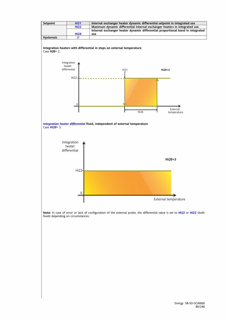
Energy SB-SD-SCW600 80/240
Setpoint Hi21 Internal exchanger heater dynamic differential setpoint in integrated use Hi22 Maximum dynamic differential internal exchanger heaters in integrated use
Hi24 Internal exchanger heater dynamic differential proportional band in integrated use
Hysteresis // Integration heaters with differential in steps on external temperature Case H20= 2.
Integration heater differential fixed, independent of external temperature Case Hi20= 3.
Note: In case of error or lack of configuration of the external probe, the differential value is set to Hi22 or Hi23 (both fixed) depending on circumstances.
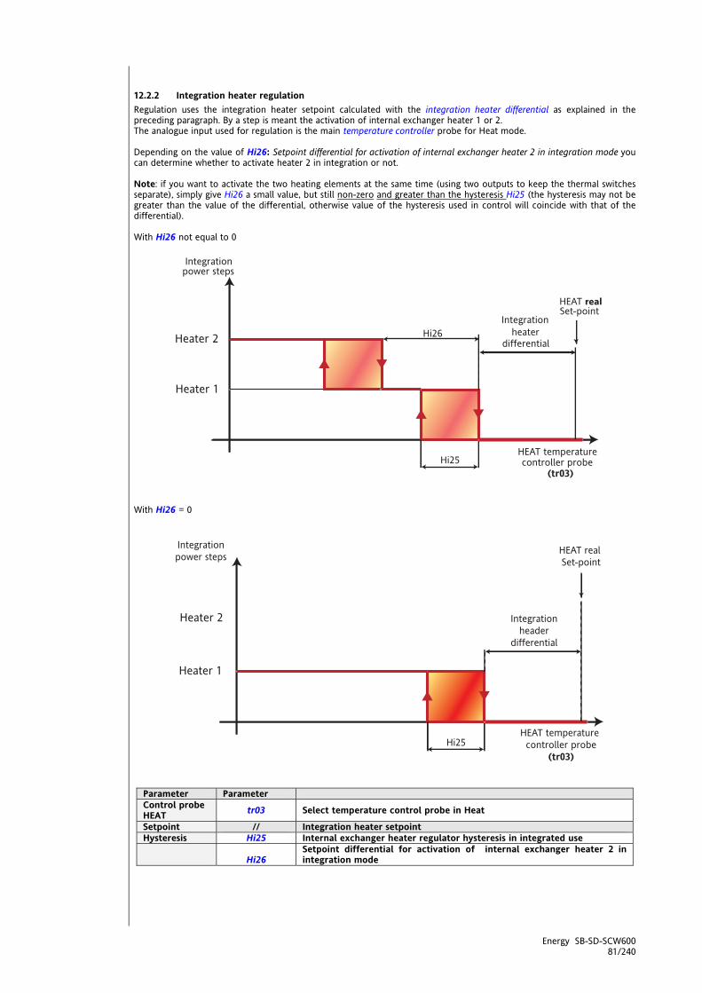
Energy SB-SD-SCW600 81/240
12.2.2 Integration heater regulation Regulation uses the integration heater setpoint calculated with the integration heater differential as explained in the preceding paragraph. By a step is meant the activation of internal exchanger heater 1 or 2. The analogue input used for regulation is the main temperature controller probe for Heat mode. Depending on the value of Hi26: Setpoint differential for activation of internal exchanger heater 2 in integration mode you can determine whether to activate heater 2 in integration or not. Note: if you want to activate the two heating elements at the same time (using two outputs to keep the thermal switches separate), simply give Hi26 a small value, but still non-zero and greater than the hysteresis Hi25 (the hysteresis may not be greater than the value of the differential, otherwise value of the hysteresis used in control will coincide with that of the differential). With Hi26 not equal to 0
With Hi26 = 0
Parameter Parameter Control probe HEAT tr03 Select temperature control probe in Heat
Setpoint // Integration heater setpoint Hysteresis Hi25 Internal exchanger heater regulator hysteresis in integrated use
Hi26 Setpoint differential for activation of internal exchanger heater 2 in integration mode
<IMG INFO>
<IMG INFO>
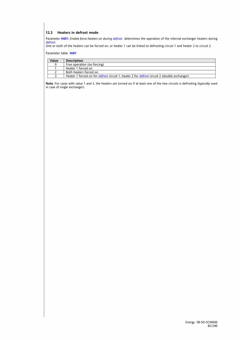
Energy SB-SD-SCW600 82/240
12.3 Heaters in defrost mode Parameter Hi01: Enable force heaters on during defrost determines the operation of the internal exchanger heaters during defrost. One or both of the heaters can be forced on, or heater 1 can be linked to defrosting circuit 1 and heater 2 to circuit 2. Parameter table Hi01
Value Description 0 Free operation (no forcing) 1 Heater 1 forced on 2 Both heaters forced on 3 Heater 1 forced on for defrost circuit 1, heater 2 for defrost circuit 2 (double exchanger)
Note. For cases with value 1 and 2, the heaters are turned on if at least one of the two circuits is defrosting (typically used in case of single exchanger).

Energy SB-SD-SCW600 83/240
13 EXTERNAL EXCHANGER ELECTRIC HEATER PARAMETERS (FOLDER PAR/HE) – ELECTRIC
HEATERS The external exchanger heater parameters can be viewed and modified in folder HE (see User Interface and Parameters chapters). The following must be configured: at least one digital output as external exchanger 1 heater with parameters CL90…CL97 / CL80-CL81 if digital / CL61…CL63 if digital = ±25. at least one digital output as external exchanger 2 heater with parameters CL90…CL97 / CL80-CL81 if digital / CL61…CL63 if digital = ±26. See chapter System configuration (folder PAr/CL-Cr-CF) / Configuration of digital outputs The SB600 controls external exchanger heaters 1 and 2 with antifreeze function (as heat pumps with water external exchanger). The heater control outputs are all and exclusively those outputs with ON/OFF control. The heaters can be used in a variety of ways depending on the type of system. We can have one or two external exchangers (one or two circuits). For greatest configurability: the number of antifreeze heaters can be set; the control analogue input can be determined individually. Enabling The external exchanger heater 1 antifreeze probe is enabled and selected with parameter HE10 - Select probe for antifreeze external exchanger + heater 1. The external exchanger heater 2 antifreeze probe is enabled and selected with parameter HE11 - Select probe for antifreeze external exchanger + heater 2. General conditions of operation In Off the external exchanger antifreeze heaters are immediately and always off. In Standby the external exchanger antifreeze heaters are active if so configured with (HE00 - Enable external exchanger antifreeze heaters in Stand-By). In On, further to the principal regulation specified in the following paragraphs, the following situations (with priority over the principal regulation itself) may occur: The external circuit heaters are immediately turned off during heater block alarms. Note: There are no safety times for heater on/off. Table A - external exchanger heater parameters
heaters Parameter Description Value
0 1
External exchanger (Standby mode)
HE00
Enable external exchanger heater regulator in standby for antifreeze
Heaters disabled Heaters enabled
Heaters Parameter Description Value
0 1 2 3 4
External exchanger Enable heater 1
HE10 Select probe for antifreeze external exchanger + heater 1
External exchanger Enable heater 2
HE11 Select probe for antifreeze external exchanger + heater 2
No probe (antifreeze heater disabled)
External exchanger average temperature circuit 1 and 2
External exchanger inlet water temperature
External exchanger outlet water temperature
External temperature
Heaters Parameter Description Value
External exchanger HE12
External exchanger heater switch on setpoint for antifreeze
Range defined by parameters HE14….HE13 Hysteresis defined by parameter HE15
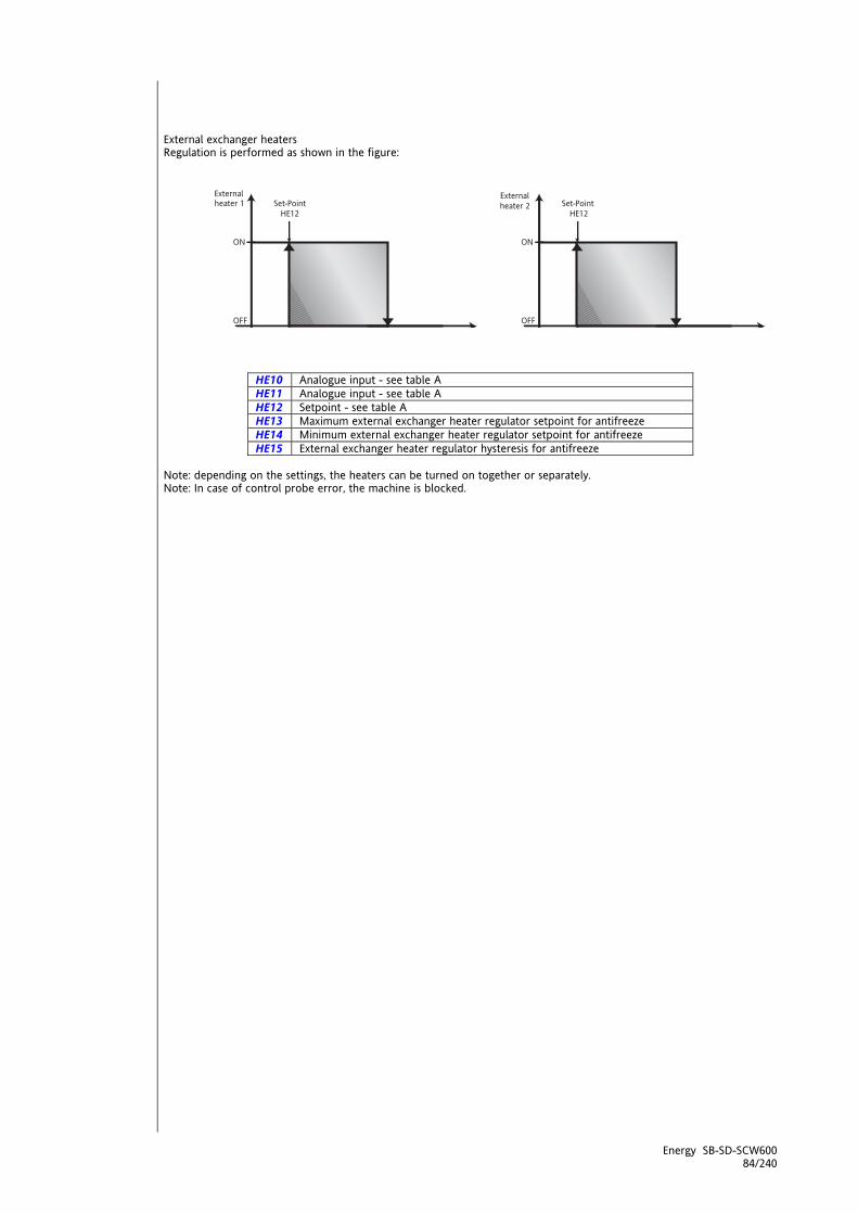
Energy SB-SD-SCW600 84/240
External exchanger heaters Regulation is performed as shown in the figure:
HE10 Analogue input - see table A HE11 Analogue input - see table A HE12 Setpoint - see table A HE13 Maximum external exchanger heater regulator setpoint for antifreeze HE14 Minimum external exchanger heater regulator setpoint for antifreeze HE15 External exchanger heater regulator hysteresis for antifreeze
Note: depending on the settings, the heaters can be turned on together or separately. Note: In case of control probe error, the machine is blocked.

Energy SB-SD-SCW600 85/240
14 AUXILIARY OUTPUT (FOLDER PAR/HA) Auxiliary output parameters can be viewed and configured in folderHA (see User Interface and Parameters chapters) The following must be configured: at least one digital output as Auxiliary Output with parameters CL90…CL97 / CL80-CL81 if digital / CL61…CL63 if digital = ±32. The auxiliary output controller can be used, for example, to control heaters in machines with air condensation to evaporate the condensation water. Enabling The parameter (HA00 - Select probe for auxiliary output regulator) enables the auxiliary output controller. Table A - meaning of parameter HA00:
Value HA00
Probe
0 No probe (auxiliary output disabled) 1 External temperature 2 External exchanger temperature circuit 1 3 External exchanger temperature circuit 2 4 External exchanger inlet water temperature 5 External exchanger outlet water temperature 6 NOT USED
General conditions of operation In Off the auxiliary output is immediately and always off. In Standby the auxiliary output is immediately and always off. In On, further to the principal regulation specified in the following paragraphs, the following situation (with priority over the principal regulation itself) may occur: the auxiliary output is immediately turned off in case of a block alarm for the output itself. Note: There are no safety times for auxiliary output on/off. Auxiliary heaters Regulation is performed as shown in the figure:
Parameter Description HA00 Control probes - see table A HA01 Auxiliary output regulator setpoint HA02 Auxiliary output regulator hysteresis Auxiliary output Auxiliary output
Note: In case of probe error, the machine is blocked.

Energy SB-SD-SCW600 86/240
15 BOILER (FOLDER PAR/BR) The SB600 controls, via a digital output, the pump or the permissive signal for a hot water boiler which is used both for heating and as a supplementary heater (integration mode) for the water heat pump. The boiler control outputs are all and exclusively those outputs with ON/OFF control. There are many types of installation and consequently many ways of using the boiler, especially in residential installations.
15.1 Boiler configuration The boiler is used as a heating power step both for the chiller and the heat pump. Combined with the integration/heating heaters and the compressors (in heat pump mode) it produces hot water on the internal circuit. For maximum configurability, you can set the boiler and other component parameters separately. You can thus determine when to use the boiler power step for heating and when to inhibit it. In both modes, heating and integration, the boiler setpoint can be set as a differential (fixed or proportionally variable depending on the external temperature) with respect to the real setpoint in heat mode. Note. Normally, when there is no heat pump (heating mode), the differential is set as fixed, and to zero (the regulation setpoint coincides with the real heat mode setpoint). Note: if parameter Maximum boiler dynamic differential is set to 0, the setpoint coincides with the real Heat setpoint. Enabling Setting parameter br00: Select boiler modenon-zero enables boiler regulation. General conditions of operation
In Off the boiler is immediately and always off. In Stand-by the boiler is immediately and always off. In On, further to the principal regulation specified in the following paragraphs, the following situation (with
priority over the principal regulation itself) may occur: The boiler is immediately off in case of boiler lock alarm (see alarms table).
In Sanitary Water mode the boiler regulates on the actual Sanitary Water setpoint instead of the actual Heat setpoint
In ACS for Anti-Legionnaire's Disease mode, the boiler regulates on the Sanitary Water setpoint for Anti-Legionnaire's Disease instead of the actual Heat setpoint
Note: There are no safety times for boiler on/off. Operating modes The boiler regulator is only active in Heat mode; the regulation of the setpoint is obtained by subtracting a differential from the real Heat setpoint. The boiler differential can be calculated as a variety of ways which can be selected with parameter Select boiler modebr00. Parameter table br00
Value br00
Description
0 Boiler disabled
1 Boiler with differential Setpoint proportional to external temperature Diagram A
2 Boiler with differential Setpoint in steps dependent on external temperature Diagram B
3 Boiler with differential Fixed setpoint Diagram C

Energy SB-SD-SCW600 87/240
15.1.1 Boiler differential The boiler regulation setpoint is calculated by subtracting a differential from the real Heat setpoint.
Boiler setpoint = real Heat setpoint - Boiler differential In case of heat pump block, the Boiler differential takes the fixed value of parameter br03: boiler differential with heat pump block. This serves to improve the control of the boiler power step in special cases. Boiler differential setpoint proportional to external temperature Example br00 = 1. Diagram A
Parameter Parameter Regulator probe // External temperature
Setpoint br01 Boiler dynamic differential setpoint br02 Maximum boiler differential br04 Boiler differential proportional band
Boiler differential in steps as a function of external temperature Example br00= 2. Diagram B
Parameter Regulator probe // External temperature
Setpoint br01 Boiler dynamic differential setpoint br02 Maximum boiler differential br02 br04 Boiler differential proportional band Hysteresis br05 Boiler regulator hysteresis
<IMG INFO> 311,75 125,05 0 2 56,8 0 -1
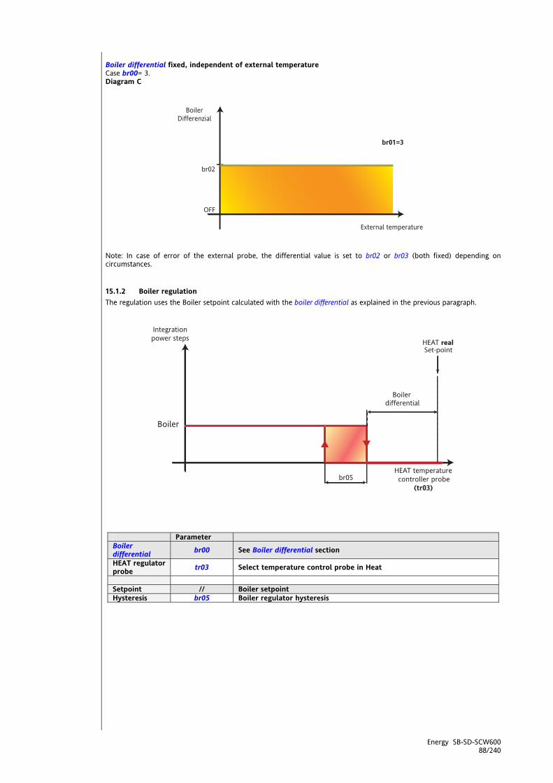
Energy SB-SD-SCW600 88/240
Boiler differential fixed, independent of external temperature Case br00= 3. Diagram C
Note: In case of error of the external probe, the differential value is set to br02 or br03 (both fixed) depending on circumstances.
15.1.2 Boiler regulation The regulation uses the Boiler setpoint calculated with the boiler differential as explained in the previous paragraph.
Parameter Boiler differential br00 See Boiler differential section
HEAT regulator probe tr03 Select temperature control probe in Heat
Setpoint // Boiler setpoint Hysteresis br05 Boiler regulator hysteresis
<IMG INFO>
<IMG INFO> 339,85 188,65 0

Energy SB-SD-SCW600 89/240
16 DEFROST (FOLDER PAR/DF) Defrost parameters can be viewed and configured in the dF folder (see User Interface and Parameters chapters) Defrosting is only possible in HEAT mode. It is used to prevent ice from forming on the surface of the external exchanger. Ice builds up on the external exchanger more often as a result of cold external air containing a high degree of humidity This considerably reduces the thermodynamic efficiency of the machine and can also result in damage to the machine itself. Enabling Defrosting is enabled if:
it is enabled via parameter (dF00 - Enable defrost function = 1,2) Parameter table dF00 Value Description
0 Defrost disabled 1 Simultaneous defrost (in double-circuit plants only) 2 Independent defrost in single or in double-circuit plants (only with separate condensation)
General conditions of operation
In Off defrosting is disabled. In Stand-by defrosting is disabled. In On, further to the principal control specified in the following paragraphs, the following situation may also
arise (with priority to the principal control itself): the defrost request is inhibited/cancelled if antifreeze with heat pump is active.
Types of defrosting SBW600 controls bothSingle defrosting for a single or double external exchanger, and Independent defrosting for the exchangers of two cooling circuits. In the first case, single defrosting, the two circuits defrost at the same time when at least of them requires it. This mode applies to machines with single condensation (parameter FE10: Enable single condensation = 1). The circuit which completes defrosting first, before it resumes normal operation, waits (with compressors off) for the other circuit to complete defrosting. Note: In case of single condensation, two start probes must be configured (on for circuit 1 and one for circuit 2) along with two 2 defrost end probes. The times for starting defrosting are nonetheless independent. In the case of Independent defrosting each circuit defrosts separately. The start and end of the defrost cycle depends on the values of the probes and the parameter settings described below;
defrost Parameter Description dF01 Enable maximum power for non-defrost circuit dF10 Select probe to enable interval count between defrosts dF11 Enable interval count between defrosts setpoint dF12 Setpoint to clear cumulative time between defrosts dF13 Cumulative interval between defrosts
start
dF14 Minimum interval between defrost cycles dF20 Select probe to end defrost dF21 Defrost deactivation setpoint dF22 Maximum defrost time
output
dF23 Dripping time dF30 Maximum dynamic defrost differential
Set Point dF31 Defrost dynamic differential setpoint dF32 Dynamic defrost differential proportional band
Defrosting is done in heat mode, by reversing the cooling cycle, switching the position of the reversal valve and operating the circuit in chiller mode. During defrosting, the reversal valves switch in the same way as for change-overs (see chapter Reversal valve management), with the time given in parameter ST05 - Reversal valve switching delay, and compressor on/off times which refer only to defrosting (parameter CP27 - defrost compressor step/delay minimum). In multi-circuit systems, defrosting can be run separately (independently) or at the same time (single) for the various cooling circuits, depending on the general operational requirements of the plant.

Energy SB-SD-SCW600 90/240
Analogue inputs for defrosting start/end Defrosting can be started in relation to the pressure or temperature measured by the probe selected in parameter dF10: Select probe to enable interval count between defrosts. Defrosting can be ended in relation to the pressure or temperature measured by the probe selected in parameter dF20: Select probe to end defrost. In the double circuit case, each circuit must have an analogue input configured for the function in question. Defrosting function analogue inputs
Description External exchanger temperature circuit 1 External exchanger temperature circuit 2 High pressure input circuit 1 High pressure input circuit 2 Low pressure input circuit 1 Low pressure input circuit 2 External exchanger pressure circuit 1 External exchanger pressure circuit 2
Parameters table dF10 and dF20
Value Description 0 No probe 1 External exchanger temperature (circuit 1 and 2) 2 High pressure input (circuit 1 and 2) 3 Low pressure input (circuit 1 and 2) 4 External exchanger pressure (circuit 1 and 2)
16.1 Defrost
16.1.1 Start defrost Defrosting can be started in relation to the pressure or temperature measured by the probes selected in parameter Select probe to enable interval count between defrosts dF10. If there is a probe error or no probe is configured, start of defrosting depends solely on the effective operating time of the compressors and the parameter Cumulative interval between defrosts dF13. The time between defrosts must be at least equal to the value of parameter Minimum interval between defrost cycles dF14. Note: If dF00 = 2 in systems with two circuits, the minimum time between two defrosts is applied to both circuits therefore defrost cannot occur on the two circuits simultaneously The conditions required for starting defrosting of a circuit are as follows:
When the pressure or temperature detected by the start defrost probe on the circuit drops below the value of the start defrost setpoint and the circuit is supplying at least one power step, the cumulative defrost delay counter is started, the value of which can be set with parameter dF13: Cumulative interval between defrosts.
The start defrost setpoint is a dynamic value calculated on the basis of parameter dF11: Setpoint to enable interval count between defrosts (see relative section).
When the pressure or temperature read by the defrost start probe for the circuit returns above the value of the
defrost start setpoint ot the circuit is no longer delivering any power steps, the cumulative defrost delay count is stopped.
The count is reset to zero after a defrost cycle or after a reset (e.g. power down).
The cumulative defrost delay count is also reset when the temperature or pressure of the probe configured as
defrost start probe rises above the value set in parameter dF12: Setpoint to clear cumulative time between defrosts
When the cumulative defrost delay count terminates (when the time set in the parameter elapses), the circuit
runs a defrost cycle. Given the above, the start time for the defrost cycle corresponds to the time at which the count ends (before valve reversal). Note: In case of change-over, the count is suspended but not reset. In this way, at the next change (e.g. from OFF or Stand-by to Heat), the count resumes from its preceding value. In the case of independent defrosting or a single circuit, defrosting starts only when the compressor safety times are reset, and the conditions for starting defrosting are satisfied (the circuit is delivering at least one power step, etc.). In the case of single defrosting, defrosting starts only when the compressor safety times of both circuits are reset and the conditions for starting defrosting on the requesting circuit are satisfied. The two circuits defrost in a fully harmonised manner.
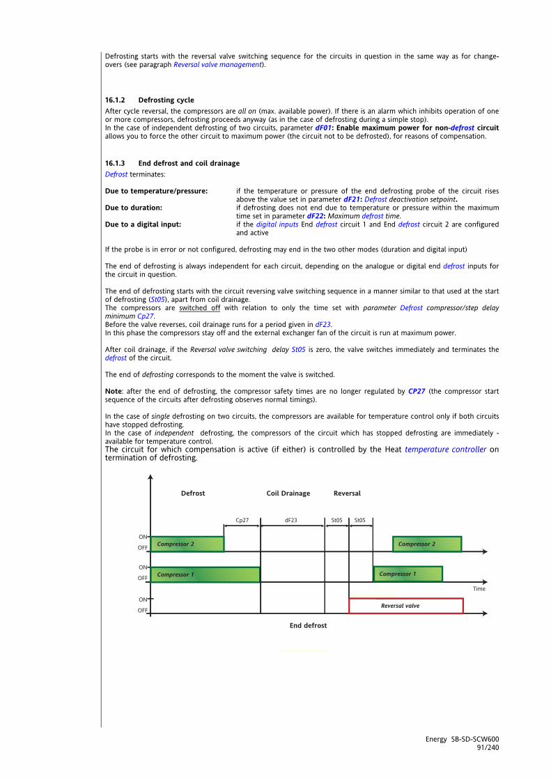
Energy SB-SD-SCW600 91/240
Defrosting starts with the reversal valve switching sequence for the circuits in question in the same way as for change-overs (see paragraph Reversal valve management).
16.1.2 Defrosting cycle After cycle reversal, the compressors are all on (max. available power). If there is an alarm which inhibits operation of one or more compressors, defrosting proceeds anyway (as in the case of defrosting during a simple stop). In the case of independent defrosting of two circuits, parameter dF01: Enable maximum power for non-defrost circuit allows you to force the other circuit to maximum power (the circuit not to be defrosted), for reasons of compensation.
16.1.3 End defrost and coil drainage Defrost terminates: Due to temperature/pressure: if the temperature or pressure of the end defrosting probe of the circuit rises
above the value set in parameter dF21: Defrost deactivation setpoint. Due to duration: if defrosting does not end due to temperature or pressure within the maximum
time set in parameter dF22: Maximum defrost time. Due to a digital input: if the digital inputs End defrost circuit 1 and End defrost circuit 2 are configured
and active If the probe is in error or not configured, defrosting may end in the two other modes (duration and digital input) The end of defrosting is always independent for each circuit, depending on the analogue or digital end defrost inputs for the circuit in question. The end of defrosting starts with the circuit reversing valve switching sequence in a manner similar to that used at the start of defrosting (St05), apart from coil drainage. The compressors are switched off with relation to only the time set with parameter Defrost compressor/step delay minimum Cp27. Before the valve reverses, coil drainage runs for a period given in dF23. In this phase the compressors stay off and the external exchanger fan of the circuit is run at maximum power. After coil drainage, if the Reversal valve switching delay St05 is zero, the valve switches immediately and terminates the defrost of the circuit. The end of defrosting corresponds to the moment the valve is switched. Note: after the end of defrosting, the compressor safety times are no longer regulated by CP27 (the compressor start sequence of the circuits after defrosting observes normal timings). In the case of single defrosting on two circuits, the compressors are available for temperature control only if both circuits have stopped defrosting. In the case of independent defrosting, the compressors of the circuit which has stopped defrosting are immediately -available for temperature control. The circuit for which compensation is active (if either) is controlled by the Heat temperature controller on termination of defrosting.

Energy SB-SD-SCW600 92/240
16.2 Start defrost setpoint In very dry and cold climates, it is good to be able to vary the reference temperature for the start of defrosting as a function of the external temperature. This regulator linearly compensates the defrosting start temperature or pressure with a positive or negative differential value according to the external temperature. The real setpoint for the start of defrosting is calculated by adding this dynamic differential to the value of parameter dF11: Setpoint to enable interval count between defrosts. Enabling The regulator is enabled by setting parameter dF30 Maximum dynamic defrost differential to a value other than zero. Furthermore, an analogue input must be configured as external temperature.
defrost Parameter Description External temperature External temperature
Differential dF30 Maximum dynamic defrost differential Set Point dF31 Defrost dynamic differential setpoint
dF32 Dynamic defrost differential proportional band Note: In case of error of the external probe, the differential value is set to zero (compensation disabled).
16.3 Management of defrost alarms For the actuation of loads during alarms, see the diagnostics chapter. To summarise, and specifically for defrosting, if probe errors or alarms occur which lock the compressors, the start defrost and end defrost cycles are already defined and are typically based on parameter timings. E.g.: If during defrosting the compressors are made unavailable by alarms, defrosting will terminate when the maximum time expires. It may terminate differently if the compressors become available again during the defrosting cycle.
16.4 Manual defrost EnergySBW600 can force defrost manually by pressing and holding the [UP] key. Manual defrost is possible when:
dF00 = 1,2 UI20 -Enable defrost function from key if the temperature / pressure of the external exchanger is less than the value set in parameter dF01 - Enable
maximum power for non-defrost circuit Defrost starts in the sequence described in the section about "Start Defrost"
the defrost LED is blinking. End defrost takes place as described in the section about "End Defrost"
16.5 Power failure during defrost If a power failure happens during defrosting, the procedure will be cancelled. All timings will be cancelled and restarted.

Energy SB-SD-SCW600 93/240
17 DYNAMIC SETPOINT (FOLDER PAR/DS) Dynamic setpoint parameters can be viewed and configured in folder dS (see User Interface and Parameters sections). The regulator is used to modify the setpoint automatically depending on external conditions. This modification is obtained by adding a negative or positive value to the setpoint (offset or differential) depending on:
analogue input set as dynamic setpoint input NOTE: the applies only for AIL3 (CL32=25) / AIE3 (CE32=25) or AIL4 (CL33=25) / AIE4 (CE33=25)
or External temperature
This function has two purposes: to save energy or to run the machine in extreme external temperatures. Enabling Dynamic setpoint a) As a function of external temperature is enabled if:
The dynamic setpoint activation/selection parameter dS00= 1 or 2 b) As a function of the dynamic setpoint input
probe AI3 (analogue inputs) is configured as an dynamic setpoint input (CL32=25) / (CE32=25) or probe AI4 (analogue inputs) is configured as an dynamic setpoint input (CL33=25) / (CE33=25)
Note:
these two options (a) and (b) are independent If the external temperature probe is in error, the associated dynamic differential is annulled (function disabled) The dynamic setpoint input must be a voltage (V) or current (I) input, it may not be an NTC temperature probe.
The Min and Max values of the graphs are associated with the Min (start of scale value) and Max (fullscale value) values of the input itself. If the dynamic setpoint input is in error, the associated dynamic differential is annulled (function disabled)
The Economy LED flashes when this function is active (if so configured: UI07=1)
17.1 Modification (decalibration) of the setpoint as a function of the dynamic setpoint input
17.1.1 Modification (decalibration) of the setpoint as a function of the dynamic setpoint input with positive offset.
The following figure shows decalibration in both cooling and heating modes:
Positive Offset
Note The dynamic setpoint input must be a voltage (V) or current (I) input, it may not be an NTC temperature probe, in other words, CL02/CL03= 3,4,5 or 6 The Min and Max values of the graphs are associated with the Min (start of scale value) and Max (fullscale value) values of the input itself, in other words
Min = CL11 for AI3; CL13 for AI4 Max = CL10 for AI3; CL12 for AI4
Modification based on the
dynamic setpoint input with positive
offset
65

Energy SB-SD-SCW600 94/240
17.1.2 Modification (decalibration) of the setpoint as a function of the dynamic setpoint input with negative offset.
See above
Negative Offset
17.2 Modification (decalibration) of the setpoint based on the external temperature The setpoint can be decalibrated based on external temperature either proportionally or with a fixed decalibration; this is set with parameter dS00 - External temperature controller dynamic differential selection This allows enabling/selecting the temperature controller dynamic digital differential
0 = disabled 1 = Proportional 2 = Fixed (by steps)
17.2.1 Modification (decalibration) of the setpoint based on the external temperature (dS00=1) Proportional decalibration of the setpoint with positive differential (offset). The figure shown above shows decalibration in both cooling and heating modes:
Positive Offset
Proportional decalibration of the setpoint with negative differential (offset). See above
Negative Offset
Cool Heat dS01 dS02 Temperature controller dynamic differential proportional band in Cool / Heat dS03 dS04 Maximum temperature controller dynamic differential in Cool / Heat dS05 dS06 Temperature controller dynamic differential setpoint in Cool / Heat
Ext. Temp: External temperature
Modification based on the
dynamic setpoint input with
negative offset
Modification based on the
external temperature with
positive offset
Modification based on the
external temperature with
negative offset
5 6
IMG INFO
<IMG INFO> 425,25 110,15 0 2 0,05 0 -1
<IMG INFO>

Energy SB-SD-SCW600 95/240
17.2.2 Fixed modification (decalibration) of the setpoint (dS00=2) Differential > 0 Band < 0
Differential < 0 Band < 0
Differential > 0 Band > 0
Differential < 0 Band > 0
Cool Heat
dS01 dS02 Temperature controller dynamic differential proportional band in Cool / Heat
dS03 dS04 Maximum temperature controller dynamic differential in Cool / Heat
dS05 dS06 Temperature controller dynamic differential setpoint in Cool / Heat
Temp Ext Air: External temperature Offset: differential
<IMG INFO> 197,3 126,35 0
<IMG INFO>
<IMG INFO>

Energy SB-SD-SCW600 96/240
<IMG INFO> 23,6 27,7 1 2 79 35
18 ADAPTIVE (FOLDER PAR/AD) Chillers generally contain a water accumulation tank. The purpose of these tanks is to create sufficient thermal inertia to stop the compressor from repeatedly switching on and off in periods in which the temperature requirements in the area to be cooled are relatively few (switching repeatedly on and off will reduce the life time of compressors). A water accumulator increases the thermal capacity and provides the inertia required to extend running time. Nevertheless, water accumulation is also a substantial cost and also adds to the minimum dimensions of the machine. Adaptive function parameters can be viewed and configured in the Ad folder (see chapters on User Interface and Parameters). By adjusting the setpoint and hysteresis, the Adaptive function simulates electronically the inertia of a water accumulator, meaning it can be used less. Enabling Use parameter Ad00 - Select no accumulation mode when set not equal to zero enables the function and enables selecting the amount to which the adaptive function temperature differential is to be added or subtracted.
0 1 2 2
Ad00 Select no accumulation mode Accumulation disabled Setpoint Hysteresis Setpoint +
hysteresis General conditions of operation
In Off the adaptive function is disabled. In Stand-by the adaptive function is disabled. In On the adaptive function is enabled.
MT minimum time and ET real time Note that compressor on/off times must respect safety time delays: The function analyses actual running time of the compressor (ET) comparing it with the preset minimum running time (MT). The minimum time (MT) is set in parameter Ad06 - Reference compressor on time for adaptive accumulation
Parameter Description
MT
Ad06 Reference compressor on time for accumulation offset
Real running time (ET) is recorded automatically by the device
Type of plant ET Single circuit
2 / 4 compressors / Segmented compressors
Count [first compressor on / first partialization, last resource switched off]
Double circuit 1 / 2 compressors /
Segmented compressors
Count [first compressor on / first partialization, last resource switched off]
Independently of the circuits
Ordinary compressor Count [compressor on, compressor off]
18.1 Adaptive function with setpoint modification If ET<MT: when the compressor switches off, the operating setpoint is changed to a value equal to the adaptive offset (AO) according to the formula below:
AO=((MT - ET)* Ad01)/10 + Ad02 Where:
Ad01 Accumulation offset constant Ad02 Accumulation offset differential
Minimum time MT
Real time ET
ET<MT example

Energy SB-SD-SCW600 97/240
COOLING MODE
ET<MT example If the real running time (ET) is less than the minimum time(MT), each time the compressor switches off, the adaptive offset is subtracted from the setpoint.
Cycle 0:
Setpoint for cycle 0: SET(0) = SET (COOL) Hysteresis for cycle 0: HYSTERESIS (0) = HYSTERESIS (COOL) Compressor ON: SET (0)+HYSTERESIS (0) ---> SET (COOL) +HYSTERESIS(COOL)** Compressor OFF: SET (0)
Cycle 1: Setpoint for cycle 1: SET(1) = SET (0) - AO(1) = SET(COOL)-AO(1) Compressor ON: SET (0)+HYSTERESIS (0) ---> SET (COOL) +HYSTERESIS(COOL)** Compressor OFF: SET (0) - AO(1) = SET (COOL)** - AO(1)
Cycle 2: Setpoint for cycle 2: SET(2) = SET (1) - AO(2) Compressor ON: SET (0)+HYSTERESIS (0) ---> SET (COOL) +HYSTERESIS(COOL)** Compressor OFF: SET (0) - AO(2) = SET (COOL)** - AO(2)
…
ET>MT example See differential regression
HEATING MODE Same as heating example. The offset is ADDED to the setpoint:
SET(0) = SET (HEAT) SET(1) = SET(HEAT)+AO(1) SET(2) = SET(HEAT)+AO(2)
… Note that in both modes, the compressor on temperature is the same for each operating cycle, even when the adaptive function is activated. This extends the zone between the setpoint and on temperatures, reducing the number of times the compressor switches on and off and thereby reducing any overlap with safety times.
Cooling mode Adaptive function with setpoint modification (Ad00=0) Setpoint modification after calculation of AO1
SET1 = SET(1), SET2=SET(2)
Adaptive function Setpoint
modification in cooling
Adaptive function Modification of
setpoint in heating
<IMG INFO> 212,7 143,65 0 2 -4,95 -142,9 -1

Energy SB-SD-SCW600 98/240
18.2 Adaptive function with hysteresis modification Adaptive function with hysteresis modification (Ad00=1) Hysteresis modification after calculation of AO1
18.3 Adaptive function with setpoint and hysteresis modification
Adaptive function with setpoint and hysteresis
modification (Ad01=2) Setpoint and hysteresis modification after calculation of
AO1
18.4 Setpoint regression If ET MT: If the cycle time is long enough (and greater than MT), regression of the real setpoint occurs: for each interval of Ad05 (from the start of the cycle), the setpoint is modified by the value set in Ad02.
in cooling, the setpoint (real for cycle N) is increased: after Ad05: SET(N) + Ad02 after 2*Ad05: SET(N) + 2*Ad02 and so on until the maximum value (setpoint / hysteresis)
in heating, the setpoint is reduced as above, down to the minimum value (setpoint / hysteresis) Hence for long cycle times, the "adaptive" function balances out making the cycle times compatible with compressor timings.
ETMT example
<IMG INFO>
IMG INFO
<IMG INFO> 214,6 158,45 0 2

Energy SB-SD-SCW600 99/240
Cooling mode
Setpoint regression
Parameter Description Parameter
Ad01 Accumulation offset constant See
Modify setpoint offset calculation formula
See Modify setpoint offset calculation
formula Ad02 Accumulation offset differential See
Setpoint regression
Ad03 Block accumulation offset setpoint in cooling mode See Protection in cooling mode
Ad04 Block accumulation offset setpoint in heating mode See Protection in heating mode
Ad05 Compressor on time for accumulation offset regression See setpoint regression
Ad06 Reference compressor on time for accumulation offset See MT
18.5 Protection COOL If the outlet temperature < Ad03 during general cycle n, the controller performs the following actions: Switches off the compressor (or compressors) Clears the adaptive offset AO(n) = 0; the next cycle recommences with the original setpoint and hysteresis This adjustment can be considered a precursor of the antifreeze alarm (the cycle stops without generating an alarm) should the adaptive function lead to a very low real setpoint. We recommend you set Ad03 > AL12 Internal circuit antifreeze alarm regulator setpoint HEAT If the outlet temperature > Ad04 during general cycle n, the controller performs the following actions: Switches off the compressor (or compressors) Clears the adaptive offset AO(n) = 0; the next cycle recommences with the original setpoint and hysteresis This adjustment can be considered a precursor of the high pressure alarm (the cycle stops without generating an alarm) should the adaptive function lead to a very high real setpoint. To set Ad06, we recommend you refer to the high pressure safety devices in use (pressure switch configuration, type of refrigerant used, and so on) Note: if the plant is of the two circuit type and two water temperature sensors are configured on circuit 1 and 2 primary output, consider the minimum of the two values.
Energy SB-SD-SCW600 100/240
<IMG INFO> 42,9 29,75 1 2 51 28 35
19 ANTIFREEZE PARAMETERS WITH HEAT PUMP (FOLDER PAR/AF) - ANTIFREEZE Anti-freeze parameters can be viewed and configured in folder AF (see User Interface and Parameters chapters). The anti-freeze function with heat pump serves to prevent breakdowns due to internal heat exchanger icing (typically in machines with water-type internal heat exchangers). SB600 enables control of machines with one or two cooling circuits and one or two internal heat exchangers. The anti-freeze function with heat pump is controlled separately for each cooling circuit. The function is always active in any machine operating state, i.e. cooling, heating and standby. Anti-freeze function with heat pump is enabled via parameter (AF00 - Select antifreeze probe with circuit 1 heat pump ≠ 0) via parameter (AF01 - Select antifreeze probe with circuit 2 heat pump ≠ 0) The Heating LED flashes when this function is active. Mode change is disabled when this function is enabled. Defrosting is disabled when this function is enabled. Analogue inputs for anti-freeze function with heat pump The analogue inputs used for regulation are selected distinctly for each cooling circuit, using parameters AF00 - Select antifreeze probe with circuit 1 heat pump AF01 - Select antifreeze probe with circuit 2 heat pump Note: For machines with a single circuit AF01 - Select antifreeze probe with circuit 2 heat pump must be set = 0.
Value AF00 / AF01 Probe 0 No probe (anti-freeze function with heat pump disabled) 1 Internal exchanger water/air inlet temperature 2 Internal exchanger water/air outlet temperature 3 Circuit 1 internal exchanger water outlet temperature 4 Circuit 2 internal exchanger water outlet temperature 5 Circuit 1 and 2 internal exchanger water outlet minimum temperature
General conditions of operation In Off the anti-freeze function with heat pump is disabled. In Stand-by the anti-freeze function with heat pump is enabled, as in On. In On, further to the principal regulation specified in the following paragraphs, the following situation (with priority over the principal regulation itself) may occur: anti-freeze function with heat pump inhibited during defrosts. NOTE: The valve reverses with a delay ST05 - Reversal valve switching delay. Furthermore, during the anti-freeze phase, the compressors run at maximum power and are turned off and on with reference only to the delay CP27 - Defrost compressor step/delay minimum Heat pump activation The function is enabled (°) if the temperature measured Circuit 1: by the anti-freeze with heat pump probe for circuit 1 < AF02 - Anti-freeze regulator setpoint with heat pump Circuit 2: by the anti-freeze with heat pump probe for circuit 2 < AF02 - Anti-freeze regulator setpoint with heat pump (°) the heat pump is activated if previously switched off; if previously activated, it remains active
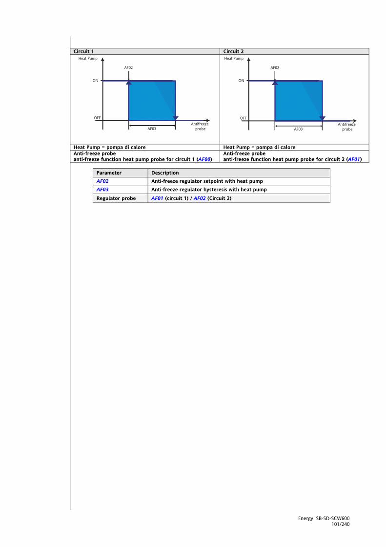
Energy SB-SD-SCW600 101/240
Circuit 1 Circuit 2
Heat Pump = pompa di calore Heat Pump = pompa di calore Anti-freeze probe anti-freeze function heat pump probe for circuit 1 (AF00)
Anti-freeze probe anti-freeze function heat pump probe for circuit 2 (AF01)
Parameter Description AF02 Anti-freeze regulator setpoint with heat pump AF03 Anti-freeze regulator hysteresis with heat pump Regulator probe AF01 (circuit 1) / AF02 (Circuit 2)
<IMG INFO> 219,9 128,45 0 2 0,75 127 75
<IMG INFO> 219 128,35 0 2 -5 15
Energy SB-SD-SCW600 102/240
20 SANITARY WATER AND ANTI-LEGIONNAIRE'S DISEASE (FOLDER PAR/AS) Small/medium installations (typically residential installations) require “integrated” management of sanitary water (also referred to as ACS) by means of the heat pump system (for heating and cooling the interior environment). In practice, this involves controlling the sanitary water temperature (ACS temperature) in a dedicated accumulator. The switch between 'normal' mode (heating/cooling) and ACS mode can occur in 2 ways, depending on the type of system:
With ACS Valve: the flow will be diverted from the heating/cooling circuit to the ACS accumulator With ACS Pump: the heating/cooling circuit pump will be switched off and the ACS accumulator pump switched
on Type of system The type of system is configured using parameter AS00 - Select ACS mode Enabling When parameter AS00 - Select ACS mode is different from zero, the regulator is enabled. The possible values of parameter AS00 are:
0 = Disabled 1 = Enabled only heat pump for sanitary water system with sanitary water valve 2 = Enabled only sanitary water heater 3 = Enabled sanitary water heat pump and heater system with sanitary water valve 4 = Enabled only heat pump for sanitary water system with sanitary water pump 5 = Enabled only sanitary water heater 6 = Enabled sanitary water heat pump and heater system with sanitary water pump
Refer also to the following table where the AS00 values are indicated in relation to the type of system used
Par. Description value 0 1 or 4 2 or 5 3 or 6
Enabling AS00 Select ACS mode disabled Heat pump
only sanitary water heater
Heat pump +
sanitary water heater
Sanitary water valve
AS00 = 1 system with sanitary water valve
AS00 = 3 system with
sanitary water valve
system
Sanitary water pump
AS00 = 4 system with sanitary water pump
AS00 = 6 system with
sanitary water pump
Notes.
The term heat pump actually denotes the entire machine (e.g. including the integrated internal exchanger heaters, if any)
Since the behaviour of the sanitary water heater is independent from the type of system, the values 2 and 5 determine the same device behaviour.
When parameters Anti-legionnaire's disease event duration, Monday – Tuesday - etc. AS25, AS26… are different from zero (at least one must be) the Anti-legionnaire's disease function is enabled .Furthermore the RTC must be present and enabled for operation (it must not be faulty and/or not set, for further details refer to the specific alarms)
General conditions of operation
In Off the regulator is switched off immediately and continuously. In Standby the regulator is on, with exclusive reference to activation of the ACS antifreeze heater. In On, in addition to the main control specified in subsequent paragraphs, the following situations are also
possible (with priority given to the main control itself): If there is an error in the sanitary water temperature sensor, the compressor associated with that sensor is
disabled The ACS valve / pump is immediately switched off in the event of valve / pump shutdown alarms The ACS heater is immediately switched off in the event of heater shutdown alarms On start-up of SBW600 (power on or reboot from OFF or Stdby), ACS mode is inhibited for 120 seconds in
order to prevent multiple settings competing on start-up, with impulsive activations of the loads (e.g. internal pump).
Sanitary Water Setpoint Regulation occurs on the actual ACS Setpoint. The Actual Setpoint is determined by the following contributing factors:
At start-up of the instrument, the Sanitary Water Setpoint = AS01 - ACS setpoint If Time Bands are active (tE00 - Enable time band operation = 1) the Sanitary Water Setpoint will be
determined by the ACS Set Point of the corresponding event / profile (see Time Bands section (folder PAr/tE)) If AS11 - ACS set point dynamic constant is different from zero then the Dynamic ACS Setpoint function is
activated on the Sanitary Water Setpoint
Energy SB-SD-SCW600 103/240
20.1 Sanitary Water in HEAT mode Sanitary water consent In Sanitary Water mode, the machine's operation is governed by the request/consent concept. Consent may be given (with resulting switchover from normal mode to the mode determined by the Sanitary Water regulator) if and only if all of the following conditions are satisfied:
Sanitary Water Setpoint not reached (a function of the temperature of the ACS accumulator – See diagram A the time AS10 - ACS minimum deactivation/activation time has elapsed NO Anti-Legionnaire's Disease period is in progress*
*example: Saturday 21.30. AS40 different from 0; AS41 = 22, AS42 = 0 This request, which was described above, takes priority over the "normal" ACS heating request.
Diagram A Sanitary water CONSENT
Par. Description AS04 ACS hysteresis AS01 ACS setpoint
AS02-AS03 Note: using the parameters:
AS02 - ACS minimum setpoint AS03 - ACS maximum setpoint
It is possible to limit the maximum and minimum configuration values of AS01 Setpoint Actual ACS Setpoint
Control sensor Sanitary water temperature
Regulation, machine in HEAT In the event of a sanitary water heating request:
the machine remains in Heat Pump mode (and maintains the same control sensor that it uses in normal Heat mode) but modifies the control setpoint from actual Heat Setpoint to AS01 -ACS Setpoint (ACS) with AS05 - ACS disengage setpoint differential
the ACS valve / pump is activated with the following actions: o machine with ACS valve: the ACS valve is activated without switching off the internal pump o machine with ACS pump: the ACS pump is activated at the same time as the internal pump is
switched off; to prevent flow switch alarms, it is necessary to re-enter the time AL14 - Flow switch alarm bypass
ACS heater: see corresponding paragraph ACS disengage Once the machine has been "disengaged" to heat the sanitary water for Anti-Legionnaire's disease, it will continue to do so until at least one of the following conditions is satisfied:
tACS accumulator sensor reaches the actual ACS setpoint - see figure B the Heat control sensor (which typically is not the ACS accumulator sensor) reaches a certain value, equal to the
AS01 -ACS Setpoint (ACS) plus a specifiable differential, which takes account of the temperature difference that may exist between the ACS accumulator and the position of the Heat control sensor, parameter AS05 - see figure C
the time set using parameter AS09 - ACS maximum activation time has elapsed an Anti-Legionnaire's Disease period is starting
When normal mode and the actual Heat (or Cool) setpoint are restored, except in the event of request/consent for machine operation in ACS for Anti-Legionnaire's Disease – see corresponding paragraph All considerations regarding the actions adopted during switchovers apply. If normal operating mode is restored, the ACS valve / pump is switched off with the following actions:
machine with ACS valve: the ACS valve is switched off, the internal pump will continue to function if required for normal operating mode
machine with ACS pump: the internal pump is activated at the same time as the ACS pump is deactivated; to prevent flow switch alarms, it is necessary to re-enter the time AL14 - Flow switch alarm bypass
Sanitary water temperature
AS04
Actual ACS setpoint
ACS heating
OFF
ON

Energy SB-SD-SCW600 104/240
Diagram B sanitary water DISENGAGE
SETPOINT REACHED
Diagram C
sanitary water DISENGAGE
Diagram Par. Description
AS02-AS03
Note: using the parameters: AS02 - ACS minimum setpoint AS03 - ACS maximum setpoint
It is possible to limit the maximum and minimum configuration values of AS01
B Setpoint Actual ACS Setpoint
B Control sensor Sanitary water temperature
C AS01 ACS Setpoint C AS05 ACS disengage setpoint differential
C Control sensor AIn HEAT control sensor
Sanitary water temperature
Actual ACS setpoint
ACS heating
OFF
ON
AInAS05
AS01
ACSHeating
OFF
ON
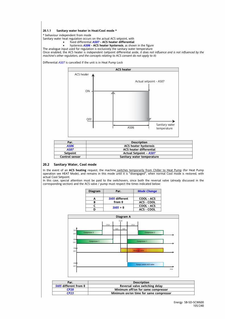
Energy SB-SD-SCW600 105/240
20.1.1 Sanitary water heater in Heat/Cool mode * * behaviour independent from mode Sanitary water heat regulation occurs on the actual ACS setpoint, with
fixed differential AS07 - ACS heater differential hysteresis AS06 - ACS heater hysteresis, as shown in the figure
The analogue input used for regulation is exclusively the sanitary water temperature Once enabled, the ACS heater is independent (setpoint differential aside, it does not influence and is not influenced by the machine's other regulators, and the concepts relating to ACS consent do not apply to it) Differential AS07 is cancelled if the unit is in Heat Pump Lock
ACS heater
Par. Description AS06 ACS heater hysteresis AS07 ACS heater differential
Setpoint Actual Setpoint – AS07 Control sensor Sanitary water temperature
20.2 Sanitary Water, Cool mode In the event of an ACS heating request, the machine switches temporarily from Chiller to Heat Pump (for Heat Pump operation see HEAT Mode), and remains in this mode until it is "disengaged", when normal Cool mode is restored, with actual Cool Setpoint. In this case, special attention must be paid to the switchovers, since both the reversal valve (already discussed in the corresponding section) and the ACS valve / pump must respect the times indicated below:
Diagram Par. Mode Change
A COOL - ACS B
St05 different from 0 ACS - COOL
C COOL - ACS D St05 = 0 ACS - COOL
Diagram A
Par. Description St05 different from 0 Reversal valve switching delay
CP20 Minimum off/on for same compressor CP23 Minimum on/on time for same compressor
Sanitary water temperature
ACS heater
Actual setpoint - AS07
ON
OFF
AS06 IMG INFO
OFF
ON
time
OFF
ON
OFF
ONReversal valve
Compressor 2
Compressor 1 Compressor 1
Pumps switch ACS valve
OFF
ON
CP24 CP23
CP20
Compressor 2
St05St05

Energy SB-SD-SCW600 106/240
Par. Description CP24 Minimum off/off time for different compressors
The switchover occurs with the following measures:
machine with ACS valve: the ACS valve is activated after the time St05 - Reversal valve switching delay from the valve switchover (to switch-on of the first compressor, unless other safety timings further delay said compressor), without switching off the internal pump. If in normal mode the compressors are switched off, the internal exchanger water pump can also be switched off (e.g. operation enabled on request): in this case the pump will switch on at the same time as the ACS mode is activated, resulting in the delayed switch-on of the compressors due to the need for pre-pumping.
machine with ACS pump: the ACS pump is activated after the time St05 - Reversal valve switching delay from the valve switchover (to switch-on of the first compressor, unless other safety timings further delay said compressor): the internal pump is switched off at the same time; to prevent flow switch alarms it is necessary to re-enter the time AL14 - Flow switch alarm bypass
Diagram B
Par. Description St05 different from 0 Reversal valve switching delay
CP20 Minimum off/on for same compressor CP23 Minimum on/on time for same compressor CP24 Minimum off/off time for different compressors
The switchover occurs with the following actions:
machine with ACS valve: the ACS valve is deactivated after the time St05 - Reversal valve switching delay from the valve switchover (to switch-on of the first compressor, unless other safety timings further delay said compressor), without switching off the internal pump (this water pump may be switched off according to normal mode logic (e.g. operation enabled on request and compressors off).
machine with ACS pump:: the internal exchange pump is activated after the time St05 - Reversal valve switching delay from the valve switchover (to switch-on of the first compressor, unless other safety timings further delay said compressor), the ACS is switched off at the same time; to prevent flow switch alarms it is necessary to reset the time AL14 - Flow switch alarm bypass.
OFF
ON
time
OFF
ON
OFF
ONReversal valve
Compressor 2
Compressor 1 Compressor 1
Pumps switch ACS valve
OFF
ON
CP24 CP23
CP20
Compressor 2
St05St05

Energy SB-SD-SCW600 107/240
Diagram C
Diagram D
Par. Description St05 = 0 Reversal valve switching delay
20.2.1 Dynamic ACS setpoint The Dynamic ACS Setpoint function consists of modifying the actual ACS setpoint according to the system's thermal efficiency. In fact, it may occur that (e.g. due to incorrect dimensioning of the system) the machine never manages to reach the actual ACS setpoint. Based on previous considerations, in this case the machine would exit ACS mode either due to timeout expired (AS09 - ACS maximum activation time) or due to Heat control setpoint reached (AS01 + AS05). The Dynamic ACS Setpoint function calculates and updates the maximum sanitary water temperature which the system can achieve under those particular conditions. In this way, the system is in any case "guaranteed" to exit from ACS mode due to attainment of the ACS Setpoint. Enabling This function is enabled by setting parameter AS11 - ACS setpoint dynamic constant to a value different from zero. You must also configure all of the following analogue inputs as:
water delivery temperature. water return temperature. ACS temperature
The Dynamic ACS Setpoint function will calculate the new ACS setpoint as the minimum value between
Actual Setpoint (*) ACS maximum water temperature achievable as a function of the system
Where (*) is a function of the parameters AS11 - ACS setpoint dynamic constant AS12 - ACS system maximum temperature
OFF
ON
time
OFF
ON
OFF
ONReversal valve
Compressor 2
Compressor 1
Pumps switch ACS valve
OFF
ON
<IMG INFO>
OFF
ON
time
OFF
ON
OFF
ONReversal valve
Compressor 2
Compressor 1
Pumps switch ACS valve
OFF
ON
<IMG INFO>

Energy SB-SD-SCW600 108/240
20.3 Sanitary water regulation, AS mode During operation in Heat or Cool mode, the controller/machine (heat pump) meet ACS (or ACS for AL) heating needs if there is a request and provided the necessary conditions are met, otherwise they meet system needs (Heat or Cool). AS mode is useful in the event that (e.g. due to the current season or the type of system) it is not necessary to meet system needs. In other words in AS mode, the controller/machine (heat pump) are only activated if there is a need for ACS (or ACS for AL) heating, according to the same process as that described previously, otherwise there is no actuation. The above indications also apply to defrost (must be managed as normal!).
20.4 Anti-Legionnaire's Disease The Anti-Legionnaire's Disease function eliminates Legionnaire's disease bacteria, which reside in water sources; these bacteria are typically destroyed if the water temperature rises above 60°C for a certain period of time. Anti-Legionnaire's Disease period An anti-legionnaire's disease period can be activated on each day of the week with a configurable start time and duration:
Description
Duration of event
(0= disabled) Par.
Event (start) hour Par.
Event (start) minutes Par.
day 1 (Monday) AS25 AS26 AS27 day 2 (Tuesday) AS28 AS29 AS30 day 3 (Wednesday) AS31 AS32 AS33 day 4 (Thursday) AS34 AS35 AS36 day 5 (Friday) AS37 AS38 AS39 day 6 (Saturday) AS40 AS41 AS42 day 7 (Sunday) AS43 AS44 AS45
Note. The Anti-Legionnaire's disease period (duration of event) must be of suitable length, otherwise there is the risk that AS20 - ACS setpoint for anti-legionnaire's disease is never reached. If so an Er48 Anti-legionnaires alarm will raise up. The automatic alarm reset when the setpoint will be reached. ACS setpoint for anti-legionnaire's disease Regulation always occurs on the ACS setpoint for anti-legionnaire's disease AS20 ACS consent for anti-legionnaire's disease In the same way as for the "normal" ACS regulator, the request/consent concept applies to machine operation in ACS for Anti-Legionnaire's Disease. Consent may be given (with resulting switchover from normal mode, or from ACS mode, to the mode determined by the ACS regulator for Anti-Legionnaire's disease) if and only if all of the follow conditions are satisfied:
Anti-Legionnaire's disease period in progress* *example: Saturday 22.30. AS40 different from 0; AS41 = 22, AS42 = 0
ACS setpoint for Anti-Legionnaire's Disease not reached (a function of the temperature of the ACS accumulator – See diagram A
the time AS23 - ACS minimum deactivation/activation time for anti-legionnaire's disease has elapsed This request, which was described above, takes priority over the "normal" ACS heating request.
Diagram A Anti- Legionnaire's disease CONSENT
Par. Description AS04 ACS hysteresis AS20 ACS setpoint for anti-legionnaire's disease
AS21-AS22 Note: with the parameters :
Sanitary water temperature
AS04
AS20
ACS heating for Anti-Legionnaire's Disease
OFF
ON

Energy SB-SD-SCW600 109/240
AS21 - Minimum ACS setpoint for anti-legionnaire's disease AS22 - Maximum ACS setpoint for anti-legionnaire's disease
It is possible to limit the maximum and minimum configuration values of AS20 Control sensor
ACS water temperature
Notes Consent is not subject to compliance with safety times*, since the aim is to bring the ACS to the temperature specified for Anti-Legionnaire's Disease, with priority over everything else. *times controlled by defining Anti-Legionnaire's disease periods using parameters AS25...AS45 Typically AS20 - ACS setpoint for anti-legionnaire's disease > AS01 - ACS setpoint which means that the machine will switch to managing ACS heating for Anti-Legionnaire's Disease as soon as the Anti-Legionnaire's Disease period starts (all the more so if the machine was in Cool mode). Regulation HEAT the machine operates in much the same way as for the ACS case, except that a different setpoint is adopted: in the event of a request for ACS heating for Anti-Legionnaire's disease:
the machine remains in Heat Pump mode (and maintains the same control sensor that it uses in normal Heat mode) but modifies the control setpoint from Actual Heat Setpoint to AS20 - ACS setpoint for anti-legionnaire's disease with the same AS05 - ACS disengage setpoint differential
the ACS valve / pump is activated (or remains active) with the same actions as those indicated in the ACS case. COOL the machine operates in a similar way, it must switch from chiller to PdC and vice versa. All considerations made with regard to actions adopted during switchovers apply. ACS Disengage for Anti-Legionnaire's Disease Once the machine has been "engaged" to heat sanitary water for Anti-Legionnaire's disease, it will continue to do so until at least one of the following conditions is satisfied:
the ACS accumulator sensor reaches the ACS setpoint for Anti-Legionnaire's disease, parameter AS20 - see figure B
the Heat control sensor (which typically is not the ACS accumulator sensor) will reach a certain value, equal to the ACS Setpoint for Anti-Legionnaire's Disease plus a specifiable differential, which takes account of the temperature difference that may exist between the ACS accumulator and the position of the Heat control sensor, parameter AS05 - see figure C
the Anti-Legionnaire's Disease period is finished when normal mode and the actual Heat (or Cool) setpoint are restored, except in the event of request/consent for machine operation in ACS mode, for which the machine's behaviour has already been described in detail. All considerations made with regard to actions adopted during switchovers apply. Note. Once the request for ACS heating for Anti-Legionnaire's Disease is exhausted, typically the conditions for having an ACS heating request are not satisfied, but this may occur if the Anti-Legionnaire's Disease period has a limited duration. In which case, normal mode will not be restored but the machine will operate in ACS mode, for which the machine's behaviour has already been described in detail.
Diagram B Anti-Legionnaire's Disease
DISENGAGE SETPOINT REACHED
Diagram C
Anti-Legionnaire's Disease DISENGAGE
Sanitary water temperature
AS20
ACS heating for Anti-Legionnaire's Disease
OFF
ON

Energy SB-SD-SCW600 110/240
Diagram Par. Description C AS05 ACS disengage setpoint differential
B-C AS20 ACS setpoint for anti-legionnaire's disease
B-C AS21-AS22
Note: with the parameters : AS21 - Minimum ACS setpoint for anti-legionnaire's disease AS22 - Maximum ACS setpoint for anti-legionnaire's disease
it is possible to limit the maximum and minimum configuration values of AS20
B Control sensor Sanitary water temperature
C Aln Control sensor HEAT control sensor
Note Diagram C Case:: if the Heat control sensor is disengaged (e.g. the sanitary water did not achieve the Anti-Legionnaire's Disease setpoint), the conditions for a new ACS consent for Anti-Legionnaire's Disease may immediately exist. In order to prevent the machine fluctuating between normal mode and ACS for Anti-Legionnaire's Disease mode, there must be a minimum ACS OFF-ON safety time for Anti-legionnaire's disease defined by parameter AS23 - ACS minimum deactivation/activation time for anti-legionnaire's disease
20.4.1 ACS Heater for Anti-Legionnaire's Disease The ACS heater is regulated in the same way as described for ACS heating, except that:
the setpoint adopted is AS20 - ACS setpoint for anti-legionnaire's disease
Differential AS07 is cancelled if the unit is in Heat Pump Lock
ACS Heater for Anti-Legionnaire's Disease
Par. Description AS06 ACS heater hysteresis (for anti-legionnaire's disease) AS07 ACS heater differential AS20 ACS setpoint for anti-legionnaire's disease
Control sensor ACS water temperature
AIn AS05
AS20
ACS heating for Anti-Legionnaire's Disease
OFF
ON
IMG INFO
Sanitary water temperature
ACS heater
AS20 - AS07
ON
OFF
AS06 <IMG INFO>
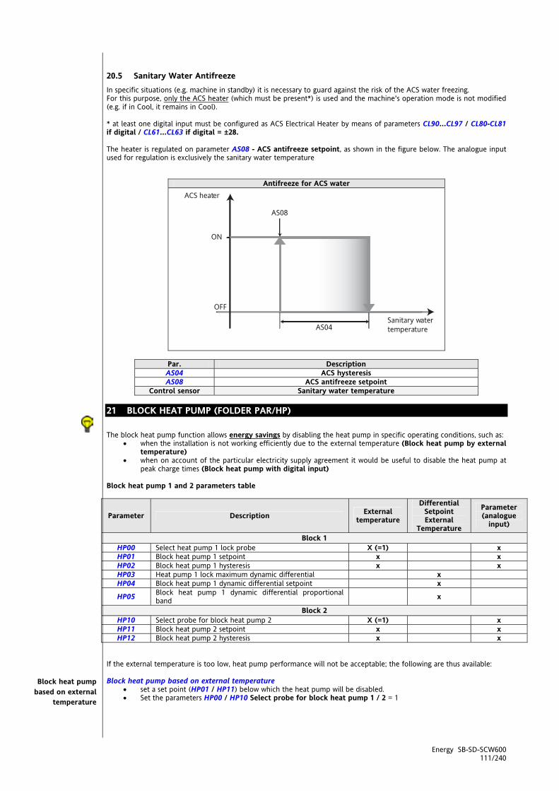
Energy SB-SD-SCW600 111/240
20.5 Sanitary Water Antifreeze In specific situations (e.g. machine in standby) it is necessary to guard against the risk of the ACS water freezing. For this purpose, only the ACS heater (which must be present*) is used and the machine's operation mode is not modified (e.g. if in Cool, it remains in Cool). * at least one digital input must be configured as ACS Electrical Heater by means of parameters CL90…CL97 / CL80-CL81 if digital / CL61…CL63 if digital = ±28. The heater is regulated on parameter AS08 - ACS antifreeze setpoint, as shown in the figure below. The analogue input used for regulation is exclusively the sanitary water temperature
Antifreeze for ACS water
Par. Description AS04 ACS hysteresis AS08 ACS antifreeze setpoint
Control sensor Sanitary water temperature 21 BLOCK HEAT PUMP (FOLDER PAR/HP) The block heat pump function allows energy savings by disabling the heat pump in specific operating conditions, such as:
when the installation is not working efficiently due to the external temperature (Block heat pump by external temperature)
when on account of the particular electricity supply agreement it would be useful to disable the heat pump at peak charge times (Block heat pump with digital input)
Block heat pump 1 and 2 parameters table
Parameter Description External temperature
Differential Setpoint External
Temperature
Parameter (analogue
input)
Block 1 HP00 Select heat pump 1 lock probe X (=1) x HP01 Block heat pump 1 setpoint x x HP02 Block heat pump 1 hysteresis x x HP03 Heat pump 1 lock maximum dynamic differential x HP04 Block heat pump 1 dynamic differential setpoint x
HP05 Block heat pump 1 dynamic differential proportional band x
Block 2 HP10 Select probe for block heat pump 2 X (=1) x HP11 Block heat pump 2 setpoint x x HP12 Block heat pump 2 hysteresis x x
If the external temperature is too low, heat pump performance will not be acceptable; the following are thus available: Block heat pump based on external temperature
set a set point (HP01 / HP11) below which the heat pump will be disabled. Set the parameters HP00 / HP10 Select probe for block heat pump 1 / 2 = 1
Block heat pump based on external
temperature
Sanitary water temperature
ACS heater
AS08
ON
OFF
AS04 IMG INFO

Energy SB-SD-SCW600 112/240
Block heat pump based on regulation temperature set a set point (HP01 / HP11) above which the heat pump will be disabled. Set the parameters HP00 / HP10 Select probe for block heat pump 1 / 2 > 1
Value Probe Mode
0 No probe (block pump disabled) - 1 External temperature Heating 2 Internal exchanger water/air inlet temperature Cooling 3 Internal exchanger water/air outlet temperature Cooling 4 Circuit 1 and 2 internal exchanger water outlet average temperature Cooling 5 Recovery exchanger inlet water temperature
(or external exchanger) Cooling
6 Recovery exchanger water outlet temperature (or external exchanger)
Cooling
7 Circuit 1 and 2 external exchanger average temperature Cooling Note: The Economy LED illuminates with a steady light on the display to indicate heat pump lock (set UI07 - Configuration of Economy LED = 2)
Block heat pump based on
regulation temperature

Energy SB-SD-SCW600 113/240
Block heat pump based on external temperature
Circuit 1 / Circuit 2 Block heat pump based on regulation temperature
Circuit 1 / Circuit 2
Heat Pump = pompa di calore Heat Pump = pompa di calore
Heat Pump Heat pump state T ext External temperature AIn Probe selected by parameter
21.1.1 Block heat pump 1 - setpoint It is useful to be able to vary the block heat pump temperature according to the external temperature. This regulator linearly compensates the setpoint for the block heat pump function with a positive or negative differential value according to the external temperature. The real setpoint for the block function is calculated by adding this dynamic differential to the value of parameter HP01 - Block heat pump 1 setpoint Enabling The regulator is enabled by setting parameter HP03 - Heat pump 1 lock maximum dynamic differential ≠ 0. Furthermore, an analogue input must be configured as external temperature.
Positive offset HP03>0 Negative offset HP03<0
Heat Pump = pompa di calore Heat Pump = pompa di calore
21.1.2 Block heat pump from digital input If a digital input is configured as “Block heat pump” or CL40..CL45 / CL50..CL54=±20 , then when it is activated, the heat pump will be deactivated.
<IMG INFO> 202,9 81,95 0 2 0,25 -83,25 -1
<IMG INFO> 209,9 78,35 0 2
IMG INFO
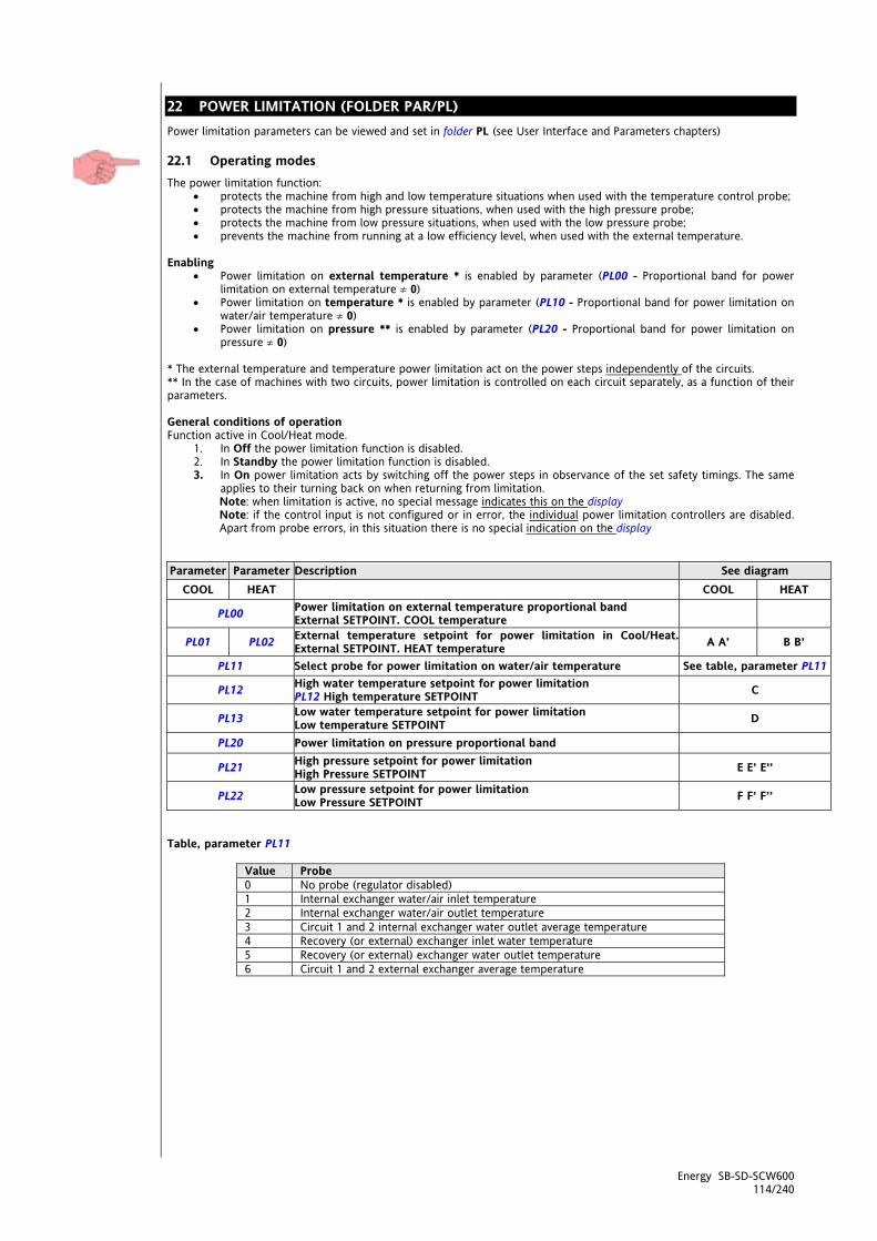
Energy SB-SD-SCW600 114/240
22 POWER LIMITATION (FOLDER PAR/PL) Power limitation parameters can be viewed and set in folder PL (see User Interface and Parameters chapters)
22.1 Operating modes The power limitation function:
protects the machine from high and low temperature situations when used with the temperature control probe; protects the machine from high pressure situations, when used with the high pressure probe; protects the machine from low pressure situations, when used with the low pressure probe; prevents the machine from running at a low efficiency level, when used with the external temperature.
Enabling
Power limitation on external temperature * is enabled by parameter (PL00 - Proportional band for power limitation on external temperature ≠ 0)
Power limitation on temperature * is enabled by parameter (PL10 - Proportional band for power limitation on water/air temperature ≠ 0)
Power limitation on pressure ** is enabled by parameter (PL20 - Proportional band for power limitation on pressure ≠ 0)
* The external temperature and temperature power limitation act on the power steps independently of the circuits. ** In the case of machines with two circuits, power limitation is controlled on each circuit separately, as a function of their parameters. General conditions of operation Function active in Cool/Heat mode.
1. In Off the power limitation function is disabled. 2. In Standby the power limitation function is disabled. 3. In On power limitation acts by switching off the power steps in observance of the set safety timings. The same
applies to their turning back on when returning from limitation. Note: when limitation is active, no special message indicates this on the display Note: if the control input is not configured or in error, the individual power limitation controllers are disabled. Apart from probe errors, in this situation there is no special indication on the display
Parameter Parameter Description See diagram
COOL HEAT COOL HEAT
PL00 Power limitation on external temperature proportional band External SETPOINT. COOL temperature
PL01 PL02 External temperature setpoint for power limitation in Cool/Heat.External SETPOINT. HEAT temperature A A’ B B’
PL11 Select probe for power limitation on water/air temperature See table, parameter PL11
PL12 High water temperature setpoint for power limitation PL12 High temperature SETPOINT C
PL13 Low water temperature setpoint for power limitation Low temperature SETPOINT D
PL20 Power limitation on pressure proportional band
PL21 High pressure setpoint for power limitation High Pressure SETPOINT E E’ E’’
PL22 Low pressure setpoint for power limitation Low Pressure SETPOINT F F’ F’’
Table, parameter PL11
Value Probe 0 No probe (regulator disabled) 1 Internal exchanger water/air inlet temperature 2 Internal exchanger water/air outlet temperature 3 Circuit 1 and 2 internal exchanger water outlet average temperature 4 Recovery (or external) exchanger inlet water temperature 5 Recovery (or external) exchanger water outlet temperature 6 Circuit 1 and 2 external exchanger average temperature

Energy SB-SD-SCW600 115/240
Power limitation - 2 compressors Diagrams A’ B’ E’ E’’ F’ F’’ represent the inhibition/enabling of two power steps (two compressor machine or power stage compressor); The pressure or temperature interval between inhibition/enabling of one step and the next depends on the proportional band and the number of resources present in the circuit. The switching on/off of steps respects the operating logic set Power limitation - 4 compressors The external temperature and temperature power limitation act on the power steps independently of the circuits.
22.2 Power limitation - by external temperature (Cool and Heat)
COOL HEAT Diagram A
for high external temperature PL01 = External SET POINT COOL temperature
Diagram B for low external temperature PL02 = External SET
POINT HEAT temperature Total of 4 steps
NOTE: “POWER REDUCTION” INDICATES THE POWER STEPS TO BE CUT OUT Diagram A Diagram B
Total of 2 steps
NOTE: “POWER REDUCTION” INDICATES THE POWER STEPS TO BE CUT OUT
PL00
PowerReduction
Ext. Temp
Step 4
Step 3
Step 2
Step 1
SET POINT Ext. Temp. HEAT
PL02
PL00
PowerReduction
Ext. Temp
Step 4
Step 3
SET POINT Ext. Temp. COOL
Step 2
Step 1
PL01
IMG INFO
PL00
PowerReduction
Ext. Temp
Step 2
Step 1
SET POINT Ext. Temp. HEAT
PL02
<IMG INFO>
PL00
PowerReduction
Ext. Temp
Step 2
Step 1
SET POINT Ext. Temp. COOL
PL01

Energy SB-SD-SCW600 116/240
22.3 Power limitation - by temperature (Cool and Heat) Example of power limitation on temperature in a 4 step machine,
Diagram C for high temperature on the control probe
(Cool and Heat) PL12 High temperature SETPOINT
Diagram D for low temperature on the control probe
(Cool and Heat) PL13 Low temperature SETPOINT
NOTE: “POWER REDUCTION” INDICATES THE POWER STEPS TO BE CUT OUT
PL10
PowerReduction
High temp.
Step 4
Step 3
SET POINT HIGH temp.
Step 2
Step 1
PL12
<IMG INFO> 209,6 174,25 0 2 -5,05
PL10
PowerRedcuction
Low. Temp
Step 4
Step 3
Step 2
Step 1
SET POINT Low. Temp
PL13
<IMG INFO> 214,2 167 05
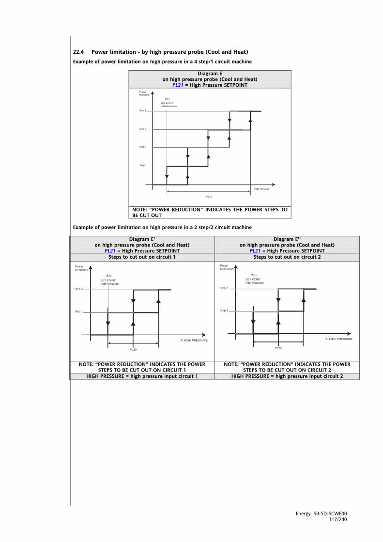
Energy SB-SD-SCW600 117/240
22.4 Power limitation - by high pressure probe (Cool and Heat) Example of power limitation on high pressure in a 4 step/1 circuit machine
Diagram E on high pressure probe (Cool and Heat)
PL21 = High Pressure SETPOINT
NOTE: “POWER REDUCTION” INDICATES THE POWER STEPS TO BE CUT OUT
Example of power limitation on high pressure in a 2 step/2 circuit machine
Diagram E' on high pressure probe (Cool and Heat)
PL21 = High Pressure SETPOINT
Diagram E'' on high pressure probe (Cool and Heat)
PL21 = High Pressure SETPOINT Steps to cut out on circuit 1 Steps to cut out on circuit 2
NOTE: “POWER REDUCTION” INDICATES THE POWER
STEPS TO BE CUT OUT ON CIRCUIT 1 NOTE: “POWER REDUCTION” INDICATES THE POWER
STEPS TO BE CUT OUT ON CIRCUIT 2 HIGH PRESSURE = high pressure input circuit 1 HIGH PRESSURE = high pressure input circuit 2
PL20
PowerReduction
High Pressure.
Step 4
Step 3
SET POINT HIGH Pressure
Step 2
Step 1
PL21
IMG INFO
PL20
PowerReduction
AI HIGH PRESSURE
Step 2
Step 1
SET POINT High Pressure
PL21
<IMG INFO> 214,6
PL20
PowerReduction
AI HIGH PRESSURE
Step 2
Step 1
SET POINT High Pressure
PL21
<IMG INFO> 214,2 144

Energy SB-SD-SCW600 118/240
22.5 Power limitation - by low pressure probe (Cool and Heat) Example of power limitation on low pressure in a 4 step/1 circuit machine
Diagram F on low pressure probe (Cool and Heat)
PL22 Low Pressure SETPOINT
NOTE: “POWER REDUCTION” INDICATES THE POWER STEPS TO BE CUT OUT
Example of power limitation on low pressure in a 2 step/2 circuit machine
Diagram F' on low pressure probe (Cool and Heat)
PL22 Low Pressure SETPOINT
Diagram F'' on low pressure probe (Cool and Heat)
PL22 Low Pressure SETPOINT
Steps to cut out on circuit 1 Steps to cut out on circuit 2
NOTE: “POWER REDUCTION” INDICATES THE POWER STEPS
TO BE CUT OUT ON CIRCUIT 1 NOTE: “POWER REDUCTION” INDICATES THE POWER STEPS
TO BE CUT OUT ON CIRCUIT 2 LOW PRESSURE = low pressure input circuit 1 LOW PRESSURE = low pressure input circuit 2
PL20
PowerReduction
Low Pressure
Step 4
Step 3
Step 2
Step 1
SET POINT Low Pressure
PL22
<IMG INFO>
PL20
PowerReduction
LOW PRESSURE
Step 2
Step 1
SET POINT Low Pressure
PL22
<IMG INFO> 222,7
PL20
PowerReduction
LOW PRESSURE
Step 2
Step 1
SET POINT Low Pressure
PL22
<IMG INFO> 222,15

Energy SB-SD-SCW600 119/240
22.6 Power limitation to 50% Function enabled by configuring: a digital input as 50% power limitation or by setting one of parameters CL40…CL45 = ±21 or an analogue input when configured as digital input CL46…CL54 = ±21; Activating the digital input halves the availability of power steps, thus reducing energy consumption. Power limitation to 50% is independent of the forced power stages described above. The limitations act in parallel, and the number of steps limited is the maximum of the two limitation functions. With the SB600 this results in a large number of possible situations: the first column shows the power steps normally available (without alarms or blocks, a value which depends exclusively on how the SB600 is configured, not on the particular situation at any given time), while the second column shows the residual power steps with 50% power limitation active. Number of power steps configured
Number of power steps available with limitation to 50% active Notes
1 1 No effect 2 1 3 2 4 2 By step we mean the power equivalent of a compressor power stage; the selection of the step is subordinate to the compressor controller mechanism (e.g. limitation to 50% makes no distinction between the power stages of different circuits). In other words, the selection of which power step to turn off is made by the power stage on/off logic described in the chapter Compressors. Example 1 SB device configured with two power steps, one per circuit (= one compressor per circuit): the activation of the input has no effect if only one compressor is running at the time; if the input stays active, it will affect any request for activation of the compressor of the other circuit (it will impede it). Example 2 SB device configured with four power steps (one power stage compressor per circuit): activation of the input has no effect if only 1 or 2 power stages are active at the time (whether both or only one compressor is running), as for the previous example. It will have an effect if 3 or 4 power stages are active and 1 or 2 steps are turned off according to the compressor controller logic (either both compressors or only one remains active). As fro other forms of limitation, the step off/on sequence is subordinate to the safety timings. The function has no effect on other resources, and is not indicated on the display in any way.
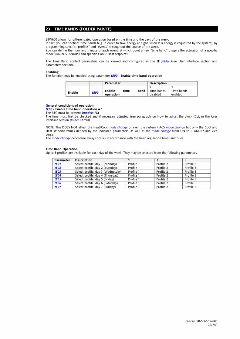
Energy SB-SD-SCW600 120/240
23 TIME BANDS (FOLDER PAR/TE) SBW600 allows for differentiated operation based on the time and the days of the week. In fact, you can “define” time bands (e.g. in order to save energy at night, when less energy is requested by the system), by programming specific “profiles” and “events” throughout the course of the week. You can define the hour and minute of each event, at which point a new “time band” triggers the activation of a specific mode (ON or STANDBY) and specific Cool / Heat setpoints. The Time Band control parameters can be viewed and configured in the tE folder (see User interface section and Parameters section). Enabling The function may be enabled using parameter tE00 - Enable time band operation
Parameter Description 0 1
Enable tE00 Enable time band operation
Time bands disabled
Time bands enabled
General conditions of operation tE00 - Enable time band operation = 1 The RTC must be present (models /C) The time must first be checked and if necessary adjusted (see paragraph on How to adjust the clock (CL), in the User Interface section (folder PAr/UI) NOTE: This DOES NOT affect the Heat/Cool mode change or even the system / ACS mode change but only the Cool and Heat setpoint values defined by the indicated parameters, as well as the mode change from ON to STANDBY and vice versa. The mode change procedure always occurs in accordance with the basic regulation times and rules. Time Band Operation Up to 3 profiles are available for each day of the week. They may be selected from the following parameters:
Parameter Description 1 2 3 tE01 Select profile, day 1 (Monday) Profile 1 Profile 2 Profile 3 tE02 Select profile, day 2 (Tuesday) Profile 1 Profile 2 Profile 3 tE03 Select profile, day 3 (Wednesday) Profile 1 Profile 2 Profile 3 tE04 Select profile, day 4 (Thursday) Profile 1 Profile 2 Profile 3 tE05 Select profile, day 5 (Friday) Profile 1 Profile 2 Profile 3 tE06 Select profile, day 6 (Saturday) Profile 1 Profile 2 Profile 3 tE07 Select profile, day 7 (Sunday) Profile 1 Profile 2 Profile 3
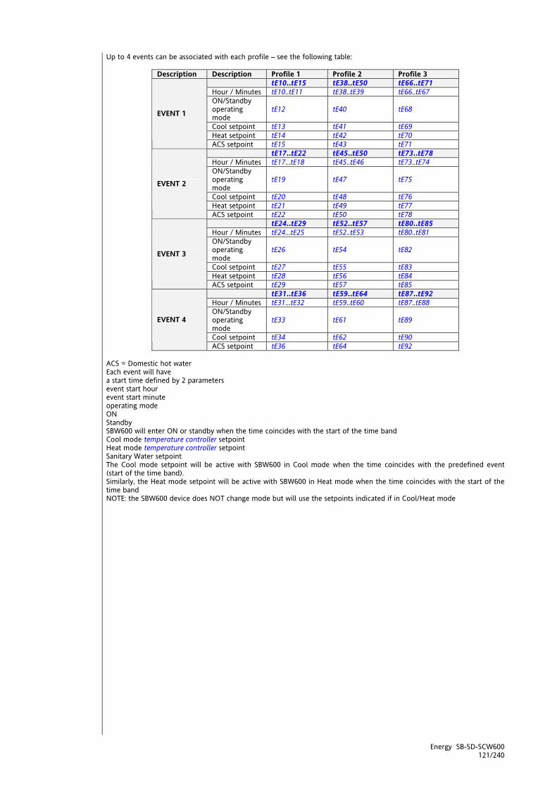
Energy SB-SD-SCW600 121/240
Up to 4 events can be associated with each profile – see the following table:
Description Description Profile 1 Profile 2 Profile 3 tE10..tE15 tE38..tE50 tE66..tE71 Hour / Minutes tE10..tE11 tE38..tE39 tE66..tE67 ON/Standby operating mode
tE12 tE40 tE68
Cool setpoint tE13 tE41 tE69 Heat setpoint tE14 tE42 tE70
EVENT 1
ACS setpoint tE15 tE43 tE71 tE17..tE22 tE45..tE50 tE73..tE78 Hour / Minutes tE17...tE18 tE45..tE46 tE73..tE74 ON/Standby operating mode
tE19 tE47 tE75
Cool setpoint tE20 tE48 tE76 Heat setpoint tE21 tE49 tE77
EVENT 2
ACS setpoint tE22 tE50 tE78 tE24..tE29 tE52..tE57 tE80..tE85 Hour / Minutes tE24...tE25 tE52..tE53 tE80..tE81 ON/Standby operating mode
tE26 tE54 tE82
Cool setpoint tE27 tE55 tE83 Heat setpoint tE28 tE56 tE84
EVENT 3
ACS setpoint tE29 tE57 tE85 tE31..tE36 tE59..tE64 tE87..tE92 Hour / Minutes tE31...tE32 tE59..tE60 tE87..tE88 ON/Standby operating mode
tE33 tE61 tE89
Cool setpoint tE34 tE62 tE90
EVENT 4
ACS setpoint tE36 tE64 tE92 ACS = Domestic hot water Each event will have a start time defined by 2 parameters event start hour event start minute operating mode ON Standby SBW600 will enter ON or standby when the time coincides with the start of the time band Cool mode temperature controller setpoint Heat mode temperature controller setpoint Sanitary Water setpoint The Cool mode setpoint will be active with SBW600 in Cool mode when the time coincides with the predefined event (start of the time band). Similarly, the Heat mode setpoint will be active with SBW600 in Heat mode when the time coincides with the start of the time band NOTE: the SBW600 device does NOT change mode but will use the setpoints indicated if in Cool/Heat mode

<IMG INFO> 42,7 29,75 1 2 51 -28 35
24 ALARMS AND DIAGNOSTICS (FOLDER PAR/AL) The “Energy SBW600 ” performs full installation diagnostics and reports a variety of alarms. Parameters for alarm activation and acknowledgment can be viewed and configured in folder AL (parameters AL00…AL82) (see User Interface and Parameters chapters) Automatic reset For automatic reset alarms, normal operation is restored as soon as the cause of the alarm has been removed. Manual reset Alarms can be manually reset by pressing and releasing the [UP + DOWN] keys Normal operation can only be reset
by pressing a key on the instrument keyboard and only if the cause of the alarm has been removed.
Alarm acknowledgement Alarms can be acknowledged by pressing any key. NOTE: acknowledging an alarm has no effect on the alarm other than on the alarm LED that goes from fixed to flashing. An alarm has two effects:
It blocks the utilities concerned Message on keyboard display alternates with a message on the main display
The next two sections summarize alarms grouped by type (digital or analogue). Alarm code and alarm parameters are in bold (PAr/AL folder) For some alarms, the signal can be excluded for a preset interval, set in the relative parameter. No. interventions The number of interventions per sampling period is defined in parameter AL00 - Time interval for alarm event count For some alarms, the number of interventions can be counted: if, in a period of time defined in AL00 a threshold set in a parameter is exceeded, the alarm changes from automatic to manual reset. Alarms are counted every AL00/32 (minutes) = sample time. AL00 and hence also AL00/32 is expressed in minutes. Example: AL10-High pressure alarm circuit 1: if the number of events per hour is set to AL10, for the alarm to change from automatic to manual reset, the count must reach the number set in AL10. Example AL10=3
Event =Nr. Events A: Automatic reset Sampling: sampling AL00/32 sampling time 1 M: Manual reset Time: time 2 Alarm: alarm 3 (=AL10)
NOTE:
if, during the sample time AL10/32 several alarm events of the same type occur (e.g. High pressure alarm circuit 1) only 1 event is counted
if the alarm conditions is active for several sample times, only 1 event is counted. if the alarm event is active for a period greater than AL00 the counter resets to zero
Alarms
Automatic reset
Manual reset
No. interventions

24.1.1 Digital alarms
Alarm code Name of alarm Bypass
activation event Bypass time
Automatic alarm
activation time
Manual alarm
activation time
Exit alarm deactivation
time
Number of interventions
per sample time
Er01 High pressure alarm circuit 1 None not
present not present not present not present AL10
Er02 High pressure alarm circuit 2 None not
present not present not present not present AL10
Er05 Low pressure alarm circuit 1
Circuit compressor activated or
reversal of 4-way valve (NOTE 1)
AL11 not present not present not present AL12
Er06 Low pressure alarm circuit 2
Circuit compressor activated or
reversal of 4-way valve (NOTE 1)
AL11 not present not present not present AL12
Er20 (NOTE 2)
Internal circuit flow meter alarm
Internal circuit pump activation (One of the two
pumps)
AL14 AL15 AL16 AL15 not present
Er25 (NOTE 3)
External flow switch alarm
External circuit pump activation AL17 AL18 AL19 AL18 not present
Er10 Compressor 1 thermal switch
Compressor 1 switched on AL20 not present not present not present AL21
Er11 Compressor 2 thermal switch
Compressor 2 switched on AL20 not present not present not present AL21
Er12 Compressor 3 thermal switch
Compressor 3 switched on AL20 not present not present not present AL21
Er13 Compressor 4 thermal switch
Compressor 4 switched on AL20 not present not present not present AL21
Er15 (NOTE 2)
Compressor 1 oil pressure switch
Compressor 1 switched on AL22 Not present not present Not present AL23
Er16 (NOTE 2)
Compressor 2 oil pressure switch
Compressor 2 switched on AL22 Not present not present Not present AL23
Er17 (NOTE 2)
Compressor 3 oil pressure switch
Compressor 3 switched on AL22 Not present not present Not present AL23
Er18 (NOTE 2)
Compressor 4 oil pressure switch
Compressor 4 switched on AL22 Not present not present Not present AL23
Er40 Internal
exchanger fan thermal switch
None Not present Not present not present Not present AL24
Er41 External
exchanger fan thermal switch
circuit 1
None Not present Not present not present Not present AL25
Er42 External
exchanger fan thermal switch
circuit 2
None Not present Not present not present Not present AL25
Er21 Internal circuit
pump 1 thermal switch
None Not present Not present not present Not present AL26
Er22 Internal circuit
pump 2 thermal switch
None Not present Not present not present Not present AL26
Er26 External circuit pump thermal
switch None Not
present Not present not present Not present AL27
Er50 Internal
exchanger electric heater thermal switch
None Not present Not present not present Not present not present
Er51 Internal
exchanger electric heaters 2 thermal switch
None Not present Not present not present Not present not present
Er56 Auxiliary output alarm None Not
present Not present not present Not present not present
(NOTE 1) The bypass is activated by the reversal of the 4-way valve only if at least one compressor is on (NOTE 2) The alarm is active only if the associated resource (e.g. a given compressor or pump) is active (NOTE 3) The alarm is active only if the associated resource (e.g. a given compressor or pump) is active and in heating mode only
Digital alarms
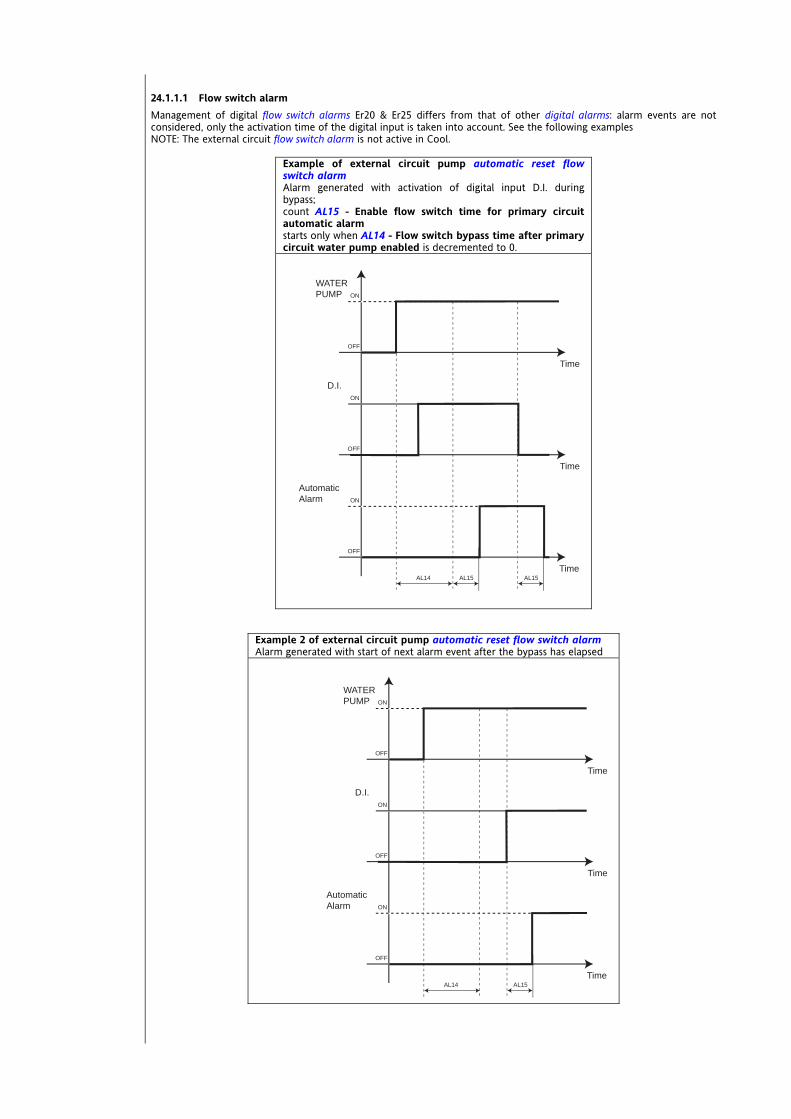
24.1.1.1 Flow switch alarm Management of digital flow switch alarms Er20 & Er25 differs from that of other digital alarms: alarm events are not considered, only the activation time of the digital input is taken into account. See the following examples NOTE: The external circuit flow switch alarm is not active in Cool.
Example of external circuit pump automatic reset flow switch alarm Alarm generated with activation of digital input D.I. during bypass; count AL15 - Enable flow switch time for primary circuit automatic alarm starts only when AL14 - Flow switch bypass time after primary circuit water pump enabled is decremented to 0.
Example 2 of external circuit pump automatic reset flow switch alarm Alarm generated with start of next alarm event after the bypass has elapsed
AL15AL14
ON
OFF
Time
WATERPUMP
ON
OFF
Time
D.I.
ON
OFF
TimeAL15
Automatic Alarm
<IMG INFO>
AL14
ON
OFF
Time
WATERPUMP
ON
OFF
Time
D.I.
ON
OFF
TimeAL15
Automatic Alarm
<IMG INFO>

Example of external circuit pump manual reset flow switch alarm AL15 - Enable flow switch time for primary circuit automatic alarm AL16 - Enable flow switch time for primary circuit manual alarm
AL15
ON
OFF
Time
D.I
ON
OFF
Time
ON
OFF
TimeAL16
Automatic Alarm
ManualAlarm
<IMG INFO>

Energy SB-SD-SCW600 126/240
24.1.2 Analogue alarms NOTES (NOTE 1) if N° interventions per hour = 1, the alarm is always of the manual reset type. (NOTE 2) Alarm bypass is active in heating mode only.
Er03 High pressure (analogue) circuit 1 None None AL40 AL41 Not present AL42 High pressure probe circuit
1
Er04 High pressure (analogue) circuit 2 None None AL40 AL41 Not present AL42 High pressure probe circuit
2
Er07 Low pressure (analogue) circuit 1
A circuit 1 compressor switched on or reversal
of the 4-way valve AL43 Al44 AL45 Not present AL46 Low pressure probe circuit
1
Er08 Low pressure (analogue) circuit 2
A circuit 2 compressor Switched on or reversal
of the 4-way valve AL43 Al44 AL45 Not present AL46 Low pressure probe circuit
2
Er30 Internal circuit antifreeze
On/Off (local or remote), input in heat
mode (NOTE 2)
AL50 AL51 AL52 Not present A53 Internal exchanger
water/air outlet temperature
Er31 External circuit antifreeze
On/Off (local or remote), input in heat
mode (NOTE 2)
AL54 AL55 AL56 Not present A57 External exchanger outlet water temperature
Er35 High temperature None None AL47 AL48 AL49 Automatic reset
Internal exchanger water/air outlet
temperature
Analogue alarms
Alarm code Name of alarm Bypass activation
event Bypass time SET activation Hysteresis
Automatic alarm time (NOTE 1)
No. interventions
Control sensor

Energy SB-SD-SCW600 127/240
24.1.3 Table of Alarms
The alarm signal consists of a code, the format being “Ernn” (nn is a 2-figure number identifying the type of alarm, e.g. Er00, Er25, Er39….). When more than one alarm occurs at the same time, the one with the lowest number will be shown first; e.g. simultaneous alarms Er00 and Er01. Er00 will be shown alternating
between the display and the main screen If the measurement on the main display is incorrect, in the event of an alarm, the alarm code will alternate with “----“.
All possible alarms are listed in the table below with their respective codes and the relative utilities blocked:
column Alarm code
NOTE: codes are listed in increasing order (Er00, Er01) and some numbers are “skipped” (Er06 does not exist)
Name of alarm
CMP 1/2 Compressor 1/power step 2 notes PUMP 1/2 Pump 1/2
D digital A analogue
alarm
See digital alarms table Reset AUTO automatic
OFF COMP1 OFF compressor 1 OFF COMP2 OFF compressor 2 OFF COMP3 OFF compressor 3 OFF COMP4 OFF compressor 4 OFF (1) When used for temperature control OFF (2) When used for temperature control and/or
antifreeze OFF RES1 OFF heater 1
UTILITY
OFF RES2 OFF heater 2 Table of Alarms
Alar
m c
ode
Nam
e of
ala
rm
Not
es
Dig
ital/A
nalo
gue
Alar
m t
ype
SAN
ITAR
Y W
ATER
VA
LVE
SAN
ITAR
Y W
ATER
H
EATE
R
COM
PRES
SORS
EXTE
RNAL
EX
CHAN
GER
FAN
RECI
RCU
LATI
ON
FAN
INTE
RNAL
CIR
CUIT
PU
MP
EXTE
RNAL
CIR
CUIT
PU
MP
INTE
RNAL
EX
CHAN
GER
H
EATE
RS
EXTE
RNAL
EX
CHAN
GER
H
EATE
RS
OU
TPU
T AU
XILI
ARY
BOIL
ER
Er00 General alarm D AUTO OFF0 OFF OFF OFF OFF OFF OFF OFF OFF OFF OFF Er01 High pressure (digital) circuit 1 D Events OFF (1) Er02 High pressure (digital) circuit 2 D Events OFF (1) Er03 High pressure (analogue) circuit 1 A Events OFF (1)
Alarm table key
Table of Alarms

Energy SB-SD-SCW600 128/240
Alar
m c
ode
Nam
e of
ala
rm
Not
es
Dig
ital/A
nalo
gue
Alar
m t
ype
SAN
ITAR
Y W
ATER
VA
LVE
SAN
ITAR
Y W
ATER
H
EATE
R
COM
PRES
SORS
EXTE
RNAL
EX
CHAN
GER
FAN
RECI
RCU
LATI
ON
FAN
INTE
RNAL
CIR
CUIT
PU
MP
EXTE
RNAL
CIR
CUIT
PU
MP
INTE
RNAL
EX
CHAN
GER
H
EATE
RS
EXTE
RNAL
EX
CHAN
GER
H
EATE
RS
OU
TPU
T AU
XILI
ARY
BOIL
ER
Er04 High pressure (analogue) circuit 2 A Events OFF (1) Er05 Low pressure (digital) D Events OFF (1) OFF (2) OFF Er07 Low pressure (analogue) circuit 1 A Events OFF (1) OFF (2) OFF Er08 Low pressure (analogue) circuit 2 A Events OFF (1) OFF (2) OFF Er09 No refrigerant A Events OFF OFF (2) OFF
Er10 Compressor 1 thermal switch CMP 1 D Events OFF COMP1
Er11 Compressor 2 thermal switch CMP 2 D Events OFF COMP2
Er12 Compressor 3 thermal switch CMP 3 D Events OFF COMP3
Er13 Compressor 4 thermal switch CMP 4 D Events OFF COMP4
Er15 Compressor 1 oil pressure switch CMP 1 D Events OFF COMP1
Er16 Compressor 2 oil pressure switch CMP 2 D Events OFF COMP2
Er17 Compressor 3 oil pressure switch CMP 3 D Events OFF COMP3
Er18 Compressor 4 oil pressure switch CMP 4 D Events OFF COMP4
Er20 Primary circuit flow switch D Time
OFF for manual
reset alarm
OFF OFF
OFF for manual
reset alarm
OFF OFF
Er21 Internal circuit pump 1 thermal switch Pump 1 D Events OFF (3) OFF (3) OFF Pump 1 OFF (3) OFF (3)
Er22 Internal circuit pump 2 thermal switch Pump 2 D Events OFF (3) OFF (3) OFF Pump 2 OFF (3) OFF (3)
Er25 External circuit flow switch D Time OFF
OFF for manual
reset alarm
OFF for manual
reset alarm
OFF
Er26 External circuit pump thermal switch D Events OFF OFF OFF Er30 Internal circuit antifreeze A AUTO OFF OFF Er31 External circuit antifreeze A AUTO OFF OFF Er35 High temperature A AUTO OFF

Energy SB-SD-SCW600 129/240
Alar
m c
ode
Nam
e of
ala
rm
Not
es
Dig
ital/A
nalo
gue
Alar
m t
ype
SAN
ITAR
Y W
ATER
VA
LVE
SAN
ITAR
Y W
ATER
H
EATE
R
COM
PRES
SORS
EXTE
RNAL
EX
CHAN
GER
FAN
RECI
RCU
LATI
ON
FAN
INTE
RNAL
CIR
CUIT
PU
MP
EXTE
RNAL
CIR
CUIT
PU
MP
INTE
RNAL
EX
CHAN
GER
H
EATE
RS
EXTE
RNAL
EX
CHAN
GER
H
EATE
RS
OU
TPU
T AU
XILI
ARY
BOIL
ER
Er40 Internal exchanger fan thermal switch D Events OFF OFF OFF
Er41 External exchanger fan thermal switch circuit 1 D Events OFF (2) OFF (1) OFF (2)
Er42 External exchanger fan thermal switch circuit 2 D Events OFF (2) OFF (1) OFF (2)
Er45 Error clock faulty AUTO Er46 Error set clock AUTO Er47 LAN communication error AUTO
Er48 Anti-Legionnaire AUTO
Er50 Internal exchanger electric heater 1 thermal switch D AUTO OFF
RES.1
Er51 Internal exchanger electric heater 2 thermal switch D AUTO OFF
RES.1
Er56 Auxiliary output thermal switch D AUTO OFF
Er60 Internal exchanger water/air inlet temperature probe faulty AUTO See probe error table
Er61
Internal exchanger water/air outlet temperature probe faulty, or
Circuit 1 internal exchanger water outlet temperature probe faulty, or
Circuit 2 internal exchanger water outlet temperature probe faulty
AUTO See probe error table
Er62 Circuit 1 external exchanger temperature probe faulty, or Circuit 2 external exchanger temperature probe faulty AUTO See probe error table
Er63 External exchanger inlet water temperature probe faulty
AUTO See probe error table
Er64 External exchanger outlet water temperature probe faulty
AUTO See probe error table
Er66 Sanitary water temperature probe faulty
AUTO See Probe Errors Table
Er67 Display probe (temperature / pressure) faulty AUTO See probe error table
Er68 External temperature probe faulty AUTO
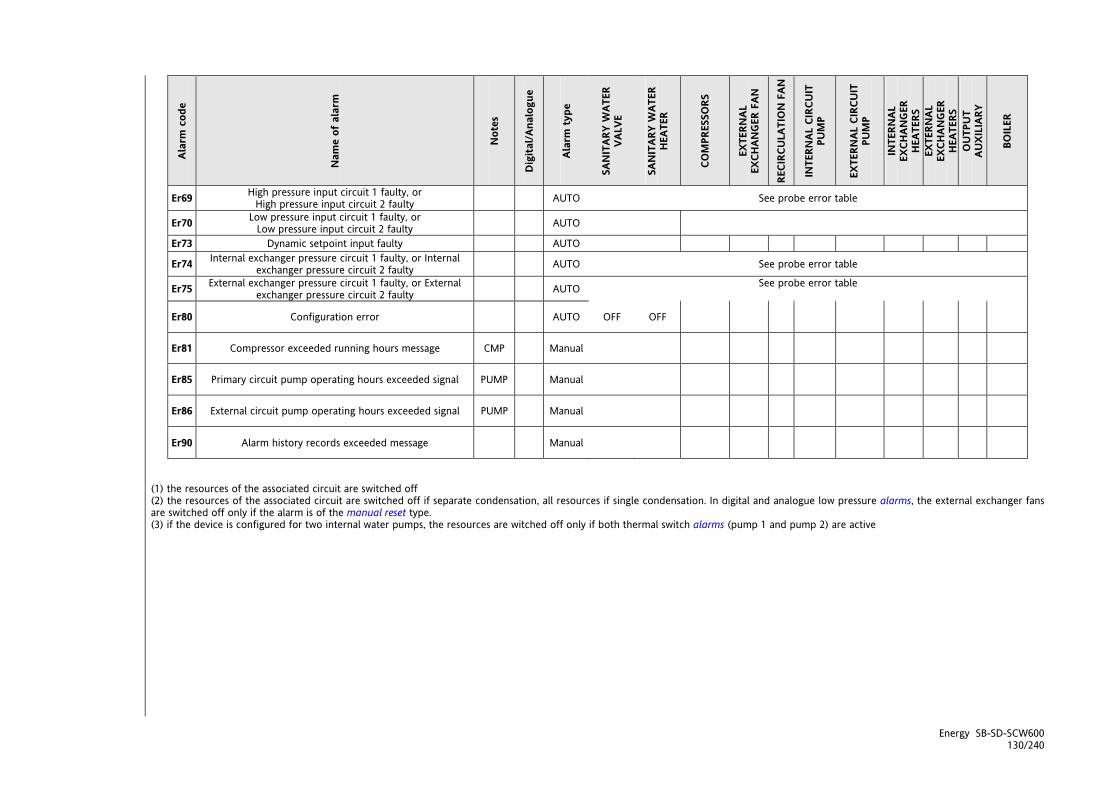
Energy SB-SD-SCW600 130/240
Alar
m c
ode
Nam
e of
ala
rm
Not
es
Dig
ital/A
nalo
gue
Alar
m t
ype
SAN
ITAR
Y W
ATER
VA
LVE
SAN
ITAR
Y W
ATER
H
EATE
R
COM
PRES
SORS
EXTE
RNAL
EX
CHAN
GER
FAN
RECI
RCU
LATI
ON
FAN
INTE
RNAL
CIR
CUIT
PU
MP
EXTE
RNAL
CIR
CUIT
PU
MP
INTE
RNAL
EX
CHAN
GER
H
EATE
RS
EXTE
RNAL
EX
CHAN
GER
H
EATE
RS
OU
TPU
T AU
XILI
ARY
BOIL
ER
Er69 High pressure input circuit 1 faulty, or High pressure input circuit 2 faulty AUTO See probe error table
Er70 Low pressure input circuit 1 faulty, or Low pressure input circuit 2 faulty AUTO
Er73 Dynamic setpoint input faulty AUTO
Er74 Internal exchanger pressure circuit 1 faulty, or Internal exchanger pressure circuit 2 faulty AUTO See probe error table
Er75 External exchanger pressure circuit 1 faulty, or External exchanger pressure circuit 2 faulty AUTO See probe error table
Er80 Configuration error AUTO OFF OFF
Er81 Compressor exceeded running hours message CMP Manual
Er85 Primary circuit pump operating hours exceeded signal PUMP Manual
Er86 External circuit pump operating hours exceeded signal PUMP Manual
Er90 Alarm history records exceeded message Manual
(1) the resources of the associated circuit are switched off (2) the resources of the associated circuit are switched off if separate condensation, all resources if single condensation. In digital and analogue low pressure alarms, the external exchanger fans are switched off only if the alarm is of the manual reset type. (3) if the device is configured for two internal water pumps, the resources are witched off only if both thermal switch alarms (pump 1 and pump 2) are active
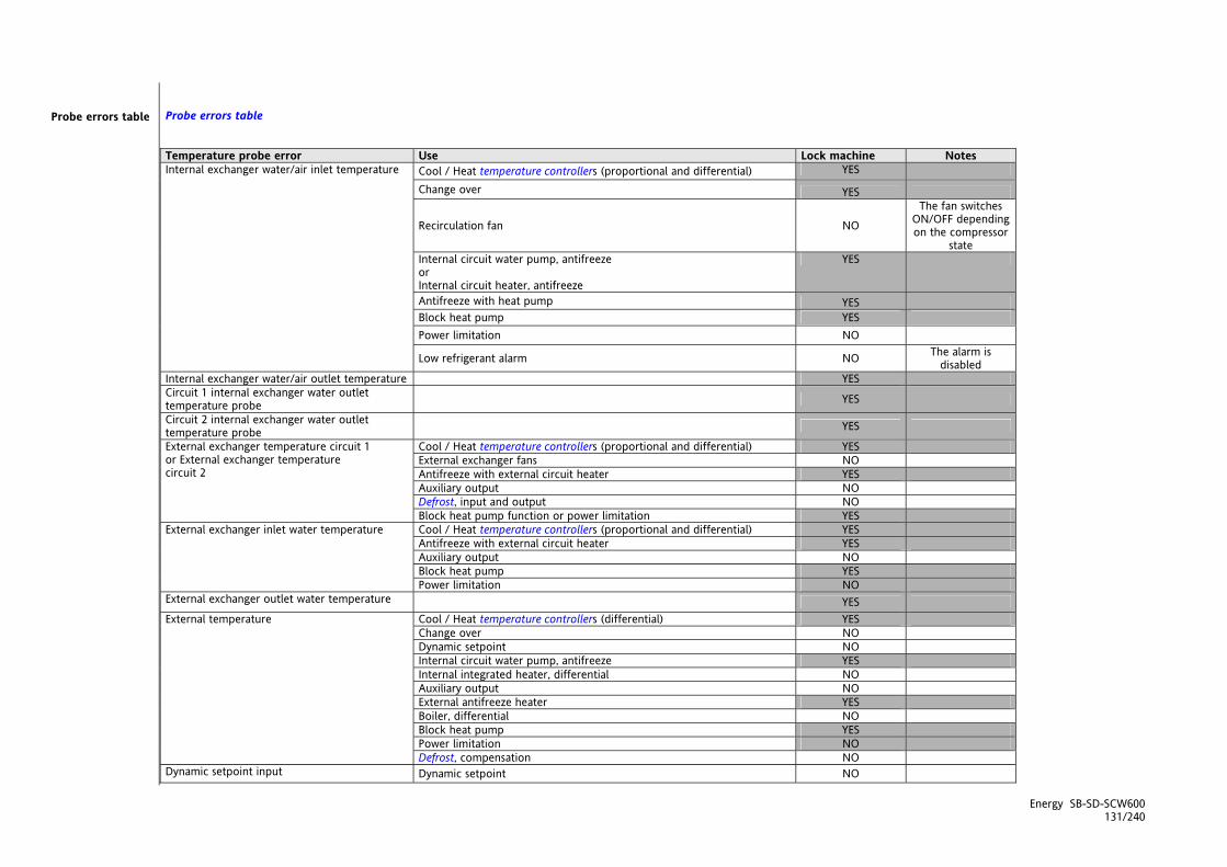
Energy SB-SD-SCW600 131/240
Probe errors table Temperature probe error Use Lock machine Notes
Cool / Heat temperature controllers (proportional and differential) YES
Change over YES
Recirculation fan NO
The fan switches ON/OFF depending on the compressor
state Internal circuit water pump, antifreeze or Internal circuit heater, antifreeze
YES
Antifreeze with heat pump YES Block heat pump YES Power limitation NO
Internal exchanger water/air inlet temperature
Low refrigerant alarm NO The alarm is disabled
Internal exchanger water/air outlet temperature YES Circuit 1 internal exchanger water outlet temperature probe
YES
Circuit 2 internal exchanger water outlet temperature probe
YES
Cool / Heat temperature controllers (proportional and differential) YES External exchanger fans NO Antifreeze with external circuit heater YES Auxiliary output NO Defrost, input and output NO
External exchanger temperature circuit 1 or External exchanger temperature circuit 2
Block heat pump function or power limitation YES Cool / Heat temperature controllers (proportional and differential) YES Antifreeze with external circuit heater YES Auxiliary output NO Block heat pump YES
External exchanger inlet water temperature
Power limitation NO External exchanger outlet water temperature YES
Cool / Heat temperature controllers (differential) YES Change over NO Dynamic setpoint NO Internal circuit water pump, antifreeze YES Internal integrated heater, differential NO Auxiliary output NO External antifreeze heater YES Boiler, differential NO Block heat pump YES Power limitation NO
External temperature
Defrost, compensation NO Dynamic setpoint input Dynamic setpoint NO
Probe errors table
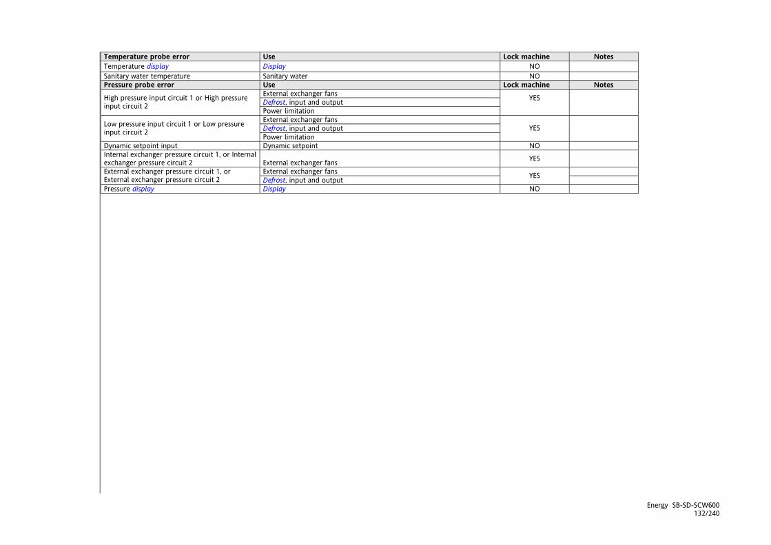
Energy SB-SD-SCW600 132/240
Temperature probe error Use Lock machine Notes Temperature display Display NO Sanitary water temperature Sanitary water NO Pressure probe error Use Lock machine Notes
External exchanger fans Defrost, input and output High pressure input circuit 1 or High pressure
input circuit 2 Power limitation
YES
External exchanger fans Defrost, input and output Low pressure input circuit 1 or Low pressure
input circuit 2 Power limitation YES
Dynamic setpoint input Dynamic setpoint NO Internal exchanger pressure circuit 1, or Internal exchanger pressure circuit 2 External exchanger fans YES
External exchanger fans External exchanger pressure circuit 1, or External exchanger pressure circuit 2 Defrost, input and output YES Pressure display Display NO

Energy SB-SD-SCW600 133/240

25 PARAMETERS (PAR) The Energy SBW600 is fully configurable via parameter settings; They can be modified with:
The Multi Function key (MFK) Keys on the SBW600 front panel / SKW22(L) remote panel PC and DeviceManager software
The following sections analyse each parameter, divided into categories (folders), in detail. Each folder is designated with a 2 character label (example: CF, UI, etc).
Folder label Acronym meaning (label) Parameters of:
CL Configuration Local Local I/O configuration Cr Configuration Remote terminal Remote terminal I/O configuration CF ConFiguration Configuration Ui User interface User interface tr thermoregulation Heat regulation St Statuses (Operating modes) Operating states CP ComPressors Compressor Pump PI Pump (Internal) Internal circuit water pump
FI Fan (Internal) Recirculation fans (internal) Fan FE Fan (External) External exchanger fans (external) Pump PE Pump (External) External exchanger pump
HI Electric Heaters (Internal) Internal exchanger electric heaters HE Electric Heaters (External) External exchanger electric heaters Electric heaters HA Auxiliary Output Auxiliary output
br boiler Boiler dF deFrost Defrost dS dynamic Setpoint Dynamic setpoint Ad Adaptive Adaptive (adaptive function) AF AntiFreeze Antifreeze
AS Sanitary Water Anti-Legionnaire's Disease
HP Heat Pump Block heat pump PL Power Limitation Power limitation tE Time Events Time Band AL ALarm Alarms Visibility and value of Parameters The Energy SBW600 is a family of controllers. There are 4+1 hardware models (see Appendix, Models section) with varying numbers of inputs and outputs. The 4+1 hardware models are divided into 3 DeviceManager models (version with 1 or 2 TRIAC and version with 5 relays). Depending on the model, some configuration parameters may not (usually) be visible or significant given that the associated resource is not present. See the table below:
TCL1 TCE1
TCL2 TCE2
DOL6 DOE6
Device Manager hardware
636 636
CL73-CL76-CL79 CE73-CE76-CE79
CL75-CL78-CL81 (AOL2)
CE75-CE78-CE81 (AOE2)
646 646/C 646/C/S
CL73-CL76-CL79 CE73-CE76-CE79 // m
odel
655 655/C
655/C/S
// // CL95 CE95
When not indicated otherwise, the parameter is always visible and modifiable, unless customised settings have been configured via serial NB: parameters and folder visibility can both be controlled (See Folder table). If folder visibility is modified, the new setting will apply to all parameters in the folder.

25.1.1 Local I/O configuration parameters (CL) - Configuration Local AiL1 analogue input type Configures the analogue input AiL1 - see table
0 Probe not configured 1 DI 2 NTC
AiL2 analogue input type Configures the analogue input AiL2 - as for CL00 AiL3 analogue input type Configures the analogue input AiL3 - see table
0 Probe not configured 3 4..20mA 1 DI 4 0-10V 2 NTC 5 0-5V 6 0-1V
AiL4 analogue input type Configures the analogue input AiL4 - as for CL02 AiL5 analogue input type Configures the analogue input AiL5 - as for CL00 AiL3 analogue input fullscale value Configures the full scale value with analogue input AiL3 AiL3 analogue input start of scale value Configures the start of scale value with analogue input AiL3 AiL4 analogue input fullscale value Configures the full scale value with analogue input AiL4 AiL4 analogue input start of scale value Configure the start of scale value with analogue input AiL4 AiL1 analogue input differential Configures the differential in analogue input AiL1 M.U. : °C AiL2 analogue input differential Configures the differential in analogue input AiL2 M.U. : °C AiL3 analogue input differential Configures the differential in analogue input AiL3 M.U. : °C / bar AiL4 analogue input differential Configures the differential in analogue input AiL4 M.U. : °C / bar AiL5 analogue input differential Configures the differential in analogue input AiL5 U.M. : °C Configuration of analogue input AiL1 Configures the analogue input AiL1 - see table
0 input disabled 1 Air/water inlet temperature
internal exchanger 2 Water/air outlet temperature
internal exchanger 3 Outlet water temperature
internal exchanger circuit 1 4 Outlet water temperature
internal exchanger circuit 2 5 External exchanger temperature circuit 1 6 External exchanger temperature circuit 2 7 Inlet water temperature
recovery (or external) exchanger 8 Outlet water temperature
recovery (or external) exchanger 9 External temperature 10 NOT USED 11 Sanitary water temperature 12 NOT USED 13 NOT USED 14 NOT USED 15 NOT USED 16 Temperature display
CL00
CL01
CL02
CL03
CL04
CL10
CL11
CL12
CL13
CL20
CL21
CL22
CL23
CL24
CL30

Configuration of analogue input AiL2 Configures the analogue input AiL2 - as for CL30 Configuration of analogue input AiL3 Configures the analogue input AiL3 - see table
0 input disabled 16 Temperature display 1 Air/water inlet temperature
internal exchanger 17 NOT USED
2 Water/air outlet temperature internal exchanger
18 NOT USED
3 Outlet water temperature internal exchanger circuit 1
19 NOT USED
4 Outlet water temperature internal exchanger circuit 2
20 NOT USED
5 External exchanger temperature circuit 1 21 High pressure input circuit 1 6 External exchanger temperature circuit 2 22 High pressure input circuit 2 7 Inlet water temperature
recovery (or external) exchanger 23 Low pressure input circuit 1
8 Outlet water temperature recovery (or external) exchanger
24 Low pressure input circuit 2
9 External temperature 25 Dynamic setpoint input 10 NOT USED 26 Internal exchanger pressure circuit 1 11 Sanitary water temperature 27 Internal exchanger pressure circuit 2 12 NOT USED 28 External exchanger pressure circuit 1 13 NOT USED 29 External exchanger pressure circuit 2 14 NOT USED 30 Pressure display 15 NOT USED
Configuration of analogue input AiL4 - as for CL32 Configuration of analogue input AiL5 - as for CL32 Configuration of digital input DI1 Configures the digital input DI1 - see table
0 Input disabled ±31 High pressure switch C2 ±1 Remote STD-BY ±32 Low pressure switch C1 ±2 Remote OFF ±33 Low pressure switch C2 ±3 Remote Summer/Winter ±34 Compressor 1 oil pressure switch ±4 Power step 1 request ±35 Compressor 2 oil pressure switch ±5 Power step 2 request ±36 Compressor 3 oil pressure switch ±6 Power step 3 request ±37 Compressor 4 oil pressure switch ±7 Power step 4 request ±38 NOT USED ±8 Heat power step 1 request digital input ±39 External exchanger fan thermal switch C1 ±9 Heat power step 2 request digital input ±40 External exchanger fan thermal switch C2 ±10 Heat power step 3 request digital input ±41 Internal exchanger fan thermal switch ±11 Heat power step 4 request digital input ±42 External Free-Cooling fan thermal switch ±12 Cool power step 1 request digital input ±43 Compressor 1 thermal switch ±13 Cool power step 2 request digital input ±44 Compressor 2 thermal switch ±14 Cool power step 3 request digital input ±45 Compressor 3 thermal switch ±15 Cool power step 4 request digital input ±46 Compressor 4 thermal switch ±16 Block compressor 1 ±47 Internal circuit pump 1 thermal switch ±17 Block compressor 2 ±48 Internal circuit pump 2 thermal switch ±18 Block compressor 3 ±49 External circuit pump thermal switch ±19 Block compressor 4 ±50 Internal exchanger electric heater 1 thermal switch ±20 Block heat pump ±51 Internal exchanger electric heater 2 thermal switch ±21 Power limited to 50% ±52 Auxiliary output alarm ±22 Economy input ±53 NOT USED ±23 NOT USED ±54 NOT USED ±24 General alarm ±55 Primary circuit flow switch ±25 End of defrost C1 ±56 External (recovery) circuit flow switch ±26 End of defrost C2 ±57 NOT USED ±27 NOT USED ±58 Display ±28 Remote AS ±29 NOT USED ±30 High pressure switch C1
Configuration of digital input DI2 Configures the digital input DI2 - as for CL40 Configuration of digital input DI3 Configures the digital input DI3 - as for CL40 Configuration of digital input DI4 Configures the digital input DI4 - as for CL40 Configuration of digital input DI5 Configures the digital input DI5 - as for CL40 Configuration of digital input DI6 Configures the digital input DI6 - as for CL40
CL31
CL32
CL33 CL34
CL40
CL41
CL42
CL43
CL44
CL45
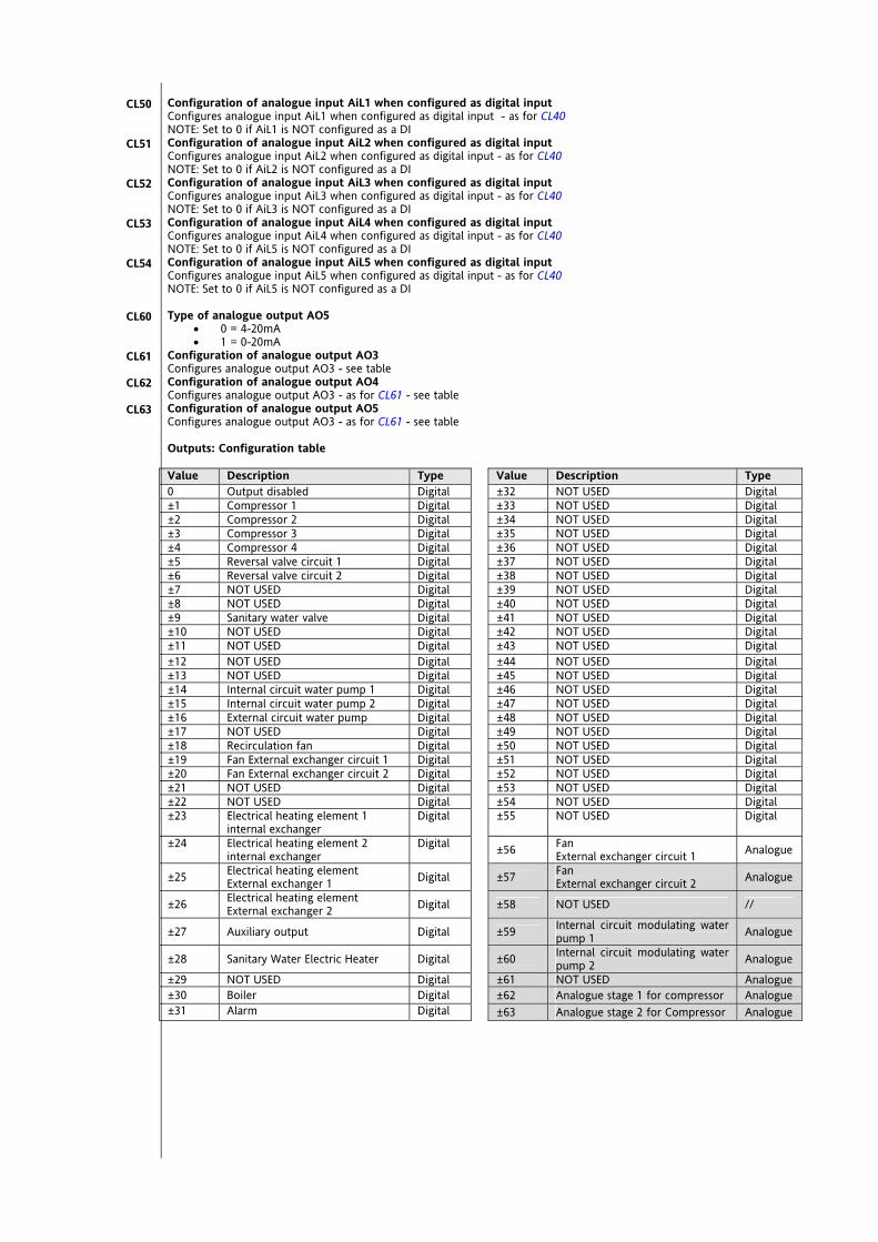
Configuration of analogue input AiL1 when configured as digital input Configures analogue input AiL1 when configured as digital input - as for CL40 NOTE: Set to 0 if AiL1 is NOT configured as a DI Configuration of analogue input AiL2 when configured as digital input Configures analogue input AiL2 when configured as digital input - as for CL40 NOTE: Set to 0 if AiL2 is NOT configured as a DI Configuration of analogue input AiL3 when configured as digital input Configures analogue input AiL3 when configured as digital input - as for CL40 NOTE: Set to 0 if AiL3 is NOT configured as a DI Configuration of analogue input AiL4 when configured as digital input Configures analogue input AiL4 when configured as digital input - as for CL40 NOTE: Set to 0 if AiL5 is NOT configured as a DI Configuration of analogue input AiL5 when configured as digital input Configures analogue input AiL5 when configured as digital input - as for CL40 NOTE: Set to 0 if AiL5 is NOT configured as a DI Type of analogue output AO5
0 = 4-20mA 1 = 0-20mA
Configuration of analogue output AO3 Configures analogue output AO3 - see table Configuration of analogue output AO4 Configures analogue output AO3 - as for CL61 - see table Configuration of analogue output AO5 Configures analogue output AO3 - as for CL61 - see table Outputs: Configuration table Value Description Type Value Description Type 0 Output disabled Digital ±32 NOT USED Digital ±1 Compressor 1 Digital ±33 NOT USED Digital ±2 Compressor 2 Digital ±34 NOT USED Digital ±3 Compressor 3 Digital ±35 NOT USED Digital ±4 Compressor 4 Digital ±36 NOT USED Digital ±5 Reversal valve circuit 1 Digital ±37 NOT USED Digital ±6 Reversal valve circuit 2 Digital ±38 NOT USED Digital ±7 NOT USED Digital ±39 NOT USED Digital ±8 NOT USED Digital ±40 NOT USED Digital ±9 Sanitary water valve Digital ±41 NOT USED Digital ±10 NOT USED Digital ±42 NOT USED Digital ±11 NOT USED Digital ±43 NOT USED Digital ±12 NOT USED Digital ±44 NOT USED Digital ±13 NOT USED Digital ±45 NOT USED Digital ±14 Internal circuit water pump 1 Digital ±46 NOT USED Digital ±15 Internal circuit water pump 2 Digital ±47 NOT USED Digital ±16 External circuit water pump Digital ±48 NOT USED Digital ±17 NOT USED Digital ±49 NOT USED Digital ±18 Recirculation fan Digital ±50 NOT USED Digital ±19 Fan External exchanger circuit 1 Digital ±51 NOT USED Digital ±20 Fan External exchanger circuit 2 Digital ±52 NOT USED Digital ±21 NOT USED Digital ±53 NOT USED Digital ±22 NOT USED Digital ±54 NOT USED Digital ±23 Electrical heating element 1
internal exchanger Digital ±55 NOT USED Digital
±24 Electrical heating element 2 internal exchanger
Digital ±56 Fan External exchanger circuit 1 Analogue
±25 Electrical heating element External exchanger 1 Digital ±57 Fan
External exchanger circuit 2 Analogue
±26 Electrical heating element External exchanger 2 Digital ±58 NOT USED //
±27 Auxiliary output Digital ±59 Internal circuit modulating water pump 1 Analogue
±28 Sanitary Water Electric Heater Digital ±60 Internal circuit modulating water pump 2 Analogue
±29 NOT USED Digital ±61 NOT USED Analogue ±30 Boiler Digital ±62 Analogue stage 1 for compressor Analogue ±31 Alarm Digital ±63 Analogue stage 2 for Compressor Analogue
CL50
CL51
CL52
CL53
CL54
CL60
CL61
CL62
CL63
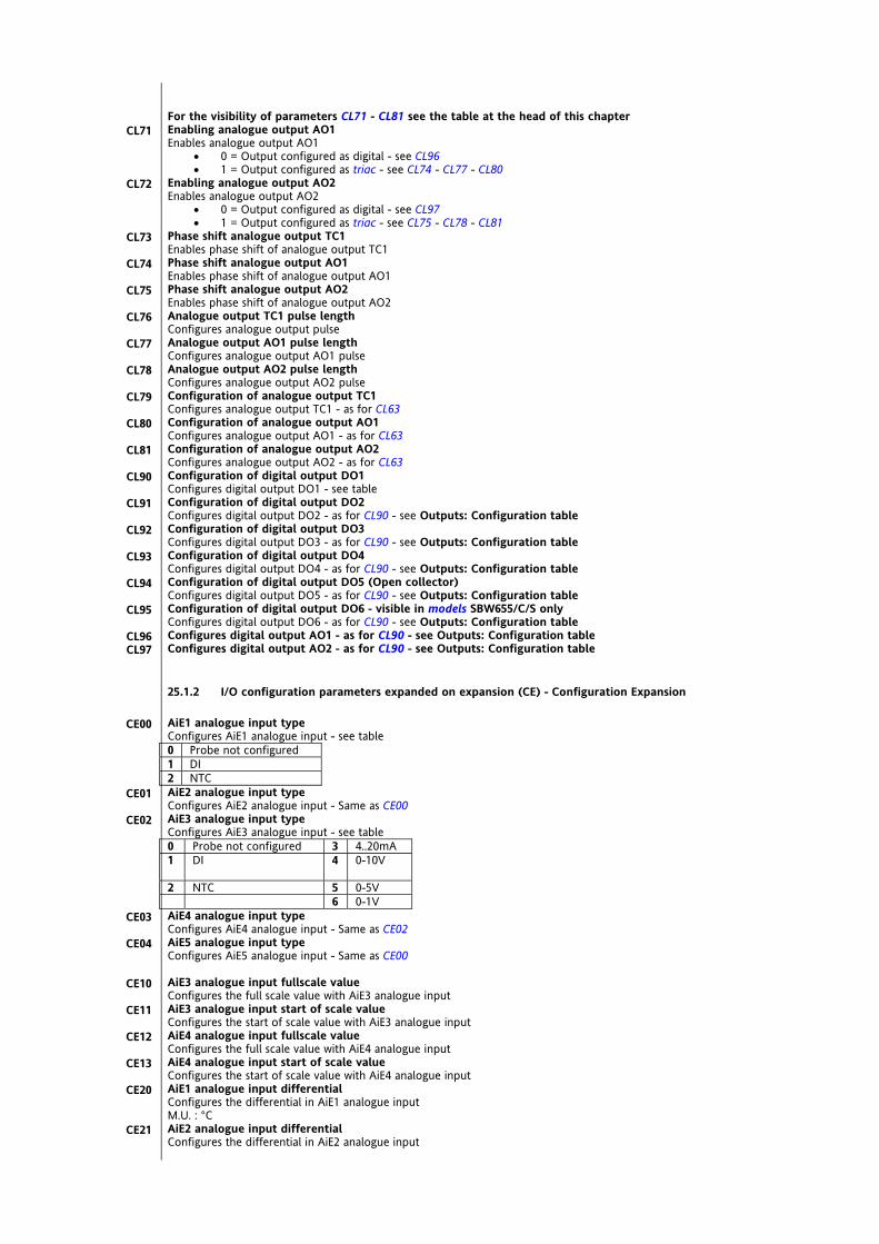
For the visibility of parameters CL71 - CL81 see the table at the head of this chapter Enabling analogue output AO1 Enables analogue output AO1
0 = Output configured as digital - see CL96 1 = Output configured as triac - see CL74 - CL77 - CL80
Enabling analogue output AO2 Enables analogue output AO2
0 = Output configured as digital - see CL97 1 = Output configured as triac - see CL75 - CL78 - CL81
Phase shift analogue output TC1 Enables phase shift of analogue output TC1 Phase shift analogue output AO1 Enables phase shift of analogue output AO1 Phase shift analogue output AO2 Enables phase shift of analogue output AO2 Analogue output TC1 pulse length Configures analogue output pulse Analogue output AO1 pulse length Configures analogue output AO1 pulse Analogue output AO2 pulse length Configures analogue output AO2 pulse Configuration of analogue output TC1 Configures analogue output TC1 - as for CL63 Configuration of analogue output AO1 Configures analogue output AO1 - as for CL63 Configuration of analogue output AO2 Configures analogue output AO2 - as for CL63 Configuration of digital output DO1 Configures digital output DO1 - see table Configuration of digital output DO2 Configures digital output DO2 - as for CL90 - see Outputs: Configuration table Configuration of digital output DO3 Configures digital output DO3 - as for CL90 - see Outputs: Configuration table Configuration of digital output DO4 Configures digital output DO4 - as for CL90 - see Outputs: Configuration table Configuration of digital output DO5 (Open collector) Configures digital output DO5 - as for CL90 - see Outputs: Configuration table Configuration of digital output DO6 - visible in models SBW655/C/S only Configures digital output DO6 - as for CL90 - see Outputs: Configuration table Configures digital output AO1 - as for CL90 - see Outputs: Configuration table Configures digital output AO2 - as for CL90 - see Outputs: Configuration table
25.1.2 I/O configuration parameters expanded on expansion (CE) - Configuration Expansion AiE1 analogue input type Configures AiE1 analogue input - see table 0 Probe not configured 1 DI 2 NTC AiE2 analogue input type Configures AiE2 analogue input - Same as CE00 AiE3 analogue input type Configures AiE3 analogue input - see table 0 Probe not configured 3 4..20mA 1 DI 4 0-10V
2 NTC 5 0-5V 6 0-1V AiE4 analogue input type Configures AiE4 analogue input - Same as CE02 AiE5 analogue input type Configures AiE5 analogue input - Same as CE00 AiE3 analogue input fullscale value Configures the full scale value with AiE3 analogue input AiE3 analogue input start of scale value Configures the start of scale value with AiE3 analogue input AiE4 analogue input fullscale value Configures the full scale value with AiE4 analogue input AiE4 analogue input start of scale value Configures the start of scale value with AiE4 analogue input AiE1 analogue input differential Configures the differential in AiE1 analogue input M.U. : °C AiE2 analogue input differential Configures the differential in AiE2 analogue input
CL71
CL72
CL73
CL74
CL75
CL76
CL77
CL78
CL79
CL80
CL81
CL90
CL91
CL92
CL93
CL94
CL95
CL96 CL97
CE00
CE01
CE02
CE03
CE04
CE10
CE11
CE12
CE13
CE20
CE21

M.U. : °C AiE3 analogue input differential Configures the differential in AiE3 analogue input M.U. : °C/bar AiE4 analogue input differential Configures the differential in AiE4 analogue input M.U. : °C/bar AiE5 analogue input differential Configures the differential in AiE5 analogue input M.U. : °C AiE1 analogue input configuration Configures AiE1 analogue input - see table 0 input disabled 1 Water/air inlet temperature
internal exchanger 2 Water/air outlet temperature
internal exchanger 3 Water outlet temperature
internal exchanger circuit 1 4 Water outlet temperature
internal exchanger circuit 2 5 External exchanger temperature circuit 1 6 External exchanger temperature circuit 2 7 Water inlet temperature
recovery (or external) exchanger 8 Water outlet temperature
recovery (or external) exchanger 9 External temperature 10 Water recovery temperature 11 Sanitary water temperature 12 NOT USED 13 NOT USED 14 NOT USED 15 NOT USED 16 Temperature display
CE22
CE23
CE24
CE30

AiE2 analogue input configuration Configures AiE2 analogue input - Same as CE30 AiE3 analogue input configuration Configures AiE3 analogue input - see table 0 input disabled 16 Temperature display 1 Water/air inlet temperature
internal exchanger 17 NOT USED
2 Water/air outlet temperature internal exchanger
18 NOT USED
3 Water outlet temperature internal exchanger circuit 1
19 NOT USED
4 Water outlet temperature internal exchanger circuit 2
20 NOT USED
5 External exchanger temperature circuit 1 21 High pressure input circuit 1 6 External exchanger temperature circuit 2 22 High pressure input circuit 2 7 Water inlet temperature
recovery (or external) exchanger 23 Low pressure input circuit 1
8 Water outlet temperature recovery (or external) exchanger
24 Low pressure input circuit 2
9 External temperature 25 Input for dynamic set point 10 NOT USED 26 Internal exchanger pressure circuit 1 11 Sanitary water temperature 27 Internal exchanger pressure circuit 2 12 NOT USED 28 External exchanger pressure circuit 1 13 NOT USED 29 External exchanger pressure circuit 2 14 NOT USED 30 Pressure display 15 NOT USED AiE4 analogue input configuration – Same as CE32 AiE5 analogue input configuration – Same as CE32 DI1 digital input configuration Configures the DI1 digital input – see table 0 Input disabled ±31 High pressure pressure switch C2 ±1 Remote STD-BY ±32 Low pressure pressure switch C1 ±2 remote OFF ±33 Low pressure pressure switch C2 ±3 Remote Summer/Winter ±34 Compressor 1 oil pressure switch ±4 Power step 1 request ±35 Compressor 2 oil pressure switch ±5 Power step 2 request ±36 Compressor 3 oil pressure switch ±6 Power step 3 request ±37 Compressor 4 oil pressure switch ±7 Power step 4 request ±38 NOT USED ±8 Digital input heat step 1 request ±39 External exchanger fan thermal switch C1 ±9 Digital input heat step 2 request ±40 External exchanger fan thermal switch C2 ±10 Digital input heat step 3 request ±41 Internal exchanger fan thermoswitch ±11 Digital input heat step 4 request ±42 NOT USED ±12 Digital input cool step 1 request ±43 Compressor 1 thermoswitch ±13 Digital input cool step 2 request ±44 Compressor 2 thermoswitch ±14 Digital input cool step 3 request ±45 Compressor 3 thermal switch ±15 Digital input cool step 4 request ±46 Compressor 4 thermal switch ±16 Block compressor 1 ±47 Internal circuit pump 1 thermal protection ±17 Block compressor 2 ±48 Internal circuit pump 2 thermal protection ±18 Block compressor 3 ±49 External circuit pump thermal protection ±19 Block compressor 4 ±50 Internal exchanger electric heater 1 thermoswitch ±20 Heat pump lock ±51 Internal exchanger electric heater 2 thermoswitch ±21 Power limited to 50% ±52 Auxiliary output alarm ±22 Economy input ±53 NOT USED ±23 NOT USED ±54 NOT USED ±24 General alarm ±55 Primary circuit flow switch ±25 End of defrost C1 ±56 External circuit flow switch (Recovery) ±26 End of defrost C2 ±57 NOT USED ±27 NOT USED ±58 Display ±28 NOT USED ±29 NOT USED ±30 High pressure pressure switch C1 DI2 digital input configuration Configures DI2 digital input – Same as CE40 DI3 digital input configuration Configures DI3 digital input – Same as CE40 DI4 digital input configuration Configures DI4 digital input – Same as CL40 DI5 digital input configuration Configures DI5 digital input – Same as CL40 DI6 digital input configuration Configures DI6 digital input – Same as CL40
CE31
CE32
CE33 CE34
CE40
CE41
CE42
CE43
CL44
CL45

AiE1 analogue input configuration when configured as digital input Configures AiE1 analogue input when configured as digital input – Same as CE40 NOTE: Set = 0 if AiE1 is NOT configured as DI AiE2 analogue input configuration when configured as digital input Configures AiE2 analogue input when configured as digital input - Same as CE40 NOTE: Set = 0 if AiE2 is NOT configured as DI AiE3 analogue input configuration when configured as digital input Configures AiE3 analogue input when configured as digital input - Same as CE40 NOTE: Set = 0 if AiE3 is NOT configured as DI AiE4 analogue input configuration when configured as digital input Configures AiE4 analogue input when configured as digital input - Same as CE40 NOTE: Set = 0 if AiE5 is NOT configured as DI AiE5 analogue input configuration when configured as digital input Configures AiE5 analogue input when configured as digital input - Same as CE40 NOTE: Set = 0 if AiE5 is NOT configured as DI AOE5 analogue output type
0 = 4-20mA 1 = 0-20mA
AOE3 analogue output configuration Configures AOE3 analogue output - see table AOE4 analogue output configuration Configures AOE3 analogue output - same as CE61 - see table AOE5 analogue output configuration Configures AOE3 analogue output - same as CL61 - see table Outputs: configuration table Value Description Type Value Description Type 0 Output disabled Digital ±32 NOT USED Digital ±1 Compressor 1 Digital ±33 NOT USED Digital ±2 Compressor 2 Digital ±34 NOT USED Digital ±3 Compressor 3 Digital ±35 NOT USED Digital ±4 Compressor 4 Digital ±36 NOT USED Digital ±5 Reversal valve circuit 1 Digital ±37 NOT USED Digital ±6 Reversal valve circuit 2 Digital ±38 NOT USED Digital ±7 NOT USED Digital ±39 NOT USED Digital ±8 NOT USED Digital ±40 NOT USED Digital ±9 Sanitary water valve Digital ±41 NOT USED Digital ±10 NOT USED Digital ±42 NOT USED Digital ±11 NOT USED Digital ±43 NOT USED Digital ±12 NOT USED Digital ±44 NOT USED Digital ±13 NOT USED Digital ±45 NOT USED Digital ±14 Internal circuit water pump 1 Digital ±46 NOT USED Digital ±15 Internal circuit water pump 2 Digital ±47 NOT USED Digital ±16 External circuit water pump Digital ±48 NOT USED Digital ±17 NOT USED Digital ±49 NOT USED Digital ±18 Recirculation fan Digital ±50 NOT USED Digital ±19 Fan External exchanger circuit 1 Digital ±51 NOT USED Digital ±20 Fan External exchanger circuit 2 Digital ±52 NOT USED Digital ±21 NOT USED Digital ±53 NOT USED Digital ±22 NOT USED Digital ±54 NOT USED Digital ±23 Electrical heating element 1
internal exchanger Digital ±55 NOT USED Digital
±24 Electrical heating element 2 internal exchanger
Digital ±56 Fan External exchanger circuit 1 Analogue
±25 Electrical heating element External exchanger 1 Digital ±57 Fan
External exchanger circuit 2 Analogue
±26 Electrical heating element External exchanger 2 Digital ±58 NOT USED //
±27 Auxiliary output Digital ±59 Internal circuit modulating water pump 1 Analogue
±28 Sanitary Water Electric Heater Digital ±60 Internal circuit modulating water pump 2 Analogue
±29 NOT USED Digital ±61 NOT USED Analogue ±30 Boiler Digital ±62 Analogue stage 1 for compressor Analogue ±31 Alarm Digital ±63 Analogue stage 2 for Compressor Analogue If multiple outputs are configured to run the same resource, the outputs will be activated in parallel.
CE50
CE51
CE52
CE53
CE54
CE60
CE61
CE62
CE63
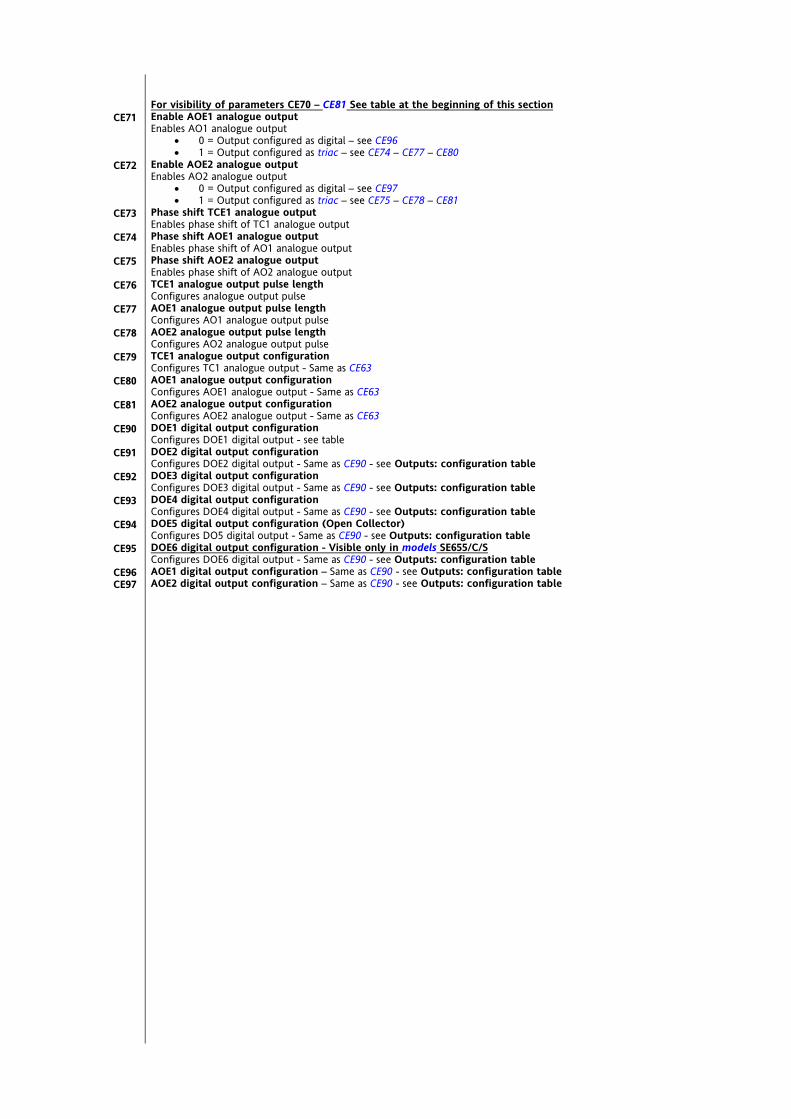
For visibility of parameters CE70 – CE81 See table at the beginning of this section Enable AOE1 analogue output Enables AO1 analogue output
0 = Output configured as digital – see CE96 1 = Output configured as triac – see CE74 – CE77 – CE80
Enable AOE2 analogue output Enables AO2 analogue output
0 = Output configured as digital – see CE97 1 = Output configured as triac – see CE75 – CE78 – CE81
Phase shift TCE1 analogue output Enables phase shift of TC1 analogue output Phase shift AOE1 analogue output Enables phase shift of AO1 analogue output Phase shift AOE2 analogue output Enables phase shift of AO2 analogue output TCE1 analogue output pulse length Configures analogue output pulse AOE1 analogue output pulse length Configures AO1 analogue output pulse AOE2 analogue output pulse length Configures AO2 analogue output pulse TCE1 analogue output configuration Configures TC1 analogue output - Same as CE63 AOE1 analogue output configuration Configures AOE1 analogue output - Same as CE63 AOE2 analogue output configuration Configures AOE2 analogue output - Same as CE63 DOE1 digital output configuration Configures DOE1 digital output - see table DOE2 digital output configuration Configures DOE2 digital output - Same as CE90 - see Outputs: configuration table DOE3 digital output configuration Configures DOE3 digital output - Same as CE90 - see Outputs: configuration table DOE4 digital output configuration Configures DOE4 digital output - Same as CE90 - see Outputs: configuration table DOE5 digital output configuration (Open Collector) Configures DO5 digital output - Same as CE90 - see Outputs: configuration table DOE6 digital output configuration - Visible only in models SE655/C/S Configures DOE6 digital output - Same as CE90 - see Outputs: configuration table AOE1 digital output configuration – Same as CE90 - see Outputs: configuration table AOE2 digital output configuration – Same as CE90 - see Outputs: configuration table
CE71
CE72
CE73
CE74
CE75
CE76
CE77
CE78
CE79
CE80
CE81
CE90
CE91
CE92
CE93
CE94
CE95
CE96 CE97
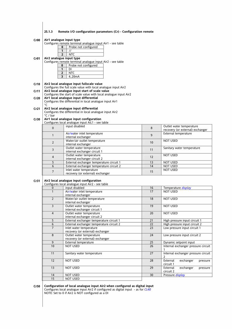
25.1.3 Remote I/O configuration parameters (Cr) - Configuration remote Air1 analogue input type Configures remote terminal analogue input Air1 - see table
0 Probe not configured 1 // 2 NTC
Air2 analogue input type Configures remote terminal analogue input Air2 - see table
0 Probe not configured 1 DI 2 NTC 3 4..20mA
Air2 local analogue input fullscale value Configures the full scale value with local analogue input Air2 Air2 local analogue input start of scale value Configures the start of scale value with local analogue input Air2 Air1 local analogue input differential Configures the differential in local analogue input Air1 °C Air2 local analogue input differential Configures the differential in local analogue input Air2 °C / bar Air1 local analogue input configuration Configures local analogue input AiL1 - see table
0 input disabled 8 Outlet water temperature recovery (or external) exchanger
1 Air/water inlet temperature internal exchanger 9 External temperature
2 Water/air outlet temperature internal exchanger 10 NOT USED
3 Outlet water temperature internal exchanger circuit 1 11 Sanitary water temperature
4 Outlet water temperature internal exchanger circuit 2 12 NOT USED
5 External exchanger temperature circuit 1 13 NOT USED 6 External exchanger temperature circuit 2 14 NOT USED
7 Inlet water temperature recovery (or external) exchanger 15 NOT USED
Air2 local analogue input configuration Configures local analogue input Air2 - see table
0 input disabled 16 Temperature display 1 Air/water inlet temperature
internal exchanger 17 NOT USED
2 Water/air outlet temperature internal exchanger
18 NOT USED
3 Outlet water temperature internal exchanger circuit 1
19 NOT USED
4 Outlet water temperature internal exchanger circuit 2
20 NOT USED
5 External exchanger temperature circuit 1 21 High pressure input circuit 1 6 External exchanger temperature circuit 2 22 High pressure input circuit 2 7 Inlet water temperature
recovery (or external) exchanger 23 Low pressure input circuit 1
8 Outlet water temperature recovery (or external) exchanger
24 Low pressure input circuit 2
9 External temperature 25 Dynamic setpoint input 10 NOT USED 26 Internal exchanger pressure circuit
1 11 Sanitary water temperature 27 Internal exchanger pressure circuit
2 12 NOT USED 28 External exchanger pressure
circuit 1 13 NOT USED 29 External exchanger pressure
circuit 2 14 NOT USED 30 Pressure display 15 NOT USED
Configuration of local analogue input Air2 when configured as digital input Configures local analogue input Air2 if configured as digital input - as for CL40 NOTE: Set to 0 if Air2 is NOT configured as a DI
Cr00
Cr01
Cr10
Cr11
Cr20
Cr21
Cr30
Cr31
Cr50
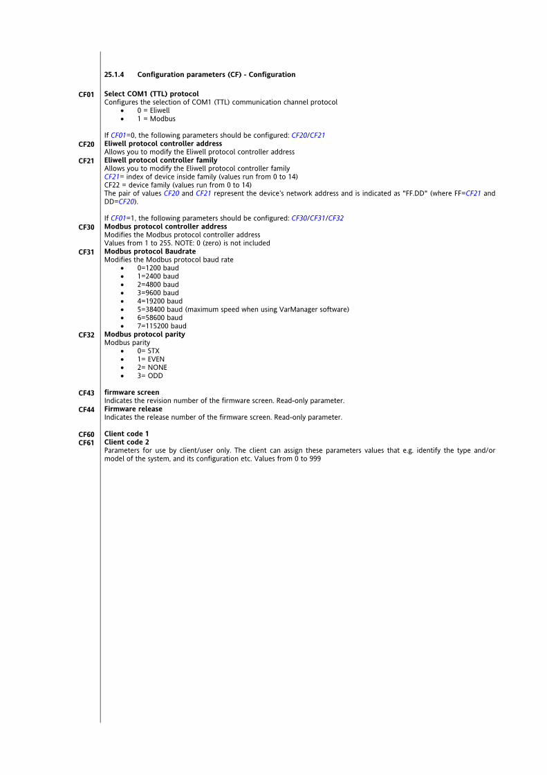
25.1.4 Configuration parameters (CF) - Configuration Select COM1 (TTL) protocol Configures the selection of COM1 (TTL) communication channel protocol
0 = Eliwell 1 = Modbus
If CF01=0, the following parameters should be configured: CF20/CF21 Eliwell protocol controller address Allows you to modify the Eliwell protocol controller address Eliwell protocol controller family Allows you to modify the Eliwell protocol controller family CF21= index of device inside family (values run from 0 to 14) CF22 = device family (values run from 0 to 14) The pair of values CF20 and CF21 represent the device’s network address and is indicated as "FF.DD" (where FF=CF21 and DD=CF20). If CF01=1, the following parameters should be configured: CF30/CF31/CF32 Modbus protocol controller address Modifies the Modbus protocol controller address Values from 1 to 255. NOTE: 0 (zero) is not included Modbus protocol Baudrate Modifies the Modbus protocol baud rate
0=1200 baud 1=2400 baud 2=4800 baud 3=9600 baud 4=19200 baud 5=38400 baud (maximum speed when using VarManager software) 6=58600 baud 7=115200 baud
Modbus protocol parity Modbus parity
0= STX 1= EVEN 2= NONE 3= ODD
firmware screen Indicates the revision number of the firmware screen. Read-only parameter. Firmware release Indicates the release number of the firmware screen. Read-only parameter. Client code 1 Client code 2 Parameters for use by client/user only. The client can assign these parameters values that e.g. identify the type and/or model of the system, and its configuration etc. Values from 0 to 999
CF01
CF20
CF21
CF30
CF31
CF32
CF43
CF44
CF60 CF61

25.1.5 User interface parameters (UI) - User Interface SBW600 utility led configuration Configuration of LED 1 Configuration of LED 2 Configuration of LED 3 Configuration of LED 4 Configuration of LED 5 Configuration of LED 6 Configuration of LED 7 Configures LED 1…7 LED utilities table
LED symbol on display
LED SBW600 / LED SKW22 22L
Parameter SBW600 /
SKW22 22L
Default SBW600 / SKW22 22L
Default SBW600 Default icon
on front panel
SBW600 LED 1 / 11
(first from left) UI00 / UI30 50 / 50 Output step 1
LED 2 /12 UI01 / UI31 51 / 51 Output step 2
LED 3 /13 UI02 / UI32 14 / 0 Internal circuit water pump 1 LED 4 /14 UI03 / UI33 16 / 0 External circuit water pump LED 5 /15 UI04 /UI34 23 / 23 Internal exchanger electric heater
LED 6 /16 UI05 /UI35 9* / 0 Sanitary water valve LED 7 /17 UI06 /UI36 30 / 14 Boiler
LED symbol on display
LED SBW600 Parameter SBW600
Economy LED UI07=0 dS00=0
UI07=0 dS00=1
UI07=1 dS00=0
NOT enabled (LED off)
Economy LED UI07=1 dS00=1
Enabled (dynamic setpoint)
* the LED is permanently on when in AS mode and with heating in progress, blinking when in AS mode and heating not in progress See Outputs: configuration table with the following exceptions:
Value Description Notes ±50 Power step 1 output
±51 Power step 2 output
±52 Power step 3 output
±53 Power step 4 output
values used only for configuring the user interface LEDs, and associated with the power steps requested by the main temperature regulator
… ±70 internal pump 1 output or
internal pump 2 output or both
±71 external exchanger fan circuit 1 output Or external exchanger fan circuit 2 output or both
±72 internal exchanger electric heater 1 output Or internal exchanger electric heater 2 output or both
±73 external exchanger heater 1 output or external exchanger heater 2 output or both
±74 circuit 1 heat pump lock status or
Digital
values used only for configuring the user interface
LEDs
UI00 UI01 UI02 UI03 UI04 UI05 UI06

Value Description Notes circuit 2 heat pump lock status or both
Configuration of Economy LED To configure the Economy LED (if=1,2 the economy LED on the display will be permanently on)
0 = LED disabled 1 = dynamic setpoint 2 = heat pump lock
Select main display Selects the main display 0 AiL1 analogue input 8 NOT USED 1 AiL2 analogue input 9 NOT USED 2 AiL3 analogue input 10 NOT USED 3 AiL4 analogue input 11 NOT USED 4 AiL5 analogue input 12 Clock 5 Remote terminal AIR1 analogue input 1 13 Setpoint set 6 Remote terminal AIR2 analogue input 2 14 Real setpoint 7 NOT USED Which we will refer to as:
Display
Display A Display B*
4-digit clock display 2 and a half digit display + sign, see parameter UI11
Select main display (remote terminal) SKW1 Selects the main display* remote terminal *Note: 2 and a half digit display + sign See Ui10 Enable ACS in standby / Manual defrost function from [UP] key To enable or disable the Sanitary water in standby function from [UP] key or manual defrost depending on model
0 = Key not enabled for the function 1 = Key enabled for the function
Enable mode function from key Enables/disables mode selection ([esc] key) (mode function) from a key
0 = Key not enabled for the function 1 = Key enabled for the function
Enable disp function from key Enables/disables configuration of the main display from a key [set] (disp function)
0 = Key not enabled for the function 1 = Key enabled for the function
Enable standby function from [DOWN] key To enable or disable standby function from DOWN key
0 = Key not enabled for the function 1 = Key enabled for the function
Enable “set” function from key Enables/disables access via the "set" to machine state menu and relative subfolders
0 = Key not enabled for the function 1 = Key enabled for the function
Setpoint edit function enable from main screen Parameter allows you to enable Setpoint modification on the main display with the UP and DOWN keys.
0 = Key not enabled for the function 1 = Key enabled for the function
UI07
UI10
UI11
UI20
UI21
UI22
UI23
UI24
UI25
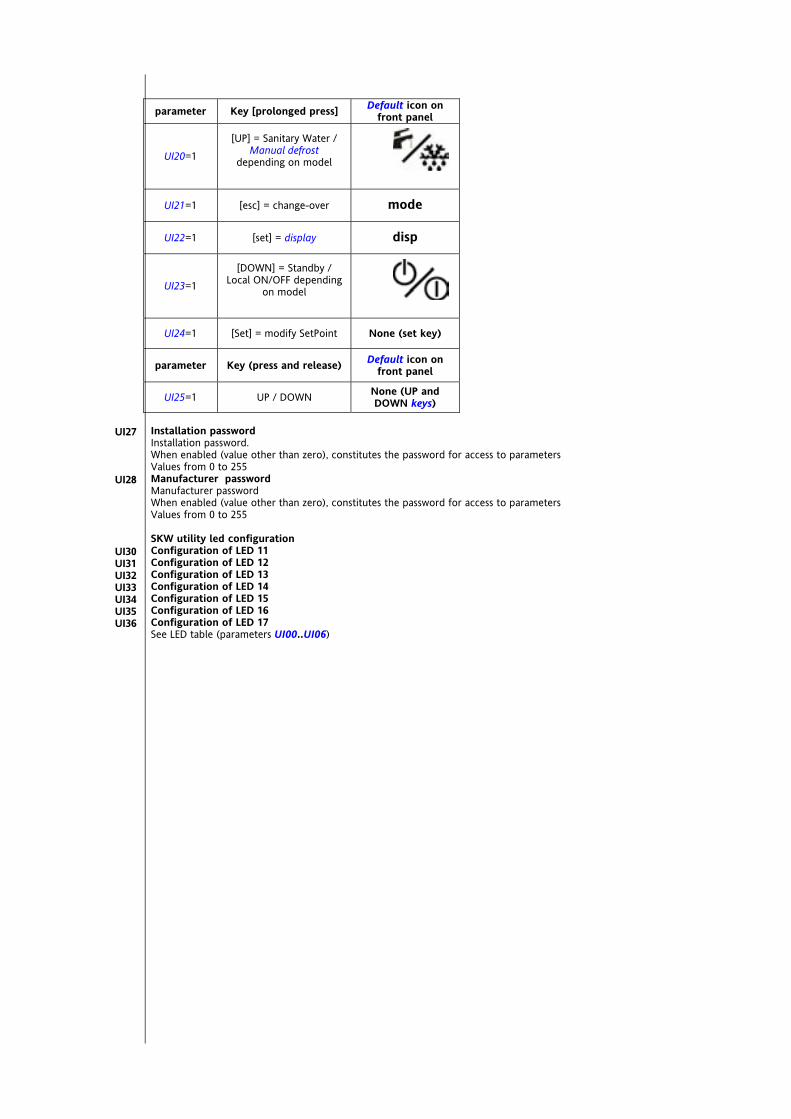
<IMG INFO> 56,7 39,65 1 2 51 -28,35 -1
<IMG INFO> 56,7 38,5 1 2 51 -28,35 -1
parameter Key [prolonged press] Default icon on front panel
UI20=1
[UP] = Sanitary Water / Manual defrost
depending on model
UI21=1 [esc] = change-over mode
UI22=1 [set] = display disp
UI23=1
[DOWN] = Standby / Local ON/OFF depending
on model
UI24=1 [Set] = modify SetPoint None (set key)
parameter Key (press and release) Default icon on front panel
UI25=1 UP / DOWN None (UP and DOWN keys)
Installation password Installation password. When enabled (value other than zero), constitutes the password for access to parameters Values from 0 to 255 Manufacturer password Manufacturer password When enabled (value other than zero), constitutes the password for access to parameters Values from 0 to 255 SKW utility led configuration Configuration of LED 11 Configuration of LED 12 Configuration of LED 13 Configuration of LED 14 Configuration of LED 15 Configuration of LED 16 Configuration of LED 17 See LED table (parameters UI00..UI06)
UI27
UI28
UI30 UI31 UI32 UI33 UI34 UI35 UI36
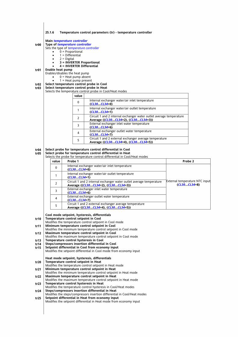
25.1.6 Temperature control parameters (tr) - temperature controller Main temperature controller Type of temperature controller Sets the type of temperature controller
0 = Proportional 1 = Differential 2 = Digital 3 = INVERTER Proportional 4 = INVERTER Differential
Enable heat pump Enables/disables the heat pump
0 = Heat pump absent 1 = Heat pump present
Select temperature control probe in Cool Select temperature control probe in Heat Selects the temperature control probe in Cool/Heat modes
value
0 Internal exchanger water/air inlet temperature (CL30…CL34=0)
1 Internal exchanger water/air outlet temperature (CL30…CL34=1)
2 Circuit 1 and 2 internal exchanger water outlet average temperature Average ((CL30…CL34=2), (CL30…CL34=3))
3 External exchanger inlet water temperature (CL30…CL34=6)
4 External exchanger outlet water temperature (CL30…CL34=7)
5 Circuit 1 and 2 external exchanger average temperature Average ((CL30…CL34=4), (CL30…CL34=5))
Select probe for temperature control differential in Cool Select probe for temperature control differential in Heat Selects the probe for temperature control differential in Cool/Heat modes
value Probe 1 Probe 2
0 Internal exchanger water/air inlet temperature (CL30…CL34=0)
1 Internal exchanger water/air outlet temperature (CL30…CL34=1)
2 Circuit 1 and 2 internal exchanger water outlet average temperature Average ((CL30…CL34=2), (CL30…CL34=3))
3 External exchanger inlet water temperature (CL30…CL34=6)
4 External exchanger outlet water temperature (CL30…CL34=7)
External temperature NTC input (CL30…CL34=8)
5 Circuit 1 and 2 external exchanger average temperature Average ((CL30…CL34=4), (CL30…CL34=5))
Cool mode setpoint, hysteresis, differentials Temperature control setpoint in Cool Modifies the temperature control setpoint in Cool mode Minimum temperature control setpoint in Cool Modifies the minimum temperature control setpoint in Cool mode Maximum temperature control setpoint in Cool Modifies the maximum temperature control setpoint in Cool mode Temperature control hysteresis in Cool Steps/compressors insertion differential in Cool Setpoint differential in Cool from economy input Modifies the setpoint differential in Cool mode from economy input Heat mode setpoint, hysteresis, differentials Temperature control setpoint in Heat Modifies the temperature control setpoint in Heat mode Minimum temperature control setpoint in Heat Modifies the minimum temperature control setpoint in Heat mode Maximum temperature control setpoint in Heat Modifies the maximum temperature control setpoint in Heat mode Temperature control hysteresis in Heat Modifies the temperature control hysteresis in Cool/Heat modes Steps/compressors insertion differential in Heat Modifies the steps/compressors insertion differential in Cool/Heat modes Setpoint differential in Heat from economy input Modifies the setpoint differential in Heat mode from economy input
tr00
tr01
tr02 tr03
tr04 tr05
tr10
tr11
tr12
tr13 tr14 tr15
tr20
tr21
tr22
tr23
tr24
tr25
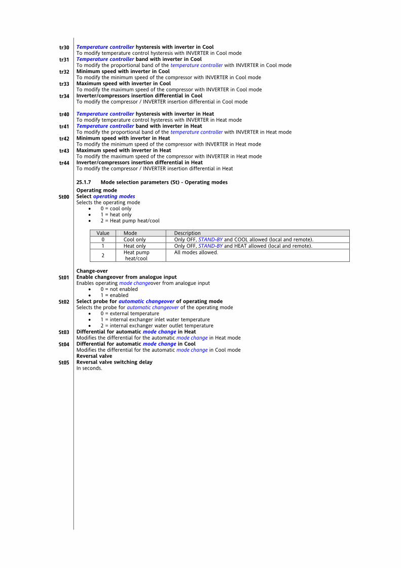
Temperature controller hysteresis with inverter in Cool To modify temperature control hysteresis with INVERTER in Cool mode Temperature controller band with inverter in Cool To modify the proportional band of the temperature controller with INVERTER in Cool mode Minimum speed with inverter in Cool To modify the minimum speed of the compressor with INVERTER in Cool mode Maximum speed with inverter in Cool To modify the maximum speed of the compressor with INVERTER in Cool mode Inverter/compressors insertion differential in Cool To modify the compressor / INVERTER insertion differential in Cool mode Temperature controller hysteresis with inverter in Heat To modify temperature control hysteresis with INVERTER in Heat mode Temperature controller band with inverter in Heat To modify the proportional band of the temperature controller with INVERTER in Heat mode Minimum speed with inverter in Heat To modify the minimum speed of the compressor with INVERTER in Heat mode Maximum speed with inverter in Heat To modify the maximum speed of the compressor with INVERTER in Heat mode Inverter/compressors insertion differential in Heat To modify the compressor / INVERTER insertion differential in Heat
25.1.7 Mode selection parameters (St) - Operating modes Operating mode Select operating modes Selects the operating mode
0 = cool only 1 = heat only 2 = Heat pump heat/cool
Value Mode Description
0 Cool only Only OFF, STAND-BY and COOL allowed (local and remote). 1 Heat only Only OFF, STAND-BY and HEAT allowed (local and remote).
2 Heat pump heat/cool
All modes allowed.
Change-over Enable changeover from analogue input Enables operating mode changeover from analogue input
0 = not enabled 1 = enabled
Select probe for automatic changeover of operating mode Selects the probe for automatic changeover of the operating mode
0 = external temperature 1 = internal exchanger inlet water temperature 2 = internal exchanger water outlet temperature
Differential for automatic mode change in Heat Modifies the differential for the automatic mode change in Heat mode Differential for automatic mode change in Cool Modifies the differential for the automatic mode change in Cool mode Reversal valve Reversal valve switching delay In seconds.
tr30
tr31
tr32
tr33
tr34
tr40
tr41
tr42
tr43
tr44
St00
St01
St02
St03
St04
St05

25.1.8 Compressor Parameters (CP) - Compressor Type of plant Compressor type Selects the type of compressor
0 = simple (non-power stage) 1 = alternate power stage 2 = screw power stage
Number of circuits Selects the number of circuits
1 = 1 circuit 2 = 2 circuits
Number of compressors per circuit Selects the number of compressors per circuit
1 = 1 compressor 2 = 2 compressors 3 = 3 compressors 4 = 4 compressors
Number of power stages per compressor Selects the number of compressors per circuit
1 = 1 power stage 2 = 2 power stages 3 = 3 power stages
Plant resource management Enable circuit balancing Establishes circuit management
0 = saturation (circuits) 1 = balancing (circuits)
Enable compressor balancing Establishes circuit management
0 = saturation (compressors) 1 = balancing (compressors) 2 = NOT USED
Circuit selection criterion Establishes circuit selection
0 = hours balancing 1 = on sequence 1-->2; off sequence 2-->1
Compressor selection criterion Establishes the selection of compressors on each circuit
0 = hours balancing 1 = on sequence 1-->2-->3-->4; off sequence 4-->3-->2-->1 2 = operating time
Compressor running time for switch on sequence Modifies the compressor running time for the switch on sequence Compressor Protection Minimum time between the switching off and on of the same compressor Modifies the minimum time between the switching off and on of the same compressor Minimum time between the switching on of the same compressor Modifies the minimum time between the switching on of the same compressor Minimum compressor on time Modifies the minimum compressor switch on time Minimum time between the switching on of more than one compressor Modifies the minimum time between the switching on of more than one compressor Minimum time between the switching off of more than one compressor Modifies the minimum time between the switching off of more than one compressor Minimum compressor switch on time for increase in power stages Modifies the minimum compressor switch on time for an increase in power stages Minimum compressor switch on time for decrease in power stages Modifies the minimum compressor switch on time for a decrease in power stages Defrost compressor/step delay minimum Modifies the minimum time between the switching off and on in defrost
CP00
CP01
CP02
CP03
CP10
CP11
CP12
CP13
CP14
CP20
CP21
CP22
CP23
CP24
CP25
CP26
CP27

25.1.9 Internal circuit pump parameters (PI) - Internal pump Select internal circuit water pump operating mode To select operating mode of the internal circuit water pump
0 Pump disabled 1 Continuous (always on) 2 on request (pump on when compressor on)
Internal circuit water pump idle time due to antilock Modifies the internal circuit water pump idle time due to antilock Internal circuit water pump pick-up time Modifies the internal circuit water pump pick-up time Minimum internal circuit water pump start time Modifies the minimum compressor switch on time Maximum internal circuit water pump changeover start time Pump operation time, after which the active pump is switched off and replaced by the second pump if available. If = 0 the second pump is not called Enable internal circuit water pump on when antifreeze heaters active Enables the switching on of the internal circuit water pump when the antifreeze heaters are active
0 = Pump disabled 1 = Pump enabled
Enable internal circuit special water pump 0 = No enabling 1 = Enable pump when the boiler is on 2 = Enable modulating pump on the basis of the difference between Internal exchanger water/air inlet
temperature and Internal exchanger water/air outlet temperature. See configuration of analogue inputs Operation on call Delay internal circuit water pump on and compressor on Modifies the delay between switching on the internal circuit water pump and switching on the compressor Delay compressor off - internal circuit water pump off Modifies the delay between switching off the compressor and switching off the internal circuit water pump Internal circuit pump periodic activation interval Modifies the maximum pump off time after which the pump is forced on If modulating, it will be switched on a maximum speed Modulating function in Cool mode Minimum internal circuit water pump speed in Cool Modifies the minimum internal circuit water pump speed in Cool mode Maximum internal circuit water pump speed in Cool Modifies the maximum internal circuit water pump speed in Cool mode Minimum internal circuit water pump speed setpoint in Cool Modifies the minimum internal circuit water pump speed setpoint in Cool mode Internal circuit water pump proportional band in Cool Modifies the internal circuit water pump proportional band in Cool mode Fan speed setpoint to modulate internal circuit water pump in Cool Modifies the fan speed setpoint to modulate the internal circuit water pump in Cool mode Fan speed hysteresis to modulate internal circuit water pump in Cool Modifies fan speed hysteresis for modulation of the internal circuit water pump in Cool mode Modulating function in Heat mode Minimum internal circuit water pump speed in Heat Modifies the minimum internal circuit water pump speed in Heat mode Maximum internal circuit water pump speed in Heat Modifies the maximum internal circuit water pump speed in Heat mode Minimum internal circuit water pump speed setpoint in Heat Modifies the minimum internal circuit water pump speed setpoint in Heat mode Internal circuit water pump proportional band in Heat Modifies the internal circuit water pump proportional band in Heat mode Fan speed setpoint to modulate internal circuit water pump in Heat Modifies the fan speed setpoint to modulate the internal circuit water pump in Heat mode Fan speed hysteresis to modulate internal circuit water pump in Heat Modifies fan speed hysteresis for modulation of the internal circuit water pump in Heat mode
PI00
PI01
PI02
PI03
PI05
PI10
PI11
PI20
PI21
PI22
PI30
PI31
PI32
PI33
PI34
PI35
PI40
PI41
PI42
PI43
PI44
PI45
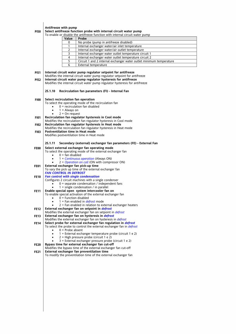
Antifreeze with pump Select antifreeze function probe with internal circuit water pump To enable or disable the antifreeze function with internal circuit water pump
Value Probe 0 No probe (pump in antifreeze disabled) 1 Internal exchanger water/air inlet temperature 2 Internal exchanger water/air outlet temperature 3 Internal exchanger water outlet temperature circuit 1 4 Internal exchanger water outlet temperature circuit 2 5 Circuit 1 and 2 internal exchanger water outlet minimum temperature 6 External temperature
Internal circuit water pump regulator setpoint for antifreeze Modifies the internal circuit water pump regulator setpoint for antifreeze Internal circuit water pump regulator hysteresis for antifreeze Modifies the internal circuit water pump regulator hysteresis for antifreeze
25.1.10 Recirculation fan parameters (FI) - Internal Fan Select recirculation fan operation To select the operating mode of the recirculation fan
0 = recirculation fan disabled 1 = Always on 2 = On request
Recirculation fan regulator hysteresis in Cool mode Modifies the recirculation fan regulator hysteresis in Cool mode Recirculation fan regulator hysteresis in Heat mode Modifies the recirculation fan regulator hysteresis in Heat mode Postventilation time in Heat mode Modifies postventilation time in Heat mode
25.1.11 Secondary (external) exchanger fan parameters (FE) - External Fan Select external exchanger fan operating mode To select the operating mode of the external exchanger fan
0 = fan disabled 1 = Continuous operation (Always ON) 2 = Operation on call (ON with compressor ON)
External exchanger fan pick-up time To vary the pick up time of the external exchanger fan FAN CONTROL IN DEFROST Fan control with single condensation Configures 2 circuit machines with a single condenser
0 = separate condensation / independent fans 1 = single condensation / in parallel
Enable special open system intercooler fan on To enable special activation of the external exchanger fan
0 = Function disabled 1 = Fan enabled in defrost mode 2 = Fan enabled in relation to external exchanger heaters
External exchanger fan on setpoint in defrost Modifies the external exchanger fan on setpoint in defrost External exchanger fan on hysteresis in defrost Modifies the external exchanger fan on hysteresis in defrost Select probe for external exchanger fan regulation in defrost To select the probe to control the external exchanger fan in defrost
0 = Probe absent 1 = External exchanger temperature probe (circuit 1 e 2) 2 = High pressure probe (circuit 1 e 2) 3 = External exchanger pressure probe (circuit 1 e 2)
Bypass time for external exchanger fan cut-off Modifies the bypass time of the external exchanger fan cut-off External exchanger fan preventilation time To modify the preventilation time of the external exchanger fan
PI50
PI51
PI52
FI00
FI01
FI02
FI03
FE00
FE01
FE10
FE11
FE12
FE13
FE14
FE20
FE21

FAN CONTROL IN COOLING Minimum speed external exchanger fan in Cool Modifies the minimum speed of the external exchanger fan in Cool mode Average speed external exchanger fan in Cool Modifies the average speed of the external exchanger fan in Cool mode Maximum speed external exchanger fan in Cool Modifies the maximum speed of the external exchanger fan in Cool mode Select probe for external exchanger fan regulation in Cool To select the probe to control the external exchanger fan in Cool mode
Value Description Regulation 0 No probe On or On/Off 1 External exchanger temperature (circuit 1 and 2) Direct 2 High pressure input (circuit 1 and 2) Direct 3 Low pressure input (circuit 1 and 2) Reversal 4 External exchanger pressure (circuit 1 and 2) Direct 5 Internal exchanger pressure (circuit 1 and 2) Reversal 6 Internal exchanger water/air inlet temperature Direct 7 Internal exchanger water/air outlet temperature Direct
External exchanger fan minimum speed setpoint in Cool Modifies the minimum speed setpoint of the external exchanger fan in Cool mode External exchanger maximum speed differential in Cool Modifies the maximum speed differential of the external exchanger fan in Cool mode External exchanger fan speed proportional band in Cool Modifies the proportional band of the external exchanger fan speed in Cool mode Maximum external exchanger fan hysteresis in Cool mode Modifies the maximum hysteresis of the external exchanger fan speed in Cool mode External exchanger fan cut-off hysteresis in Cool Modifies the cut-off hysteresis of the external exchanger fan in Cool mode External exchanger fan cut-off differential in Cool Modifies the cut-off differential for the external exchanger fan in Cool mode FAN CONTROL IN HEATING Minimum speed external exchanger fan in Heat Modifies the minimum speed of the external exchanger fan in Heat mode Average speed external exchanger fan in Heat Modifies the average speed of the external exchanger fan in Heat mode Maximum speed external exchanger fan in Heat Modifies the maximum speed of the external exchanger fan in Heat mode Select probe for external exchanger fan regulation in Heat To select the probe to control the external exchanger fan in Heat mode
Value Description Regulation 0 No probe On or On/Off 1 External exchanger temperature (circuit 1 and 2) Direct 2 High pressure input (circuit 1 and 2) Direct 3 Low pressure input (circuit 1 and 2) Reversal 4 External exchanger pressure (circuit 1 and 2) Direct 5 Internal exchanger pressure (circuit 1 and 2) Reversal 6 Internal exchanger water/air inlet temperature Direct 7 Internal exchanger water/air outlet temperature Direct
Minimum external exchanger fan speed setpoint in Heat Modifies the minimum speed setpoint of the external exchanger fan in Heat mode Maximum external exchanger speed differential in Heat Modifies the maximum speed differential of the external exchanger fan in Heat mode External exchanger fan speed proportional band in Heat Modifies the proportional band of the external exchanger fan speed in Heat mode Maximum external exchanger fan speed hysteresis in Heat Modifies the maximum hysteresis of the external exchanger fan speed in Heat mode External exchanger fan cut-off hysteresis in Heat Modifies the cut-off hysteresis of the external exchanger fan in Heat mode External exchanger fan cut-off differential in Heat Modifies the cut-off differential for the external exchanger fan in Heat mode
25.1.12 External circuit pump parameters (PE) - External Pump External circuit water pump mode selection Defines the operation of the external circuit water pump
0 = Pump disabled 1 = Continuous operation (Always ON) 2 = NOT USED 3 = Operation synchronised with external exchanger fans
FE30
FE31
FE32
FE33
FE34
FE35
FE36
FE37
FE38
FE39
FE50
FE51
FE52
FE53
FE54
FE55
FE56
FE57
FE58
FE59
PE00

25.1.13 Electric heater parameters (HI) - Electric Heaters Enable internal exchanger heaters in Standby To enable or disable external exchanger heaters in standby
0 = Heaters disabled 1 = Heaters enabled
Enable force heaters on during defrost To enable or disable force heaters on during defrost
0 = Heaters enabled (ON) when requested by temperature controller (antifreeze or integrated use) 1 = Heaters always enabled ON during defrost
ANTIFREEZE Select probe to regulate internal exchanger heater 1 during antifreeze To select the probe for regulation of internal exchanger heaters during antifreeze
0 = Internal exchanger water/air inlet temperature 1 = Internal exchanger water/air outlet temperature
Select probe to regulate internal exchanger heater 2 during antifreeze To select the probe for regulation of internal exchanger heaters during antifreeze
Value Hi10 / Hi11 Probe 0 No probe (antifreeze heater disabled) 1 Internal exchanger water/air inlet temperature 2 Internal exchanger water/air outlet temperature 3 Circuit 1 internal exchanger water outlet temperature 4 Circuit 2 internal exchanger water outlet temperature 5 Circuit 1 and 2 internal exchanger water outlet minimum temperature
Internal exchanger heater regulator setpoint for antifreeze Modifies the internal exchanger heater regulator setpoint for antifreeze Maximum internal exchanger heater regulator setpoint for antifreeze Modifies the maximum setpoint of the internal exchanger heater regulator for antifreeze Minimum internal exchanger heater regulator setpoint for antifreeze Modifies the minimum setpoint of the internal exchanger heater regulator for antifreeze Internal exchanger heater regulator hysteresis for antifreeze Modifies the hysteresis of the internal exchanger heater regulator for antifreeze INTEGRATION Selects internal exchanger heater operation for integration To enable or disable integrated use of internal exchanger heaters Value Description
0 Integration heaters disabled 1 Integration heaters with differential setpoint proportional to external temperature 2 Integration heaters with differential setpoint in steps to external temperature 3 Integration heaters with differential setpoint fixed
Internal exchanger heater dynamic differential setpoint in integrated use Modifies the dynamic differential setpoint of the internal exchanger heaters in integrated use Maximum dynamic differential internal exchanger heaters in integrated use Modifies the maximum dynamic differential of the internal exchanger heaters in integrated use Heater differential in integration mode with heat pump lock Modifies the start differential of the internal exchanger heaters in integrated use in case of heat pump lock Internal exchanger heater dynamic differential proportional band in integrated use Modifies the proportional band of the dynamic differential of the internal exchanger heaters in integrated use Internal exchanger heater regulator hysteresis in integrated use Modifies the hysteresis of the internal exchanger heaters in integrated use Differential setpoint internal exchanger heater 2 on in integrated use Modifies the differential setpoint to switch on internal exchanger heater 2 in integrated use
HI00
HI01
HI10
HI11
HI12
HI13
HI14
HI15
HI20
HI21 HI22
HI23
HI24
HI25
HI26
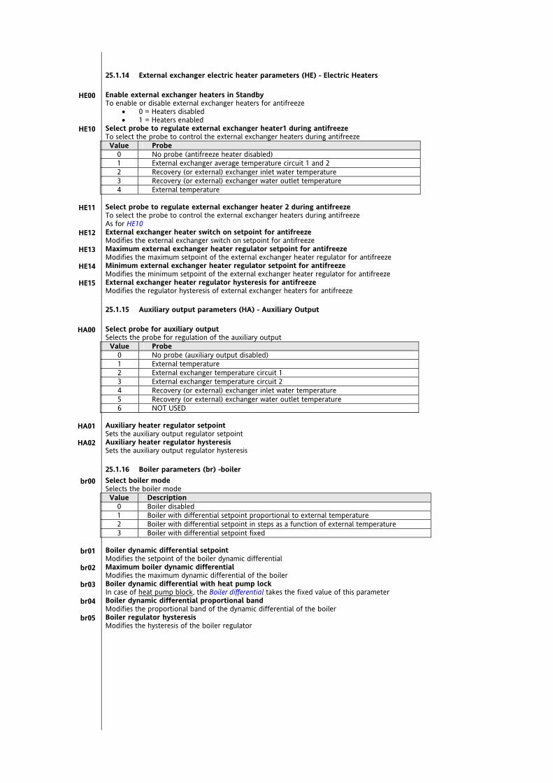
25.1.14 External exchanger electric heater parameters (HE) - Electric Heaters Enable external exchanger heaters in Standby To enable or disable external exchanger heaters for antifreeze
0 = Heaters disabled 1 = Heaters enabled
Select probe to regulate external exchanger heater1 during antifreeze To select the probe to control the external exchanger heaters during antifreeze Value Probe
0 No probe (antifreeze heater disabled) 1 External exchanger average temperature circuit 1 and 2 2 Recovery (or external) exchanger inlet water temperature 3 Recovery (or external) exchanger water outlet temperature 4 External temperature
Select probe to regulate external exchanger heater 2 during antifreeze To select the probe to control the external exchanger heaters during antifreeze As for HE10 External exchanger heater switch on setpoint for antifreeze Modifies the external exchanger switch on setpoint for antifreeze Maximum external exchanger heater regulator setpoint for antifreeze Modifies the maximum setpoint of the external exchanger heater regulator for antifreeze Minimum external exchanger heater regulator setpoint for antifreeze Modifies the minimum setpoint of the external exchanger heater regulator for antifreeze External exchanger heater regulator hysteresis for antifreeze Modifies the regulator hysteresis of external exchanger heaters for antifreeze
25.1.15 Auxiliary output parameters (HA) - Auxiliary Output Select probe for auxiliary output Selects the probe for regulation of the auxiliary output Value Probe
0 No probe (auxiliary output disabled) 1 External temperature 2 External exchanger temperature circuit 1 3 External exchanger temperature circuit 2 4 Recovery (or external) exchanger inlet water temperature 5 Recovery (or external) exchanger water outlet temperature 6 NOT USED
Auxiliary heater regulator setpoint Sets the auxiliary output regulator setpoint Auxiliary heater regulator hysteresis Sets the auxiliary output regulator hysteresis
25.1.16 Boiler parameters (br) -boiler Select boiler mode Selects the boiler mode Value Description
0 Boiler disabled 1 Boiler with differential setpoint proportional to external temperature 2 Boiler with differential setpoint in steps as a function of external temperature 3 Boiler with differential setpoint fixed
Boiler dynamic differential setpoint Modifies the setpoint of the boiler dynamic differential Maximum boiler dynamic differential Modifies the maximum dynamic differential of the boiler Boiler dynamic differential with heat pump lock In case of heat pump block, the Boiler differential takes the fixed value of this parameter Boiler dynamic differential proportional band Modifies the proportional band of the dynamic differential of the boiler Boiler regulator hysteresis Modifies the hysteresis of the boiler regulator
HE00
HE10
HE11
HE12
HE13
HE14
HE15
HA00
HA01
HA02
br00
br01
br02
br03
br04
br05
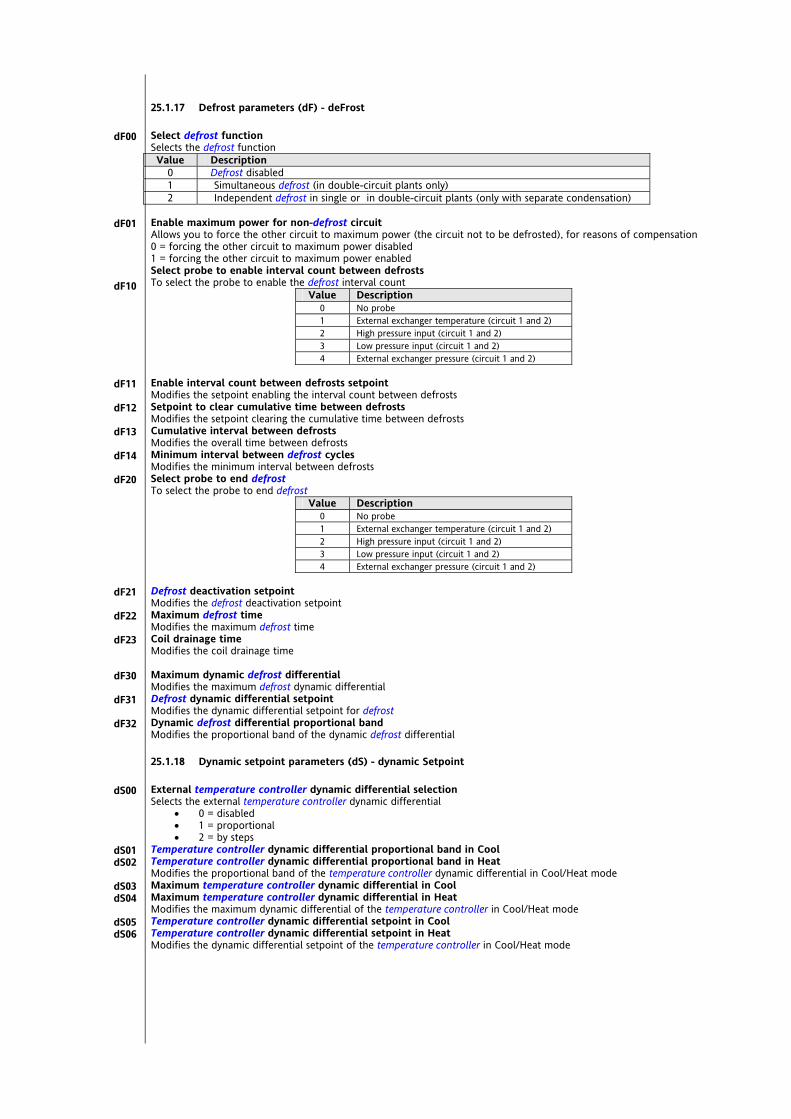
25.1.17 Defrost parameters (dF) - deFrost Select defrost function Selects the defrost function Value Description
0 Defrost disabled 1 Simultaneous defrost (in double-circuit plants only) 2 Independent defrost in single or in double-circuit plants (only with separate condensation)
Enable maximum power for non-defrost circuit Allows you to force the other circuit to maximum power (the circuit not to be defrosted), for reasons of compensation 0 = forcing the other circuit to maximum power disabled 1 = forcing the other circuit to maximum power enabled Select probe to enable interval count between defrosts To select the probe to enable the defrost interval count
Value Description 0 No probe 1 External exchanger temperature (circuit 1 and 2) 2 High pressure input (circuit 1 and 2) 3 Low pressure input (circuit 1 and 2) 4 External exchanger pressure (circuit 1 and 2)
Enable interval count between defrosts setpoint Modifies the setpoint enabling the interval count between defrosts Setpoint to clear cumulative time between defrosts Modifies the setpoint clearing the cumulative time between defrosts Cumulative interval between defrosts Modifies the overall time between defrosts Minimum interval between defrost cycles Modifies the minimum interval between defrosts Select probe to end defrost To select the probe to end defrost
Value Description 0 No probe 1 External exchanger temperature (circuit 1 and 2) 2 High pressure input (circuit 1 and 2) 3 Low pressure input (circuit 1 and 2) 4 External exchanger pressure (circuit 1 and 2)
Defrost deactivation setpoint Modifies the defrost deactivation setpoint Maximum defrost time Modifies the maximum defrost time Coil drainage time Modifies the coil drainage time Maximum dynamic defrost differential Modifies the maximum defrost dynamic differential Defrost dynamic differential setpoint Modifies the dynamic differential setpoint for defrost Dynamic defrost differential proportional band Modifies the proportional band of the dynamic defrost differential
25.1.18 Dynamic setpoint parameters (dS) - dynamic Setpoint External temperature controller dynamic differential selection Selects the external temperature controller dynamic differential
0 = disabled 1 = proportional 2 = by steps
Temperature controller dynamic differential proportional band in Cool Temperature controller dynamic differential proportional band in Heat Modifies the proportional band of the temperature controller dynamic differential in Cool/Heat mode Maximum temperature controller dynamic differential in Cool Maximum temperature controller dynamic differential in Heat Modifies the maximum dynamic differential of the temperature controller in Cool/Heat mode Temperature controller dynamic differential setpoint in Cool Temperature controller dynamic differential setpoint in Heat Modifies the dynamic differential setpoint of the temperature controller in Cool/Heat mode
dF00
dF01
dF10
dF11
dF12
dF13
dF14
dF20
dF21
dF22
dF23
dF30
dF31
dF32
dS00
dS01 dS02
dS03 dS04
dS05 dS06
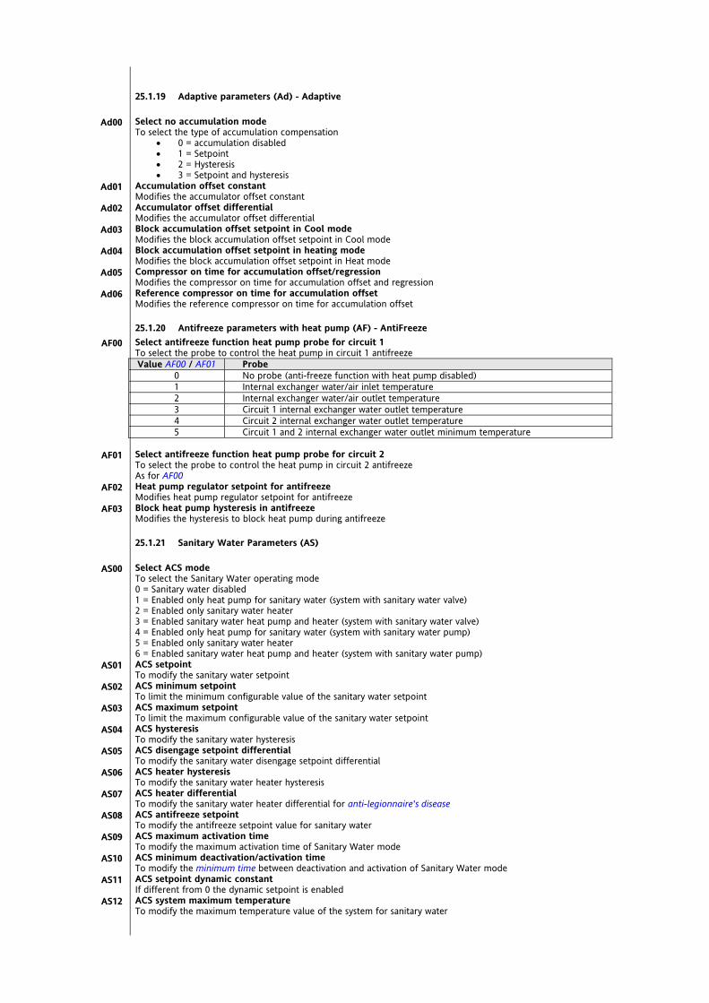
25.1.19 Adaptive parameters (Ad) - Adaptive Select no accumulation mode To select the type of accumulation compensation
0 = accumulation disabled 1 = Setpoint 2 = Hysteresis 3 = Setpoint and hysteresis
Accumulation offset constant Modifies the accumulator offset constant Accumulator offset differential Modifies the accumulator offset differential Block accumulation offset setpoint in Cool mode Modifies the block accumulation offset setpoint in Cool mode Block accumulation offset setpoint in heating mode Modifies the block accumulation offset setpoint in Heat mode Compressor on time for accumulation offset/regression Modifies the compressor on time for accumulation offset and regression Reference compressor on time for accumulation offset Modifies the reference compressor on time for accumulation offset
25.1.20 Antifreeze parameters with heat pump (AF) - AntiFreeze Select antifreeze function heat pump probe for circuit 1 To select the probe to control the heat pump in circuit 1 antifreeze Value AF00 / AF01 Probe
0 No probe (anti-freeze function with heat pump disabled) 1 Internal exchanger water/air inlet temperature 2 Internal exchanger water/air outlet temperature 3 Circuit 1 internal exchanger water outlet temperature 4 Circuit 2 internal exchanger water outlet temperature 5 Circuit 1 and 2 internal exchanger water outlet minimum temperature
Select antifreeze function heat pump probe for circuit 2 To select the probe to control the heat pump in circuit 2 antifreeze As for AF00 Heat pump regulator setpoint for antifreeze Modifies heat pump regulator setpoint for antifreeze Block heat pump hysteresis in antifreeze Modifies the hysteresis to block heat pump during antifreeze
25.1.21 Sanitary Water Parameters (AS) Select ACS mode To select the Sanitary Water operating mode 0 = Sanitary water disabled 1 = Enabled only heat pump for sanitary water (system with sanitary water valve) 2 = Enabled only sanitary water heater 3 = Enabled sanitary water heat pump and heater (system with sanitary water valve) 4 = Enabled only heat pump for sanitary water (system with sanitary water pump) 5 = Enabled only sanitary water heater 6 = Enabled sanitary water heat pump and heater (system with sanitary water pump) ACS setpoint To modify the sanitary water setpoint ACS minimum setpoint To limit the minimum configurable value of the sanitary water setpoint ACS maximum setpoint To limit the maximum configurable value of the sanitary water setpoint ACS hysteresis To modify the sanitary water hysteresis ACS disengage setpoint differential To modify the sanitary water disengage setpoint differential ACS heater hysteresis To modify the sanitary water heater hysteresis ACS heater differential To modify the sanitary water heater differential for anti-legionnaire's disease ACS antifreeze setpoint To modify the antifreeze setpoint value for sanitary water ACS maximum activation time To modify the maximum activation time of Sanitary Water mode ACS minimum deactivation/activation time To modify the minimum time between deactivation and activation of Sanitary Water mode ACS setpoint dynamic constant If different from 0 the dynamic setpoint is enabled ACS system maximum temperature To modify the maximum temperature value of the system for sanitary water
Ad00
Ad01
Ad02
Ad03
Ad04
Ad05
Ad06
AF00
AF01
AF02
AF03
AS00
AS01
AS02
AS03
AS04
AS05
AS06
AS07
AS08
AS09
AS10
AS11
AS12

ACS setpoint for anti-legionnaire's disease To limit the value of the sanitary water setpoint for anti-legionnaire's disease Minimum ACS setpoint for anti-legionnaire's disease To limit the minimum configurable value of setpoint AS20 - Sanitary water for anti-legionnaire's disease Maximum ACS setpoint for anti-legionnaire's disease To limit the maximum configurable value of setpoint AS20 - Sanitary water for anti-legionnaire's disease ACS minimum deactivation/activation time for anti-legionnaire's disease To modify the minimum time between deactivation and activation of Sanitary Water mode for anti-legionnaire's disease Anti-legionnaire's disease period, day 1 (Monday) In hours. 0=event disabled Event hour, day 1 (Monday) Determines the start time hour of the event [0…23] Event minutes, day 1 (Monday) Determines the start time minute of the event at a set hour [0…59] Anti-legionnaire's disease period, day 2 (Tuesday) In hours. 0=event disabled Event hour, day 2 (Tuesday) Determines the start time hour of the event [0…23] Event minutes, day 2 (Tuesday) Determines the start time minute of the event at a set hour [0…59] Anti-legionnaire's disease period, day 3 (Wednesday) In hours. 0=event disabled Event hour, day 3 (Wednesday) Determines the start time hour of the event [0…23] Event minutes, day 3 (Wednesday) Determines the start time minute of the event at a set hour [0…59] Anti-legionnaire's disease period, day 4 (Thursday) In hours. 0=event disabled Event hour, day 4 (Thursday) Determines the start time hour of the event [0…23] Event minutes, day 4 (Thursday) Determines the start time minute of the event at a set hour [0…59] Anti-legionnaire's disease period, day 5 (Friday) In hours. 0=event disabled Event hour, day 5 (Friday) Determines the start time hour of the event [0…23] Event minutes, day 5 (Friday) Determines the start time minute of the event at a set hour [0…59] Anti-legionnaire's disease period, day 6 (Saturday) In hours. 0=event disabled Event hour, day 6 (Saturday) Determines the start time hour of the event [0…23] Event minutes, day 6 (Saturday) Determines the start time minute of the event at a set hour [0…59] Anti-legionnaire's disease period, day 7 (Sunday) In hours. 0=event disabled Event hour, day 7 (Sunday) Determines the start time hour of the event [0…23] Event minutes, day 7 (Sunday) Determines the start time minute of the event at a set hour [0…59]
AS20
AS21
AS22
AS23
AS25
AS26
AS27
AS28
AS29
AS30
AS31
AS32
AS33
AS34
AS35
AS36
AS37
AS38
AS39
AS40
AS41
AS42
AS43
AS44
AS45

25.1.22 Heat pump block parameters (HP) - Heat Pump Select heat pump lock probe circuit 1 To select the probe to block the heat pump in circuit 1 antifreeze Value Probe Mode
0 No probe (block pump disabled) - 1 External temperature Heating 2 Internal exchanger water/air inlet temperature Cooling 3 Internal exchanger water/air outlet temperature Cooling 4 Circuit 1 and 2 internal exchanger water outlet average temperature Cooling 5 Recovery (or external) exchanger inlet water temperature Cooling 6 Recovery (or external) exchanger water outlet temperature Cooling 7 Circuit 1 and 2 external exchanger average temperature Cooling
Heat pump lock setpoint Sets the heat pump 1 regulator setpoint Boiler regulator hysteresis Modifies heat pump 1 regulator hysteresis Block heat pump 1 maximum differential Modifies the block heat pump differential circuit 1 Block heat pump circuit 1 differential setpoint Modifies the block heat pump differential setpoint circuit 1 Block heat pump proportional band circuit 1 Modifies the block heat pump proportional band circuit 1 Select heat pump lock probe circuit 2 To select the probe to block the heat pump in circuit 2 antifreeze As for HP00 Heat pump 2 lock setpoint Sets the heat pump 2 regulator setpoint Hysteresis Heat pump 2 lock Modifies heat pump 2 regulator hysteresis
HP00
HP01
HP02
HP03
HP04
HP05
HP10
HP11
HP12

25.1.23 Power limitation parameters (PL) - Power Limitation Power limitation on external temperature Power limitation on external temperature proportional band Modifies the proportional band for power limitation on external temperature External temperature setpoint for power limitation in Cool Modifies the external temperature setpoint for power limitation in Cool mode External temperature setpoint for power limitation in Heat Modifies the external temperature setpoint for power limitation in Heat mode Power limitation on temperature Power limitation on water/air temperature proportional band Modifies the proportional band for power limitation on temperature Select probe for power limitation on water/air temperature To select the probe for power limitation Value Probe
0 No probe (regulator disabled) 1 Internal exchanger water/air inlet temperature 2 Internal exchanger water/air outlet temperature 3 Circuit 1 and 2 internal exchanger water outlet average temperature 4 Recovery (or external) exchanger inlet water temperature 5 Recovery (or external) exchanger water outlet temperature 6 Circuit 1 and 2 external exchanger average temperature
High temperature setpoint for power limitation Modifies the high temperature setpoint for power limitation Low temperature setpoint for power limitation Modifies the low temperature setpoint for power limitation Power limitation on pressure Power limitation on pressure proportional band Modifies the proportional band for power limitation on pressure High pressure setpoint for power limitation Modifies the high pressure setpoint for power limitation Low pressure setpoint for power limitation Modifies the low pressure setpoint for power limitation
25.1.24 Time Band Parameters (tE) Enable time band operation To enable or disable time band operation 0= time bands disabled 1= time bands enabled Select profile, day 1 (Monday) To select the profile of the first day of the week
1= Profile 1 2= Profile 2 3= Profile 3
Select profile, day 2 (Tuesday) To select the profile of the second day of the week - See tE01 Select profile, day 3 (Wednesday) To select the profile of the third day of the week - See tE01 Select profile, day 4 (Thursday) To select the profile of the fourth day of the week - See tE01 Select profile, day 5 (Friday) To select the profile of the fifth day of the week - See tE01 Select profile, day 6 (Saturday) To select the profile of the sixth day of the week - See tE01 Select profile, day 7 (Sunday) To select the profile of the seventh day of the week - See tE01 PROFILE 1 EVENT 1 / PROFILE 1 Event start time hour 1, profile 1 Determines the start time hour of the event [0…23] Event start time minutes 1, profile 1 Determines the start time minute of the event at a set hour [0…59] Operating mode from event 1, profile 1 Determines the operating mode of Energy Flex during the event
0= ON 1 = Standby
Cool mode temperature regulator setpoint, from event 1, profile 1 Determines the Cool setpoint to use during the event (with Energy Flex in Cool mode) Heat mode temperature regulator setpoint, from event 1, profile 1 Determines the Heat setpoint to use during the event (with Energy Flex in Heat mode) ACS setpoint, from event 1, profile 1 Determines the Sanitary Water setpoint to use during the event
PL00
PL01
PL02
PL10
PL11
PL12
PL13
PL20
PL21
PL22
tE00
tE01
tE02
tE03
tE04
tE05
tE06
tE07
tE10
tE11
tE12
tE13
tE14
tE15
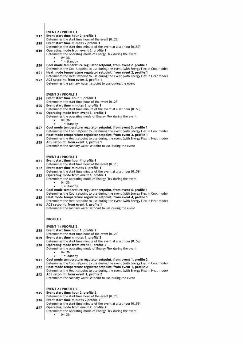
EVENT 2 / PROFILE 1 Event start time hour 2, profile 1 Determines the start time hour of the event [0…23] Event start time minutes 2 profile 1 Determines the start time minute of the event at a set hour [0…59] Operating mode from event 2, profile 1 Determines the operating mode of Energy Flex during the event
0= ON 1 = Standby
Cool mode temperature regulator setpoint, from event 2, profile 1 Determines the Cool setpoint to use during the event (with Energy Flex in Cool mode) Heat mode temperature regulator setpoint, from event 2, profile 1 Determines the Heat setpoint to use during the event (with Energy Flex in Heat mode) ACS setpoint, from event 2, profile 1 Determines the sanitary water setpoint to use during the event EVENT 3 / PROFILE 1 Event start time hour 3, profile 1 Determines the start time hour of the event [0…23] Event start time minutes 3, profile 1 Determines the start time minute of the event at a set hour [0…59] Operating mode from event 3, profile 1 Determines the operating mode of Energy Flex during the event
0= ON 1 = Standby
Cool mode temperature regulator setpoint, from event 3, profile 1 Determines the Cool setpoint to use during the event (with Energy Flex in Cool mode) Heat mode temperature regulator setpoint, from event 3, profile 1 Determines the Heat setpoint to use during the event (with Energy Flex in Heat mode) ACS setpoint, from event 3, profile 1 Determines the sanitary water setpoint to use during the event EVENT 4 / PROFILE 1 Event start time hour 4, profile 1 Determines the start time hour of the event [0…23] Event start time minutes 4, profile 1 Determines the start time minute of the event at a set hour [0…59] Operating mode from event 4, profile 1 Determines the operating mode of Energy Flex during the event
0= ON 1 = Standby
Cool mode temperature regulator setpoint, from event 4, profile 1 Determines the Cool setpoint to use during the event (with Energy Flex in Cool mode) Heat mode temperature regulator setpoint, from event 4, profile 1 Determines the Heat setpoint to use during the event (with Energy Flex in Heat mode) ACS setpoint, from event 4, profile 1 Determines the sanitary water setpoint to use during the event PROFILE 2 EVENT 1 / PROFILE 2 Event start time hour 1, profile 2 Determines the start time hour of the event [0…23] Event start time minutes 1, profile 2 Determines the start time minute of the event at a set hour [0…59] Operating mode from event 1, profile 2 Determines the operating mode of Energy Flex during the event
0= ON 1 = Standby
Cool mode temperature regulator setpoint, from event 1, profile 2 Determines the Cool setpoint to use during the event (with Energy Flex in Cool mode) Heat mode temperature regulator setpoint, from event 1, profile 2 Determines the Heat setpoint to use during the event (with Energy Flex in Heat mode) ACS setpoint, from event 1, profile 2 Determines the sanitary water setpoint to use during the event EVENT 2 / PROFILE 2 Event start time hour 2, profile 2 Determines the start time hour of the event [0…23] Event start time minutes 2 profile 2 Determines the start time minute of the event at a set hour [0…59] Operating mode from event 2, profile 2 Determines the operating mode of Energy Flex during the event
0= ON
tE17
tE18
tE19
tE20
tE21
tE22
tE24
tE25
tE26
tE27
tE28
tE29
tE31
tE32
tE33
tE34
tE35
tE36
tE38
tE39
tE40
tE41
tE42
tE43
tE45
tE46
tE47

1 = Standby Cool mode temperature regulator setpoint, from event 2, profile 2 Determines the Cool setpoint to use during the event (with Energy Flex in Cool mode) Heat mode temperature regulator setpoint, from event 2, profile 2 Determines the Heat setpoint to use during the event (with Energy Flex in Heat mode) ACS setpoint, from event 2, profile 2 Determines the sanitary water setpoint to use during the event EVENT 3 / PROFILE 2 Event start time hour 3, profile 2 Determines the start time hour of the event [0…23] Event start time minutes 3, profile 2 Determines the start time minute of the event at a set hour [0…59] Operating mode from event 3, profile 2 Determines the operating mode of Energy Flex during the event
0= ON 1 = Standby
Cool mode temperature regulator setpoint, from event 3, profile 2 Determines the Cool setpoint to use during the event (with Energy Flex in Cool mode) Heat mode temperature regulator setpoint, from event 3, profile 2 Determines the Heat setpoint to use during the event (with Energy Flex in Heat mode) ACS setpoint, from event 3, profile 2 Determines the sanitary water setpoint to use during the event EVENT 4 / PROFILE 2 Event start time hour 4, profile 2 Determines the start time hour of the event [0…23] Event start time minutes 4, profile 2 Determines the start time minute of the event at a set hour [0…59] Operating mode from event 4, profile 2 Determines the operating mode of Energy Flex during the event
0= ON 1 = Standby
Cool mode temperature regulator setpoint, from event 4, profile 2 Determines the Cool setpoint to use during the event (with Energy Flex in Cool mode) Heat mode temperature regulator setpoint, from event 4, profile 2 Determines the Heat setpoint to use during the event (with Energy Flex in Heat mode) ACS setpoint, from event 4, profile 2 Determines the sanitary water setpoint to use during the event PROFILE 3 EVENT 1 / PROFILE 3 Event start time hour 1, profile 3 Determines the start time hour of the event [0…23] Event start time minutes 1, profile 3 Determines the start time minute of the event at a set hour [0…59] Operating mode from event 1, profile 3 Determines the operating mode of Energy Flex during the event
0= ON 1 = Standby
Cool mode temperature regulator setpoint, from event 1, profile 3 Determines the Cool setpoint to use during the event (with Energy Flex in Cool mode) Heat mode temperature regulator setpoint, from event 1, profile 3 Determines the Heat setpoint to use during the event (with Energy Flex in Heat mode) ACS setpoint, from event 1, profile 3 Determines the sanitary water setpoint to use during the event EVENT 2 / PROFILE 3 Event start time hour 2, profile 3 Determines the start time hour of the event [0…23] Event start time minutes 2 profile 3 Determines the start time minute of the event at a set hour [0…59] Operating mode from event 2, profile 3 Determines the operating mode of Energy Flex during the event
0= ON 1 = Standby
Cool mode temperature regulator setpoint, from event 2, profile 3 Determines the Cool setpoint to use during the event (with Energy Flex in Cool mode) Heat mode temperature regulator setpoint, from event 2, profile 3 Determines the Heat setpoint to use during the event (with Energy Flex in Heat mode) ACS setpoint, from event 2, profile 3 Determines the sanitary water setpoint to use during the event EVENT 3 / PROFILE 3 Event start time hour 3, profile 3 Determines the start time hour of the event [0…23]
tE48
tE49
tE50
tE52
tE53
tE54
tE55
tE56
tE57
tE59
tE60
tE61
tE62
tE63
tE64
tE66
tE67
tE68
tE69
tE70
tE71
tE73
tE74
tE75
tE76
tE77
tE78
tE80

Event start time minutes 3, profile 3 Determines the start time minute of the event at a set hour [0…59] Operating mode from event 3, profile 3 Determines the operating mode of Energy Flex during the event
0= ON 1 = Standby
Cool mode temperature regulator setpoint, from event 3, profile 3 Determines the Cool setpoint to use during the event (with Energy Flex in Cool mode) Heat mode temperature regulator setpoint, from event 3, profile 3 Determines the Heat setpoint to use during the event (with Energy Flex in Heat mode) ACS setpoint, from event 3, profile 3 Determines the sanitary water setpoint to use during the event EVENT 4 / PROFILE 3 Event start time hour 4, profile 3 Determines the start time hour of the event [0…23] Event start time minutes 4, profile 3 Determines the start time minute of the event at a set hour [0…59] Operating mode from event 4, profile 3 Determines the operating mode of Energy Flex during the event
0= ON 1 = Standby
Cool mode temperature regulator setpoint, from event 4, profile 3 Determines the Cool setpoint to use during the event (with Energy Flex in Cool mode) Heat mode temperature regulator setpoint, from event 4, profile 3 Determines the Heat setpoint to use during the event (with Energy Flex in Heat mode) ACS setpoint, from event 4, profile 3 Determines the sanitary water setpoint to use during the event
tE81
tE82
tE83
tE84
tE85
tE87
tE88
tE89
tE90
tE91
tE92

25.1.25 Alarm parameters (AL) - ALarm Time interval for alarm event count Modifies the interval in which alarm events are counted AL00 is expressed in minutes. Alarms are counted every AL00/32 (minutes) = sample time. Maximum number of events in alarm log Modifies the maximum number of events stored in the alarm log DIGITAL ALARMS Number of high pressure alarms Modifies the number of high pressure alarms Low pressure alarm bypass time Modifies the low pressure alarm bypass time Number of low pressure alarms Modifies the number of low pressure alarms Enable low pressure alarm during defrost To enable or disable the low pressure alarm during defrost
0 = Alarm disabled 1 = Alarm enabled
Bypass flow switch time from activation of the internal circuit water pump Modifies the bypass flow switch time from activation of the internal circuit water pump Flow switch activation time for internal circuit automatic alarms Modifies the activation time of the flow switch for internal circuit automatic alarms Flow switch activation time for internal circuit manual alarm Modifies the activation time of the flow switch for internal circuit manual alarms Bypass flow switch time from activation of the external circuit water pump Modifies the flow switch bypass time from activation of the external circuit water pump Flow switch activation time for external circuit automatic alarms Modifies the activation time of the flow switch for external circuit automatic alarms Flow switch activation time for external circuit manual alarm Modifies the activation time of the flow switch for external circuit manual alarms Compressor thermal switch alarm bypass time Modifies the bypass time of the compressor thermal switch alarm Number of compressor thermal switch alarms Modifies the number of compressor thermal switch alarms Compressor oil pressure switch alarm bypass time Modifies the compressor oil pressure switch alarm bypass time Number of compressor oil pressure switch alarms Modifies the number of compressor oil pressure switch alarms Number of internal exchanger fan thermal switch alarms Modifies the number of internal exchanger fan thermal switch alarms Number of external exchanger fan thermal switch alarms Modifies the number of external exchanger fan thermal switch alarms Number of internal circuit pump thermoswitch alarms To modify the number of internal circuit pump thermoswitch alarms Number of external circuit pump thermoswitch alarms To modify the number of external circuit pump thermoswitch alarms ANALOGUE ALARMS High pressure alarm regulator setpoint from analogue input Modifies the setpoint of the high pressure alarm regulator from analogue input High pressure alarm regulator hysteresis from analogue input Modifies the hysteresis of the high pressure alarm regulator from analogue input Number of high pressure alarms from analogue input Modifies the number of high pressure alarms from analogue input Low pressure alarm bypass time from analogue input Modifies the low pressure alarm bypass time from analogue input Low pressure alarm regulator setpoint from analogue input Modifies the setpoint of the low pressure alarm regulator from analogue input Low pressure alarm regulator hysteresis from analogue input Modifies the setpoint of the low pressure alarm regulator hysteresis from analogue input Number of low pressure alarms from analogue input Modifies the number of low pressure alarms from analogue input High temperature alarm regulator setpoint from analogue input Modifies the setpoint of the high temperature alarm regulator from analogue input High temperature alarm regulator hysteresis from analogue input Modifies the hysteresis of the high temperature alarm regulator from analogue input High temperature delay before alarm Modifies the time temperature is high before alarm generated Internal circuit antifreeze alarm bypass time Modifies the internal circuit antifreeze alarm bypass time Internal circuit antifreeze alarm regulator setpoint Modifies the internal circuit antifreeze alarm regulator setpoint Internal circuit antifreeze alarm regulator hysteresis Modifies the internal circuit antifreeze alarm regulator hysteresis Number of internal circuit antifreeze alarms Modifies the number of internal circuit antifreeze alarms
AL00
AL01
AL10
AL11
AL12
AL13
AL14
AL15
AL16
AL17
AL18
AL19
AL20
AL21
AL22
AL23
AL24
AL25
AL26
AL27
AL40
AL41
AL42
AL43
AL44
AL45
AL46
AL47
AL48
AL49
AL50
AL51
AL52
AL53

External circuit antifreeze alarm bypass time Modifies the external circuit antifreeze alarm bypass time External circuit antifreeze alarm regulator setpoint Modifies the external circuit antifreeze alarm regulator setpoint External circuit antifreeze alarm regulator hysteresis Modifies the external circuit antifreeze alarm regulator hysteresis Number of external circuit antifreeze alarms Modifies the number of external circuit antifreeze alarms NO REFRIGERANT Enable low refrigerant alarm To enable or disable the low refrigerant alarm
0 = Low refrigerant alarm disabled 1 = Low refrigerant alarm enabled
Low refrigerant alarm bypass time Modifies the low refrigerant alarm bypass time Low refrigerant alarm differential Modifies the low refrigerant alarm differential Low refrigerant delay before alarm Modifies the time refrigerant is low before alarm generated MAINTENANCE Compressor start time for maintenance signal Modifies the on time of compressor for the service message Internal pump start time on maintenance signal Modifies the on time of pump for the service message External pump start time on maintenance signal Modifies the on time of pump for the service message
AL54
AL55
AL56
AL57
AL70
AL71
AL72
AL73
AL80
AL81
AL82
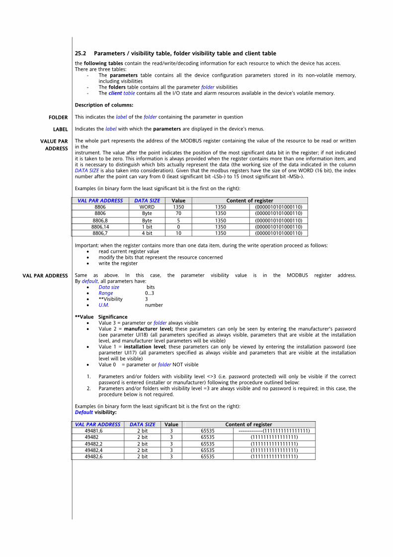
25.2 Parameters / visibility table, folder visibility table and client table the following tables contain the read/write/decoding information for each resource to which the device has access. There are three tables:
- The parameters table contains all the device configuration parameters stored in its non-volatile memory, including visibilities
- The folders table contains all the parameter folder visibilities - The client table contains all the I/O state and alarm resources available in the device’s volatile memory.
Description of columns: This indicates the label of the folder containing the parameter in question Indicates the label with which the parameters are displayed in the device’s menus. The whole part represents the address of the MODBUS register containing the value of the resource to be read or written in the instrument. The value after the point indicates the position of the most significant data bit in the register; if not indicated it is taken to be zero. This information is always provided when the register contains more than one information item, and it is necessary to distinguish which bits actually represent the data (the working size of the data indicated in the column DATA SIZE is also taken into consideration). Given that the modbus registers have the size of one WORD (16 bit), the index number after the point can vary from 0 (least significant bit -LSb-) to 15 (most significant bit -MSb-). Examples (in binary form the least significant bit is the first on the right): VAL PAR ADDRESS DATA SIZE Value Content of register
8806 WORD 1350 1350 (0000010101000110) 8806 Byte 70 1350 (0000010101000110)
8806,8 Byte 5 1350 (0000010101000110) 8806,14 1 bit 0 1350 (0000010101000110) 8806,7 4 bit 10 1350 (0000010101000110)
Important: when the register contains more than one data item, during the write operation proceed as follows:
read current register value modify the bits that represent the resource concerned write the register
Same as above. In this case, the parameter visibility value is in the MODBUS register address. By default, all parameters have:
Data size bits Range 0…3 **Visibility 3 U.M. number
**Value Significance
Value 3 = parameter or folder always visible Value 2 = manufacturer level; these parameters can only be seen by entering the manufacturer's password
(see parameter UI18) (all parameters specified as always visible, parameters that are visible at the installation level, and manufacturer level parameters will be visible)
Value 1 = installation level; these parameters can only be viewed by entering the installation password (see parameter UI17) (all parameters specified as always visible and parameters that are visible at the installation level will be visible)
Value 0 = parameter or folder NOT visible
1. Parameters and/or folders with visibility level <>3 (i.e. password protected) will only be visible if the correct password is entered (installer or manufacturer) following the procedure outlined below:
2. Parameters and/or folders with visibility level =3 are always visible and no password is required; in this case, the procedure below is not required.
Examples (in binary form the least significant bit is the first on the right): Default visibility: VAL PAR ADDRESS DATA SIZE Value Content of register
49481,6 2 bit 3 65535 -------------(1111111111111111) 49482 2 bit 3 65535 (1111111111111111) 49482,2 2 bit 3 65535 (1111111111111111) 49482,4 2 bit 3 65535 (1111111111111111) 49482,6 2 bit 3 65535 (1111111111111111)
FOLDER
LABEL
VALUE PAR ADDRESS
VAL PAR ADDRESS

Modifies the visibility value of parameter CL04 (address 49482.6) from 3 to 0 Visibility modified VAL PAR ADDRESS DATA SIZE Value Content of register
49481,6 2 bit 0 16383 (0011111111111111) Indicates whether the device MUST be rebooted after the modification.
Y=YES the device MUST be rebooted after the modification: N=NO the device DOESN'T need to be rebooted to modify the parameter
Example: ALL configuration parameters (folder CF) have a value of Y so that the device MUST ALWAYS BE REBOOTED AFTER MODIFICATION Indicates if resources are read/write, read-only or write-only: R Read-only resource W Write-only resource RW Read / write resource Indicates the size of the data in bits. WORD = 16 bit Bytes = 8 bit “n” bits = 0...15 bits depending on the value of “n” When the field indicates “Y”, the value read by the register requires conversion, because the value represents a number with a sign. In the other cases the value is always positive or null. To carry out conversion, proceed as follows:
if the value in the register is between 0 and 32767, the result is the value itself (zero and positive values) if the value in the register is between 32768 and 65535, the result is the value of the register - 65536 (negative
values) Describes the interval of values that can be assigned to the parameter. It can be correlated with other parameters in the controller (indicated with the parameter label). NOTE: If the actual value is outside the limits specified for the parameter itself (for example, because other parameters defining the limits in question have been varied), teh actual value is not displayed but rather the value of the limit in violation Indicates the factory setting for the standard model of the instrument. Then table considers the hardware model SBW646/C with 4 relays + TRIAC + 2 analogue outputs A01 AO2 PWM + 1 low voltage analogue output A03 If set to -1 the value read from the register must be divided by 10 (value/10) to convert to the values given in the column RANGE and DEFAULT with the unit of measure given in the column U.M., Example: parameter CL04 = 50.0. Column EXP = -1:
The value read by the device /DeviceManager is 50.0 The value read from the register is 500 --> 500/10 = 50.0
Measurement unit for values converted according to the rules indicated in the CPL and EXP columns.
25.2.1 Parameters / visibility table (see following page)
RESET (Y/N)
R/W
DATA SIZE
CPL
RANGE
DEFAULT
EXP
U.M.

Energy SB-SD-SCW600 168/240
FOLD
ER
LABE
L
VALU
E PA
R AD
DRE
SS
DAT
A SI
ZE
CPL
EXP
VIS
PAR
ADD
RESS
RESE
T (Y
/N)
R/W
DES
CRIP
TIO
N
RAN
GE
DEF
AULT
M.U
.
CL CL00 49208 BYTE 49435,4 Y RW AIL1 analogue input type 0 ... 2 0 num CL CL01 49209 BYTE 49435,6 Y RW AIL2 analogue input type 0 ... 2 0 num CL CL02 49210 BYTE 49436 Y RW AIL3 analogue input type 0 ... 6 0 num CL CL03 49211 BYTE 49436,2 Y RW AIL4 analogue input type 0 ... 6 0 num CL CL04 49212 BYTE 49436,4 Y RW AIL5 analogue input type 0 ... 2 0 num CL CL10 16450 WORD Y -1 49436,6 Y RW AIL3 analogue input fullscale value CL11 ... 999 500 °C/Bar CL CL11 16462 WORD Y -1 49437 Y RW AIL3 analogue input start of scale value -500 ... CL10 0.0 °C/Bar CL CL12 16452 WORD Y -1 49437,2 Y RW AIL4 analogue input fullscale value CL13 ... 999 500 °C/Bar CL CL13 16464 WORD Y -1 49437,4 Y RW AIL4 analogue input start of scale value -500 ... CL12 0 °C/Bar CL CL20 49238 BYTE Y -1 49437,6 Y RW AIL1 analogue input differential -120 ... 120 0 °C CL CL21 49239 BYTE Y -1 49438 Y RW AIL2 analogue input differential -120 ... 120 0 °C CL CL22 49240 BYTE Y -1 49438,2 Y RW AIL3 analogue input differential -120 ... 120 0 °C/Bar
CL CL23 49241 BYTE Y -1 49438,4 Y RW AIL4 analogue input differential -120 ... 120 0 °C/Bar
CL CL24 49242 BYTE Y -1 49438,6 Y RW AIL5 analogue input differential -120 ... 120 0 °C CL CL30 49286 BYTE 49439 Y RW AIL1 analogue input configuration 0 ... 16 0 num CL CL31 49287 BYTE 49439,2 Y RW AIL2 analogue input configuration 0 ... 16 0 num CL CL32 49288 BYTE 49439,4 Y RW AIL3 analogue input configuration 0 ... 30 0 num CL CL33 49289 BYTE 49439,6 Y RW AIL4 analogue input configuration 0 ... 30 0 num CL CL34 49290 BYTE 49440 Y RW AIL5 analogue input configuration 0 ... 16 0 num CL CL40 49292 BYTE Y 49440,2 Y RW DIL1 digital input configuration -58 ... 58 0 num CL CL41 49293 BYTE Y 49440,4 Y RW DIL2 digital input configuration -58 ... 58 0 num CL CL42 49294 BYTE Y 49440,6 Y RW DIL3 digital input configuration -58 ... 58 0 num CL CL43 49295 BYTE Y 49441 Y RW DIL4 digital input configuration -58 ... 58 0 num CL CL44 49296 BYTE Y 49441,2 Y RW DIL5 digital input configuration -58 ... 58 0 num CL CL45 49297 BYTE Y 49441,4 Y RW DIL6 digital input configuration -58 ... 58 0 num CL CL50 49302 BYTE Y 49442 Y RW AIL1 analogue input configuration 1 when configured as digital input -58 ... 58 0 num
CL CL51 49303 BYTE Y 49442,2 Y RW AIL2 analogue input configuration 2 when configured as digital input -58 ... 58 0 num
CL CL52 49304 BYTE Y 49442,4 Y RW AIL3 analogue input configuration 3 when configured as digital input -58 ... 58 0 num
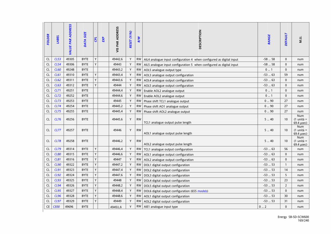
Energy SB-SD-SCW600 169/240
FOLD
ER
LABE
L
VALU
E PA
R AD
DRE
SS
DAT
A SI
ZE
CPL
EXP
VIS
PAR
ADD
RESS
RESE
T (Y
/N)
R/W
DES
CRIP
TIO
N
RAN
GE
DEF
AULT
M.U
.
CL CL53 49305 BYTE Y 49442,6 Y RW AIL4 analogue input configuration 4 when configured as digital input -58 ... 58 0 num CL CL54 49306 BYTE Y 49443 Y RW AIL5 analogue input configuration 5 when configured as digital input -58 ... 58 0 num CL CL60 49248 BYTE 49443,2 Y RW AOL5 analogue output type 0 ... 1 0 num CL CL61 49310 BYTE Y 49443,4 Y RW AOL3 analogue output configuration -53 ... 63 59 num CL CL62 49311 BYTE Y 49443,6 Y RW AOL4 analogue output configuration -53 ... 63 0 num CL CL63 49312 BYTE Y 49444 Y RW AOL5 analogue output configuration -53 ... 63 0 num CL CL71 49251 BYTE 49444,4 Y RW Enable AOL2 analogue output 0 ... 1 0 num CL CL72 49252 BYTE 49444,6 Y RW Enable AOL2 analogue output 0 ... 1 0 num CL CL73 49253 BYTE 49445 Y RW Phase shift TCL1 analogue output 0 ... 90 27 num CL CL74 49254 BYTE 49445,2 Y RW Phase shift AO1 analogue output 0 ... 90 27 num CL CL75 49255 BYTE 49445,4 Y RW Phase shift AOL2 analogue output 0 ... 90 27 num
CL CL76 49256 BYTE 49445,6 Y RW TCL1 analogue output pulse length
5 ... 40 10 Num
(1 unità = 69.4 μsec)
CL CL77 49257 BYTE 49446 Y RW AOL1 analogue output pulse length
5 ... 40 10 Num
(1 unità = 69.4 μsec)
CL CL78 49258 BYTE 49446,2 Y RW AOL2 analogue output pulse length
5 ... 40 10 Num
(1 unità = 69.4 μsec)
CL CL79 49314 BYTE Y 49446,4 Y RW TCL1 analogue output configuration -53 ... 63 56 num CL CL80 49315 BYTE Y 49446,6 Y RW AOL1 analogue output configuration -53 ... 63 0 num CL CL81 49316 BYTE Y 49447 Y RW AOL2 analogue output configuration -53 ... 63 0 num CL CL90 49322 BYTE Y 49447,2 Y RW DOL1 digital output configuration -53 ... 53 1 num CL CL91 49323 BYTE Y 49447,4 Y RW DOL2 digital output configuration -53 ... 53 14 num CL CL92 49324 BYTE Y 49447,6 Y RW DOL3 digital output configuration -53 ... 53 5 num CL CL93 49325 BYTE Y 49448 Y RW DOL4 digital output configuration -53 ... 53 23 num CL CL94 49326 BYTE Y 49448,2 Y RW DOL5 digital output configuration -53 ... 53 2 num CL CL95 49327 BYTE Y 49448,4 Y RW DOL6 digital output configuration (655 models) -53 ... 53 0 num CL CL96 49328 BYTE Y 49448,6 Y RW AOL1 digital output configuration -53 ... 53 30 num CL CL97 49329 BYTE Y 49449 Y RW AOL2 digital output configuration -53 ... 53 31 num
CE CE00 49696 BYTE 49451,6 Y RW AIE1 analogue input type 0 ... 2 0 num
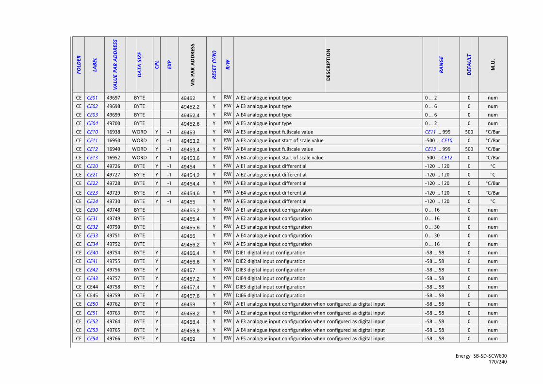
Energy SB-SD-SCW600 170/240
FOLD
ER
LABE
L
VALU
E PA
R AD
DRE
SS
DAT
A SI
ZE
CPL
EXP
VIS
PAR
ADD
RESS
RESE
T (Y
/N)
R/W
DES
CRIP
TIO
N
RAN
GE
DEF
AULT
M.U
.
CE CE01 49697 BYTE 49452 Y RW AIE2 analogue input type 0 ... 2 0 num CE CE02 49698 BYTE 49452,2 Y RW AIE3 analogue input type 0 ... 6 0 num CE CE03 49699 BYTE 49452,4 Y RW AIE4 analogue input type 0 ... 6 0 num CE CE04 49700 BYTE 49452,6 Y RW AIE5 analogue input type 0 ... 2 0 num CE CE10 16938 WORD Y -1 49453 Y RW AIE3 analogue input fullscale value CE11 ... 999 500 °C/Bar CE CE11 16950 WORD Y -1 49453,2 Y RW AIE3 analogue input start of scale value -500 ... CE10 0 °C/Bar CE CE12 16940 WORD Y -1 49453,4 Y RW AIE4 analogue input fullscale value CE13 ... 999 500 °C/Bar CE CE13 16952 WORD Y -1 49453,6 Y RW AIE4 analogue input start of scale value -500 ... CE12 0 °C/Bar CE CE20 49726 BYTE Y -1 49454 Y RW AIE1 analogue input differential -120 ... 120 0 °C CE CE21 49727 BYTE Y -1 49454,2 Y RW AIE2 analogue input differential -120 ... 120 0 °C CE CE22 49728 BYTE Y -1 49454,4 Y RW AIE3 analogue input differential -120 ... 120 0 °C/Bar
CE CE23 49729 BYTE Y -1 49454,6 Y RW AIE4 analogue input differential -120 ... 120 0 °C/Bar CE CE24 49730 BYTE Y -1 49455 Y RW AIE5 analogue input differential -120 ... 120 0 °C CE CE30 49748 BYTE 49455,2 Y RW AIE1 analogue input configuration 0 ... 16 0 num CE CE31 49749 BYTE 49455,4 Y RW AIE2 analogue input configuration 0 ... 16 0 num CE CE32 49750 BYTE 49455,6 Y RW AIE3 analogue input configuration 0 ... 30 0 num CE CE33 49751 BYTE 49456 Y RW AIE4 analogue input configuration 0 ... 30 0 num CE CE34 49752 BYTE 49456,2 Y RW AIE5 analogue input configuration 0 ... 16 0 num CE CE40 49754 BYTE Y 49456,4 Y RW DIE1 digital input configuration -58 ... 58 0 num CE CE41 49755 BYTE Y 49456,6 Y RW DIE2 digital input configuration -58 ... 58 0 num CE CE42 49756 BYTE Y 49457 Y RW DIE3 digital input configuration -58 ... 58 0 num CE CE43 49757 BYTE Y 49457,2 Y RW DIE4 digital input configuration -58 ... 58 0 num CE CE44 49758 BYTE Y 49457,4 Y RW DIE5 digital input configuration -58 ... 58 0 num CE CE45 49759 BYTE Y 49457,6 Y RW DIE6 digital input configuration -58 ... 58 0 num CE CE50 49762 BYTE Y 49458 Y RW AIE1 analogue input configuration when configured as digital input -58 ... 58 0 num
CE CE51 49763 BYTE Y 49458,2 Y RW AIE2 analogue input configuration when configured as digital input -58 ... 58 0 num CE CE52 49764 BYTE Y 49458,4 Y RW AIE3 analogue input configuration when configured as digital input -58 ... 58 0 num CE CE53 49765 BYTE Y 49458,6 Y RW AIE4 analogue input configuration when configured as digital input -58 ... 58 0 num CE CE54 49766 BYTE Y 49459 Y RW AIE5 analogue input configuration when configured as digital input -58 ... 58 0 num

Energy SB-SD-SCW600 171/240
FOLD
ER
LABE
L
VALU
E PA
R AD
DRE
SS
DAT
A SI
ZE
CPL
EXP
VIS
PAR
ADD
RESS
RESE
T (Y
/N)
R/W
DES
CRIP
TIO
N
RAN
GE
DEF
AULT
M.U
.
CE CE60 49736 BYTE 49459,2 Y RW AOE5 analogue output type 5 0 ... 1 0 num CE CE61 49768 BYTE Y 49459,4 Y RW AOE3 analogue output configuration -53 ... 63 0 num CE CE62 49769 BYTE Y 49459,6 Y RW AOE4 analogue output configuration -53 ... 63 0 num CE CE63 49770 BYTE Y 49460 Y RW AOE5 analogue output configuration -53 ... 63 0 num CE CE70 49738 BYTE 49460,2 Y RW Enable TCE1 analogue output 0 ... 1 1 num CE CE71 49739 BYTE 49460,4 Y RW Enable AOE1 analogue output 0 ... 1 0 num CE CE72 49740 BYTE 49460,6 Y RW Enable AOE2 analogue output 0 ... 1 0 num CE CE73 49741 BYTE 49461 Y RW Phase shift TCE1 analogue output 0 ... 90 27 Deg CE CE74 49742 BYTE 49461,2 Y RW Phase shift AOE1 analogue output 0 ... 90 27 Deg CE CE75 49743 BYTE 49461,4 Y RW Phase shift AOE2 analogue output 0 ... 90 27 Deg CE CE76 49744 BYTE 49461,6 Y RW TCE1 analogue output pulse length 5 ... 40 10 69 μsec CE CE77 49745 BYTE 49462 Y RW AOE1 analogue output pulse length 5 ... 40 10 69 μsec CE CE78 49746 BYTE 49462,2 Y RW AOE2 analogue output pulse length 5 ... 40 10 69 μsec CE CE79 49772 BYTE Y 49462,4 Y RW TCE1 analogue output configuration -53 ... 63 0 num CE CE80 49773 BYTE Y 49462,6 Y RW AOE1 analogue output configuration -53 ... 63 0 num CE CE81 49774 BYTE Y 49463 Y RW AOE2 analogue output configuration -53 ... 63 0 num CE CE90 49776 BYTE Y 49463,2 Y RW DOE1 digital output configuration -53 ... 53 0 num CE CE91 49777 BYTE Y 49463,4 Y RW DOE2 digital output configuration -53 ... 53 0 num CE CE92 49778 BYTE Y 49463,6 Y RW DOE3 digital output configuration -53 ... 53 0 num CE CE93 49779 BYTE Y 49464 Y RW DOE4 digital output configuration -53 ... 53 0 num CE CE94 49780 BYTE Y 49464,2 Y RW DOE5 digital output configuration -53 ... 53 0 num CE CE95 49781 BYTE Y 49464,4 Y RW DOE6 digital output configuration -53 ... 53 0 num CE CE96 49782 BYTE Y 49464,6 Y RW AOE1 digital output configuration -53 ... 53 0 num CE CE97 49783 BYTE Y 49465 Y RW AOE2 digital output configuration -53 ... 53 0 num Cr Cr00 49664 BYTE 49449,2 Y RW AIR1 analogue input type 0 ... 2 0 num Cr Cr01 49665 BYTE 49449,4 Y RW AIR2 analogue input type 0 ... 3 0 num Cr Cr10 16900 WORD Y -1 49449,6 Y RW AIR2 analogue input fullscale value Cr11 ... 999 0 num Cr Cr11 16904 WORD Y -1 49450 Y RW AIR2 analogue input start of scale value -999 ... Cr10 0 num Cr Cr20 49674 BYTE Y -1 49450,2 Y RW AIR1 analogue input differential -12.0 ... 12.0 0.0 °C
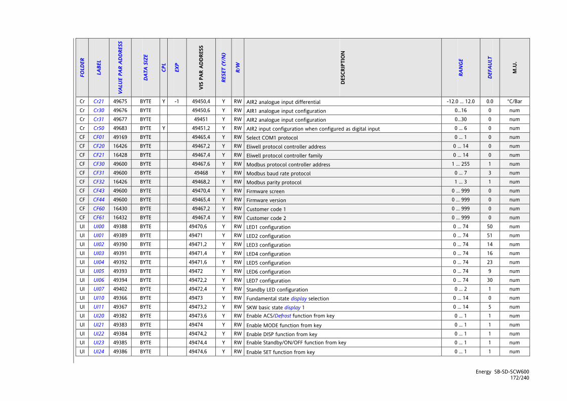
Energy SB-SD-SCW600 172/240
FOLD
ER
LABE
L
VALU
E PA
R AD
DRE
SS
DAT
A SI
ZE
CPL
EXP
VIS
PAR
ADD
RESS
RESE
T (Y
/N)
R/W
DES
CRIP
TIO
N
RAN
GE
DEF
AULT
M.U
.
Cr Cr21 49675 BYTE Y -1 49450,4 Y RW AIR2 analogue input differential -12.0 ... 12.0 0.0 °C/Bar Cr Cr30 49676 BYTE 49450,6 Y RW AIR1 analogue input configuration 0…16 0 num Cr Cr31 49677 BYTE 49451 Y RW AIR2 analogue input configuration 0…30 0 num Cr Cr50 49683 BYTE Y 49451,2 Y RW AIR2 input configuration when configured as digital input 0 ... 6 0 num CF CF01 49169 BYTE 49465,4 Y RW Select COM1 protocol 0 ... 1 0 num CF CF20 16426 BYTE 49467,2 Y RW Eliwell protocol controller address 0 ... 14 0 num CF CF21 16428 BYTE 49467,4 Y RW Eliwell protocol controller family 0 ... 14 0 num CF CF30 49600 BYTE 49467,6 Y RW Modbus protocol controller address 1 ... 255 1 num CF CF31 49600 BYTE 49468 Y RW Modbus baud rate protocol 0 ... 7 3 num CF CF32 16426 BYTE 49468,2 Y RW Modbus parity protocol 1 ... 3 1 num CF CF43 49600 BYTE 49470,4 Y RW Firmware screen 0 ... 999 0 num CF CF44 49600 BYTE 49465,4 Y RW Firmware version 0 ... 999 0 num CF CF60 16430 BYTE 49467,2 Y RW Customer code 1 0 ... 999 0 num CF CF61 16432 BYTE 49467,4 Y RW Customer code 2 0 ... 999 0 num UI UI00 49388 BYTE 49470,6 Y RW LED1 configuration 0 ... 74 50 num UI UI01 49389 BYTE 49471 Y RW LED2 configuration 0 ... 74 51 num UI UI02 49390 BYTE 49471,2 Y RW LED3 configuration 0 ... 74 14 num UI UI03 49391 BYTE 49471,4 Y RW LED4 configuration 0 ... 74 16 num UI UI04 49392 BYTE 49471,6 Y RW LED5 configuration 0 ... 74 23 num UI UI05 49393 BYTE 49472 Y RW LED6 configuration 0 ... 74 9 num UI UI06 49394 BYTE 49472,2 Y RW LED7 configuration 0 ... 74 30 num UI UI07 49402 BYTE 49472,4 Y RW Standby LED configuration 0 ... 2 1 num UI UI10 49366 BYTE 49473 Y RW Fundamental state display selection 0 ... 14 0 num UI UI11 49367 BYTE 49473,2 Y RW SKW basic state display 1 0 ... 14 5 num UI UI20 49382 BYTE 49473,6 Y RW Enable ACS/Defrost function from key 0 ... 1 1 num UI UI21 49383 BYTE 49474 Y RW Enable MODE function from key 0 ... 1 1 num UI UI22 49384 BYTE 49474,2 Y RW Enable DISP function from key 0 ... 1 1 num UI UI23 49385 BYTE 49474,4 Y RW Enable Standby/ON/OFF function from key 0 ... 1 1 num UI UI24 49386 BYTE 49474,6 Y RW Enable SET function from key 0 ... 1 1 num

Energy SB-SD-SCW600 173/240
FOLD
ER
LABE
L
VALU
E PA
R AD
DRE
SS
DAT
A SI
ZE
CPL
EXP
VIS
PAR
ADD
RESS
RESE
T (Y
/N)
R/W
DES
CRIP
TIO
N
RAN
GE
DEF
AULT
M.U
.
UI UI25 49387 BYTE 49475 Y RW Setpoint edit function enable from main screen 0 ... 1 0 num UI UI27 16640 WORD 49475,4 Y RW Installation engineer password 0 ... 255 1 num UI UI28 16642 WORD 49475,6 Y RW Manufacturer password 0 ... 255 2 num UI UI30 49395 BYTE 49476 Y RW LED11 configuration 0 ... 74 50 num UI UI31 49396 BYTE 49476,2 Y RW LED12 configuration 0 ... 74 51 num UI UI32 49397 BYTE 49476,4 Y RW LED13 configuration 0 ... 74 0 num UI UI33 49398 BYTE 49476,6 Y RW LED14 configuration 0 ... 74 0 num UI UI34 49399 BYTE 49477 Y RW LED15 configuration 0 ... 74 23 num UI UI35 49400 BYTE 49477,2 Y RW LED16 configuration 0 ... 74 0 num UI UI36 49401 BYTE 49477,4 Y RW LED17 configuration 0 ... 74 14 num tr tr00 49824 BYTE 49477,6 Y RW Temperature control type 0 ... 4 0 Num tr tr01 49825 BYTE 49478 Y RW Enable heating pump 0 ... 1 1 Num tr tr02 49826 BYTE 49478,2 Y RW Select temperature control probe in Cool 0 ... 5 0 Num tr tr03 49827 BYTE 49478,4 Y RW Select temperature control probe in Heat 0 ... 5 1 Num tr tr04 49828 BYTE 49478,6 Y RW Select probes for temperature control differential in Cool 0 ... 5 0 Num tr tr05 49829 BYTE 49479 Y RW Select probes for temperature control differential in Heat 0 ... 5 0 Num tr tr10 17062 WORD Y -1 49479,2 N RW Temperature control setpoint in Cool tr11 ... tr12 120 °C tr tr11 17064 WORD Y -1 49479,4 Y RW Minimum temperature control setpoint in Cool -500 ... tr12 110 °C
tr tr12 17066 WORD Y -1 49479,6 Y RW Maximum temperature control setpoint in Cool tr11 ... 999 200 °C
tr tr13 17068 WORD -1 49480 N RW Temperature control hysteresis in Cool 1 ... 255 30 °C
tr tr14 17070 WORD -1 49480,2 N RW Insert steps/compressors differential in Cool 1 ... 255 30 °C
tr tr15 17072 WORD Y -1 49480,4 N RW Setpoint differential in Cool from Economy input -255 ... 255 50 °C
tr tr20 17074 WORD Y -1 49480,6 N RW Temperature control setpoint in Heat tr21 ...tr22 400 °C
tr tr21 17076 WORD Y -1 49481 Y RW Minimum temperature control setpoint in Heat -500 ... tr22 300 °C
tr tr22 17078 WORD Y -1 49481,2 Y RW Maximum temperature control setpoint in Heat tr21 ... 999 450 °C
tr tr23 17080 WORD -1 49481,4 N RW Temperature control hysteresis in Heat 1 ... 255 30 °C
tr tr24 17082 WORD -1 49481,6 N RW Insert steps/compressors differential in Heat 1 ... 255 30 °C

Energy SB-SD-SCW600 174/240
FOLD
ER
LABE
L
VALU
E PA
R AD
DRE
SS
DAT
A SI
ZE
CPL
EXP
VIS
PAR
ADD
RESS
RESE
T (Y
/N)
R/W
DES
CRIP
TIO
N
RAN
GE
DEF
AULT
M.U
.
tr tr25 17084 WORD Y -1 49482 N RW Setpoint differential in Heat from Economy Input -255 ... 255 -50 °C tr tr30 17712 WORD -1 49482,4 Y RW Temperature controller hysteresis with inverter in Cool 0 ... 255 20 °C tr tr31 17714 WORD -1 49482,6 Y RW Temperature controller band with inverter in Cool 0 ... 255 30 °C tr tr32 50484 BYTE 49483 Y RW Minimum speed with inverter in Cool 0 ... tr33 20 num tr tr33 50485 BYTE 49483,2 Y RW Maximum speed with inverter in Cool tr32 ... 100 100 num tr tr34 17718 WORD -1 49483,4 Y RW Insert Inverters/compressors differential in Cool 0 ... 255 60 °C tr tr40 17726 WORD -1 49483,6 Y RW Temperature controller hysteresis with inverter in Heat 0 ... 255 20 °C tr tr41 17728 WORD -1 49484 Y RW Temperature controller band with inverter in Heat 0 ... 255 30 °C tr tr42 50498 BYTE 49484,2 Y RW Minimum speed with inverter in Heat 0 ... tr43 20 num tr tr43 50499 BYTE 49484,4 Y RW Maximum speed with inverter in Heat tr42 ... 100 100 num tr tr44 17732 WORD -1 49484,6 Y RW Insert Inverters/compressors differential in Heat 0 ... 255 0 °C St St00 49808 BYTE 49482,2 Y RW Select operating mode 0 ... 2 2 num St St01 49809 BYTE 49482,4 Y RW Enable change mode from analogue input 0 ... 1 0 num St St02 49810 BYTE 49482,6 Y RW Select probe to change automatic mode 0 ... 2 0 num St St03 17044 WORD Y -1 49483 N RW Differential for change automatic mode in Heat -25.5 ... 25.5 -10.0 °C St St04 17046 WORD Y -1 49483,2 N RW Differential for change automatic mode in Cool -25.5 ... 25.5 10.0 °C
St St05 49816 BYTE 49483,4 Y RW Reversal valve switching delay 0 ... 255 3 Sec
CP CP00 49886 BYTE 49483,6 Y RW Type of compressor 0 ... 2 0 num CP CP01 49887 BYTE 49484 Y RW Number of circuits 1 ... 2 1 num CP CP02 49888 BYTE 49484,2 Y RW Number of compressors per circuit 1 ... 4 2 num CP CP03 49889 BYTE 49484,4 Y RW Number of capacity steps of compressor 0 ... 3 0 num
CP CP10 49896 BYTE 49485,2 Y RW Enable circuit balancing 0 ... 1 0 Num
CP CP11 49897 BYTE 49485,4 Y RW Enable compressor balancing 0 ... 1 0 Num
CP CP12 49898 BYTE 49485,6 Y RW Circuit selection criterion 0 ... 1 0 Num
CP CP13 49899 BYTE 49486 Y RW Compressor selection criterion 0 ... 2 0 Num
CP CP14 17132 WORD 49486,2 Y RW Compressor operating time for each on sequence 0 ... 255 18 Sec*10
CP CP20 17136 WORD 49486,4 Y RW Minimum off/on for same compressor 0 ... 255 18 Sec*10 CP CP21 17138 WORD 49486,6 Y RW Minimum on/on time for same compressor 0 ... 255 30 Sec*10 CP CP22 17140 WORD 49487 Y RW Minimum compressor on time 0 ... 255 2 Sec*10

Energy SB-SD-SCW600 175/240
FOLD
ER
LABE
L
VALU
E PA
R AD
DRE
SS
DAT
A SI
ZE
CPL
EXP
VIS
PAR
ADD
RESS
RESE
T (Y
/N)
R/W
DES
CRIP
TIO
N
RAN
GE
DEF
AULT
M.U
.
CP CP23 17142 WORD 49487,2 Y RW Minimum on/on time for different compressors 1 ... 255 10 Sec
CP CP24 17144 WORD 49487,4 Y RW Minimum off/off time for different compressors 1 ... 255 10 Sec
CP CP25 17146 WORD 49487,6 Y RW Minimum compressor on time per splitting increment 1 ... 255 10 Sec CP CP26 17148 WORD 49488 Y RW Minimum compressor on time per splitting decrease 1 ... 255 5 Sec
CP CP27 17150 WORD 49488,2 Y RW Defrost compressor/step delay minimum 1 ... 255 3 Sec
PI PI00 49984 BYTE 49491,4 Y RW Select primary circuit water pump function 0 ... 2 2 Num
PI PI01 49985 BYTE 49491,6 Y RW Time primary circuit water pump not active for anti-lock 0 ... 255 50 h
PI PI02 49986 BYTE 49492 Y RW Internal circuit water pump pick-up time 0 ... 255 2 Sec
PI PI03 49987 BYTE 49492,2 Y RW Minimum internal circuit water pump start time 0 ... 255 10 Sec*10
PI PI05 49989 BYTE 49492,6 Y RW Maximum internal circuit water pump changeover start time 0 ... 255 0 h
PI PI10 49992 BYTE 49493 Y RW Enable primary circuit water pump on when anti-freeze heaters on 0 ... 1 0 Num
PI PI11 49993 BYTE 49493,2 Y RW Enable internal circuit special water pump 0 ... 2 1 Num
PI PI20 49996 BYTE Y -1 49493,4 Y RW Delay primary circuit water pump on - compressor on 0 ... 255 60 Sec
PI PI21 49997 BYTE Y -1 49493,6 Y RW Delay compressor off - primary circuit water pump off 0 ... 255 60 Sec
PI PI22 49998 BYTE 49494 Y RW Internal circuit pump periodic activation interval 0 ... 255 30 Min
PI PI30 50002 BYTE 49494,2 Y RW Minimum primary circuit water pump speed in Cool 0 ... 100 30 % PI PI31 50003 BYTE 49494,4 Y RW Maximum primary circuit water pump speed in Cool 0 ... 100 100 %
PI PI32 17236 WORD 49494,6 N RW Minimum primary circuit water pump setpoint speed in Cool -500 ... 999 200 °C
PI PI33 17238 WORD 49495 N RW Proportional band primary circuit water pump in Cool -255 ... 255 80 °C
PI PI34 50008 BYTE 49495,2 N RW Fan speed setpoint for primary circuit water pump modulation in cool 0 ... 100 80 %
PI PI35 50009 BYTE 49495,4 N RW Fan speed hysteresis for primary circuit water pump modulation in Cool 1 ... 100 10 %
PI PI40 50012 BYTE 49495,6 Y RW Minimum primary circuit water pump speed in Heat 0 ... 100 30 % PI PI41 50013 WORD 49496 Y RW Maximum primary circuit water pump speed in Heat 0 ... 100 100 % PI PI42 17246 WORD 49496,2 N RW Minimum primary circuit water pump setpoint speed in Heat -500 ... 999 200 °C
PI PI43 17248 BYTE 49496,4 N RW Proportional band primary circuit water pump in Heat -255 ... 255 180 °C
PI PI44 50018 BYTE 49496,6 N RW Fan speed setpoint for primary circuit water pump modulation in Heat 0 ... 100 80 %
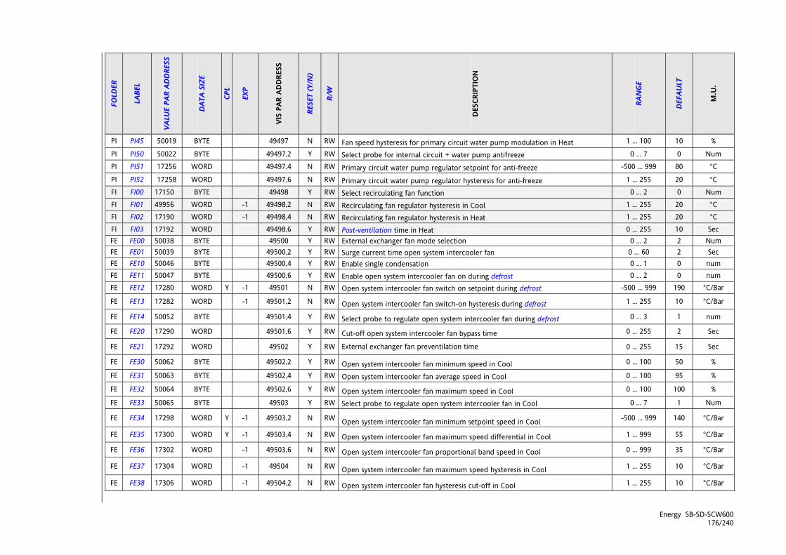
Energy SB-SD-SCW600 176/240
FOLD
ER
LABE
L
VALU
E PA
R AD
DRE
SS
DAT
A SI
ZE
CPL
EXP
VIS
PAR
ADD
RESS
RESE
T (Y
/N)
R/W
DES
CRIP
TIO
N
RAN
GE
DEF
AULT
M.U
.
PI PI45 50019 BYTE 49497 N RW Fan speed hysteresis for primary circuit water pump modulation in Heat 1 ... 100 10 %
PI PI50 50022 BYTE 49497,2 Y RW Select probe for internal circuit + water pump antifreeze 0 ... 7 0 Num
PI PI51 17256 WORD 49497,4 N RW Primary circuit water pump regulator setpoint for anti-freeze -500 ... 999 80 °C
PI PI52 17258 WORD 49497,6 N RW Primary circuit water pump regulator hysteresis for anti-freeze 1 ... 255 20 °C
FI FI00 17150 BYTE 49498 Y RW Select recirculating fan function 0 ... 2 0 Num FI FI01 49956 WORD -1 49498,2 N RW Recirculating fan regulator hysteresis in Cool 1 ... 255 20 °C FI FI02 17190 WORD -1 49498,4 N RW Recirculating fan regulator hysteresis in Heat 1 ... 255 20 °C FI FI03 17192 WORD 49498,6 Y RW Post-ventilation time in Heat 0 ... 255 10 Sec FE FE00 50038 BYTE 49500 Y RW External exchanger fan mode selection 0 ... 2 2 Num FE FE01 50039 BYTE 49500,2 Y RW Surge current time open system intercooler fan 0 ... 60 2 Sec FE FE10 50046 BYTE 49500,4 Y RW Enable single condensation 0 ... 1 0 num FE FE11 50047 BYTE 49500,6 Y RW Enable open system intercooler fan on during defrost 0 ... 2 0 num FE FE12 17280 WORD Y -1 49501 N RW Open system intercooler fan switch on setpoint during defrost -500 ... 999 190 °C/Bar
FE FE13 17282 WORD -1 49501,2 N RW Open system intercooler fan switch-on hysteresis during defrost 1 ... 255 10 °C/Bar
FE FE14 50052 BYTE 49501,4 Y RW Select probe to regulate open system intercooler fan during defrost 0 ... 3 1 num
FE FE20 17290 WORD 49501,6 Y RW Cut-off open system intercooler fan bypass time 0 ... 255 2 Sec
FE FE21 17292 WORD 49502 Y RW External exchanger fan preventilation time 0 ... 255 15 Sec
FE FE30 50062 BYTE 49502,2 Y RW Open system intercooler fan minimum speed in Cool 0 ... 100 50 %
FE FE31 50063 BYTE 49502,4 Y RW Open system intercooler fan average speed in Cool 0 ... 100 95 %
FE FE32 50064 BYTE 49502,6 Y RW Open system intercooler fan maximum speed in Cool 0 ... 100 100 %
FE FE33 50065 BYTE 49503 Y RW Select probe to regulate open system intercooler fan in Cool 0 ... 7 1 Num
FE FE34 17298 WORD Y -1 49503,2 N RW Open system intercooler fan minimum setpoint speed in Cool -500 ... 999 140 °C/Bar
FE FE35 17300 WORD Y -1 49503,4 N RW Open system intercooler fan maximum speed differential in Cool 1 ... 999 55 °C/Bar
FE FE36 17302 WORD -1 49503,6 N RW Open system intercooler fan proportional band speed in Cool 0 ... 999 35 °C/Bar
FE FE37 17304 WORD -1 49504 N RW Open system intercooler fan maximum speed hysteresis in Cool 1 ... 255 10 °C/Bar
FE FE38 17306 WORD -1 49504,2 N RW Open system intercooler fan hysteresis cut-off in Cool 1 ... 255 10 °C/Bar

Energy SB-SD-SCW600 177/240
FOLD
ER
LABE
L
VALU
E PA
R AD
DRE
SS
DAT
A SI
ZE
CPL
EXP
VIS
PAR
ADD
RESS
RESE
T (Y
/N)
R/W
DES
CRIP
TIO
N
RAN
GE
DEF
AULT
M.U
.
FE FE39 17308 WORD -1 49504,4 N RW Open system intercooler fan differential cut-off in Cool 0 ... 255 20 °C/Bar
FE FE50 50082 BYTE 49504,6 Y RW Open system intercooler fan minimum speed in Heat 0 ... 100 50 %
FE FE51 50083 BYTE 49505 Y RW Open system intercooler fan average speed in Heat 0 ... 100 95 % FE FE52 50084 BYTE 49505,2 Y RW Open system intercooler fan maximum speed in Heat 0 ... 100 100 % FE FE53 50085 BYTE 49505,4 Y RW Select probe to regulate open system intercooler fan in Heat 0 ... 7 1 Num
FE FE54 17318 WORD Y -1 49505,6 N RW Open system intercooler fan minimum setpoint speed in Heat -500 ... 999 55 °C/Bar
FE FE55 17320 WORD Y -1 49506 N RW Open system intercooler fan maximum speed differential in Heat 1 ... 999 17 °C/Bar
FE FE56 17322 WORD -1 49506,2 N RW Open system intercooler fan proportional band speed in Heat 0 ... 999 10 °C/Bar
FE FE57 17324 WORD -1 49506,4 N RW Open system intercooler fan maximum speed hysteresis in Heat 1 ... 255 5 °C/Bar
FE FE58 17326 WORD -1 49506,6 N RW Open system intercooler fan hysteresis cut-off in Heat 1 ... 255 5 °C/Bar
FE FE59 17328 WORD -1 49507 N RW Open system intercooler fan differential cut-off in Heat 0 ... 255 10 °C/Bar
PE PE00 50110 BYTE 49507,2 Y RW External circuit water pump mode selection 0 ... 3 0 num
HI HI00 50126 BYTE 49507,4 Y RW Enable internal exchanger antifreeze heaters in standby 0 ... 1 0 Num
HI HI01 50127 BYTE 49507,6 Y RW Enable force heaters on during defrost 0 ... 3 0 Num
HI HI10 50130 BYTE 49508 Y RW Select probe for antifreeze internal exchanger + heater 1 0 ... 3 2 Num
HI HI11 50131 BYTE 49508,2 Y RW Select probe for antifreeze internal exchanger + heater 2 0 ... 3 2 num
HI HI12 17364 WORD Y -1 49508,4 N RW Primary intercooler heaters regulator setpoint for anti-freeze Hi14 ... Hi13 40 °C
HI HI13 17366 WORD Y -1 49508,6 Y RW Primary intercooler heaters regulator maximum setpoint for anti-freeze Hi14 ... 999 70 °C
HI HI14 17368 WORD Y -1 49509 Y RW Primary intercooler heaters regulator minimum setpoint for anti-freeze -500 ... Hi13 -100 °C
HI HI15 17370 WORD -1 49509,2 N RW Primary intercooler heaters regulator hysteresis for anti-freeze 1 ... 255 5 °C
HI HI20 50146 BYTE 49509,4 Y RW Select heater mode for internal exchanger in integration mode 0 ... 3 0 Num
HI HI21 17380 WORD Y -1 49509,6 N RW Primary intercooler heaters dynamic differential setpoint in integration -500 ... 999 100 °C
HI HI22 17382 WORD -1 49510 Y RW Primary intercooler heaters maximum dynamic differential in integration 0 ... 999 255 °C
HI HI23 17384 WORD -1 49510,2 N RW Heater differential in integration mode with heat pump lock 0 ... 999 0 °C

Energy SB-SD-SCW600 178/240
FOLD
ER
LABE
L
VALU
E PA
R AD
DRE
SS
DAT
A SI
ZE
CPL
EXP
VIS
PAR
ADD
RESS
RESE
T (Y
/N)
R/W
DES
CRIP
TIO
N
RAN
GE
DEF
AULT
M.U
.
HI HI24 17386 WORD -1 49510,4 N RW Primary intercooler heaters dynamic differential proportional band in integration 0 ... 999 50 °C
HI HI25 17388 WORD -1 49510,6 N RW Primary intercooler heaters regulator hysteresis in integration 1 ... 255 10 °C
HI HI26 17390 WORD -1 49511 N RW Primary intercooler heater 2 switch-on setpoint differential in integration 0 ... 999 30 °C
HE HE00 50166 BYTE 49511,2 Y RW Enable external exchanger antifreeze heaters in standby 0 ... 1 0 Num
HE HE10 50168 BYTE 49511,4 Y RW Select probe for antifreeze external exchanger + heater 1 0 ... 4 0 Num
HE HE11 50169 BYTE 49511,6 Y RW Select probe for antifreeze external exchanger + heater 2 0 ... 4 0 num
HE HE12 17402 WORD Y -1 49512 N RW Open-system intercooler heaters switch-on setpoint for anti-freeze HE14 ...HE13 40 °C
HE HE13 17404 WORD Y -1 49512,2 Y RW Primary open-system intercooler heaters regulator maximum setpoint for anti-freeze
HE14 ... 999 70 °C
HE HE14 17406 WORD Y -1 49512,4 Y RW Primary open-system intercooler heaters regulator minimum setpoint for anti-freeze
-500 ... HE13 -100 °C
HE HE15 17408 WORD Y -1 49512,6 N RW Open-system intercooler heaters regulator hysteresis for anti-freeze 1 ... 255 10 °C
HA HA00 50186 BYTE 49513 Y RW Select probe for auxiliary output regulator 0 ... 6 0 Num HA HA01 17420 WORD Y -1 49513,2 N RW Auxiliary output regulator setpoint -500 ... 999 20 °C HA HA02 17422 WORD Y -1 49513,4 N RW Auxiliary output regulator hysteresis -500 ... 999 10 °C br br00 50200 BYTE 49513,6 Y RW Select boiler mode 0 ... 3 0 Num br br01 17434 WORD Y -1 49514 N RW Boiler dynamic differential setpoint -500 ... 999 100 °C br br02 17436 WORD -1 49514,2 Y RW Maximum boiler dynamic differential 0 ... 999 255 °C br br03 17438 WORD -1 49514,4 Y RW Boiler dynamic differential with heat pump lock 0 ... 999 0 °C
br br04 17440 WORD -1 49514,6 N RW Boiler proportional band dynamic differential 0 ... 999 50 °C
br br05 17442 WORD -1 49515 N RW Boiler regulator hysteresis 1 ... 255 20 °C dF dF00 50262 BYTE 49519 Y RW Select defrost mode 0 ... 2 2 num dF dF01 50263 BYTE 49519,2 Y RW Enable maximum power for non-defrost circuit 0 ... 1 0 num
dF dF10 50266 BYTE 49519,4 Y RW Select probe to enable interval count between defrost cycles 0 ... 4 1 Num
dF dF11 17500 WORD Y -1 49519,6 N RW Setpoint for enable interval count between defrost cycles -500 ... 999 25 °C / Bar dF dF12 17502 WORD Y -1 49520 N RW Setpoint to clear cumulative time between defrost cycles -500 ... 999 130 °C / Bar
dF dF13 17504 WORD 49520,2 Y RW Cumulative time between defrost cycles 1 ... 255 20 Min
dF dF14 17506 WORD 49520,4 Y RW Minimum interval between defrost cycles 1 ... 255 60 Min

Energy SB-SD-SCW600 179/240
FOLD
ER
LABE
L
VALU
E PA
R AD
DRE
SS
DAT
A SI
ZE
CPL
EXP
VIS
PAR
ADD
RESS
RESE
T (Y
/N)
R/W
DES
CRIP
TIO
N
RAN
GE
DEF
AULT
M.U
.
dF dF20 50280 BYTE 49520,6 Y RW Select probe to disable defrost 0 ... 4 1 Num dF dF21 17514 WORD Y -1 49521 N RW Disable defrost setpoint -500 ... 999 130 °C / Bar dF dF22 17516 WORD 49521,2 Y RW Maximum defrost time 1 ... 255 5 Min dF dF23 17518 WORD 49521,4 Y RW Drip time 0 ... 255 40 sec dF dF30 17524 WORD Y -1 49521,6 Y RW Maximum dynamic defrost differential -500 ... 999 0 °C / Bar
dF dF31 17526 WORD Y -1 49522 N RW Dynamic defrost differential setpoint -500 ... 999 100 °C
dF dF32 17528 WORD Y -1 49522,2 N RW Defrost proportional band dynamic differential
-500 ... 999 -50 °C
dS dS00 49876 BYTE 49522,4 Y RW External temperature controller dynamic differential selection 0 ... 2 0 Num
dS dS01 17096 WORD Y -1 49522,6 N RW Temperature control proportional band dynamic differential in Cool
-500 ... 999 50 °C
dS dS02 17098 WORD Y -1 49523 N RW Temperature control proportional band dynamic differential in Heat -500 ... 999 50 °C
dS dS03 17100 WORD Y -1 49523,2 Y RW Maximum temperature control dynamic differential in Cool
-500 ... 999 50 °C
dS dS04 17102 WORD Y -1 49523,4 Y RW Maximum temperature control dynamic differential in Heat -500 ... 999 50 °C
dS dS05 17104 WORD Y -1 49523,6 N RW Temperature control dynamic setpoint differential in Cool -500 ... 999 150 °C
dS dS06 17106 WORD Y -1 49524 N RW Temperature control dynamic setpoint differential in Heat -500 ... 999 220 °C
Ad Ad00 50308 BYTE 49524,2 Y RW Select no accumulation mode 0 ... 3 0 Num Ad Ad01 17542 WORD -1 49524,4 Y RW Constant accumulation compensation 0 ... 255 20 Num Ad Ad02 17544 WORD -1 49524,6 N RW Accumulation compensation differential 0 ... 255 5 °C Ad Ad03 17546 WORD Y -1 49525 N RW Accumulation compensation block setpoint in Cool -500 ... 999 40 °C
Ad Ad04 17548 WORD Y -1 49525,2 N RW Accumulation compensation block setpoint in Heat -500 ... 999 500 °C
Ad Ad05 17550 WORD 49525,4 Y RW Time compressor on for accumulation compensation regression 0 ... 255 24 sec*10 Ad Ad06 17552 WORD 49525,6 Y RW Compressor on reference time for accumulation compensation 0 ... 255 18 sec*10 AF AF00 50332 BYTE 49526 Y RW Select antifreeze function heat pump probe for circuit 1 0 ... 5 0 num AF AF01 50333 BYTE 49526,2 Y RW Select antifreeze function heat pump probe for circuit 2 0 ... 5 0 num AF AF02 17566 WORD Y -1 49526,4 Y RW Setpoint for antifreeze regulator with heat pump -500 ... 999 50 °C AF AF03 17568 WORD -1 49526,6 Y RW Antifreeze regulator hysteresis with heat pump 1 ... 125 30 °C
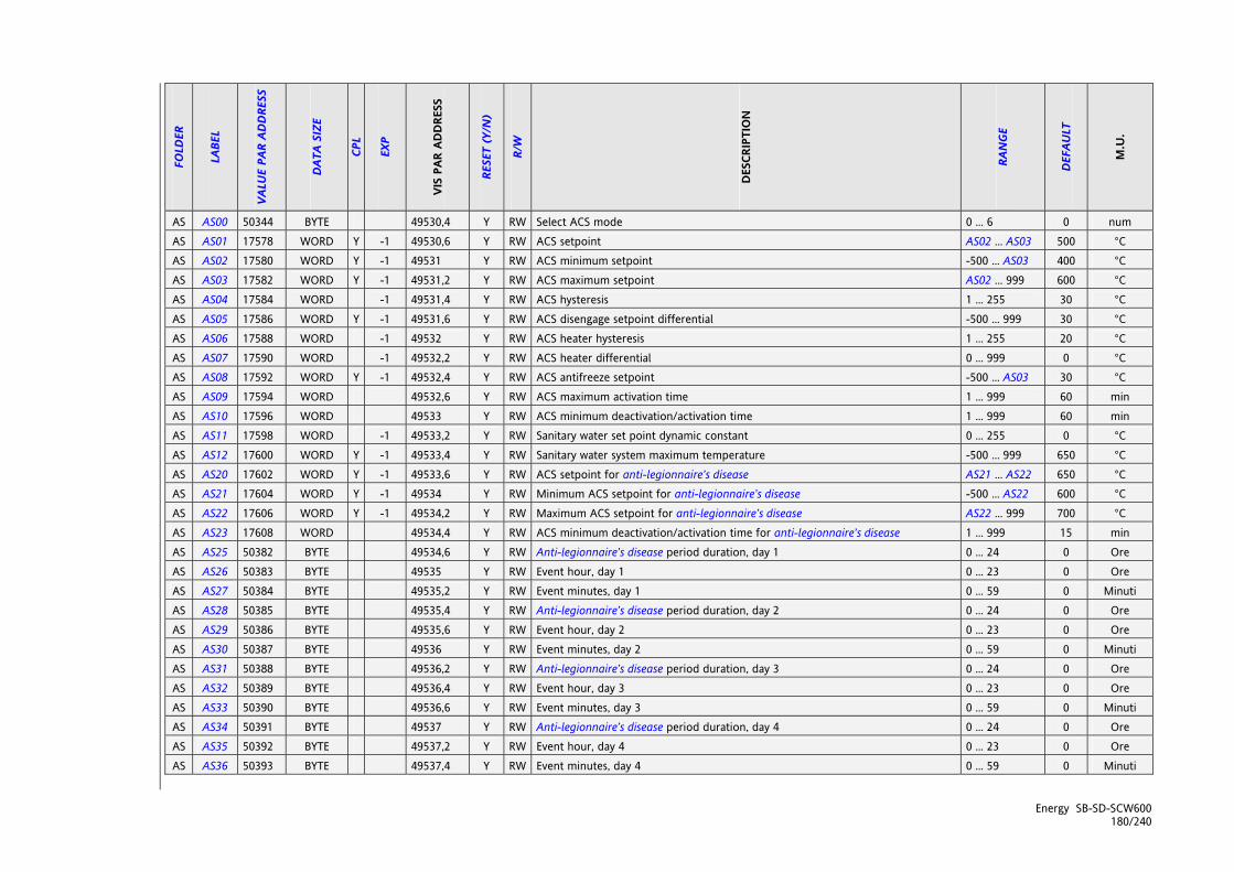
Energy SB-SD-SCW600 180/240
FOLD
ER
LABE
L
VALU
E PA
R AD
DRE
SS
DAT
A SI
ZE
CPL
EXP
VIS
PAR
ADD
RESS
RESE
T (Y
/N)
R/W
DES
CRIP
TIO
N
RAN
GE
DEF
AULT
M.U
.
AS AS00 50344 BYTE 49530,4 Y RW Select ACS mode 0 ... 6 0 num AS AS01 17578 WORD Y -1 49530,6 Y RW ACS setpoint AS02 ... AS03 500 °C AS AS02 17580 WORD Y -1 49531 Y RW ACS minimum setpoint -500 ... AS03 400 °C AS AS03 17582 WORD Y -1 49531,2 Y RW ACS maximum setpoint AS02 ... 999 600 °C AS AS04 17584 WORD -1 49531,4 Y RW ACS hysteresis 1 ... 255 30 °C AS AS05 17586 WORD Y -1 49531,6 Y RW ACS disengage setpoint differential -500 ... 999 30 °C AS AS06 17588 WORD -1 49532 Y RW ACS heater hysteresis 1 ... 255 20 °C AS AS07 17590 WORD -1 49532,2 Y RW ACS heater differential 0 ... 999 0 °C AS AS08 17592 WORD Y -1 49532,4 Y RW ACS antifreeze setpoint -500 ... AS03 30 °C AS AS09 17594 WORD 49532,6 Y RW ACS maximum activation time 1 ... 999 60 min AS AS10 17596 WORD 49533 Y RW ACS minimum deactivation/activation time 1 ... 999 60 min AS AS11 17598 WORD -1 49533,2 Y RW Sanitary water set point dynamic constant 0 ... 255 0 °C AS AS12 17600 WORD Y -1 49533,4 Y RW Sanitary water system maximum temperature -500 ... 999 650 °C AS AS20 17602 WORD Y -1 49533,6 Y RW ACS setpoint for anti-legionnaire’s disease AS21 ... AS22 650 °C AS AS21 17604 WORD Y -1 49534 Y RW Minimum ACS setpoint for anti-legionnaire’s disease -500 ... AS22 600 °C AS AS22 17606 WORD Y -1 49534,2 Y RW Maximum ACS setpoint for anti-legionnaire’s disease AS22 ... 999 700 °C AS AS23 17608 WORD 49534,4 Y RW ACS minimum deactivation/activation time for anti-legionnaire’s disease 1 ... 999 15 min AS AS25 50382 BYTE 49534,6 Y RW Anti-legionnaire’s disease period duration, day 1 0 ... 24 0 Ore AS AS26 50383 BYTE 49535 Y RW Event hour, day 1 0 ... 23 0 Ore AS AS27 50384 BYTE 49535,2 Y RW Event minutes, day 1 0 ... 59 0 Minuti AS AS28 50385 BYTE 49535,4 Y RW Anti-legionnaire’s disease period duration, day 2 0 ... 24 0 Ore AS AS29 50386 BYTE 49535,6 Y RW Event hour, day 2 0 ... 23 0 Ore AS AS30 50387 BYTE 49536 Y RW Event minutes, day 2 0 ... 59 0 Minuti AS AS31 50388 BYTE 49536,2 Y RW Anti-legionnaire’s disease period duration, day 3 0 ... 24 0 Ore AS AS32 50389 BYTE 49536,4 Y RW Event hour, day 3 0 ... 23 0 Ore AS AS33 50390 BYTE 49536,6 Y RW Event minutes, day 3 0 ... 59 0 Minuti AS AS34 50391 BYTE 49537 Y RW Anti-legionnaire’s disease period duration, day 4 0 ... 24 0 Ore AS AS35 50392 BYTE 49537,2 Y RW Event hour, day 4 0 ... 23 0 Ore AS AS36 50393 BYTE 49537,4 Y RW Event minutes, day 4 0 ... 59 0 Minuti
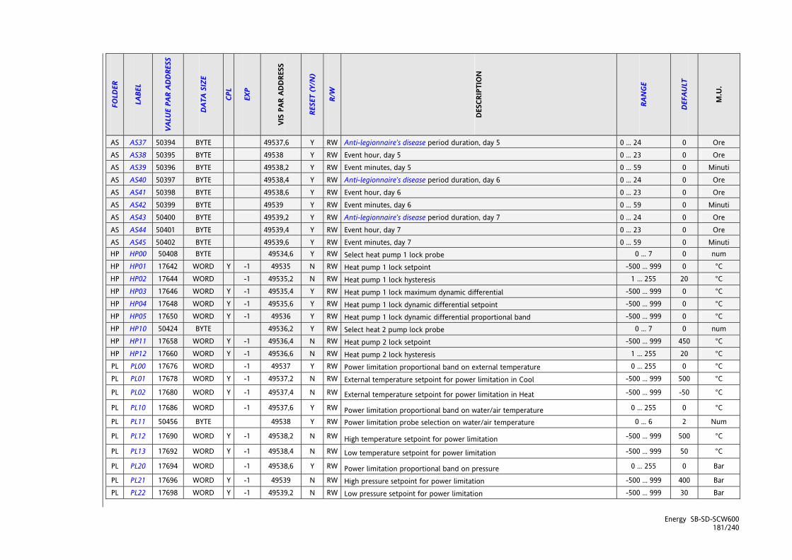
Energy SB-SD-SCW600 181/240
FOLD
ER
LABE
L
VALU
E PA
R AD
DRE
SS
DAT
A SI
ZE
CPL
EXP
VIS
PAR
ADD
RESS
RESE
T (Y
/N)
R/W
DES
CRIP
TIO
N
RAN
GE
DEF
AULT
M.U
.
AS AS37 50394 BYTE 49537,6 Y RW Anti-legionnaire’s disease period duration, day 5 0 ... 24 0 Ore AS AS38 50395 BYTE 49538 Y RW Event hour, day 5 0 ... 23 0 Ore AS AS39 50396 BYTE 49538,2 Y RW Event minutes, day 5 0 ... 59 0 Minuti AS AS40 50397 BYTE 49538,4 Y RW Anti-legionnaire’s disease period duration, day 6 0 ... 24 0 Ore AS AS41 50398 BYTE 49538,6 Y RW Event hour, day 6 0 ... 23 0 Ore AS AS42 50399 BYTE 49539 Y RW Event minutes, day 6 0 ... 59 0 Minuti AS AS43 50400 BYTE 49539,2 Y RW Anti-legionnaire’s disease period duration, day 7 0 ... 24 0 Ore AS AS44 50401 BYTE 49539,4 Y RW Event hour, day 7 0 ... 23 0 Ore AS AS45 50402 BYTE 49539,6 Y RW Event minutes, day 7 0 ... 59 0 Minuti HP HP00 50408 BYTE 49534,6 Y RW Select heat pump 1 lock probe 0 ... 7 0 num HP HP01 17642 WORD Y -1 49535 N RW Heat pump 1 lock setpoint -500 ... 999 0 °C HP HP02 17644 WORD -1 49535,2 N RW Heat pump 1 lock hysteresis 1 ... 255 20 °C HP HP03 17646 WORD Y -1 49535,4 Y RW Heat pump 1 lock maximum dynamic differential -500 ... 999 0 °C HP HP04 17648 WORD Y -1 49535,6 Y RW Heat pump 1 lock dynamic differential setpoint -500 ... 999 0 °C HP HP05 17650 WORD Y -1 49536 Y RW Heat pump 1 lock dynamic differential proportional band -500 ... 999 0 °C HP HP10 50424 BYTE 49536,2 Y RW Select heat 2 pump lock probe 0 ... 7 0 num HP HP11 17658 WORD Y -1 49536,4 N RW Heat pump 2 lock setpoint -500 ... 999 450 °C HP HP12 17660 WORD Y -1 49536,6 N RW Heat pump 2 lock hysteresis 1 ... 255 20 °C PL PL00 17676 WORD -1 49537 Y RW Power limitation proportional band on external temperature 0 ... 255 0 °C PL PL01 17678 WORD Y -1 49537,2 N RW External temperature setpoint for power limitation in Cool -500 ... 999 500 °C
PL PL02 17680 WORD Y -1 49537,4 N RW External temperature setpoint for power limitation in Heat -500 ... 999 -50 °C
PL PL10 17686 WORD -1 49537,6 Y RW Power limitation proportional band on water/air temperature 0 ... 255 0 °C
PL PL11 50456 BYTE 49538 Y RW Power limitation probe selection on water/air temperature 0 ... 6 2 Num
PL PL12 17690 WORD Y -1 49538,2 N RW High temperature setpoint for power limitation -500 ... 999 500 °C
PL PL13 17692 WORD Y -1 49538,4 N RW Low temperature setpoint for power limitation -500 ... 999 50 °C
PL PL20 17694 WORD -1 49538,6 Y RW Power limitation proportional band on pressure 0 ... 255 0 Bar
PL PL21 17696 WORD Y -1 49539 N RW High pressure setpoint for power limitation -500 ... 999 400 Bar PL PL22 17698 WORD Y -1 49539,2 N RW Low pressure setpoint for power limitation -500 ... 999 30 Bar
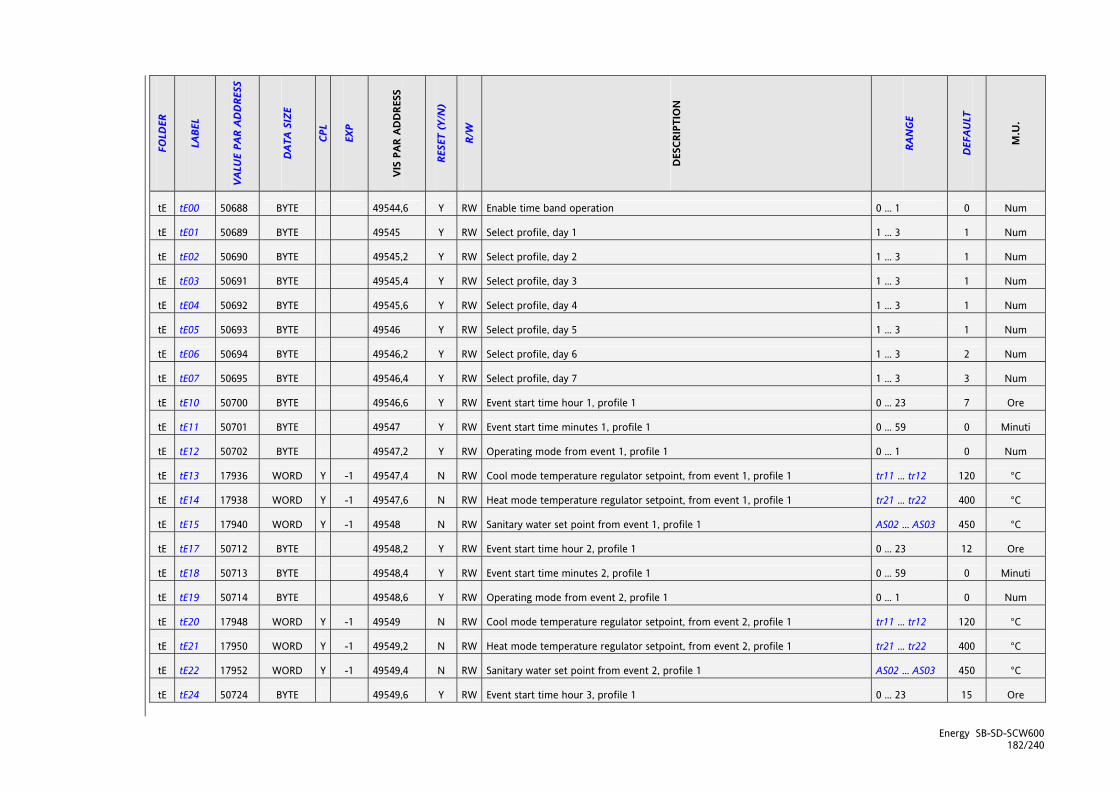
Energy SB-SD-SCW600 182/240
FOLD
ER
LABE
L
VALU
E PA
R AD
DRE
SS
DAT
A SI
ZE
CPL
EXP
VIS
PAR
ADD
RESS
RESE
T (Y
/N)
R/W
DES
CRIP
TIO
N
RAN
GE
DEF
AULT
M.U
.
tE tE00 50688 BYTE 49544,6 Y RW Enable time band operation 0 ... 1 0 Num
tE tE01 50689 BYTE 49545 Y RW Select profile, day 1 1 ... 3 1 Num
tE tE02 50690 BYTE 49545,2 Y RW Select profile, day 2 1 ... 3 1 Num
tE tE03 50691 BYTE 49545,4 Y RW Select profile, day 3 1 ... 3 1 Num
tE tE04 50692 BYTE 49545,6 Y RW Select profile, day 4 1 ... 3 1 Num
tE tE05 50693 BYTE 49546 Y RW Select profile, day 5 1 ... 3 1 Num
tE tE06 50694 BYTE 49546,2 Y RW Select profile, day 6 1 ... 3 2 Num
tE tE07 50695 BYTE 49546,4 Y RW Select profile, day 7 1 ... 3 3 Num
tE tE10 50700 BYTE 49546,6 Y RW Event start time hour 1, profile 1 0 ... 23 7 Ore
tE tE11 50701 BYTE 49547 Y RW Event start time minutes 1, profile 1 0 ... 59 0 Minuti
tE tE12 50702 BYTE 49547,2 Y RW Operating mode from event 1, profile 1 0 ... 1 0 Num
tE tE13 17936 WORD Y -1 49547,4 N RW Cool mode temperature regulator setpoint, from event 1, profile 1 tr11 ... tr12 120 °C
tE tE14 17938 WORD Y -1 49547,6 N RW Heat mode temperature regulator setpoint, from event 1, profile 1 tr21 ... tr22 400 °C
tE tE15 17940 WORD Y -1 49548 N RW Sanitary water set point from event 1, profile 1 AS02 ... AS03 450 °C
tE tE17 50712 BYTE 49548,2 Y RW Event start time hour 2, profile 1 0 ... 23 12 Ore
tE tE18 50713 BYTE 49548,4 Y RW Event start time minutes 2, profile 1 0 ... 59 0 Minuti
tE tE19 50714 BYTE 49548,6 Y RW Operating mode from event 2, profile 1 0 ... 1 0 Num
tE tE20 17948 WORD Y -1 49549 N RW Cool mode temperature regulator setpoint, from event 2, profile 1 tr11 ... tr12 120 °C
tE tE21 17950 WORD Y -1 49549,2 N RW Heat mode temperature regulator setpoint, from event 2, profile 1 tr21 ... tr22 400 °C
tE tE22 17952 WORD Y -1 49549,4 N RW Sanitary water set point from event 2, profile 1 AS02 ... AS03 450 °C
tE tE24 50724 BYTE 49549,6 Y RW Event start time hour 3, profile 1 0 ... 23 15 Ore
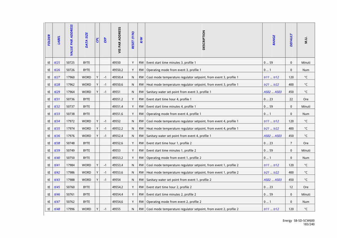
Energy SB-SD-SCW600 183/240
FOLD
ER
LABE
L
VALU
E PA
R AD
DRE
SS
DAT
A SI
ZE
CPL
EXP
VIS
PAR
ADD
RESS
RESE
T (Y
/N)
R/W
DES
CRIP
TIO
N
RAN
GE
DEF
AULT
M.U
.
tE tE25 50725 BYTE 49550 Y RW Event start time minutes 3, profile 1 0 ... 59 0 Minuti
tE tE26 50726 BYTE 49550,2 Y RW Operating mode from event 3, profile 1 0 ... 1 0 Num
tE tE27 17960 WORD Y -1 49550,4 N RW Cool mode temperature regulator setpoint, from event 3, profile 1 tr11 ... tr12 120 °C
tE tE28 17962 WORD Y -1 49550,6 N RW Heat mode temperature regulator setpoint, from event 3, profile 1 tr21 ... tr22 400 °C
tE tE29 17964 WORD Y -1 49551 N RW Sanitary water set point from event 3, profile 1 AS02 ... AS03 450 °C
tE tE31 50736 BYTE 49551,2 Y RW Event start time hour 4, profile 1 0 ... 23 22 Ore
tE tE32 50737 BYTE 49551,4 Y RW Event start time minutes 4, profile 1 0 ... 59 0 Minuti
tE tE33 50738 BYTE 49551,6 Y RW Operating mode from event 4, profile 1 0 ... 1 0 Num
tE tE34 17972 WORD Y -1 49552 N RW Cool mode temperature regulator setpoint, from event 4, profile 1 tr11 ... tr12 120 °C
tE tE35 17974 WORD Y -1 49552,2 N RW Heat mode temperature regulator setpoint, from event 4, profile 1 tr21 ... tr22 400 °C
tE tE36 17976 WORD Y -1 49552,4 N RW Sanitary water set point from event 4, profile 1 AS02 ... AS03 450 °C
tE tE38 50748 BYTE 49552,6 Y RW Event start time hour 1, profile 2 0 ... 23 7 Ore
tE tE39 50749 BYTE 49553 Y RW Event start time minutes 1, profile 2 0 ... 59 0 Minuti
tE tE40 50750 BYTE 49553,2 Y RW Operating mode from event 1, profile 2 0 ... 1 0 Num
tE tE41 17984 WORD Y -1 49553,4 N RW Cool mode temperature regulator setpoint, from event 1, profile 2 tr11 ... tr12 120 °C
tE tE42 17986 WORD Y -1 49553,6 N RW Heat mode temperature regulator setpoint, from event 1, profile 2 tr21 ... tr22 400 °C
tE tE43 17988 WORD Y -1 49554 N RW Sanitary water set point from event 1, profile 2 AS02 ... AS03 450 °C
tE tE45 50760 BYTE 49554,2 Y RW Event start time hour 2, profile 2 0 ... 23 12 Ore
tE tE46 50761 BYTE 49554,4 Y RW Event start time minutes 2, profile 2 0 ... 59 0 Minuti
tE tE47 50762 BYTE 49554,6 Y RW Operating mode from event 2, profile 2 0 ... 1 0 Num
tE tE48 17996 WORD Y -1 49555 N RW Cool mode temperature regulator setpoint, from event 2, profile 2 tr11 ... tr12 120 °C

Energy SB-SD-SCW600 184/240
FOLD
ER
LABE
L
VALU
E PA
R AD
DRE
SS
DAT
A SI
ZE
CPL
EXP
VIS
PAR
ADD
RESS
RESE
T (Y
/N)
R/W
DES
CRIP
TIO
N
RAN
GE
DEF
AULT
M.U
.
tE tE49 17998 WORD Y -1 49555,2 N RW Heat mode temperature regulator setpoint, from event 2, profile 2 tr21 ... tr22 400 °C
tE tE50 18000 WORD Y -1 49555,4 N RW Sanitary water set point from event 2, profile 2 AS02 ... AS03 450 °C
tE tE52 50772 BYTE 49555,6 Y RW Event start time hour 3, profile 2 0 ... 23 15 Ore
tE tE53 50773 BYTE 49556 Y RW Event start time minutes 3, profile 2 0 ... 59 0 Minuti
tE tE54 50774 BYTE 49556,2 Y RW Operating mode from event 3, profile 2 0 ... 1 0 Num
tE tE55 18008 WORD Y -1 49556,4 N RW Cool mode temperature regulator setpoint, from event 3, profile 2 tr11 ... tr12 120 °C
tE tE56 18010 WORD Y -1 49556,6 N RW Heat mode temperature regulator setpoint, from event 3, profile 2 tr21 ... tr22 400 °C
tE tE57 18012 WORD Y -1 49557 N RW Sanitary water set point from event 3, profile 2 AS02 ... AS03 450 °C
tE tE59 50784 BYTE 49557,2 Y RW Event start time hour 4, profile 2 0 ... 23 22 Ore
tE tE60 50785 BYTE 49557,4 Y RW Event start time minutes 4, profile 2 0 ... 59 0 Minuti
tE tE61 50786 BYTE 49557,6 Y RW Operating mode from event 4, profile 2 0 ... 1 0 Num
tE tE62 18020 WORD Y -1 49558 N RW Cool mode temperature regulator setpoint, from event 4, profile 2 tr11 ... tr12 120 °C
tE tE63 18022 WORD Y -1 49558,2 N RW Heat mode temperature regulator setpoint, from event 4, profile 2 tr21 ... tr22 400 °C
tE tE64 18024 WORD Y -1 49558,4 N RW Sanitary water set point from event 4, profile 2 AS02 ... AS03 450 °C
tE tE66 50796 BYTE 49558,6 Y RW Event start time hour 1, profile 3 0 ... 23 7 Ore
tE tE67 50797 BYTE 49559 Y RW Event start time minutes 1, profile 3 0 ... 59 0 Minuti
tE tE68 50798 BYTE 49559,2 Y RW Operating mode from event 1, profile 3 0 ... 1 0 Num
tE tE69 18032 WORD Y -1 49559,4 N RW Cool mode temperature regulator setpoint, from event 1, profile 3 tr11 ... tr12 120 °C
tE tE70 18034 WORD Y -1 49559,6 N RW Heat mode temperature regulator setpoint, from event 1, profile 3 tr21 ... tr22 400 °C
tE tE71 18036 WORD Y -1 49560 N RW Sanitary water set point from event 1, profile 3 AS02 ... AS03 450 °C
tE tE73 50808 BYTE 49560,2 Y RW Event start time hour 2, profile 3 0 ... 23 12 Ore
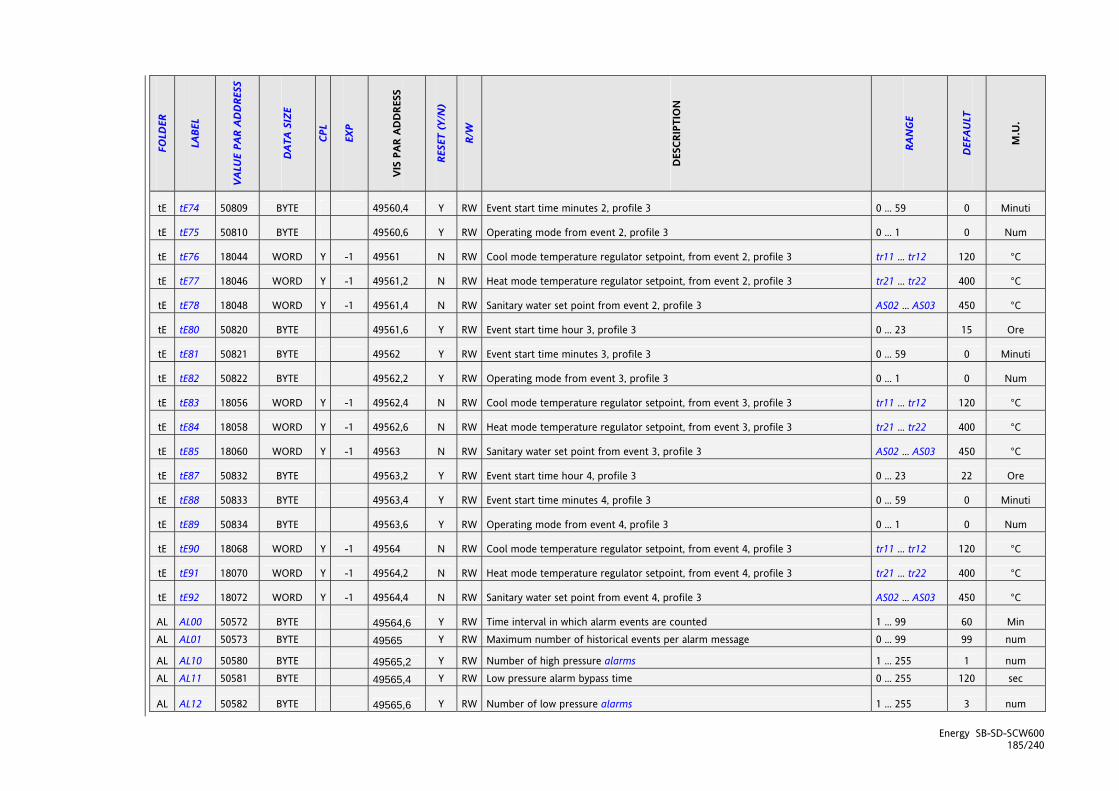
Energy SB-SD-SCW600 185/240
FOLD
ER
LABE
L
VALU
E PA
R AD
DRE
SS
DAT
A SI
ZE
CPL
EXP
VIS
PAR
ADD
RESS
RESE
T (Y
/N)
R/W
DES
CRIP
TIO
N
RAN
GE
DEF
AULT
M.U
.
tE tE74 50809 BYTE 49560,4 Y RW Event start time minutes 2, profile 3 0 ... 59 0 Minuti
tE tE75 50810 BYTE 49560,6 Y RW Operating mode from event 2, profile 3 0 ... 1 0 Num
tE tE76 18044 WORD Y -1 49561 N RW Cool mode temperature regulator setpoint, from event 2, profile 3 tr11 ... tr12 120 °C
tE tE77 18046 WORD Y -1 49561,2 N RW Heat mode temperature regulator setpoint, from event 2, profile 3 tr21 ... tr22 400 °C
tE tE78 18048 WORD Y -1 49561,4 N RW Sanitary water set point from event 2, profile 3 AS02 ... AS03 450 °C
tE tE80 50820 BYTE 49561,6 Y RW Event start time hour 3, profile 3 0 ... 23 15 Ore
tE tE81 50821 BYTE 49562 Y RW Event start time minutes 3, profile 3 0 ... 59 0 Minuti
tE tE82 50822 BYTE 49562,2 Y RW Operating mode from event 3, profile 3 0 ... 1 0 Num
tE tE83 18056 WORD Y -1 49562,4 N RW Cool mode temperature regulator setpoint, from event 3, profile 3 tr11 ... tr12 120 °C
tE tE84 18058 WORD Y -1 49562,6 N RW Heat mode temperature regulator setpoint, from event 3, profile 3 tr21 ... tr22 400 °C
tE tE85 18060 WORD Y -1 49563 N RW Sanitary water set point from event 3, profile 3 AS02 ... AS03 450 °C
tE tE87 50832 BYTE 49563,2 Y RW Event start time hour 4, profile 3 0 ... 23 22 Ore
tE tE88 50833 BYTE 49563,4 Y RW Event start time minutes 4, profile 3 0 ... 59 0 Minuti
tE tE89 50834 BYTE 49563,6 Y RW Operating mode from event 4, profile 3 0 ... 1 0 Num
tE tE90 18068 WORD Y -1 49564 N RW Cool mode temperature regulator setpoint, from event 4, profile 3 tr11 ... tr12 120 °C
tE tE91 18070 WORD Y -1 49564,2 N RW Heat mode temperature regulator setpoint, from event 4, profile 3 tr21 ... tr22 400 °C
tE tE92 18072 WORD Y -1 49564,4 N RW Sanitary water set point from event 4, profile 3 AS02 ... AS03 450 °C
AL AL00 50572 BYTE 49564,6 Y RW Time interval in which alarm events are counted 1 ... 99 60 Min AL AL01 50573 BYTE 49565 Y RW Maximum number of historical events per alarm message 0 ... 99 99 num
AL AL10 50580 BYTE 49565,2 Y RW Number of high pressure alarms 1 ... 255 1 num AL AL11 50581 BYTE 49565,4 Y RW Low pressure alarm bypass time 0 ... 255 120 sec
AL AL12 50582 BYTE 49565,6 Y RW Number of low pressure alarms 1 ... 255 3 num

Energy SB-SD-SCW600 186/240
FOLD
ER
LABE
L
VALU
E PA
R AD
DRE
SS
DAT
A SI
ZE
CPL
EXP
VIS
PAR
ADD
RESS
RESE
T (Y
/N)
R/W
DES
CRIP
TIO
N
RAN
GE
DEF
AULT
M.U
.
AL AL13 50583 BYTE 49566 Y RW Enable low pressure alarm during defrost 0 ... 1 0 num
AL AL14 50584 BYTE 49566,2 Y RW Flow switch bypass time after primary circuit water pump enabled 0 ... 255 15 sec AL AL15 50585 BYTE 49566,4 Y RW Flow switch activation/deactivation time on internal circuit automatic alarm 0 ... 255 2 sec AL AL16 50586 BYTE 49566,6 Y RW Enable flow switch time for primary circuit manual alarm 0 ... 255 2 Sec x 10 AL AL17 50587 BYTE 49567 Y RW Flow switch bypass time after open-circuit pump activated 0 ... 255 15 sec AL AL18 50588 BYTE 49567,2 Y RW Flow switch activation/deactivation time on external circuit automatic alarm 0 ... 255 2 sec
AL AL19 50589 BYTE 49567,4 Y RW Time flow switch on before open-circuit manual alarm 0 ... 255 2 sec x 10
AL AL20 50590 BYTE 49567,6 Y RW Bypass compressor thermal switch alarm time 0 ... 255 1 sec
AL AL21 50591 BYTE 49568 Y RW Number of compressor thermal switch alarms 1 ... 255 1 num
AL AL22 50592 BYTE 49568,2 Y RW Compressor oil pressure switch alarm bypass time 0 ... 255 1 sec
AL AL23 50593 BYTE 49568,4 Y RW Number of compressor oil pressure switch alarms 1 ... 255 1 num
AL AL24 50594 BYTE 49568,6 Y RW Number of primary intercooler fan thermal switch alarms 1 ... 255 1 num
AL AL25 50595 BYTE 49569 Y RW Number of open-system intercooler fan thermal switch alarms 1 ... 255 1 num
AL AL26 50596 BYTE 49569,2 Y RW Number of primary circuit pump thermal switch alarms 1 ... 255 2 num
AL AL27 50597 BYTE 49569,4 Y RW Number of open-system pump thermal switch alarms 1 ... 255 2 num
AL AL40 17840 WORD Y -1 49569,6 N RW High pressure alarm regulator setpoint from analogue input -500 ... 999 420 Bar
AL AL41 17842 WORD -1 49570 N RW High pressure alarm regulator hysteresis from analogue input 1 ... 255 20 Bar
AL AL42 50612 BYTE 49570,2 Y RW Number of high pressure alarms from analogue input 1 ... 255 1 num
AL AL43 50613 BYTE 49570,4 Y RW Low pressure alarm bypass time from analogue input 0 ... 255 10 sec
AL AL44 17846 WORD Y -1 49570,6 N Low pressure alarm regulator setpoint from analogue input -500 ... 999 20 Bar
AL AL45 17848 WORD -1 49571 N RW Low pressure alarm regulator hysteresis from analogue input 1 ... 255 20 Bar

Energy SB-SD-SCW600 187/240
FOLD
ER
LABE
L
VALU
E PA
R AD
DRE
SS
DAT
A SI
ZE
CPL
EXP
VIS
PAR
ADD
RESS
RESE
T (Y
/N)
R/W
DES
CRIP
TIO
N
RAN
GE
DEF
AULT
M.U
.
AL AL46 50618 BYTE 49571,2 Y RW Number of low pressure alarms from analogue input 1 ... 255 2 num
AL AL47 17852 WORD Y -1 49571,4 N RW High temperature alarm regulator setpoint from analogue input -500 ... 999 800 °C
AL AL48 17854 WORD -1 49571,6 N RW High temperature alarm regulator hysteresis from analogue input 1 ... 255 20 °C
AL AL49 50624 BYTE 49572 Y RW High temperature time per alarm 0 ... 255 30 sec x 10
AL AL50 50625 BYTE 49572,2 Y RW Primary circuit anti-freeze alarm bypass time 0 ... 255 1 min
AL AL51 17858 WORD Y -1 49572,4 N RW Primary circuit anti-freeze regulator setpoint alarm -500 ... 999 40 °C
AL AL52 17860 WORD -1 49572,6 N RW Primary circuit anti-freeze regulator hysteresis alarm 1 ... 255 20 °C
AL AL53 50630 BYTE 49573 Y RW Number of primary circuit anti-freeze alarms 1 ... 255 1 num
AL AL54 50631 BYTE 49573,2 Y RW Open-system circuit anti-freeze alarm bypass time 0 ... 255 1 min
AL AL55 17864 WORD Y -1 49573,4 N RW Open-system circuit anti-freeze regulator setpoint alarm -500 ... 999 40 °C
AL AL56 17866 WORD -1 49573,6 N RW Open-system circuit anti-freeze regulator hysteresis alarm 1 ... 255 20 °C
AL AL57 50636 BYTE 49574 Y RW Number of open-system anti-freeze alarms 1 ... 255 1 num
AL AL70 50640 BYTE 49574,2 Y RW Enable gas low in plant alarm 0 ... 1 0 num
AL AL71 50641 BYTE 49574,4 Y RW Gas low in plant alarm bypass time 0 ... 255 5 min
AL AL72 17874 WORD -1 49574,6 N RW Gas low in plant alarm differential 0 ... 255 20 °C
AL AL73 50644 BYTE 49575 Y RW Time gas low in plant before alarm 0 ... 255 30 min
AL AL80 50652 BYTE 49575,2 Y RW Compressor start time on maintenance signal 0 ... 255 0 orex100
AL AL81 50653 BYTE 49575,4 Y RW Internal pump start time on maintenance signal 0 ... 255 0 orex100
AL AL82 50654 BYTE 49575,6 Y RW Internal pump start time on maintenance signal 0 ... 255 0 orex100

Energy SB-SD-SCW600 188/240
25.2.2 Folder visibility table
LABEL ADDRESS R/W DESCRIPTION DATA SIZE RANGE DEFAULT U.M.
_VisSt0 49424 RW Folder Ai visibility 2 bit 0 ... 3 3 num
_VisSt1 49424,2 RW Folder di visibility 2 bit 0 ... 3 3 num
_VisSt2 49424,4 RW Folder AO visibility 2 bit 0 ... 3 3 num
_VisSt3 49424,6 RW Folder dO visibility 2 bit 0 ... 3 3 num
_VisSt4 49425 RW Folder SP visibility 2 bit 0 ... 3 3 num
_VisSt5 49425,2 RW Folder Sr visibility 2 bit 0 ... 3 3 num
_VisSt6 49425,4 RW Folder Hr visibility 2 bit 0 ... 3 3 num
_VisPa0 49425,6 RW Folder Par visibility 2 bit 0 ... 3 3 num
_VisPa1 49426 RW Folder FnC visibility 2 bit 0 ... 3 3 num
_VisPa2 49426,2 RW Folder PASS visibility 2 bit 0 ... 3 3 num
_VisPa3 49426,4 RW Folder EU visibility 2 bit 0 ... 3 3 num
_VisSSp0 49426,6 RW Folder SP\COOL visibility 2 bit 0 ... 3 3 num
_VisSSp1 49427 RW Folder SP\HEAT visibility 2 bit 0 ... 3 3 num
_VisSSr0 49427,2 RW Folder Sr\COOL visibility 2 bit 0 ... 3 3 num
_VisSSr1 49427,4 RW Folder Sr\HEAT visibility 2 bit 0 ... 3 3 num
_VisPP0 49427,6 RW Folder Par\CL visibility 2 bit 0 ... 3 3 num
_VisPP1 49428 RW Folder Par\Cr visibility 2 bit 0 ... 3 3 num
_VisPP3 49428,4 RW Folder Par\CF visibility 2 bit 0 ... 3 3 num
_VisPP4 49428,6 RW Folder Par\Ui visibility 2 bit 0 ... 3 3 num
_VisPP5 49429 RW Folder Par\tr visibility 2 bit 0 ... 3 3 num
_VisPP6 49429,2 RW Folder Par\St visibility 2 bit 0 ... 3 3 num
_VisPP7 49429,4 RW Folder Par\CP visibility 2 bit 0 ... 3 3 num
_VisPP8 49429,6 RW Folder Par\Pi visibility 2 bit 0 ... 3 3 num
_VisPP9 49430 RW Folder Par\Fi visibility 2 bit 0 ... 3 3 num
_VisPP10 49430,2 RW Folder Par\FE visibility 2 bit 0 ... 3 3 num
_VisPP11 49430,4 RW Folder Par\PE visibility 2 bit 0 ... 3 3 num
_VisPP12 49430,6 RW Folder Par\Hi visibility 2 bit 0 ... 3 3 num
_VisPP13 49431 RW Folder Par\HE visibility 2 bit 0 ... 3 3 num
_VisPP14 49431,2 RW Folder Par\HA visibility 2 bit 0 ... 3 3 num

Energy SB-SD-SCW600 189/240
LABEL ADDRESS R/W DESCRIPTION DATA SIZE RANGE DEFAULT U.M.
_VisPP15 49431,4 RW Folder Par\br visibility 2 bit 0 ... 3 3 num
_VisPP17 49432 RW Folder Par\dF visibility 2 bit 0 ... 3 3 num
_VisPP18 49432,2 RW Folder Par\dS visibility 2 bit 0 ... 3 3 num
_VisPP19 49432,4 RW Folder Par\Ad visibility 2 bit 0 ... 3 3 num
_VisPP20 49432,6 RW Folder Par\AF visibility 2 bit 0 ... 3 3 num
_VisPP21 49433 RW Folder Par\AS visibility 2 bit 0 ... 3 3 num
_VisPP22 49433,2 RW Folder Par\HP visibility 2 bit 0 ... 3 3 num
_VisPP23 49433,4 RW Folder Par\PL visibility 2 bit 0 ... 3 3 num
_VisPP24 49433,6 RW Folder Par\tE visibility 2 bit 0 ... 3 3 num
_VisPP25 49434 RW Folder Par\AL visibility 2 bit 0 ... 3 3 num
_VisPF0 49434,4 RW Folder FnC\dEF visibility 2 bit 0 ... 3 3 num
_VisPF1 49434,6 RW Folder FnC\tA visibility 2 bit 0 ... 3 3 num
_VisPF2 49435 RW Folder FnC\St visibility 2 bit 0 ... 3 3 num
_VisPF3 49435,2 RW Folder FnC\CC visibility 2 bit 0 ... 3 3 num
_VisPF4 49435,4 RW Folder FnC\Eur visibility 2 bit 0 ... 3 3 num
_VisPFCC0 49576 RW Folder FnC\CC\UL visibility 2 bit 0 ... 3 3 num
_VisPFCC1 49576,2 RW Folder FnC\CC\dL visibility 2 bit 0 ... 3 3 num
_VisPFCC2 49576,4 RW Folder FnC\CC\Fr visibility 2 bit 0 ... 3 3 num

Energy SB-SD-SCW600 190/240
25.2.3 Client Table
RESOURCE LABEL ADDRESS DATA SIZE CPL EXP R/W DESCRIPTION RANGE DEFAULT M.U.
AI LocalAInput[0] 412 WORD Y -1 R Analogue input AIL1 -500 ... 999 0 °C
AI LocalAInput[1] 414 WORD Y -1 R Analogue input AIL2 -500 ... 999 0 °C
AI LocalAInput[2] 416 WORD Y -1 R Analogue input AIL3 -500 ... 999 0 °C/Bar
AI LocalAInput[3] 418 WORD Y -1 R Analogue input AIL4 -500 ... 999 0 °C/Bar
AI LocalAInput[4] 420 WORD Y -1 R Analogue input AIL5 -500 ... 999 0 °C
DI LocalDigInput DIL1 33158 1 bit R Digital input DIL1 0 ... 1 0 num
DI LocalDigInput DIL2 33158,1 1 bit R Digital input DIL2 0 ... 1 0 num
DI LocalDigInput DIL3 33158,2 1 bit R Digital input DIL3 0 ... 1 0 num
DI LocalDigInput DIL4 33158,3 1 bit R Digital input DIL4 0 ... 1 0 num
DI LocalDigInput DIL5 33158,4 1 bit R Digital input DIL5 0 ... 1 0 num
DI LocalDigInput DIL6 33158,5 1 bit R Digital input DIL6 0 ... 1 0 num
DI LocalDigInput DIL7 33158,6 1 bit R Digital input DIL7 0 ... 1 0 num
DO LocalDigOutput DOL1 33159,2 1 bit R Digital output DOL1 0 ... 1 0 num
DO LocalDigOutput DOL2 33159,3 1 bit R Digital output DOL2 0 ... 1 0 num
DO LocalDigOutput DOL3 33159,4 1 bit R Digital output DOL3 0 ... 1 0 num
DO LocalDigOutput DOL4 33159 1 bit R Digital output DOL4 0 ... 1 0 num
DO LocalDigOutput DOL5 33159,1 1 bit R Digital output DOL5 0 ... 1 0 num
DO LocalDigOutput DOL6 33159,5 1 bit R Digital output DOL6 0 ... 1 0 num
AO LocalDigOutput AOL1 33159,6 1 bit R Digital output AOL1 0 ... 1 0 num
AO LocalDigOutput AOL2 33159,7 1 bit R Digital output AOL2 0 ... 1 0 num
AO Analog.Out TC1 33224 BYTE Y R Analogue output TCL1 0 ... 100 0 num
AO Analog.Out AOL1 33225 BYTE Y R Analogue output AOL1 0 ... 100 0 num
AO Analog.Out AOL2 33226 BYTE Y R Analogue output AOL2 0 ... 100 0 num
AO Analog.Out ALO3 466 WORD Y -1 R Analogue output AOL3 0 ... 999 0 num
AO Analog.Out AOL4 468 WORD Y -1 R Analogue output AOL4 0 ... 999 0 num
AO Analog.Out AOL5 470 WORD Y -1 R Analogue output AOL5 0 ... 999 0 num
AI RemAInput[0] 854 WORD Y -1 R Analogue input AIr1 -500 ... 999 0 °C

Energy SB-SD-SCW600 191/240
RESOURCE LABEL ADDRESS DATA SIZE CPL EXP R/W DESCRIPTION RANGE DEFAULT M.U.
AI RemAInput[1] 856 WORD Y -1 R Analogue input AIr2 -500 ... 999 0 °C/Bar
setpoint Setpoint Cool reale 975 WORD Y -1 R Cooling mode set point -500 ... 999 0 °C
setpoint Setpoint Heat reale 977 WORD Y -1 R Heating mode set point -500 ... 999 0 °C
setpoint SBSetACSReale 1042 WORD Y -1 R ACS or anti-legionnaire’s disease setpoint -500 ... 999 0 °C
hysteresis Isteresi Cool reale 979 WORD Y -1 R Cooling mode hysteresis -500 ... 999 0 °C
hysteresis Isteresi Heat reale 981 WORD Y -1 R Heating mode hysteresis -500 ... 999 0 °C
time _TimMinOnOnCps 542 WORD R Compressors minimum on/on time timer 0 ... 32768 0 s
time _TimMinOfOfCps 544 WORD R Compressors minimum off/off time timer 0 ... 32768 0 s
time _TimMinOnOnPrz 546 WORD R Capacity steps minimum on/on time timer 0 ... 32768 0 s
time _TimMinOfOfPrz 548 WORD R Capacity steps minimum off/off time timer 0 ... 32768 0 s
time _TimMinOfOnCp0 550 WORD R Compressor 1 minimum off/on time timer 0 ... 32768 0 s
time _TimMinOfOnCp1 552 WORD R Compressor 2 minimum off/on time timer 0 ... 32768 0 s
time _TimMinOfOnCp2 554 WORD R Compressor 3 minimum off/on time timer 0 ... 32768 0 s
time _TimMinOfOnCp3 556 WORD R Compressor 4 minimum off/on time timer 0 ... 32768 0 s
time _TimMinOnOnCp0 558 WORD R Compressor 1 minimum on/on time timer 0 ... 32768 0 s
time _TimMinOnOnCp1 560 WORD R Compressor 2 minimum on/on time timer 0 ... 32768 0 s
time _TimMinOnOnCp2 562 WORD R Compressor 3 minimum on/on time timer 0 ... 32768 0 s
time _TimMinOnOnCp3 564 WORD R Compressor 4 minimum on/on time timer 0 ... 32768 0 s
time _TimMinOnCp0 566 WORD R Compressor 1 minimum on time timer 0 ... 32768 0 s
time _TimMinOnCp1 568 WORD R Compressor 2 minimum on time timer 0 ... 32768 0 s
time _TimMinOnCp2 570 WORD R Compressor 3 minimum on time timer 0 ... 32768 0 s
time _TimMinOnCp3 572 WORD R Compressor 4 minimum on time timer 0 ... 32768 0 s
time _TimEntraSbriC1 582 WORD R Circuit 1 defrost interval/duration time timer 0 ... 32768 0 s
time _TimEntraSbriC2 584 WORD R Circuit 2 defrost interval/duration time timer 0 ... 32768 0 s
time _TimSgoccioC1 586 WORD R Circuit 1 dripping time timer 0 ... 32768 0 s
time _TimSgoccioC2 588 WORD R Circuit 2 dripping time timer 0 ... 32768 0 s
time _TimRitOnCpPomPri 592 WORD R Switch-on delay timer for compressors after primary pump 0 ... 32768 0 s
time _TimRitOfPomPriCp 594 WORD R Switch-off delay timer for primary pump after compressors 0 ... 32768 0 s
time _TimASPMaxAtt 676 WORD R Timer maximum ACS on time 0 ... 32768 0 s
time _TimASPDisAtt 678 WORD R Timer minimum ACS off/on time 0 ... 32768 0 s

Energy SB-SD-SCW600 192/240
RESOURCE LABEL ADDRESS DATA SIZE CPL EXP R/W DESCRIPTION RANGE DEFAULT M.U.
time _TimALPDisAtt 680 WORD R Timer minimum ACS off/on time for anti-legionnaire’s disease 0 ... 32768 0 s
state _SbrinOnC1 33812,2 1 bit R Defrosting status 0 ... 1 0 num
state _SbrinOnC2 33812,3 1 bit R Defrosting status 0 ... 1 0 num
mode _MemoOff 33028 1 bit R Device in OFF 0 ... 1 0 num
mode _MemoRemotOff 33028,1 1 bit R Device in OFF 0 ... 1 0 num
mode _MemoLocalStBy 33028,2 1 bit R Device in STAND BY 0 ... 1 0 num
mode _MemoRemotStBy 33028,3 1 bit R Device in STAND BY 0 ... 1 0 num
mode _MemoLocalCool 33028,4 1 bit R Device in COOL 0 ... 1 0 num
mode _MemoRemotCool 33028,5 1 bit R Device in COOL 0 ... 1 0 num
mode _MemoLocalHeat 33028,6 1 bit R Device in HEAT 0 ... 1 0 num
mode _MemoRemotHeat 33028,7 1 bit R Device in HEAT 0 ... 1 0 num
counter STCPOreFunz[0] 939 WORD R Operation hours compressor 1 0 ... 65535 0 h
counter STCPOreFunz[1] 941 WORD R Operation hours compressor 2 0 ... 65535 0 h
counter STCPOreFunz[2] 943 WORD R Operation hours compressor 3 0 ... 65535 0 h
counter STCPOreFunz[3] 945 WORD R Operation hours compressor 4 0 ... 65535 0 h
counter STPMOreFunz[0] 947 WORD R Operation hours pump 1 0 ... 65535 0 h
counter STPMOreFunz[1] 949 WORD R Operation hours pump 2 0 ... 65535 0 h
counter STPMOreFunz[2] 951 WORD R Operation hours pump 3 0 ... 65535 0 h
differential SBDiffSetPoint 995 WORD Y -1 R Temperature control set point dynamic differential -500 ... 999 0 °C
offset SBDiffAdaptive 997 WORD Y -1 R Adaptive function offset -500 ... 999 0 °C
differential STDiffResPri 999 WORD Y -1 R Integrated electric heater set point dynamic differential -500 ... 999 0 °C
differential STDiffBoiler 1001 WORD Y -1 R Boiler set point dynamic differential -500 ... 999 0 °C
setpoint SBSetStartSbri 1009 WORD Y -1 R Defrost start set point -500 ... 999 0 °C
state SBCircuiti[0].OutAttive 33791 BYTE R Temperature control steps supplied circuit 1 0 ... 4 0 num
state SBCircuiti[0].OutAttive 33797 BYTE R Temperature control steps supplied circuit 2 0 ... 4 0 num
alarm Er00 33104 1 bit R General alarm 0 ... 1 0 flag
alarm Er01 33104,1 1 bit R Circuit 1 digital high pressure alarm 0 ... 1 0 flag
alarm Er02 33104,2 1 bit R Circuit 2 digital high pressure alarm 0 ... 1 0 flag
alarm Er03 33104,3 1 bit R Circuit 1 analogue high pressure alarm 0 ... 1 0 flag
alarm Er04 33104,4 1 bit R Circuit 2 analogue high pressure alarm 0 ... 1 0 flag

Energy SB-SD-SCW600 193/240
RESOURCE LABEL ADDRESS DATA SIZE CPL EXP R/W DESCRIPTION RANGE DEFAULT M.U.
alarm Er05 33104,5 1 bit R Circuit 1 digital low pressure alarm 0 ... 1 0 flag
alarm Er06 33104,6 1 bit R Circuit 2 digital low pressure alarm 0 ... 1 0 flag
alarm Er07 33104,7 1 bit R Circuit 1 analogue low pressure alarm 0 ... 1 0 flag
alarm Er08 33105 1 bit R Circuit 2 analogue low pressure alarm 0 ... 1 0 flag
alarm Er09 33105,1 1 bit R Machine low charge alarm 0 ... 1 0 flag
alarm Er10 33105,2 1 bit R Compressor 1 thermal switch alarm 0 ... 1 0 flag
alarm Er11 33105,3 1 bit R Compressor 2 thermal switch alarm 0 ... 1 0 flag
alarm Er12 33105,4 1 bit R Compressor 3 thermal switch alarm 0 ... 1 0 flag
alarm Er13 33105,5 1 bit R Compressor 4 thermal switch alarm 0 ... 1 0 flag
alarm Er15 33105,7 1 bit R Compressor 1 oil pressure switch alarm 0 ... 1 0 flag
alarm Er16 33106 1 bit R Compressor 2 oil pressure switch alarm 0 ... 1 0 flag
alarm Er17 33106,1 1 bit R Compressor 3 oil pressure switch alarm 0 ... 1 0 flag
alarm Er18 33106,2 1 bit R Compressor 4 oil pressure switch alarm 0 ... 1 0 flag
alarm Er20 33106,4 1 bit R Primary circuit flow switch alarm 0 ... 1 0 flag
alarm Er21 33106,5 1 bit R Primary circuit pump1 thermal switch alarm 0 ... 1 0 flag
alarm Er22 33106,6 1 bit R Primary circuit pump2 thermal switch alarm 0 ... 1 0 flag
alarm Er25 33107,1 1 bit R Primary circuit pump thermal switch alarm 0 ... 1 0 flag
alarm Er26 33107,2 1 bit R Disposable circuit pump thermal switch alarm 0 ... 1 0 flag
alarm Er30 33107,6 1 bit R Primary circuit antifreeze alarm 0 ... 1 0 flag
alarm Er31 33107,7 1 bit R Disposable circuit antifreeze alarm 0 ... 1 0 flag
alarm Er35 33108,3 1 bit R High temperature alarm 0 ... 1 0 flag
alarm Er40 33109 1 bit R Primary exchanger fan thermal switch alarm 0 ... 1 0 flag
alarm Er41 33109,1 1 bit R Circuit 1 external heat exchanger fan thermal switch alarm 0 ... 1 0 flag
alarm Er42 33109,2 1 bit R Circuit 2 external heat exchanger fan thermal switch alarm 0 ... 1 0 flag
alarm Er45 33109,5 1 bit R Faulty clock alarm 0 ... 1 0 flag
alarm Er46 33109,6 1 bit R Time lost alarm 0 ... 1 0 flag
alarm Er47 33109,7 1 bit R No communication with keyboard alarm 0 ... 1 0 flag
alarm Er50 33110,2 1 bit R Primary exchanger electric heater 1 thermal switch alarm 0 ... 1 0 flag
alarm Er51 33110,3 1 bit R Primary exchanger electric heater 2 thermal switch alarm 0 ... 1 0 flag
alarm Er56 33111 1 bit R Auxiliary output alarm 0 ... 1 0 flag

Energy SB-SD-SCW600 194/240
RESOURCE LABEL ADDRESS DATA SIZE CPL EXP R/W DESCRIPTION RANGE DEFAULT M.U.
alarm Er60 33111,4 1 bit R Primary exchanger water or air output temperature probe faulty alarm 0 ... 1 0 flag
alarm Er61 33111,5 1 bit R Primary exchanger water or air input temperature probe faulty alarm 0 ... 1 0 flag
alarm Er62 33111,6 1 bit R Faulty disposable exchanger temperature probe alarm 0 ... 1 0 flag
alarm Er63 33111,7 1 bit R Faulty disposable exchanger water or air input temperature probe alarm 0 ... 1 0 flag
alarm Er64 33112 1 bit R Faulty disposable exchanger water or air output temperature probe alarm 0 ... 1 0 flag
alarm Er67 33112,3 1 bit R Faulty display probe alarm 0 ... 1 0 flag
alarm Er68 33112,4 1 bit R Faulty external temperature probe alarm 0 ... 1 0 flag
alarm Er69 33112,5 1 bit R Faulty circuit 1 o 2 high pressure transducer alarm 0 ... 1 0 flag
alarm Er70 33112,6 1 bit R Faulty circuit 1 o 2 low pressure transducer alarm 0 ... 1 0 flag
alarm Er73 33113,1 1 bit R Faulty dynamic set point input alarm 0 ... 1 0 flag
alarm Er74 33113,2 1 bit R Faulty primary heat exchanger transducer alarm 0 ... 1 0 flag
alarm Er75 33113,3 1 bit R Faulty disposable exchanger transducer 1 o 2 alarm 0 ... 1 0 flag
alarm Er80 33114 1 bit R Configuration error alarm 0 ... 1 0 flag
alarm Er81 33114,1 1 bit R Compressor operating hours exceeded warning 0 ... 1 0 flag
alarm Er85 33114,5 1 bit R Primary circuit pump operating hours exceeded signal 0 ... 1 0 flag
alarm Er86 33114,6 1 bit R External circuit pump operating hours exceeded signal 0 ... 1 0 flag
alarm Er90 33115,2 1 bit R Alarm log full warning 0 ... 1 0 flag
net command Reset allarmi 33532,2 1 bit W Alarm manual reset 0 ... 1 0 num
net command COOL 33532,3 1 bit W Select mode COOL 0 ... 1 0 num
net command HEAT 33532,4 1 bit W Select mode HEAT 0 ... 1 0 num
net command STAND BY 33532,5 1 bit W Select mode STAND BY 0 ... 1 0 num
net command DEF 33532,6 1 bit W Manual defrost activation 0 ... 1 0 num
net command ON/OFF 33532,7 1 bit W Select mode ON/OFF 0 ... 1 0 num
net command RemoteFormatStorAll 33533 1 bit W Reset alarm history 0 ... 1 0 num
net command Remote_AS 33533,1 1 bit W Select mode AS 0 ... 1 0 num
net command Remote_TogFascieOra 33533,2 1 bit W Enable/Disable band operation 0 ... 1 0 num

Energy SB-SD-SCW600 195/240

Energy SB-SD-SCW600 196/240
26 FUNCTIONS (FOLDER FNC) The Functions menu is used to perform a number of manual functions such as switching the device on/off, acknowledging alarms, deleting the alarm history, running a manual defrost and using the Multi Function key (MFK). A number of these operations can be done from the keyboard and main display using the keys - see User Interface chapter. Functions associated to keys can be disabled and password-only access allowed to these functions at a "Service" level only via parameters (see Parameters chapter). For more details, see the table below:
folder operation Function activated by [key] if configured
Notes
dEF Manual defrost YES [UP] tA Reset Alarms YES [UP+DOWN] St Switch device on/off YES [DOWN] CC Copy Card Use (multi-function key) NO
FnC
EUr Reset alarm log NO To open the Functions menu (folder Fnc) perform steps 1-4 as indicated below:
1
To view folder FnC in the main display, press the Esc and Set keys at the same time. [esc+set]
2
Pressing both keys will open the Programming menu: ------------------- The first folder you will see is the PAr folder.
3
Scroll with the “Up” and “DOWN” keys until you find the FnC folder. ----------------- Press the set key to open the Functions menu.
4
The first label you will see is dEF. ------------------- Scroll using the “up” and “down” keys to find other labels/folders. In this order:
(dEF) tA St CC EUr
<IMG INFO>
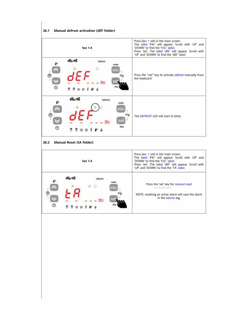
26.1 Manual defrost activation (dEF folder)
See 1-4
Press [esc + set] in the main screen. The label ‘PAr’ will appear. Scroll with ‘UP’ and ‘DOWN’ to find the ‘FnC’ label. Press ‘set’. The label ‘dEF’ will appear. Scroll with ‘UP’ and ‘DOWN’ to find the ‘dEF’ label
Press the "set" key to activate defrost manually from the keyboard
The DEFROST LED will start to blink.
26.2 Manual Reset (tA folder)
See 1-4
Press [esc + set] in the main screen. The label ‘PAr’ will appear. Scroll with ‘UP’ and ‘DOWN’ to find the ‘FnC’ label. Press ‘set’. The label ‘dEF’ will appear. Scroll with ‘UP’ and ‘DOWN’ to find the ‘TA’ label.
Press the ‘set’ key for manual reset - - - - - - - - -
NOTE: resetting an active alarm will save the alarm
in the alarms log.
<IMG INFO>
IMG INFO

26.3 Change On/OFF state (folder St)
See 1-4
Press [esc + set] in the main screen. The label ‘PAr’ will appear. Scroll with ‘UP’ and ‘DOWN’ to find the ‘FnC’ label. Press ‘set’. The label ‘dEF’ will appear. Scroll with ‘UP’ and ‘DOWN’ to find the ‘St’ label.
The label "OFF" will appear in the "St" folder if the device is ON, or "OFF", if the device is switched OFF locally or by remote
Press the set key to change state from OFF to On ------------------------------------------------------ or from On to OFF
IMG INFO
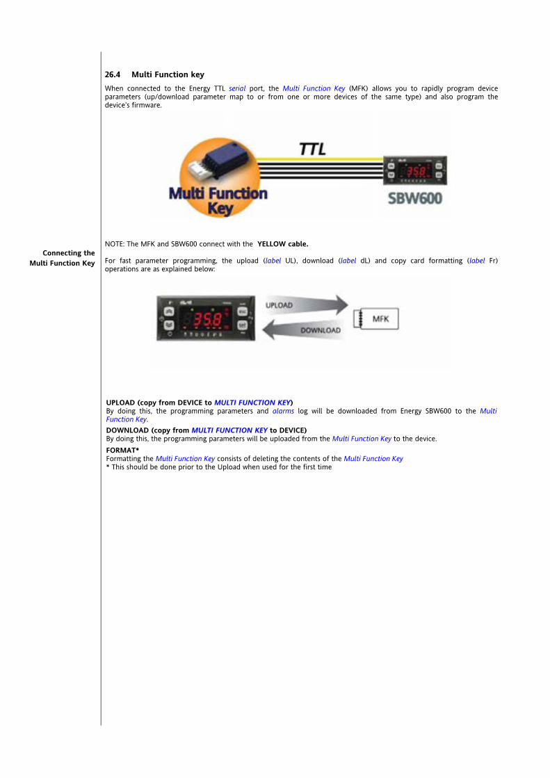
26.4 Multi Function key When connected to the Energy TTL serial port, the Multi Function Key (MFK) allows you to rapidly program device parameters (up/download parameter map to or from one or more devices of the same type) and also program the device’s firmware.
NOTE: The MFK and SBW600 connect with the YELLOW cable. For fast parameter programming, the upload (label UL), download (label dL) and copy card formatting (label Fr) operations are as explained below:
UPLOAD (copy from DEVICE to MULTI FUNCTION KEY) By doing this, the programming parameters and alarms log will be downloaded from Energy SBW600 to the Multi Function Key. DOWNLOAD (copy from MULTI FUNCTION KEY to DEVICE) By doing this, the programming parameters will be uploaded from the Multi Function Key to the device. FORMAT* Formatting the Multi Function Key consists of deleting the contents of the Multi Function Key * This should be done prior to the Upload when used for the first time
Connecting the Multi Function Key
<IMG INFO> 339,85 123,1 0 2 42,55 0 -1
<IMG INFO> 339,8 108,45 0 2 42,55 0 -1
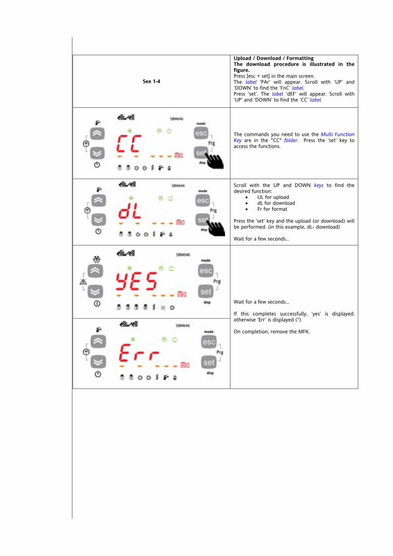
See 1-4
Upload / Download / Formatting The download procedure is illustrated in the figure. Press [esc + set] in the main screen. The label ‘PAr’ will appear. Scroll with ‘UP’ and ‘DOWN’ to find the ‘FnC’ label. Press ‘set’. The label ‘dEF’ will appear. Scroll with ‘UP’ and ‘DOWN’ to find the ‘CC’ label
The commands you need to use the Multi Function Key are in the "CC" folder. Press the ‘set’ key to access the functions.
Scroll with the UP and DOWN keys to find the desired function:
UL for upload dL for download Fr for format
Press the ‘set’ key and the upload (or download) will be performed. (in this example, dL- download) Wait for a few seconds...
Wait for a few seconds... If this completes successfully, ‘yes’ is displayed; otherwise ‘Err’ is displayed (°). On completion, remove the MFK.

26.4.1 Download from reset Connect the key with the device OFF. Download firmware At start up, if a compatible firmware is loaded into the MFK (the MFK can be prepared fro this with the Device Manager software), the new firmware is downloaded into the device. This happens as follows:
firmware verification/update (MFK led flashes) termination with successful programming (MFK on fixed) switch off the device
If a compatible firmware is not loaded into the MFK, no download takes place. If, on termination, the MFK led does not stay on fixed, the operation must be repeated as this means it failed. Download parameters On start up, if there is a compatible parameter map in the MFK, the programming parameters are loaded into the device;
lamp test completed…
Example A …dLY… appears on the display If the procedure terminates successfully.
Example B …dLn… appears on the display. If the procedure does not complete successfully (°)
In both cases, the device will be switched OFF locally (OFF appears on the display). When you press [DOWN] (°°), the device will operate: With the new map Example A With the previous map Example B Remove the Copy Card on completion (°°) see User Interface chapter, (folder Par/UI) local ON/OFF section Change On/OFF state (folder St) section
NOTES:
If the MFK is loaded with both a compatible firmware and a compatible parameter map, the firmware is downloaded first and then (after the device has been switched off and back on again manually) the parameter map.
The formatting function is ONLY REQUIRED FOR UPLOADING (**): o to use the Multi Function Key the first time (Multi Function Key that has never been used) and o to use the Multi Function Key with models that are not mutually compatible. o (**) a pre-programmed key supplied by Eliwell to DOWNLOAD parameters does not need to be
formatted. NOTE. Formatting can NOT be cancelled. after the download operation, the instrument will work with the newly loaded parameters map/firmware.
IMG INFO

<IMG INFO> 42,85 29,75 1 2 51 28 35
Remove the key on completion of the operation (°) If the string Err / dLn (download from reset) appears:
Check that the key is connected to the device Check the Multi Function Key - Energy SBW600 connection (check the TTL cable) Check that the key is compatible with the device Contact Eliwell technical support
26.5 Reset alarm log (folder EUr)
See 1-4
Press [esc + set] in the main screen. The label ‘PAr’ will appear. Scroll with ‘UP’ and ‘DOWN’ to find the ‘FnC’ label. Press ‘set’. The label ‘dEF’ will appear. Scroll with ‘UP’ and ‘DOWN’ to find the ‘EUr’ label.
Press the "set" key for 3 seconds [set]
The ‘YES’ label appears to indicate that the alarm log has been deleted
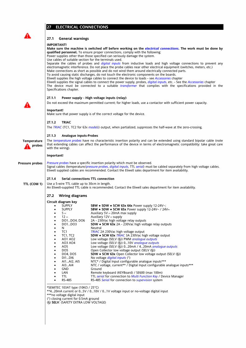
<IMG INFO> 30,6 43,9 1 2 51 -28,35 -1
<IMG INFO> 30,35 43,9 1 2 51 -28,35 -1
<IMG INFO> 30,35 43,9 1 2 51 -28,35 -1
27 ELECTRICAL CONNECTIONS
27.1 General warnings IMPORTANT! Make sure the machine is switched off before working on the electrical connections. The work must be done by qualified personnel. To ensure proper connections, comply with the following: Power supplies other than those specified can seriously damage the system. Use cables of suitable section for the terminals used. Separate the cables of probes and digital inputs from inductive loads and high voltage connections to prevent any electromagnetic interference. Do not place the probe cables near other electrical equipment (switches, meters, etc.) Make connections as short as possible and do not wind them around electrically connected parts. To avoid causing static discharges, do not touch the electronic components on the boards. Eliwell supplies the high voltage cables to connect the device to loads - see Accessories chapter Eliwell supplies the signal cables to connect the power supply, probes, digital inputs, etc. - See the Accessories chapter The device must be connected to a suitable transformer that complies with the specifications provided in the Specifications chapter.
27.1.1 Power supply - High voltage inputs (relay) Do not exceed the maximum permitted current; for higher loads, use a contactor with sufficient power capacity. Important! Make sure that power supply is of the correct voltage for the device.
27.1.2 TRIAC The TRIAC (TC1, TC2 for 63x models) output, when partialized, suppresses the half-wave at the zero-crossing.
27.1.3 Analogue inputs-Probes The temperature probes have no characteristic insertion polarity and can be extended using standard bipolar cable (note that extending cables can affect the performance of the device in terms of electromagnetic compatibility: take great care with the wiring). Important! Pressure probes have a specific insertion polarity which must be observed. Signal cables (temperature/pressure probes, digital inputs, TTL serial) must be cabled separately from high voltage cables. Eliwell supplied cables are recommended. Contact the Eliwell sales department for item availability.
27.1.4 Serial connections TTL connection Use a 5-wire TTL cable up to 30cm in length. An Eliwell-supplied TTL cable is recommended. Contact the Eliwell sales department for item availability.
27.2 Wiring diagrams Circuit diagram key
SUPPLY SBW SDW SCW 63x 64x Power supply 12-24Va; SUPPLY SBW SDW SCW 65x Power supply 12-24Va / 24Vc 5 c Auxiliary 5V c 20mA max supply 12 c Auxiliary 12V c supply DO1...DO4, DO6 2A - 230Vac high voltage relay outputs DO1...DO3 SDW SCW 63x 2A - 230Vac high voltage relay outputs N Neutral TC1 TRIAC 2A 230Vac high voltage output TC1, TC2 SDW SCW 63x TRIAC 3A 230Vac high voltage output AO1 AO2 Low voltage (SELV (§)) PWM analogue outputs AO3 AO4 Low voltage (SELV (§)) 0…10V analogue outputs AO5 Low voltage (SELV (§)) 0…20mA / 4…20mA analogue outputs DO5 Open Collector low voltage output (SELV (§)) DO4, DO5 SDW SCW 63x Open Collector low voltage output (SELV (§)) DI1...DI6 No voltage digital inputs (°) AI1...AI2, AI5 NTC* / Digital Input configurable analogue inputs*** AI3...AI4 NTC / voltage, current** / Digital Input configurable analogue inputs*** GND Ground LAN Remote keyboard (KEYBoard) / SE600 (max 100m) TTL TTL serial for connection to Multi Function Key / Device Manager RS-485 RS-485 Serial for connection to supervision system
-------------------------------------- *SEMITEC 103AT type (10KΩ / 25°C) **4…20mA current or 0…5V / 0…10V / 0…1V voltage input or no-voltage digital input ***no voltage digital input (°) closing current for 0.5mA ground (§) SELV: (SAFETY EXTRA LOW VOLTAGE)
Temperature probes
Pressure probes
TTL (COM 1)

27.2.1 Wiring Diagrams
646/C/S models
6 digital inputs [DI1…DI6] DI 4 high voltage digital outputs 2A 230Vac DO 6 analogue outputs AO:
o 1 high voltage [TC1] 2A 230Vac analogue output o 2 PWM analogue outputs [AO1, AO2] o 3 low voltage (SELV (§)) analogue outputs
2 outputs [AO3-4] 0-10V 1 output [AO5] 4…20mA/0…20mA
5 analogue inputs [AI1…AI5] 1 low voltage digital output (SELV (§)) [DO5]
o Open Collector
Model /S RS-485 on board
/C RTC supplied as standard TTL (COM 1) supplied as standard LAN connection to remote keyboard KEYB / SE600 (§) SELV: (SAFETY EXTRA LOW VOLTAGE)
SD646/C • SD646/C/SSC646/C • SC646/C/S
SE646
Supply
Supply
GNDGNDAI5
DI1 DI2 DI3 DI4 DI5 DI6 AO2
AI4AI2 AI3AI1AO
G 3 54
8765 1211109
RS-485
/S Modelsonly
+- G
RS-485
+- GG
SB646/CSB646/C/S
Supply
Supply
GND GND AI5
DI1DI2DI3DI4DI5DI6AO2
AI4 AI2AI3 AI1
AO RS-485
G3
/S Modelsonly
5 4 +- G
RS-485
+- GG
<IMG INFO>

655/C/S models
6 digital inputs [DI1…DI6] DI 5 high voltage digital outputs 2A 230Vac DO 5 analogue outputs AO:
o 2 PWM analogue outputs [AO1, AO2] o 3 low voltage (SELV (§)) analogue outputs
2 outputs [AO3-4] 0-10V 1 output [AO5] 4…20mA/0…20mA
5 analogue inputs [AI1…AI5] 1 low voltage digital output (SELV (§)) [DO5]
o Open Collector Model /S RS-485 on board
/C RTC supplied as standard TTL (COM 1) supplied as standard LAN connection to remote keyboard KEYB / SE600 (§) SELV: (SAFETY EXTRA LOW VOLTAGE)
SB655/CSB655/C/S
Supply
Supply
GND GND AI5
DI1DI2DI3DI4DI5DI6AO2
AI4 AI2AI3 AI1
AO
DO3
DO3
RS-485
G3
/S Modelsonly
5 4 +- G
RS-485
+- GG
SD655/C • SD655/C/SSC655/C • SC655/C/S
SE655
Supply
Supply
GNDGNDAI5
DI1 DI2 DI3 DI4 DI5 DI6 AO2
AI4AI2 AI3AI1
8765 1211109
6
6
RS-485
/S Modelsonly
+- G
RS-485
+- GG
AO
G 3 54
<IMG INFO>
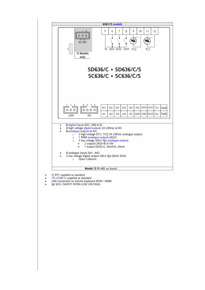
636/C/S models
6 digital inputs [DI1…DI6] DI 3 high voltage digital outputs 2A 230Vac DO 6 analogue outputs AO:
o 2 high voltage [TC1, TC2] 3A 230Vac analogue output o 1 PWM analogue outputs [AO1] o 3 low voltage (SELV (§)) analogue outputs
2 outputs [AO3-4] 0-10V 1 output [AO5] 4…20mA/0…20mA
5 analogue inputs [AI1…AI5] 2 low voltage digital output (SELV (§)) [DO4, DO5]
o Open Collector
Model /S RS-485 on board
/C RTC supplied as standard TTL (COM 1) supplied as standard LAN connection to remote keyboard KEYB / SE600 (§) SELV: (SAFETY EXTRA LOW VOLTAGE)
DO3
SD636/C • SD636/C/SSC636/C • SC636/C/S
Supply
Supply
GNDGNDAI5
DI1 DI2 DI3 DI4 DI5 DI6 DO4
AI4AI2 AI3AI1
8765 1211109
RS-485
/S Modelsonly
+- G
RS-485
+- GG
AO
G 3 54

632 model
6 digital inputs [DI1…DI6] DI 3 high voltage digital outputs 2A 230Vac DO 2 analogue outputs AO:
o 2 PWM analogue outputs [AO1, AO2]
3 analogue inputs [AI1…AI5] 1 low voltage digital output (SELV (§)) [DO5]
o Open Collector
TTL (COM 1) supplied as standard LAN connection to remote keyboard KEYB or SB/SC/SD600 (§) SELV: (SAFETY EXTRA LOW VOLTAGE)
SE632
Supply
Supply
GNDGNDAI5
DI1 DI2 DI3 DI4 DI5 DI6 AO2
NC NCAI2 NCAI1
87 109
<IMG INFO> 339,9 273,4 0 2 72,25 0 -1

Energy SB-SD-SCW600 208/240
27.2.2 Example of low voltage input/output connection
SBW600 - Example of low voltage input/output connection SDW SCW SE 600 Example identical
Analogue outputs AO see chapter System configuration (folder Par/CF) paragraph Configuration of analogue outputs Digital output D05 see Digital Output Configuration LAN : see connecting remote keyboard /SE600
27.2.2.1 Example of AO1 / AO2 connection
Example of SBW600 (AO1) connection with 1 fan module CFS PWM or EXP211
Example of SBW600 (AO2) connection with 1 fan module CFS PWM or EXP211
SDW SCW SE 600 Example identical SDW SCW SE 600 Example identical
LN
AI5 AI4 AI3GND
DI5 DI4 DI3DI6AO2AO1SUPPLY 12cc
SUPPLY 5VccDO5 GND AI2
DI2 DI1 AO
G 4
AI15 3
SB646/C/S
<IMG INFO> <IMG INFO>

27.2.2.2 Example of AO3 - AO4 connection
Example of SBW600 (AO3-AO4) connection with 1 fan module CFS 0-10V
SDW SCW SE 600 Example identical
Analogue output Terminal no. description AO3 3 0-10V AO3 G GND AO4 4 0-10V AO4 G GND
27.2.2.3 Example of AO5 connection Example of SB600 (AO5) connection with 1 fan module CFS
0…20mA / 4…20mA SDW SCW SE 600 Example identical
Analogue output Terminal no. description AO5 5 0…20mA / 4…20mA AO5 G GND
<IMG INFO> 225 7
<IMG INFO>

27.2.2.4 Example of DO5 connection
27.2.3 Example of connection of high voltage outputs
Example of model with TRIAC 646 models - Example of connection of high voltage outputs
27.3 Examples of network connections
27.3.1 Example of connection SBW600 – SE600
collegamento SBW600 –> SE600
27.3.2 Esempio collegamento SDW600/SCW600 – SE600
collegamento SDW600 / SCW600 –> SE600
e of SBW600 connection with W SCW SE 600 Example identi
L
789101112 6 5
DO1 DO2 DO4 DO4DO3 NTC1 TC1
SE646
Supply
Supply
GNDGNDAI5
DI1 DI2 DI3 DI4 DI5 DI6 AO2
AI4AI2 AI3AI1AO
G 3 54
8765 1211109
SB646/CSB646/C/S
Supply
Supply
GND GND AI5
DI1DI2DI3DI4DI5DI6AO2
AI4 AI2AI3 AI1
AO RS-485
G3
/S Modelsonly
5 4 +- G
RS-485
+- GG
BLACK GND
RED 12Vdc
BLUE SIGNAL

27.4 SKP 10 Remote Terminal 32x74
SKP 10
Terminal SBW600 SDW600 SCW600
Terminal SKP 10 description
1 1 GND / black 2 2 Signal / blue
LAN
3 3 12V~ power supply from base module
27.4.1 Example of connection SCW600 – SKP 10 collegamento SCW600 –> SKP 10
SKP 10
BLACK
BLUE
RED
SC646/C • SC646/C/S
Supply
Supply
GNDGNDAI5
DI1 DI2 DI3 DI4 DI5 DI6 AO2
AI4AI2 AI3AI1AO
G 3 54
8765 1211109
RS-485
/S Modelsonly
+- G
RS-485
+- GG
BLACK GND
RED 12Vdc
BLUE SIGNAL
SKP 10
BLACK
BLUE
RED
<IMG INFO>
SD646/C • SD646/C/SSC646/C • SC646/C/S
Supply
Supply
GNDGNDAI5
DI1 DI2 DI3 DI4 DI5 DI6 AO2
AI4AI2 AI3AI1AO
G 3 54
8765 1211109
RS-485
/S Modelsonly
+- G
RS-485
+- GG
BLACK GND
RED 12Vdc
BLUE SIGNAL
SE646
Supply
Supply
GNDGNDAI5
DI1 DI2 DI3 DI4 DI5 DI6 AO2
AI4AI2 AI3AI1AO
G 3 54
8765 1211109
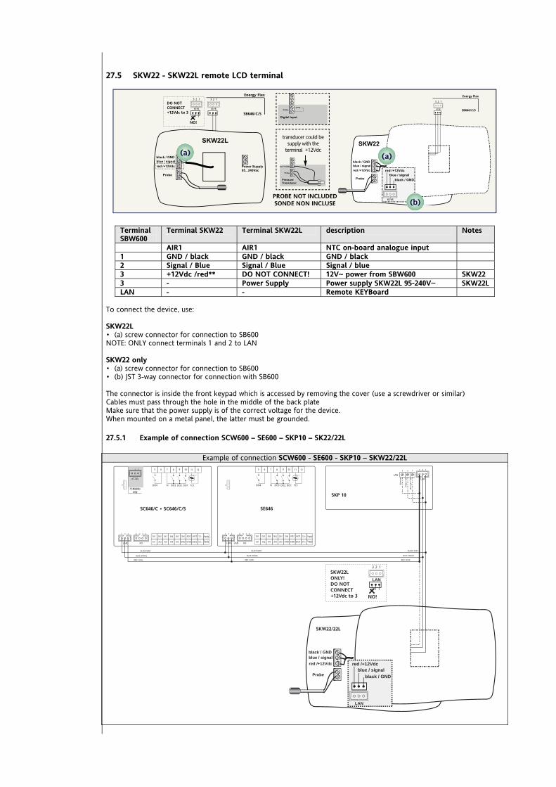
27.5 SKW22 - SKW22L remote LCD terminal
Terminal SBW600
Terminal SKW22 Terminal SKW22L description Notes
AIR1 AIR1 NTC on-board analogue input 1 GND / black GND / black GND / black 2 Signal / Blue Signal / Blue Signal / blue 3 +12Vdc /red** DO NOT CONNECT! 12V~ power from SBW600 SKW22 3 - Power Supply Power supply SKW22L 95-240V~ SKW22L LAN - - Remote KEYBoard
To connect the device, use: SKW22L • (a) screw connector for connection to SB600 NOTE: ONLY connect terminals 1 and 2 to LAN SKW22 only • (a) screw connector for connection to SB600 • (b) JST 3-way connector for connection with SB600 The connector is inside the front keypad which is accessed by removing the cover (use a screwdriver or similar) Cables must pass through the hole in the middle of the back plate Make sure that the power supply is of the correct voltage for the device. When mounted on a metal panel, the latter must be grounded.
27.5.1 Example of connection SCW600 – SE600 – SKP10 – SK22/22L
Example of connection SCW600 - SE600 - SKP10 – SKW22/22L
<IMG INFO>
SC646/C • SC646/C/S
Supply
Supply
GNDGNDAI5
DI1 DI2 DI3 DI4 DI5 DI6 AO2
AI4AI2 AI3AI1AO
G 3 54
8765 1211109
RS-485
/S Modelsonly
+- G
RS-485
+- GG
BLACK GND
RED 12Vdc
BLUE SIGNAL
SE646
Supply
Supply
GNDGNDAI5
DI1 DI2 DI3 DI4 DI5 DI6 AO2
AI4AI2 AI3AI1AO
G 3 54
8765 1211109
BLACK GND
RED 12Vdc
BLUE SIGNAL
BLACK GND
RED 12Vdc
BLUE SIGNAL
SKP 10
BLACK
BLUE
RED
SKW22/22L
black / GNDblue / signalred /+12Vdc
Probe black / GNDblue / signal
red /+12Vdc
LAN
LAN
SKW22L ONLY!DO NOTCONNECT+12Vdc to 3 NO!
<IMG INFO>

Energy SB-SD-SCW600 213/240
28 MECHANICAL ASSEMBLY SBW600 – SKP 10 The instrument is intended for panel mounting (see diagram). Make a 29x71 mm hole and insert the instrument; secure it with the special brackets provided. Do not mount the device in damp and/or dirt-laden areas; it is suitable for use in places with ordinary or normal levels of pollution. Keep the area around the device cooling slots adequately ventilated. The TTL serial is on the left side of the device.
Example of panel-mounted SBW600 – SKP 10 Panel-mounted SBW600 – SKP 10
The images refer to SBW600
IMG INFO
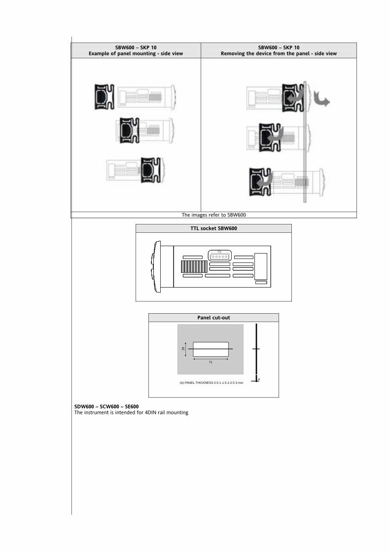
SBW600 – SKP 10
Example of panel mounting - side view SBW600 – SKP 10
Removing the device from the panel - side view
The images refer to SBW600
TTL socket SBW600
Panel cut-out
SDW600 – SCW600 – SE600 The instrument is intended for 4DIN rail mounting
<IMG INFO>
<IMG INFO>
A(A) PANEL THICKNESS 0.5-1-1.5-2-2.5-3 mm
71
29
<IMG INFO> 150,1
105,95 02
IMG INFO

Energy SB-SD-SCW600 215/240
29 TECHNICAL DATA
29.1 General specifications
29.1.1 SB600 General specifications
Standard Min. Max. Power supply voltage Models 63x 64x 12-24V~ Power supply voltage Models 65x 12-24V~ /24Vc Power supply frequency 50Hz/60Hz --- --- Consumption SBW600 SDW600 SCW600 6VA / 4W --- --- Consumption SE600 5VA /3.5W --- --- Insulation class 2 --- --- Working temperature 25°C -10°C 55°C Ambient operating humidity (non-condensing) 30% 10% 90% Storage temperature 25°C -20°C 85°C Ambient storage humidity (non-condensing) 30% 10% 90%
Classification The product complies with the following European Community Directives
Directive 2006/95/EC Directive 89/108/EC
and complies with the following harmonised regulations: EN 60730-2-6 EN 60730-2-9
Use operating (not safety) device for incorporation
Mounting panel or on DIN Omega bar support
Type of action 1.B 1.Y Pollution class 2 Overvoltage category II Nominal pulse voltage 2500V Digital outputs
refer to the label on the device.
Fire resistance category D Software class A

<IMG INFO> 56,75 43,9 1 2 51 -28,35 -1
29.2 I/O features
Type Folder Description Model
Digital inputs DI1 DI2 DI3 DI4 DI5 DI6
6 no-voltage digital inputs Closing current for ground: 0.5mA All models
DO1 DO2 DO3 DO4*
4 relays 2A 250V~; *For 636 models D04 is available as Open Collector output
All models Digital outputs High voltage
DO6 1 relay 2A 250V~; 65x Models
DO4* 1 output Open Collector **Max. current 35mA @12Vcc 63x models Open Collector low voltage
(SELV) digital output DO5 1 output Open Collector **Max. current 35mA @12Vcc All models
Analogue output High voltage
TC1
1 - 2A TRIAC, max 250V~ Resolution 1% Contactors may NOT be installed downstream from the Triac
64x Models
TC1 TC2 = AO2
2 - 3A TRIAC, max 250V~ Resolution 1% Contactors may NOT be installed downstream from the Triac
63x Models
Analogue outputs PWM/Open Collector low voltage (SELV)
AO1 AO2
2 outputs PWM / Open Collector PWM resolution: 1% PWM / Open Collector Nominal range 0…16.9Vc (12V~ rectified) Closing at 12Vc
**Max. current 35mA (min. load 340Ohm @12Vcc)
All models Except
Models 63x Where AO2 = TC2
(TRIAC)
AO3 AO4
2 outputs 0-10V 2% full scale accuracy Resolution 1% output 0…10Vcc, max 28mA*** @10V
(min. load resistance 360Ohm).
All models
Analogue outputs low voltage (SELV)
AO5
1 output 4..20mA / 0…20mA 2% full scale accuracy Resolution 1% output 0/4…20mA max. load (max load
resistance 350Ohm)***
All models
Analogue inputs
AI1 AI2
AI3 AI4
AI5
3 configurable inputs: a) temperature NTC 103AT 10kΩ,
measurement range -50C 99.9C; b) no voltage digital input
2 configurable inputs:
a) temperature NTC 103AT 10kO, measurement range -50C 99.9C;
b) current input 4...20 mA /voltage input 0-10V/0-5V/0-1V
measurement range -50.0 +99.9; accuracy: 1% full scale (2% full scale for 0-1V voltage input) Resolution: (a) 0.1°C (b) 0.1°C/bar Input impedance (b):
0-10V and 0-5V: 21KOhm 0-1V: 10KOhm 4…20mA: 100Ohm c) no voltage digital input
All models
* For 63x models DO4 is an Open collector, TC2 equals to AO2 (TC2=AO2) – see System configuration (folder PAr/CL-Cr-CF) chapter ** Outputs AO1, AO2 and DO5 (typically connected to the device's auxiliary 12V output) cannot deliver more than 70mA total). Any other loads connected to the same 12Vc auxiliary output must also be taken into account If the SKP 10 keypad is connected to the device, the current becomes 55mA *** outputs AO3, AO4 and AO5 cannot deliver more than 40mA total.

29.3 Mechanical specifications
1 8-way high voltage male connector For use in combination with the supplied female connector
All models
1 20-way snap-on low voltage connector To be used with COLV0000E0100
All models
1 JST 3-way remote keyboard connector To be used with COLV000033200
All models
1 JST 4 -way connector To be used with COLV000042100
All models
Terminals and connectors
1 JST 3-way connector To be used with COLV000035100
Models /S
Housing Housing: PC+ABS plastic resin with V0 flammability rating
29.4 Display and LEDS
Display and LEDS 4 digits or 3 digits + sign; 18 LEDs
All models except SCW600 SE600
Keys UP DOWN set esc 4 keys All models
except SCW600 SE600
29.5 Serial
TTL 1 TTL serial for connection to
CopyCard (MFK) or Personal Computer via interface module
All models
Serial
RS-485 RS-485 opto-isolated serial Models /S
29.6 Transformer The instrument must be connected to a suitable current transformer with the following features:
Primary voltage: depending on requirements of individual device and/or country of installation Secondary voltage: 12V~ Power supply frequency: 50/60Hz Rating: 6VA min. (/S models), 5VA (all other models)

29.7 Mechanical dimensions
Length (L) mm Depth (d) mm Height (H) mm Notes
Front keypad 76.4 // 35 (+0.2mm)
Front (cover) SDW600 SC600 SE600
70 // 45 (+0.2mm)
Dimensions SB600 86 76 connectors excluded 26
Dimensions SDW600 SCW600 SE600
70.2
61.6 56.4 from Din bar to
cover
87 4DIN
Hole for panel mounting 71 // 29 (+0.2mm/ -0.1mm)
SBW600
SDW600 / SCW600 – SE600
74mm
70mm
28m
m
32m
m
29m
m
71mm76m
m
76mm
56.4mm
5.2mm
87m
m
70.2mm61.6mm
43.6mm
70.2mm
SD SC SE

SKP 10
29.8 Permitted use This product is used to control centralised air-conditioning units For safety reasons the instrument must be installed and used in accordance with the instructions supplied. Users must not be able to access parts with dangerous voltage levels under normal operating conditions. The device must be suitably protected from water and dust according to the specific application and only be accessible using special tools (except for the front keypad). The device can be fitted to refrigeration equipment for household and/or similar use. It has been tested and in safety terms, conforms to applicable harmonized European standards.
29.8.1 Unintended Use The use of the unit for applications other than those described above is forbidden. It should be noted that the relay contacts supplied with the device are functional and therefore may be subject to fault. Any protection devices required to comply with product requirements or dictated by common sense due for obvious safety reasons should be installed externally.
29.9 Responsibility and Residual Risks Eliwell shall not be held liable for any damage incurred as a result of: installation/use other than those intended, and, in particular, failure to comply with the safety instructions specified
by applicable regulations and/or provided in this document; use with equipment which does not provide adequate protection against electric shocks, water and dust under the
effective conditions of installation; use with equipment which permits access to hazardous parts without the use of tools; installation/use with equipment which does not comply with current regulations and legislation.
29.10 Disclaimer This document is exclusive property of Eliwell Controls srl. and cannot be reproduced and circulated unless expressly authorized by Eliwell Controls srl Although all possible measures have been taken by Eliwell Controls srl l. to guarantee the accuracy of this document, it does not accept any responsibility arising out of its use.
74mm74mm
70mm70mm
28mm
28mm
32mm
32mm
29mm
29mm
71mm71mm
30mm
30mm
30mm30mm
<IMG INFO>
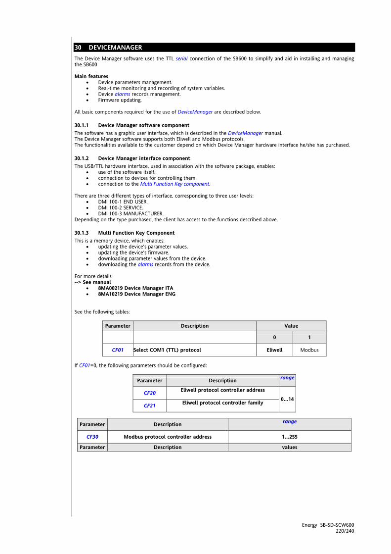
Energy SB-SD-SCW600 220/240
30 DEVICEMANAGER The Device Manager software uses the TTL serial connection of the SB600 to simplify and aid in installing and managing the SB600 Main features
Device parameters management. Real-time monitoring and recording of system variables. Device alarms records management. Firmware updating.
All basic components required for the use of DeviceManager are described below.
30.1.1 Device Manager software component The software has a graphic user interface, which is described in the DeviceManager manual. The Device Manager software supports both Eliwell and Modbus protocols. The functionalities available to the customer depend on which Device Manager hardware interface he/she has purchased.
30.1.2 Device Manager interface component The USB/TTL hardware interface, used in association with the software package, enables:
use of the software itself. connection to devices for controlling them. connection to the Multi Function Key component.
There are three different types of interface, corresponding to three user levels:
DMI 100-1 END USER. DMI 100-2 SERVICE. DMI 100-3 MANUFACTURER.
Depending on the type purchased, the client has access to the functions described above.
30.1.3 Multi Function Key Component This is a memory device, which enables:
updating the device's parameter values. updating the device's firmware. downloading parameter values from the device. downloading the alarms records from the device.
For more details --> See manual
8MA00219 Device Manager ITA 8MA10219 Device Manager ENG
See the following tables:
Parameter Description Value
0 1
CF01 Select COM1 (TTL) protocol Eliwell Modbus
If CF01=0, the following parameters should be configured:
Parameter Description range
CF20 Eliwell protocol controller address
CF21 Eliwell protocol controller family
0…14
Parameter Description range
CF30 Modbus protocol controller address 1…255
Parameter Description values

Parameter Description range
CF31 Modbus protocol baudrate
0=1200 baud 1=2400 baud 2=4800 baud 3=9600 baud 4=19200 baud 5=38400 baud (maximum speed when
using DeviceManager) 6=58600 baud 7=115200 baud
CF32 Modbus protocol parity 0= STX 1= EVEN 2= NONE 3= ODD

Energy SB-SD-SCW600 222/240
31 SUPERVISION The TTL serial - referred to also as COM1 - can be used to configure the device, parameters, states, and variables using the Modbus protocol. Study the following tables:
Parameter Description value
0 1
CF01 Select COM1 (TTL) protocol Eliwell Modbus
If CF01=0, the following parameters should be configured:
Parameter Description range
CF20 Eliwell protocol controller address
CF21 Eliwell protocol controller family 0…14
Parameter Description range
CF30 Modbus protocol controller address 1…255
Parameter Description values
CF31 Modbus protocol Baudrate
0=1200 baud 1=2400 baud 2=4800 baud 3=9600 baud 4=19200 baud 5=38400 baud (maximum speed when
using DeviceManager) 6=58600 baud 7=115200 baud
31.1 Configuration with Modbus RTU Modbus is a client/server protocol for communication between network linked devices. Modbus devices communicate using a master-slave technique in which a single device (the master) can send messages. All other devices in the network (slaves) respond by returning the data required to the master or executing the action indicated in the message received. A slave is defined as a device connected to a network that processes information and sends the results to a master using the Modbus protocol. The master can send messages to individual slaves or to the entire network (broadcast) whilst slaves can only reply to messages received individually from the master. The Modbus standard used by Eliwell uses RTU coding for data transmission.
31.1.1 Data format (RTU) The data coding model used defines the structure of messages sent to the network and the way in which the information is decoded. The type of coding selected is generally based on specific parameters (baud rate, parity, etc)*** and some devices only support specific code models. However, the same model must be used for all devices connected to a Modbus network. The protocol used the RTU binary method with the following bytes: 8 bits for data, even parity bit (not configurable), 1 stop bit. ***configured with parameters CF30, CF31 - see table at start of paragraph NOTE: transmission speed must be set at 9600 baud. The device is fully configurable via parameter settings They can be modified with:
the instrument’s keyboard Multi Function key by sending data via the Modbus protocol straight to individual instruments, or via broadcast, using the
address 0 (broadcast)

The connection diagram when using Modbus is shown below
ModBus - device connection diagram Single via TTL
ModBus - multiple devices connection diagram Via RS485
PC / Interface connection RS232 cable Device / Bus Adapter connection TTL cable with 5 way connector (30cm) (available
with other sizes/lengths) Bus adapter BA150 Bus Adapter / Interface connection RS485 cable
shielded and twisted (example: Belden model 8762 cable)
31.1.2 Modbus commands available and data areas The commands implemented are:
Length restrictions
maximum length in bytes of messages sent to device 30 BYTES
maximum length in bytes of messages received by device 30 BYTES Multiple read of 2 real setpoints
Field Decimal Hex Dimension Device address (slave): 1 0x01 byte Read command code: 3 0x03 byte Start address: 975 0x03CF Word Number of registers (words) to read: 3 0x0003 Word
Configuration of COOL operating mode Write value 8 to word for remote commands at address h2FC
Field Decimal Hex Dimension Device address (slave): 1 0x01 byte Write command code: 10 0x0A byte Write address: 764 0x02FC Word Number of words to write: 1 0x0001 Word Number of bytes (No. words x 2): 2 0x02 Word Value (word) to write: 8 0x0008 Word
At the end of this operation, the device will switch to COOL mode (if enabled). Configuration of ON/OFF operating mode Write value 128 to word for remote commands at address h2FC At the end of this operation, the device will toggle the On/Off state (if enabled).
Modbus command Description of command 3 Read multiple registers on Client side 16 Write multiple registers on Client side 43 Read device ID
DESCRIPTION Manufacturer ID Model ID Version ID
<IMG INFO>

The Ram variables that can be monitored and commands available are listed below. Commands available:
Manual alarm reset Change operating mode (Heat, Cool and St-By) Switch device on/off Enable defrost
Additional operations can be performed by following specific procedures:
read alarm log change/set time reset running time of compressor and pump outputs
Details for read alarm log The alarm log is saved in the EEPROM in a circular buffer composed of 7-byte records formatted as follows
Byte bit index Data Values 0 Bit 0 Alarm record flag free Must always be 0 1 Bit 1 Alarm state 0 = alarm reset; 1 = alarm current 2 Bit 2 Automatic reset alarm 0 = automatic reset; 1 = manual reset 3 - 4 - 5 - 6 -
0
7 -
Not used
0 Bit 0 1 Bit 1 2 Bit 2 3 Bit 3 4 Bit 4 5 Bit 5
Start of alarm minute 0÷59 = minutes >59 = undetermined value
6 Bit 0
1
7 Bit 1 0 Bit 2 1 Bit 3 2 Bit 4 3 Bit 5
End of alarm minute 0÷59 = minutes >59 = undetermined value
4 Bit 0 5 Bit 1 6 Bit 2
2
7 Bit 3 0 Bit 4
Start of alarm hour 0÷23 = hours >23 = undetermined value
1 Bit 0 2 Bit 1 3 Bit 2 4 Bit 3 5 Bit 4
End of alarm hour 0÷23 = hours >23 = undetermined value
6 Bit 0
3
7 Bit 1 0 Bit 2 1 Bit 3 2 Bit 4
Start of alarm day 1÷31 = day 0 or >31 = undefined value
3 Bit 0 4 Bit 1 5 Bit 2 6 Bit 3
4
7 Bit 4
End of alarm day 1÷31 = day 0 or >31 = undefined value
0 Bit 0 1 Bit 1 2 Bit 2 3 Bit 3
Start of alarm month 0÷23 = hours >23 = undetermined value
4 Bit 0 5 Bit 1 6 Bit 2
5
7 Bit 3
End of alarm month 0÷23 = hours >23 = undetermined value
0 Bit 0 1 Bit 1 2 Bit 2 3 Bit 3 4 Bit 4 5 Bit 5 6 Bit 6
6
7 Bit 7
Alarm code 0÷99 = alarm code >99 Not allowed
To identify the index of the first record, read variable PntStorAll at address h83A8

To identify the number of records present, read variable NumStorAll at address h83A9 Address 0x83A8 => data: 0x0027 = Index of first record (most recent); Address 0x83A9 => data: 0x0027 = number of records (39); To calculate the address of the most recent record: Address EU00 = 51712 + (N-1)x7 = 51712 + 17x7 = 51832 (0xCA77) Read EU00 TX: 01, 03, CA, 77, 00, 07, 8B, CA. RX: 01, 03, 0E, 00, 82, 00, DD, 00, CF, 00, FE, 00, 04, 00, 06, 00, 3C, 9B, 13. Address 0xCA77 => data: 0x0082 = Byte 0 of alarms log; Address 0xCA78 => data: 0x00DD = Byte 1 of alarms log; Address 0xCA79 => data: 0x00CF = Byte 2 of alarms log; Address 0xCA7A => data: 0x00FE = Byte 3 of alarms log; Address 0xCA7B => data: 0x0004 = Byte 4 of alarms log; Address 0xCA7C => data: 0x0006 = Byte 5 of alarms log; Address 0xCA7D => data: 0x003C = Byte 6 of alarms log; Alarm record flag free = b 0 = 0 Alarm state = b 1 = 1 Automatic reset alarm = b 0 = 0 Not used = b 10000 = free Start of alarm minute = b 011101 = 29 End of alarm minute = b 111111 = 63 (undefined) Start of alarm hour = b 01100 = 12 End of alarm hour = b 11111 = 31 (undefined) Start of alarm day = b 10011 = 19 End of alarm day = b 00000 = 0 (undefined) Start of alarm month = b 0110 = 6 End of alarm month = b 0000 = 0 (undefined) Alarm code = b 00111100 = 60 The result shows that on EU00 there is an Er60 that started on 19/06 at 12.19 and which is still active. To read EU01, the address is determined as follows Address EU01 = Address EU00 - 7 = 51832 - 7 = 51825 To read EU02 continue by subtracting 7 fromaddress EU01 and so on… NOTE: The minimum limit is address 51712 (hCA00) after which, if there are still alarms to be read, you must start again from address 52404 (hCCB5) (the buffer is circular and after the 99th record it writes over the old ones). Details for reading, modifying, setting the time To write the hour, address the structure DataWrite at address h82F4 Write the seconds byte last! Example: Set time h11:33 on 28/03/2007
Field Address Decimal Hex Dimension 0: seconds H82F4 0 0x0000 bytes 1: minutes H82F5 33 0x0021 bytes 2: hours H82F6 11 0x000B bytes 3: dayweek H82F7 - - bytes 4: daymonth H82F8 28 0x001C bytes 5: month H82F9 3 0x0003 bytes 6: year H82FA 7 0x0007 bytes
NOTE: Write the seconds byte last! Write sequence: Write 6 words of 46, 12, 0, 19, 6, 8 at the address H82AF5. Write a word of 00 at the address H82AF4 Details for resetting the running time To read and/or clear running time, address the counters in the device's EEPROM and RAM STCPOreFunz[0] to the address h3AB Running time CP1 (in Ram) STCPOreFunz[1] to the address h3AC Running time CP2 (in Ram) STPMOreFunz[0] to the address h3B3 Running time P1 (in Ram) STPMOreFunz[1] to the address h3B4 Running time P2 (in Ram) EE_OreFunzCP0 to the address h4F20 Running time CP1 (in EEPROM) EE_OreFunzCP1 to the address h4F22 Running time CP2 (in EEPROM) EE_OreFunzP0 to the address h4F38 Running time P1 (in EEPROM) EE_OreFunzP1 to the address h4F38 Running time P2 (in EEPROM)

Multiple reading of running time CP to the RAM address h3AB The full command to be sent to the device will therefore be: Address 0x03AB => data: 0x0065 = 101 hours running time CP1; Address 0x03AC => data: 0x0000 = not used Address 0x03AD => data: 0x0001 = 1 hours running time CP2; Clear time CP1 (in RAM and EEPROM) Write 0 for running time CP at RAM address h3AB Write 0 for running time CP at EEPROM address h4F20 Variables: See Parameters chapter (PAr), Client table
31.2 Configuration of device address The Device Number in a ModBus message is defined by the parameter CF63 - see table at beginning of this section The address 0 is used for broadcast messages that all slaves recognize. Slaves do not reply to broadcast messages.
31.2.1 Configuration of parameter addresses The list of addresses is given in the Parameters chapter under the section headed "Parameters Table / visibility, ADDRESS column (parameter addresses) and VIS PAR ADDRESS (parameter visibility addresses)
31.2.2 Configuration of variable / state addresses The list of addresses is given in the Parameters chapter, under the section headed Client Table ADDRESS column

32 ANNEXE A – MODELS AND ACCESSORIES
32.1 Models
32.1.1 Models SBW SDW SCW600 SE600
mod
el
item
num
ber
Volt
age-
free
di
gita
l inp
uts
Dig
ital o
utpu
ts
Hig
h vo
ltag
e
Anal
ogue
out
put
Hig
h vo
ltag
e
Anal
ogue
out
puts
PW
M S
afe
volt
age
(SEL
V)
Anal
ogue
out
puts
Sa
fe v
olta
ge
(SEL
V)
Anal
ogue
inpu
ts
Safe
vol
tage
(S
ELV)
Dig
ital o
utpu
t
Ope
n Co
llect
or
RS-4
85 s
eria
l
(DI1…DI6) (DO1…DO4) (+ DO6) (TC1) (AO1-AO2)
(AO3-AO5)
(AI) (DO5) /S
SBW646/C/S SB641235W2400 6 4 1 2 3 5 1 YES
SBW646/C SB641235W1400 6 4 1 2 3 5 1 NO
SDW646/C/S SD641235W2400 6 4 1 2 3 5 1 YES
SDW646/C SD641235W1400 6 4 1 2 3 5 1 NO
SCW646/C/S SC641235W2400 6 4 1 2 3 5 1 YES
SCW646/C SC641235W1400 6 4 1 2 3 5 1 NO
SDW655/C/S SD650235W2400 6 5 // 2 3 5 1 YES
SDW655/C SD650235W1400 6 5 // 2 3 5 1 NO
SCW655/C/S SC650235W2400 6 5 // 2 3 5 1 YES
SCW655/C SC650235W1400 6 5 // 2 3 5 1 NO
SE632 SE64123510400 6 3 // 2 // 3 1 NO
SE646 SE64123510400 6 4 1 2 3 5 1 NO
SE655 SE65023510400 6 5 // 2 3 5 1 NO
NOTE:
SBW646 Power supply 12…24Va
SBW655 Power supply 12…24Va / 24Va TTL supplied as standard /C indicates the presence of real-time clock (RTC) /S indicates the presence of on-board RS485 SELV: SAFETY EXTRA LOW VOLTAGE

32.1.2 SBW SDW636 models 2 TRIAC
mod
el
item
num
ber
Volt
age-
free
di
gita
l inp
uts
Dig
ital o
utpu
ts
Hig
h vo
ltag
e
Anal
ogue
out
put
Hig
h vo
ltag
e
Anal
ogue
out
puts
PW
M S
afe
volt
age
(SEL
V)
Anal
ogue
out
puts
Sa
fe v
olta
ge
(SEL
V)
Anal
ogue
inpu
ts
Safe
vol
tage
(S
ELV)
Dig
ital o
utpu
t
Ope
n Co
llect
or
RS-4
85 s
eria
l
(DI1…DI6) (DO1 DO2 DO3)
(TC1, TC2) (A01) (AO3-AO5)
(AI) (DO4, DO5) /S
SDW636/C/S SD632135W2400 6 3 2 1 3 5 2 YES
SDW636/C SD632135W1400 6 3 2 1 3 5 2 NO
SCW36/C/S SC632135W2400 6 3 2 1 3 5 2 YES
SCW636/C SC632135W1400 6 3 2 1 3 5 2 NO
NOTE: TC2 equals to AO2 (TC2=AO2) – see System configuration (folder PAr/CL-Cr-CF) chapter TTL supplied as standard /C indicates the presence of the RTC - Real Time Clock /S indicates the presence of on-board RS485 SELV: SAFETY EXTRA LOW VOLTAGE
32.1.3 Remote terminals
Mod
el
Code
Mou
ntin
g
Dim
ensi
ons
Dis
play
Anal
ogue
Inpu
ts
Safe
vol
tage
(S
ELV)
Pow
er s
uppl
y
SKP10 SKP1000000000 panel 74x32x30mm LED / 4 digit - From base
SKW22 SKW2200000000 wall 137x96.5x31.3mm LCD
1 onboard NTC 1 V/I
configurable input
12V~ from base
SKW22L SKW22L0000H00 wall 137x96.5x31.3mm LCD backlit
1 onboard NTC
1 configurable
V/I input
95-240V~ from base
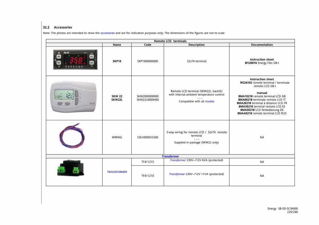
Energy SB-SD-SCW600 229/240
32.2 Accessories Note: The photos are intended to show the accessories and are for indication purposes only. The dimensions of the figures are not to scale
Remote LCD terminals Name Code Description Documentation
SKP10 SKP1000000000 32x74 terminal Instruction sheet 8FI20016 Energy Flex GB-I
SKW 22 SKW22L
SKW2000000000 SKW22L0000H00
Remote LCD terminal (SKW22L: backlit) with internal ambient temperature control
- - - Compatible with all models
Instruction sheet 9IS24102 remote terminal / terminale
remoto LCD GB-I
manual 8MA10218 remote terminal LCD GB 8MA00218 terminale remoto LCD IT
8MA20218 terminal à distance LCD FR 8MA30218 terminal remoto LCD ES 8MA50218 LCD ferbedienung DE
8MAA0218 remote terminal LCD RUS
WIRING C0LV000033200
3-way wiring for remote LCD / 32x74 remote terminal
- - - Supplied in package (SKW22 only)
NA
Transformer
TF411215 Transformer 230V~/12V 6VA (protected) NA
TRANSFORMER TF411210 Transformer 230V~/12V 11VA (protected)
NA
IMG INFO
<IMG INFO> 105,5 63,85 0 2 18,75 -55,35 -1
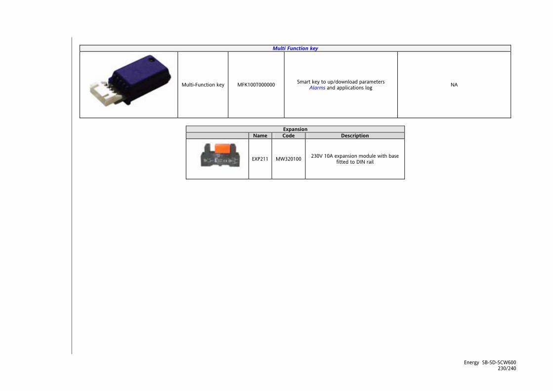
Energy SB-SD-SCW600 230/240
Multi Function key
Multi-Function key MFK100T000000 Smart key to up/download parameters Alarms and applications log NA
Expansion
Name Code Description
EXP211 MW320100 230V 10A expansion module with base fitted to DIN rail
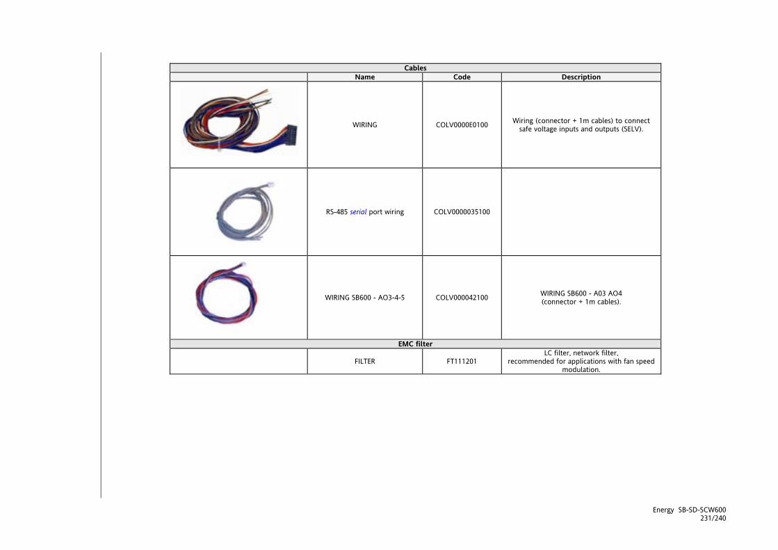
Energy SB-SD-SCW600 231/240
Cables
Name Code Description
WIRING COLV0000E0100 Wiring (connector + 1m cables) to connect safe voltage inputs and outputs (SELV).
RS-485 serial port wiring COLV0000035100
WIRING SB600 - AO3-4-5 COLV000042100 WIRING SB600 - A03 AO4 (connector + 1m cables).
EMC filter
FILTER FT111201 LC filter, network filter,
recommended for applications with fan speed modulation.

Energy SB-SD-SCW600 232/240
Temperature probes Name Code Description Documentation
SN691150 Probe NTC 103AT, 1.5m (plastic cap, 2-wire cable); Instruction sheet SN691150 GB-I
SN8T6H1502 NTC temperature probe 5X20 1.5m TPE IP68 Instruction sheet SN8T6H1502 GB-I
SN8T6A1502 NTC temperature probe 6X40 TPE STEEL IP68 Instruction sheet SN8T6A1502 GB-I
TEMPERATURE PROBES (1) (2)
SN8T6N1502 NTC temperature probe 6X50 TPE STEEL IP68 Instruction sheet SN8T6N1502 GB-I
Ratiometric transducers TD400030 Ratiometric transducer
EWPA 030 R 0/5V 0/30BAR Female connector
RATIOMETRIC TRANSDUCERS (1)
TD400050 Ratiometric transducer EWPA 050 R 0/5V 0/50BAR Female connector
Pressure transducers
TD200130 Pressure transducer
EWPA 030 4...20mA 0/30bar Male connector
TD200030 Pressure transducer
EWPA 030 4...20mA 0/30bar Female connector
TD200107 Pressure transducer
EWPA 007 4...20mA -5/8bar Male connector
PRESSURE TRANSDUCERS (1)
TD300008 Pressure transducer
EWPA 007 4...20mA -5/8bar Female connector
Instruction sheet 9IS41070
EWPA 007-030 GB-I-E-D-F-RUS
- - - Power EWPA 007-
30 GB-I-E-D-F
Pressure switches
Name Code Description
(1) HR range (automatic reset) - minimum 100,000 ON/OFF cycles available
(1)
HL range (manual reset) - minimum 6,000 ON/OFF cycles
PRESSURE SWITCHES (1)
(1) HC range (automatic reset) - minimum 250,000 ON/OFF cycles

Energy SB-SD-SCW600 233/240
Fan modules Name Code Description Documentation
CFS FAN MODULES (1) For item numbers
See instruction sheet
Single-phase speed regulators for currents from 2A to 9A
Instruction sheet 8FI40014
CFS -Fan Speed Modules GB-I-E-D-F
CF-REL FAN MODULE MW991300 6A 230V relay
Instruction sheet 8FI40014
CFS -Fan Speed Modules GB-I-E-D-F
CFS05 TANDEM FAN MODULE MW991012 5+5A 230V TRIAC
Instruction sheet 8FI40016
CFS05 - TANDEM - Fan Speed Module
GB-I-E-D-F
THREE-PHASE FAN REGULATOR (DRV 300) (1)
3 phases 12…20A/420V~ (IP22 or IP55)
LD312420T1S00 Specifications:
power supply 20A, 420V~; box: IP22.
Contact Eliwell Sales Department
LD320420T1S00 Specifications:
power supply 20A, 420V~; box: IP55.
Contact Eliwell Sales Department
LD312420T1G00 Specifications:
power supply 12A, 420V~; box: IP22.
Contact Eliwell Sales Department
LD320420T1G00 Specifications:
power supply 20A, 420V~; box: IP22.
Contact Eliwell Sales Department
<IMG INFO>
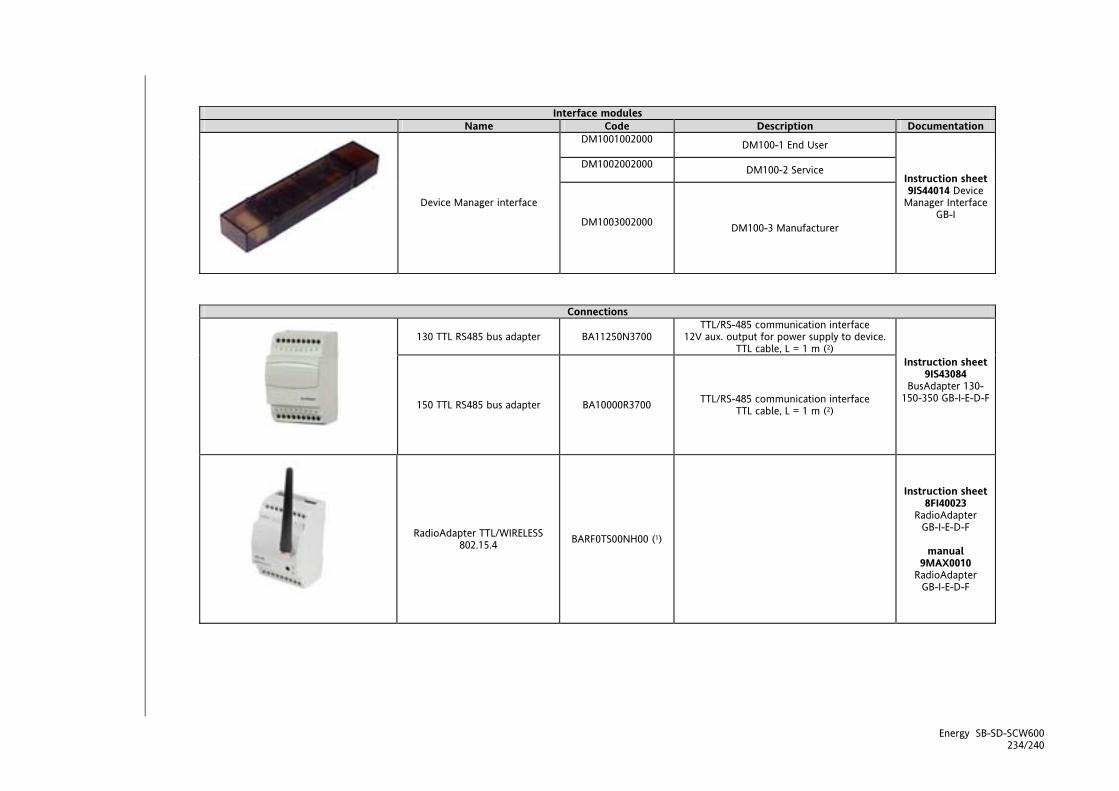
Energy SB-SD-SCW600 234/240
Interface modules Name Code Description Documentation
DM1001002000 DM100-1 End User
DM1002002000 DM100-2 Service
Device Manager interface
DM1003002000 DM100-3 Manufacturer
Instruction sheet 9IS44014 Device
Manager Interface GB-I
Connections
130 TTL RS485 bus adapter BA11250N3700 TTL/RS-485 communication interface
12V aux. output for power supply to device. TTL cable, L = 1 m (2)
150 TTL RS485 bus adapter BA10000R3700 TTL/RS-485 communication interface TTL cable, L = 1 m (2)
Instruction sheet 9IS43084
BusAdapter 130-150-350 GB-I-E-D-F
RadioAdapter TTL/WIRELESS 802.15.4 BARF0TS00NH00 (1)
Instruction sheet 8FI40023
RadioAdapter GB-I-E-D-F
manual
9MAX0010 RadioAdapter
GB-I-E-D-F
IMG INFO

Energy SB-SD-SCW600 235/240
Software Tools
Name Code Description Documentation
Device Manager Contact Eliwell Sales
Department
Manual 8MA00219
DeviceManager ITA 8MA00219
DeviceManager GB 8MA30219
DeviceManager SPA
8MA50219 DeviceManager
GER 8MA20219
DeviceManager FRE
8MAA0219 DeviceManager
RUS

Energy SB-SD-SCW600 236/240
Name Code Description Documentation
WebAdapter WA0ET00X700
WebAdapter Wi-Fi WA0WF00X700
Instruction sheet 9IS44065
WebAdapter GB-I-E-D-F-RUS
manual 8MA00202 WebAdapter ITA 8MA10202 WebAdapter GB 8MA20202 WebAdapter FRE 8MA30202 WebAdapter SPA 8MA50202 WebAdapter GER 8MAA0202 WebAdapter RUS
Demo Case
Name Code Description
Demo Case SB600/ST700 VAL00031K Demo case for SB600/ST700
(1) various item numbers available. Contact Eliwell Sales Department (2) Various lengths can be requested GENERAL NOTES: COLV cabling are not required if they are made by the manufacturer. Connection of remote keyboard via 3-way cables with no optional modules. Eliwell can also supply a variety of different NTC probes depending on the cable type (PVC or silicon) and length.
<IMG INFO> 99,45 101,3 0 2 18,7 -92 95
IMG INFO

Energy SB-SD-SCW600 237/240

Energy SB-SD-SCW600 238/240

Energy SB-SD-SCW600 239/240
33 ANALITIC INDEX
A Access to folders - menu structure............................. 16 Accessories ..................................................................... 229 ACS Heater for Anti-Legionnaire's Disease ............110 ADAPTIVE (FOLDER PAR/AD)...................................... 96 Adaptive function ..........................................................97 Adaptive function with hysteresis modification
....................................................................................... 98 Adaptive function with setpoint and hysteresis
modification................................................................ 98 Adaptive function with setpoint modification. 96 Adaptive parameters (Ad) - Adaptive .....................157 Alarm Display (AL).........................................................22 Alarm events (Par/EU folder) ......................................29 Alarm parameters (AL) - ALarm...............................164 Alarm table key..........................................................127 Alarms ............................................................................122 ALARMS AND DIAGNOSTICS (FOLDER PAR/AL) .. 122 Analogue alarms..........................................................126 Analogue inputs: Configuration table ......................32 Analogue inputs-Probes .............................................203 Analogue output TC1 - AO1 AO2 :
Configuration table ...............................................39 Analogue outputs ..........................................................38 ANNEXE A – MODELS AND ACCESSORIES ............. 227 Antifreeze operation with pump................................. 67 Antifreeze parameters with heat pump (AF) -
AntiFreeze ..................................................................157 ANTIFREEZE PARAMETERS WITH HEAT PUMP
(FOLDER PAR/AF) - ANTIFREEZE.......................... 100 Anti-Legionnaire's Disease......................................... 108 Automatic changeover ................................................. 50 Automatic reset .........................................................122 AUXILIARY OUTPUT (FOLDER PAR/HA).................... 85 Auxiliary output parameters (HA) - Auxiliary Output
.....................................................................................155 Availability of resources................................................59 B BLOCK HEAT PUMP (FOLDER PAR/HP)................... 111 Block heat pump 1 - setpoint....................................113 Block heat pump based on external
temperature ............................................................111 Block heat pump based on regulation
temperature ............................................................112 Block heat pump from digital input ........................113 BOILER (FOLDER PAR/BR) ............................................ 86 Boiler configuration....................................................... 86 Boiler differential............................................................87 Boiler parameters (br) -boiler ...................................155 Boiler regulation ............................................................88
C Change On/OFF state (folder St).........................198 Client Table ................................................................. 190 Compressor configuration ............................................55 Compressor on/off sequence .......................................59 Compressor Parameters (CP) - Compressor.... 150 Compressor timing .........................................................56 COMPRESSORS (FOLDER PAR/CP) .............................54 Configuration of analogue inputs ..............................32 Configuration of analogue outputs ...........................38 Configuration of device address................................226 Configuration of digital inputs....................................35 Configuration of digital outputs.................................37 Configuration of integration heaters ..................79 Configuration of internal circuit water pump .62 Configuration of parameter addresses................... 226 Configuration of SE600 expansion analogue inputs
........................................................................................32 Configuration of variable / state addresses .......... 226 Configuration parameters (CF) - Configuration .. 144 Configuration with Modbus RTU ..............................222 Configuring SKW remote terminal analogue inputs
........................................................................................32 Connecting the Multi Function Key ........................ 199 Continuous operation .....................................63; 68; 71 Control of the second pump ........................................63 Cross references.................................................................7 D Data format (RTU) ...................................................... 222 Defrost...............................................................................90 DEFROST (FOLDER PAR/DF).........................................89 Defrost parameters (dF) - deFrost ........................... 156 Defrosting cycle...............................................................91 Description of keys - combined action ................12 Description of keys and associated functions ....9 Device ‘On’ --> ‘Standby’ ..............................................11 Device ‘Standby’ --> ‘On’ ..............................................11 Device Manager interface component ................... 220 Device Manager software component ................... 220 DEVICEMANAGER.........................................................220 Differential temperature control ................................47 Differential temperature control in Cool / Heat
mode .............................................................................47 Digital alarms............................................................... 123 Digital inputs ...................................................................35 Digital inputs: Configuration table ......................35 Digital outputs ................................................................37 Digital temperature control.........................................48 Disclaimer.......................................................................219 Display ..............................................................................13 Display and LEDS ..........................................................217
Display and reset compressor/pump hours .............26 Display Inputs/Outputs (AiL, diL, tCL1/AOL, dOL)..18 Download from reset...................................................201 Dynamic ACS setpoint ................................................107 DYNAMIC SETPOINT (FOLDER PAR/DS) ................... 93 Dynamic setpoint parameters (dS) - dynamic
Setpoint......................................................................156 E Electric heater parameters (HI) - Electric Heaters 154 ELECTRICAL CONNECTIONS ...................................... 203 End defrost and coil drainage .....................................91 Entering a password (Par/PASS folder).....................28 Esempio collegamento SDW600/SCW600 – SE600
.....................................................................................210 ET(MT example.............................................................98 ET<MT example............................................................96 Example of AO1 / AO2 connection ..........................208 Example of AO3 - AO4 connection ..........................209 Example of AO5 connection..................................209 Example of automatic changeover based on
external air temperature..........................................50 Example of automatic changeover based on water
temperature ................................................................50 Example of connection of high voltage outputs...210 Example of connection SBW600 – SE600 ...............210 Example of connection SCW600 – SE600 – SKP10 –
SK22/22L ....................................................................212 Example of connection SCW600 – SKP 10..............211 Example of DO5 connection..................................210 Example of how to set the setpoint (SP)...................23 Example of low voltage input/output connection208 Examples of network connections............................ 210 EXP...................................................................................167 EXTERNAL CIRCUIT PUMP (FOLDER PAR/PE).......... 76 External circuit pump parameters (PE) - External
Pump ..........................................................................153 EXTERNAL EXCHANGER ELECTRIC HEATER
PARAMETERS (FOLDER PAR/HE) – ELECTRIC HEATERS ...................................................................... 83
External exchanger electric heater parameters (HE) - Electric Heaters.........................................................155
EXTERNAL EXCHANGER FAN (FOLDER PAR/FE) ..... 70 External exchanger fan analogue control in Cool .74 External exchanger fan analogue control in
Cool / Heat ................................................................72 External exchanger fan analogue control in Heat .74 External exchanger fan digital control in Cool / Heat
................................................................................71; 73 F Fan control in defrost.................................................... 75 Fan control with single condensation....................... 75 First switch on ................................................................. 15
Fixed modification (decalibration) of the setpoint (dS00=2).......................................................................95
Flow switch alarm ....................................................... 124 Folder visibility table................................................... 188 FUNCTIONS (FOLDER FNC)........................................196 Functions (Par/FnC folder) ...........................................28 G General Description ......................................................... 8 General specifications..................................................215 General warnings.......................................................203 H Heat pump block parameters (HP) - Heat Pump. 159 Heaters in defrost mode................................................82 HOW TO USE THIS MANUAL ......................................... 7 I I/O configuration parameters expanded on
expansion (CE) - Configuration Expansion ....... 138 I/O features ..................................................................216 Icons for emphasis............................................................7 Integration heater differential.....................................79 Integration heater regulation......................................81 Internal antifreeze heater ........................................77 Internal circuit antifreeze heater control..................78 INTERNAL CIRCUIT PUMP (FOLDER PAR/PI) ...........62 Internal circuit pump analogue control in Cool /
Heat........................................................................63; 65 Internal circuit pump digital control in Cool / Heat
.................................................................................63; 64 Internal circuit pump parameters (PI) - Internal
pump.......................................................................... 151 INTERNAL EXCHANGER ELECTRIC HEATERS (FOLDER
PAR/HI) .........................................................................77 INTRODUCTION................................................................ 8 K Keys ...................................................................................... 9 L LEDs and Display ............................................................13 LEDs: decimal point........................................................13 LEDs: States and Operating Modes ............................14 LEDs: utilities....................................................................15 LEDs: Values and Units of Measure ............................14 Local I/O configuration parameters (CL) -
Configuration Local................................................ 135 Low voltage (SELV) analogue output AO3-4-5:
Configuration table ................................................40 M Main Display Menu ........................................................16 Main functions: .................................................................8 Management of defrost alarms ..................................92 Managing resources ......................................................59 Manual alarm acknowledgment and reset..............12 Manual defrost................................................................92 Manual defrost activation (dEF folder) ...................197 Manual reset .............................................................. 122

Manual Reset (tA folder)............................................ 197 MECHANICAL ASSEMBLY........................................ 213 Mechanical dimensions........................................... 218 Mechanical specifications .......................................... 217 Minimum compressor on time....................................56 Minimum compressor on time for power stage
increase ........................................................................57 Minimum compressor switch on time for decrease in
power stages ...............................................................57 Minimum time ................................................................96 Minimum time between switching off/on for a given
compressor ..................................................................56 Minimum time between switching on/off in defrost
mode.............................................................................58 Minimum time between switching on/on for a given
compressor ..................................................................56 Minimum time between the switching off of more
than one compressor ................................................57 Minimum time between the switching on of more
than one compressor ................................................57 Modbus commands available and data areas .....223 Mode Change..................................................................52 Mode selection parameters (St) - Operating
modes ........................................................................149 Models ............................................................................ 227 Models and Features ........................................................8 Models SBW SDW SCW600 SE600 ...........................227 Modification (decalibration) of the setpoint as a
function of the dynamic setpoint input................ 93 Modification (decalibration) of the setpoint as
a function of the dynamic setpoint input with negative offset. ........................................................94
Modification (decalibration) of the setpoint as a function of the dynamic setpoint input with positive offset. .............................................................93
Modification (decalibration) of the setpoint based on the external temperature................................... 94
Modification (decalibration) of the setpoint based on the external temperature (dS00=1).................94
Modification (decalibration) of the setpoint based on the external temperature (dS00=1):Modification based on the external temperature with negative offset.....................94
Modification (decalibration) of the setpoint based on the external temperature (dS00=1):Modification based on the external temperature with positive offset ......................94
Modification based on the dynamic setpoint input with negative offset ...................................................94
Modification based on the dynamic setpoint input with positive offset.....................................................93
Modification of setpoint in heating.....................97 MT......................................................................................96
Multi Function key .......................................................199 Multi Function Key Component ............................... 220 N No. interventions ......................................................... 122 Non-power stage compressors (CP00 = 0) ...............54 O Operating Mode Menu..................................................17 Operating modes .................................................. 49; 114 OPERATING MODES – TEMPERATURE CONTROL
(FOLDER PAR/TR).......................................................42 Operating states .............................................................49 OPERATING STATES (FOLDER PAR/ST) .....................49 Operating states table...................................................51 Operation on call .............................................64; 68; 72 Operation on call: periodic pump activation...........65 Other timings ..................................................................58 P Parameters (folder PAr) ............................................27 PARAMETERS (PAR) .....................................................134 Parameters / visibility table ...................................... 167 Parameters / visibility table, folder visibility table
and client table ........................................................166 Permitted use.................................................................219 Post-ventilation...............................................................69 Power failure during defrost ........................................92 Power limitation - by external temperature (Cool
and Heat) ...................................................................115 Power limitation - by high pressure probe (Cool
and Heat) .................................................................117 Power limitation - by low pressure probe (Cool
and Heat) .................................................................118 Power limitation - by temperature (Cool and Heat)
......................................................................................116 POWER LIMITATION (FOLDER PAR/PL)...................114 Power limitation parameters (PL) - Power
Limitation ................................................................ 160 Power limitation to 50% ..............................................119 Power stage compressors (CP00 = 1,2) .....................55 Power supply - High voltage inputs (relay) ........... 203 Pressure probes ............................................................ 203 Probe errors table..................................................... 131 Programming menu.......................................................27 Proportional power step temperature control in
Cool/Heat mode .........................................................45 Proportional temperature control..............................45 Protection .........................................................................99 Pump antilock mode .....................................................66 R Real setpoint and hysteresis.........................................42 Real time ET .....................................................................96 RECIRCULATION FAN (FOLDER PAR/FI)....................68 Recirculation fan in Heating / Cooling .....................69 Recirculation fan parameters (FI) - Internal Fan . 152

References ...........................................................................7 Remote I/O configuration parameters (Cr) -
Configuration remote .............................................143 Remote terminals ......................................................228 Reset alarm log (folder EUr) ...................................... 202 Resource selection criterion .........................................60 Responsibility and Residual Risks ....................... 219 Reversal valve management........................................ 52 S SANITARY WATER AND ANTI-LEGIONNAIRE'S
DISEASE (FOLDER PAR/AS).................................... 102 Sanitary Water Antifreeze .......................................... 111 Sanitary water heater in Heat/Cool mode *..........105 Sanitary Water in HEAT mode ............................. 103 Sanitary Water Parameters (AS) ..............................157 Sanitary water regulation, AS mode ....................... 108 Sanitary Water, Cool mode ....................................... 105 SB600 General specifications.....................................215 SBW SDW636 models 2 TRIAC ..............................228 SBW SDW SCW 600 Analogue inputs .......................32 SE600 analogue inputs .................................................32 Secondary (external) exchanger fan parameters (FE)
- External Fan ...........................................................152 Selecting the circuit/evaporator.................................60 Selecting the compressor or power stage.................61 Serial ............................................................................... 217 Serial configurations - Protocol parameters ........... 40 Serial connections TTL connection ..........................203 Setpoint and hysteresis differentials Adaptive
function........................................................................43 Setpoint and hysteresis differentials Remote
differentials (from serial) .........................................43 Setpoint and hysteresis from parameter value .......42 Setpoint differential: dynamic differential ...............42 Setpoint differential: Economy differential.......43 Setpoint modification in cooling ..........................97 Setpoint regression ........................................................ 98 Setting the clock (CL) ....................................................19
SKP 10 32x74 terminal ..................................................41 SKP 10 Remote Terminal 32x74 ................................211 SKW Analogue inputs....................................................32 SKW22 - SKW22L remote LCD terminal ...........41; 212 Stand-by ...........................................................................11 Start defrost .....................................................................90 Start defrost setpoint .....................................................92 States Menu .....................................................................18 SUPERVISION.................................................................222 SYSTEM CONFIGURATION (FOLDER PAR/CF) ...32 T Table of Alarms............................................................ 127 TECHNICAL DATA.........................................................215 Technical data: ...............................................................8 Temperature control at INVERTER in Cool / Heat
mode .............................................................................46 Temperature control parameters (tr) -
temperature controller....................................... 148 Temperature control probes ........................................44 Temperature controller .................................................44 Temperature controller setpoint and hysteresis......42 Temperature probes.................................................... 203 Time Band Parameters (tE) ....................................... 160 TIME BANDS (FOLDER PAR/TE) ................................120 Transformer ...................................................................217 TRIAC.............................................................................. 203 TTL (COM 1) ................................................................. 203 Types of compressor.......................................................54 Typical applications:........................................................8 U Unintended Use............................................................ 219 USER INTERFACE (FOLDER PAR/UI) ............................. 9 User interface parameters (UI) - User Interface
..................................................................................... 145 W Wiring diagrams ........................................................203 Wiring Diagrams ......................................................... 204

E
Eliwell Controls S.r.l. Via dell’ Industria, 15 Zona Industriale Paludi 32010 Pieve d’ Alpago (BL) Italy Telephone +39 0437 986 111 Facsimile +39 0437 989 066
Sales: +39 0437 986 100 (Italy) +39 0437 986 200 (other countries) [email protected]
Technical helpline: +39 0437 986 300
E-mail [email protected]
www.eliwell.it
Energy SB-SD-SCW600 2009/12/
Cod: 8MA10222 © Eliwell Controls s.r.l. 2008-09 All rights
reserved.