energy management and control systems for hybrid wind
TRANSCRIPT
Energy Management and Control Systems for Hybrid Wind-Solar Energy
System with Battery Storage
By
Khandker Tawfique Ahmed
A Thesis Submitted to Saint Mary‘s University, Halifax, Nova Scotia
in Partial Fulfillment of the Requirements for
the Degree of Master of Science in Applied Science
June 30, 2016, Halifax, Nova Scotia
© Khandker Tawfique Ahmed, 2016
Approved: Dr. Adel Merabet
Supervisor
Division of Engineering
Approved: Dr. Hussein Ibrahim
Co-Supervisor
Wind Energy TechnoCentre
Gaspe, Quebec
Approved: Dr. Alain Joseph
External Examiner
Applied Energy Research Lab
N.S. Community College –
Waterfront Campus
Approved: Dr. David Swingler
Supervisory Committee Member
Division of Engineering
Date: June 30th, 2016
i
Energy Management and Control Systems for Hybrid Wind-Solar Energy
System with Battery Storage
By
Khandker Tawfique Ahmed
Abstract
A hybrid wind solar energy system with battery storage and its control systems are presented in
this dissertation. The proposed system consists of a wind turbine, a solar panel, a battery storage
unit and a set of loads. A power electronics interface, based on various converters, is used to
integrate the renewable energy sources and the storage device to the main DC-bus feeding a
single phase AC load. The main challenge of the hybrid system is to maintain the load demand
under constraints. The objective of the proposed controllers is to ensure a proper control and
coordination between all the sources of the system. At the wind energy side, a speed controller is
used to keep the rotor speed under control for safe operation of the wind turbine. At the solar
energy side, an incremental conductance method approach is realized to extract the maximum
power from solar irradiance. A bidirectional DC-DC converter is employed to control the
charging and discharging of the battery storage system. An energy management system is
developed to keep a balanced energy in the hybrid system. A load voltage regulator enables the
system to fix the output voltage and frequency. An experimental setup of the hybrid energy
system is developed using electrical devices from Festo (formerly LabVolt) and rapid control
prototyping is achieved using the real-time OPAL-RT digital control system. Experimental results
for various conditions are presented to validate the control algorithms developed in this work.
June 30th, 2016

ii
Acknowledgement
I would like to thank Saint Mary‘s University for providing me the opportunity to pursue the MSc
in Applied Science program with funding and research fellowship. I am thankful to TechnoCentre
for funding this research work. I would like to express my sincere gratitude to my supervisor Dr.
Adel Merabet for his valuable advice and help. I am thankful for the support provided by my co-
supervisor Dr. Hussein Ibrahim, from the TechnoCentre, Gaspe, Quebec.
I would like to thank my supervisory committee member Dr. David Swingler and the external
examiner Dr. Alain Joseph for their valuable comments and suggestions provided for my thesis.
Without their guidance and feedback, the thesis work could not have been a success. I would also
like to thank the entire research group of Laboratory of Control Systems and Mechatronics
(LCSM), Division of Engineering at Saint Mary‘s University for their support and help. And I
would also like to thank all the University officials who directly or indirectly helped me
throughout my program of study.
Finally, I would like to express my deepest gratitude to all of my family members and relatives.
June 30th, 2016
iii
Table of Contents
List of Figures ...................................................................................................................... vi
Nomenclature .................................................................................................................... viii
List of Abbreviations ........................................................................................................... xi
Chapter 1 ..............................................................................................................................1
Introduction ..........................................................................................................................1
1.1 Background ............................................................................................................................ 2
1.2 Literature Review................................................................................................................... 3
1.2.1 Hybrid operation ............................................................................................................. 4
1.2.2 Wind Energy Control ...................................................................................................... 7
1.2.3 Solar Energy Control ...................................................................................................... 8
1.2.4 Load Side Control ........................................................................................................... 9
1.2.5 Energy Storage System ................................................................................................. 11
1.3 Proposed System Diagram and Control Structure ............................................................... 13
1.4 Objectives, Scope and Contribution .................................................................................... 14
1.5 Outline of the Dissertation ................................................................................................... 15
Chapter 2 ............................................................................................................................ 17
Wind and Solar Energy Conversion Systems ...................................................................... 17
2.1 Introduction .......................................................................................................................... 17
2.2 Wind Energy Conversion System ........................................................................................ 17
2.2.1 Wind Turbine ................................................................................................................ 17
2.2.2 Permanent Magnet Synchronous Generator.................................................................. 19
2.2.3 Machine Side Converter Control .................................................................................. 20
2.3 Solar Energy Conversion System ........................................................................................ 22
2.3.1 Solar Cell ...................................................................................................................... 22
2.3.2 DC-DC Buck Converter ................................................................................................ 23
2.3.3 Maximum Power Point Tracking .................................................................................. 24

iv
2.4 Load Side Control ................................................................................................................ 25
2.5 Conclusion ........................................................................................................................... 27
Chapter 3 ............................................................................................................................ 28
Energy Management System............................................................................................... 28
3.1 Introduction .......................................................................................................................... 28
3.2 Battery Modeling ................................................................................................................. 28
3.3 Battery Types ....................................................................................................................... 30
3.4 Energy Storage System ........................................................................................................ 31
3.4.1 DC-DC Buck-Boost Converter ..................................................................................... 32
3.4.2 DC-Link Voltage Control ............................................................................................. 33
3.4.3 Energy Management System Algorithm ....................................................................... 34
3.5 Conclusion ........................................................................................................................... 35
Chapter 4 ............................................................................................................................ 36
Rapid Control Prototyping ................................................................................................. 36
4.1 Introduction .......................................................................................................................... 36
4.2 RT-Lab Overview ................................................................................................................ 37
4.3 Hardware & Software Details .............................................................................................. 38
4.3.1 OP5600 Real Time Simulator ....................................................................................... 38
4.3.2 OP8660 Controller and data Acquisition Interface ....................................................... 39
4.3.3 OPAL-RT‘s RT-LAB Software .................................................................................... 39
4.4 RT-Lab Modeling for Real Time Monitoring ...................................................................... 41
4.5 Conclusion ........................................................................................................................... 43
Chapter 5 ............................................................................................................................ 44
Experimentation & Results ................................................................................................. 44
5.1 Introduction .......................................................................................................................... 44
5.2 Experimental Setup .............................................................................................................. 44
5.3 Methodology ........................................................................................................................ 46
v
5.4 Limitations ........................................................................................................................... 47
5.5 Experimental Results ........................................................................................................... 47
5.5.1 System Performance under Variable Wind Power ........................................................ 48
5.5.2 System Performance under Variable Solar PV Power .................................................. 53
5.5.3 System Performance under Low Renewable Power ..................................................... 55
5.5.4 System Performance under Variable Load Power Demand .......................................... 58
5.6 Conclusion ........................................................................................................................... 60
Chapter 6 ............................................................................................................................ 61
Conclusion .......................................................................................................................... 61
6.1 Contribution ......................................................................................................................... 61
6.2 Recommendations for future work ...................................................................................... 62
Appendix ............................................................................................................................ 63
A. Specifications ........................................................................................................................ 63
B. Steps required for executing Simulink model in RT-Lab ..................................................... 65
References .......................................................................................................................... 69
vi
List of Figures
Figure 1 Proposed hybrid wind-solar energy system with battery storage .................................... 13
Figure 2 Proposed Control Structure ............................................................................................. 14
Figure 3 Generator side converter control scheme of the WECS .................................................. 21
Figure 4 Equivalent Circuit of a solar cell ..................................................................................... 22
Figure 5 Solar Energy Conversion System .................................................................................... 23
Figure 6 Flow chart of Incremental Conductance Method ............................................................ 25
Figure 7 Load side converter control for a single phase AC load .................................................. 27
Figure 8 Simple Electrical Model of a Battery .............................................................................. 29
Figure 9 Thevenin Electrical Model of a Battery .......................................................................... 29
Figure 10 Buck-Boost Converter ................................................................................................... 33
Figure 11 ESS and control structure .............................................................................................. 34
Figure 12 Energy management flowchart ...................................................................................... 35
Figure 13 Application categories of Real Time Simulation System .............................................. 37
Figure 14 Front view of OP5600 Real-Time Simulator ................................................................ 39
Figure 15 Real time system for the HIL hybrid energy with storage system................................. 41
Figure 16 Model Subsystems in RT-Lab ....................................................................................... 42
Figure 17 Experimental setup of the laboratory scale hybrid wind solar system with storage ...... 45
Figure 18 Hardware connections of the experimental set-up......................................................... 46
Figure 19 Wind turbine-generator speed ....................................................................................... 50
Figure 20 PV module current ......................................................................................................... 50
Figure 21 Power at different locations in the system (variable wind power) ................................ 51
Figure 22 DC-bus voltage .............................................................................................................. 52
Figure 23 Battery current ............................................................................................................... 52
vii
Figure 24 Load Voltage (zoom) ..................................................................................................... 52
Figure 25 Load Current (zoom) ..................................................................................................... 52
Figure 26 Load current................................................................................................................... 52
Figure 27 Frequency ...................................................................................................................... 52
Figure 28 Power at different locations in the system (variable solar power) ................................. 54
Figure 29 PV module current ......................................................................................................... 55
Figure 30 Battery current ............................................................................................................... 55
Figure 31 DC bus voltage .............................................................................................................. 55
Figure 32 Load voltage (zoom) ...................................................................................................... 55
Figure 33 Wind turbine-generator speed ....................................................................................... 57
Figure 34 PV module current ......................................................................................................... 57
Figure 35 Power at different locations in the system (low renewable power) ............................... 57
Figure 36 DC-bus voltage .............................................................................................................. 58
Figure 37 Battery current ............................................................................................................... 58
Figure 38 Power at different locations in the system (variable load power).................................. 59
Figure 39 DC bus voltage .............................................................................................................. 60
Figure 40 Battery current ............................................................................................................... 60
Figure 41 Function selection and settings in LVDAC-EMS window............................................ 67

viii
Nomenclature
Permanent Magnet Synchronous Generator
dL d-axis inductance
qL q-axis inductance
R Resistance of the stator windings
sdi Stator d-axis current
sqi Stator q-axis current
sdv Stator d-axis voltage
sqv Stator q-axis voltage
r Angular velocity of the rotor
v Rotor Flux
p Number of pole pairs
gT Electromagnetic torque
Wind Energy Conversion
mP Mechanical power produced by wind turbine
Air density

ix
wv Wind speed
pC Power coefficient
Tip-speed ratio
r Rotational speed of the rotor blade
r Radius of the turbine blade
rT Torque produced by wind turbine
Solar Energy Conversion
I Load current
PHI Photocurrent
RSI Diode reverse saturation current
SI Diode saturation current
K Boltzmann‘s Constant
N Diode ideality factor
T Temperature
V Terminal voltage
maxV Maximum Voltage
x
Load Voltage Control
rmsV RMS voltage
refV Reference voltage
Angle
v Instantaneous voltage
Angular velocity
Battery Modeling
rQ Remaining capacity
ratedQ Rated capacity
ocV Open-circuit voltage
sR Series Resistance
batI Battery current
batV Battery voltage
thV Equivalent Thevenin voltage
thR Equivalent Thevenin resistance
xi
List of Abbreviations
AC Alternating current
DC Direct Current
EMF Electromotive Force
ESS Energy Storage System
HRES Hybrid Renewable Energy System
HIL Hardware-in-Loop
IGBT Insulated Gate Bipolar Transistor
Li-ion Lithium-ion Battery
MGSet Motor-Generator Electric Drive
MPP Maximum Power Point
MPPT Maximum Power Point Tracking
Ni-Cd Nickel- Cadmium Battery
Ni-MH Nickel-metal hydride Battery
PD Proportional-Derivative
PI Proportional-Integral
PID Proportional-Integral-Derivative
xii
PMSG Permanent Magnet Synchronous Generator
P&O Perturb and Observe
PS Pure Simulation
PV Photovoltaic
PWM Pulse Width Modulation
RCP Rapid Control Prototyping
SOC State of Charge
VSC Voltage Source Converter
WECS Wind Energy Conversion System
XHP Extra High Performance

1
Chapter 1
Introduction
The demand for power is ever-increasing. Use of fossil fuels i.e. gas, coal, oil etc. in producing
power is also increasing. Still, there are over 1.5 billion people over the world deprived of access
of electricity living mostly in remote areas [1]. The source of electricity in those remote islands
and villages is diesel generator. This is both costly and hazardous for the environment due to the
global warming. Renewable energy resources like wind and solar energy are getting popularity
for these reasons.
Two or more renewable energy resources can be utilized in a hybrid renewable energy system
(HRES) which can work as a standalone or grid connected system. A hybrid renewable energy
system offers better quality in terms of reliability compared to single source based system. This is
due to the fact that one power source can supply power to the load when other sources are either
generating low or no power. The selection of renewable resources in HRES depends on the
particular location. In this research work a wind-solar HRES is considered. Wind and solar
combination is most promising source of generating energy primarily due to their complementary
nature advantage. Wind power generation could be low in time when solar power generation is in
its peak. On the other hand, the wind is often stronger in seasons when there is less solar
irradiance. Wind and solar energy are unpredictable in nature, as they depend on climate
condition. To improve the reliability of a wind-solar hybrid system other sources like battery
storage, fuel cell, diesel generator can also be integrated.

2
This research work focuses on the development of energy management system and control
systems for wind-solar hybrid energy system. The proposed control algorithms are tested to
validate the algorithms using RT-LAB real-time simulator. In this chapter, detailed backgrounds
of the system and literature review are discussed.
1.1 Background
In 2014, electric utilities and industry in Canada generated 639 terawatt hours [2].
Hydroelectricity accounts for 59.3 per cent of the country‘s electricity supply. Other sources
include coal, uranium, natural gas, petroleum and non-hydro renewable sources. Apart from
hydro resources, only 5.2% of the Canada‘s electricity supply comes from the renewable
resources. With its large landmass and diversified geography, Canada has substantial renewable
resources that can be used to produce energy. Moving water, wind, biomass, solar, geothermal,
and ocean energy are some of these resources. Wind and solar photovoltaic energy are the
fastest growing sources of electricity in Canada. About half of Canada‘s residential electricity
requirements could be met by installing solar panels on the roofs of residential buildings [3]. As
of December 31, 2014, Canada had over 5,130 wind turbines operating on 225 wind farms for a
total installed capacity of 9,694 megawatts and solar power reached 1,843 megawatts of
installed capacity [3].
There are approximately 292 off-grid remote communities in Canada where the power
generation depends on diesel generator [4]. As diesel contributes to carbon emission an
alternative solution is required to minimize its usage. Also, electricity demand in Canada is
expected to grow at an annual rate of 1 per cent between 2014 and 2040 [5]. Most of the growth
in energy demand would come from the industrial sector, where overall energy demand is
expected to grow at a rate of 0.7 per cent. In order to meet increasing demand, Canadian

3
producers need to increase their generation capacity. Hydroelectricity generation is expected to
continue to dominate the electricity supply mix but its share will decrease from 55 to 51 per
cent in 2040. In total generation, the share of wind power is projected to increase from over 7
per cent of total electricity generation in 2014 to close to 11 per cent by 2040, while the share of
biomass, solar and geothermal will account for about 5 per cent by 2040. A combination of
wind-solar energy will increase the efficiency of power generation. So hybrid energy system
based on wind and solar is gaining popularity among the researcher these days.
A non-profit organization named TechnoCentre éolien has developed an infrastructure of hybrid
renewable energy operation in Gaspe, Quebec to support the development of the wind industry.
The main purpose of this project is to study the potentialities and operation of hybrid energy
systems in Canada. Current infrastructure consists of a wind power plant, a photovoltaic (PV)
power plant, a diesel power plant, a compressed air storage unit, a motor-generator electric drive
(MGSet), a battery bench, a heat exchanger, a resistive load, secondary loads and a remote
monitoring system [6]. This research work is a part of that project.
1.2 Literature Review
Literature review on hybrid energy system is very extensive. A brief literature review is done in
this section. Since the study includes the operation of hybrid system consisting solar, wind and
battery, following topics are considered for literature review.
1. Hybrid operation
2. Wind Energy Control
3. Solar Energy Control

4
4. Load Side Control
5. Energy Storage System
1.2.1 Hybrid operation
HRES is a combination of two or more renewable energy resources with a storage or utility grid.
In this section, a combination of wind and solar, with an energy storage is considered for HRES
with a discussion from different authors about the configurations and control strategies used to
operate such systems. The HRES configuration proposed in [7] comprised of wind and solar
photovoltaic (PV) connected to grid. A multi input DC-DC converter is used to implement the
maximum power point tracking (MPPT). If one of the sources is unable to generate power, this
DC-DC converter can still transfer the maximum power from the other source. A full bridge
converter converts the DC power into the AC power. The control strategy is implemented using a
microcontroller.
A similar HRES approach is discussed in [8]. Here a single phase current hysteresis PWM control
strategy is proposed for the three-phase DC-AC inverter. Although hysteresis control provides a
fast dynamic response and good accuracy [9], it generates a variable switching frequency in the
converter [10],[11].
In [12], a DC and AC linked solar- wind based HRES is proposed. A dSPACE based controller is
used to implement both grid connected and standalone mode. In this HRES configuration, all the
sources are connected in parallel to the common DC bus through their individual DC-DC
converter. A MPPT algorithm is also applied. But the battery storage is uncontrolled as it is
directly connected to the DC bus.

5
The work in [13] presented a DC and AC bus linked HRES consisting of wind, solar and fuel cell.
In this configuration, the DC-DC converters of the PV and wind sources are incorporated with
voltage-based MPPT control technique to extract the maximum power from the sources. Fuel cell
is used as a storage device. This is also a grid connected system. The output voltage from each
source is controlled via a voltage controller. A single-phase current controlled inverter connecting
the DC and AC bus controls the current injected into the grid and also regulates the DC bus
voltage.
A similar DC and AC linked HRES approach is presented in [14]. In this configuration, a current
control voltage source inverter is connected to the utility grid. In this control strategy [15], the DC
bus voltage is controlled to ensure sufficient injection of the active power into the grid. This
controller generates reference active power for inverter control. Using rotating reference frame,
the components of the inverter output currents are generated. The inner current control loops
control the active and reactive power injected into the utility by independently controlling the
current components. However, this control approach is more suitable for three-phase load.
In [16], a HRES system comprised of wind, solar, battery and super-capacitor is presented. A
field orientation based speed control is realized by setting one current component reference to 0
and the other component current is used to control the rotational speed of the permanent magnet
synchronous generator (PMSG) according to the variation in the wind speed. The converter of the
storage unit is controlled using the current control strategy. A DC bus control strategy similar to
[15] is used to regulate the active and reactive power flow. The proposed system also works with
three-phase load.
In [17], a standalone microgrid model is presented by combining three renewable energy
resources. An active power and voltage control scheme is adopted in this standalone single three-
6
phase inverter control. This control strategy consists of two cascade loops to regulate the active
power injection and also maintain the magnitude of the AC bus. The inner current control loops
independently regulate the components of the inverter output current in the rotating reference
frame. The reference value of the inverter output current is obtained from the controlled active
power and voltage in the outer loop. The compensated outputs of the two current controllers are
used to generate the gate control signals of the inverter switches.
A fuzzy based PV control strategy for standalone three-phase voltage source inverter is proposed
in [18]. In this controller, fuzzy rules are used to set the parameters of a proportional-integral (PI)
controller to achieve a greater response.
The work in [19] presents three individual renewable energy resources with energy storage and a
grid interfacing inverter with virtual inductance at its output. The virtual inductance in the
proposed control strategy effectively decouples and can accurately control the real and reactive
power in both standalone and grid-connected mode. However, in virtual inductance, the
differentiation of line current can cause high frequency noise amplification, which in turn may
destabilize the voltage control scheme especially during transient events. To avoid noise
amplification a low pass filter is added [20],[21]. A high pass filter is added to avoid the
introduction of excessive noise [22]. However, this approach is the tradeoff between the overall
control scheme stability and the virtual inductor control accuracy.
HRES consists of different types of controllers. A speed controller is used to protect the wind
turbine. The maximum power from the solar PV is extracted by a maximum power point tracking
algorithm. To get the desired voltage at the output, a voltage controller is needed. Lastly an
energy management system is required to charge/discharge the storage according to the power
generation from the renewable sources.
7
There are significant differences between wind power and conventional power generation system.
Wind turbines often utilize different converter based generating systems. Wind is the prime
mover of the wind turbines, which is not controllable and fluctuates randomly. Besides, the
typical capacity of individual wind turbines is much smaller compared to the conventional utility
generators. Due to these differences, wind generation interacts differently with the network and
wind generation may have both local and system-wide impacts on the operation of the power
system. The wind energy configuration in TechnoCentre éolien is developed with a permanent
magnet synchronous generator (PMSG) based wind energy conversion system with two-level
voltage source converter (VSC). A typical configuration, where PMSG is directly coupled with
the wind turbine, is used in this study [23]. Two back to back IGBT converters are used to
convert AC signal to DC and then back to AC at the load side [24].
1.2.2 Wind Energy Control
A major concern of wind energy conversion system (WECS) is to control the speed of the wind
turbine. A control system is required to operate the wind turbine at rated wind speed maintaining
a desired voltage level. Speed control of wind turbine is also important to ensure the safety of the
WECS, converters, transformers and loads. A rotor speed estimation based non-linear speed
controller is presented in [25]. The proposed control system has two parts, a machine side
converter control and a grid side converter control. Machine side converter control is used to run
the wind turbine in maximum power point (MPP) for maximum power generation.
Another approach uses a proportional-integral-derivative (PID) based pitch regulation to control
the speed [26]. A transfer function of wind turbine is derived to apply the PID controller. This
PID controller is designed considering the non-linearity and the step response of the wind turbine.

8
In [27], a control scheme for an interior permanent magnet synchronous generator based variable
speed wind turbine with battery storage is discussed. The speed control of the wind turbine is
achieved by controlling the two components of the stator current.
Adaptive sliding mode controller is another method to solve this problem [28]. This adaptation
strategy consists of updating the sliding gain and the turbine torque, which is considered
unknown by the controller. The adaptation algorithms for the sliding gain and the torque
estimation are carried out using the sliding surface to overcome the drawbacks of the
conventional sliding mode control.
1.2.3 Solar Energy Control
Since the dawn of the civilization human being have been harnessing solar energy, radiant light
and heat from the sun, using a range of ever-evolving technologies. Since the scaling of the input
power source is easy, solar PV systems are an excellent choice in remote areas for low and
medium level power generation. The building block of PV array is a solar cell, which is basically
a p-n semiconductor junction that directly converts the solar irradiation into a DC current using
the photovoltaic effect. Maximum power point tracking (MPPT) is an integral part of solar PV
systems. MPPT is a technique that ensures the maximum power extraction from non-linear
energy resources like solar photovoltaic, wind energy systems and tidal energy etc. For solar PV
systems, MPPT algorithm allows the controller to follow the optimum voltage and current from a
photovoltaic module. Perturb & Observe (P&O) is the most widely used among the existing
MPPT techniques. In this method, the operating voltage of PV array is perturbed by small
increment and the corresponding change in power due to that is used to calculate the maximum
power point (MPP) [29],[30]. At the MPP, the derivative of the power with respect to the voltage
should be zero. If the derivative is greater than zero, the operating point is on the left of MPP. If
9
the derivative is less than zero, the operating point is on the right of MPP. This method is the
most popular because of its simplicity, low cost, ease of implementation and its operation doesn‘t
rely on the knowledge of PV characteristics [31]-[34]. One of the biggest drawbacks of this
algorithm is that it has a poor performance under rapid changing irradiation [35],[36].
Another technique is incremental conductance method, which is based on comparing the changes
in voltage and current. This algorithm calculates the incremental changes in current and voltage
[37]. The incremental conductance algorithm is derived by differentiating the PV array power
with respect to voltage and setting the result equal to zero. As the control decision is based on
two distinct variables, incremental conductance method has good robustness to measurement
noise compared to the P&O method [38].
Another MPPT method named constant voltage MPPT algorithm relies on the current-voltage (I-
V) curve of the PV array. In the simplest from, the open circuit voltage has a linear relation with
MPP. The constant of proportionality is selected between 0.78 and 0.92 [29]. As this is an
estimation technique based on PV cells under uniform condition, it is unable to accurately find
MPP location under non-uniform conditions.
A variety of artificial intelligence based MPPT techniques have been proposed in different
papers. A fuzzy logic based MPPT is proposed in [39],[40]. Artificial Neural Network provides a
mechanism to predict the MPP based on PV systems experience in environmental conditions [41].
1.2.4 Load Side Control
Most of the appliances in North America operate in 120V voltage and 60Hz frequency. So there
is requirement to control the output voltage and frequency of HRES. There exist many methods to
control the frequency and the voltage. In [42], an IGBT based voltage and frequency controller

10
with a battery at its DC link for an asynchronous generator is proposed at the load side. This
controller has bidirectional active and reactive power flow capability by which it can control the
system voltage and frequency. The control scheme is based on the generation of reference source
current. The active component of reference source current is used to control the magnitude of
generated voltage and the reactive component of reference source current is used to regulate the
frequency of the generated voltage. A PI controller is used to accomplish these tasks.
Different topologies for single phase inverter are discussed in [43]. Control of both single stage
and multi-stage inverter are discussed in the paper. A direct-quadrature (d-q) rotating frame
control method for single phase full bridge inverter in a hybrid energy system is presented in [44].
To achieve this d-q transformation, an imaginary orthogonal circuit was created by differentiating
the state variables from the original inverter circuit in order to emulate the q-axis dynamics. The
proposed controller attains infinite loop gain in the rotating coordinate, thus providing zero
steady-state error at the fundamental frequency of the converter.
In [45], the inverter is controlled with a fast inner current loop with a slower outer voltage loop
which eliminates the weakly damped inductive-capacitive LC filter of the inverter. While this
method results in improved performance of the inverter under linear loads, it deteriorates under
nonlinear loads.
In [46], a common inner AC current loop has been presented. In [47], the inverter controls the
active power flow from the renewable energy source to the grid and also performs the nonlinear
load current harmonic compensation by keeping the grid current almost sinusoidal. The control
scheme employs a current reference generator based on sinusoidal signal integrator and
instantaneous reactive power (IRP) theory together with a dedicated repetitive current controller.
Another approach based on repetitive controller gained attention nowadays [48]. However, they
11
require quite complex compensation or a continuous knowledge of the load. They are also known
to be slow and only effective for disturbances that are of the harmonics of the fundamental.
1.2.5 Energy Storage System
Energy storage system (ESS) is the heart of HRES. The purpose of an energy storage system is to
regulate energy balance between the sources and the load of HRES. Several methods have been
proposed by different authors for ESS.
A dual mode hybrid wind-solar energy system is proposed in [12]. It proposes an energy
management program that communicates the value of power references to wind and solar sources.
System variables such as voltages and currents are used to make decision by the supervisory
system. The main purpose of the supervisory control is to keep the battery charged by keeping the
DC-Link voltage at nominal level. One problem with this approach is that battery cannot
discharge when the power generations from the sources are reduced.
An energy management system for PMSG based standalone wind energy system is discussed in
[49]. The energy storage system consists of battery and super-capacitor both connected to the
DC-bus. The energy management algorithm depends on the power generation from wind and
load power. If there is an excess power, battery is charged and vice versa. It didn‘t consider a
hybrid system. Also it is a simulation based work.
Authors in [50] have proposed a method to improve the battery life in a small-scale wind energy
system using super-capacitor. Different control strategies for battery/super-capacitor are
presented in [51]. It discussed how these control can be used in hybrid energy storage system.
Application of super-capacitor in grid connected Doubly Fed Induction Generator (DFIG) system
is demonstrated in [52].

12
In [53], a DC-link voltage based energy management scheme is proposed for a PV-based hybrid
energy system. The main purpose of the energy management system is to reduce the stress on the
battery. A lab-scale grid connected PV generation system with battery storage is proposed in [54].
The energy management system is responsible for charging the battery from the utility grid or PV
and discharge to supply power to the local load and the utility grid. A simulation based wind-
diesel system with battery storage is proposed in [55]. The energy management system is used to
send a command to the dumping load and to the battery to regulate the system frequency.
However, management and control coordination of a hybrid energy system consisting of a
PMSG, solar PV and energy storage have received a very little research attention.
13
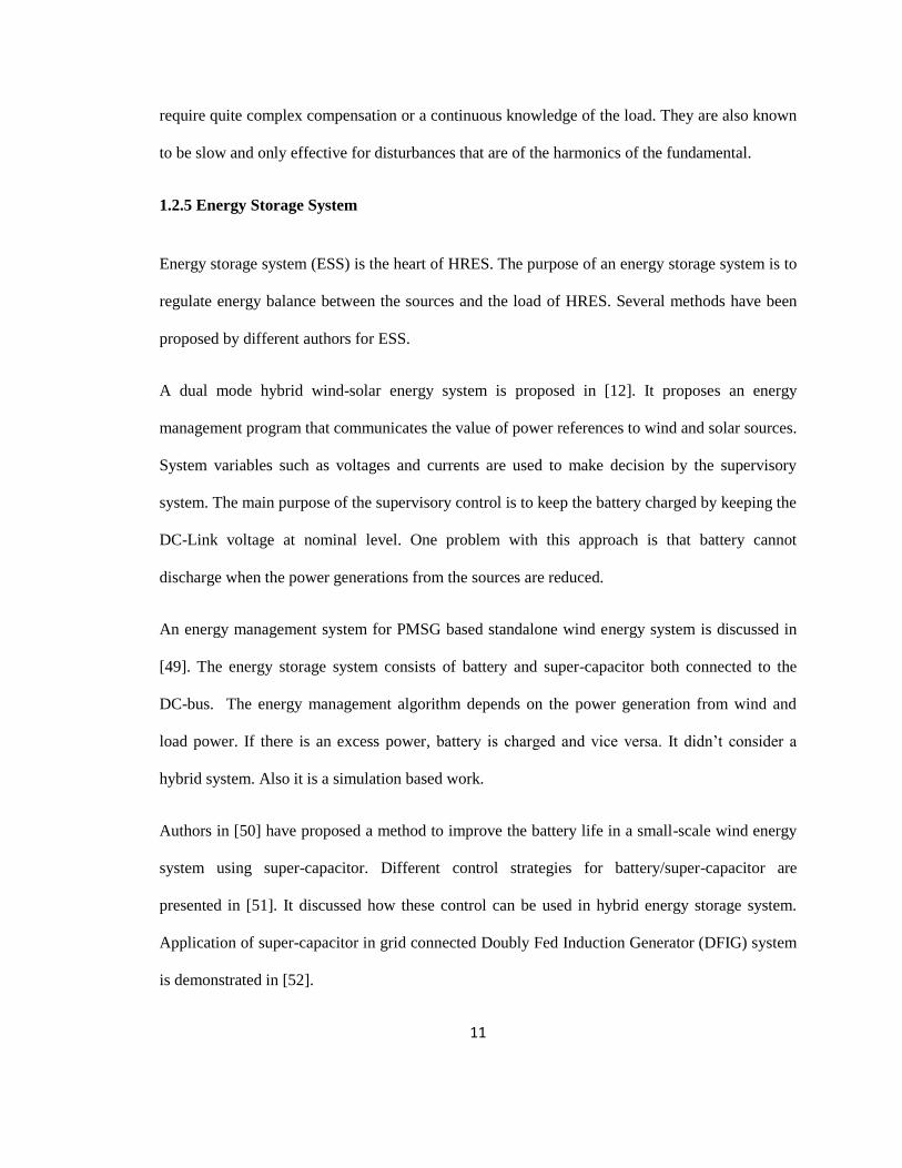
1.3 Proposed System Diagram and Control Structure
The main purpose of this research work is to develop an experimental model of hybrid wind solar
energy system with battery storage. The main components of this system are wind turbine, solar
panel, battery, converters, inverters, filter and resistive loads. A diagram of the proposed hybrid
system is depicted in Fig.1.
Figure 1 Proposed hybrid wind-solar energy system with battery storage
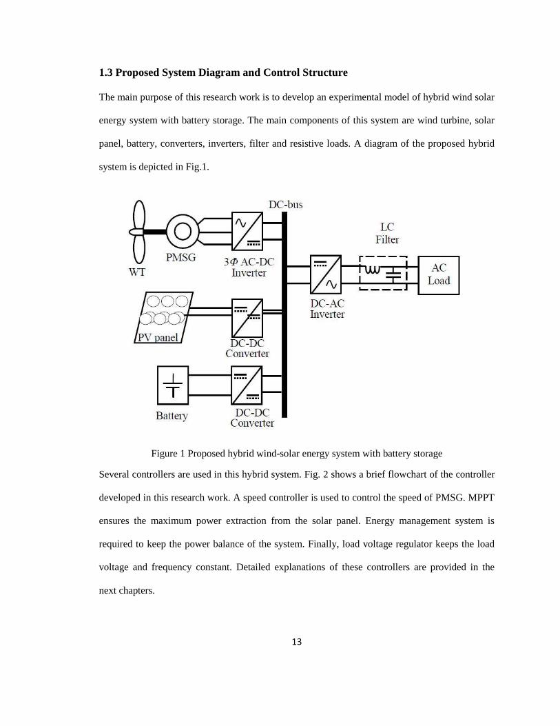
Several controllers are used in this hybrid system. Fig. 2 shows a brief flowchart of the controller
developed in this research work. A speed controller is used to control the speed of PMSG. MPPT
ensures the maximum power extraction from the solar panel. Energy management system is
required to keep the power balance of the system. Finally, load voltage regulator keeps the load
voltage and frequency constant. Detailed explanations of these controllers are provided in the
next chapters.
14
Figure 2 Proposed Control Structure
1.4 Objectives, Scope and Contribution
1) To implement an experimental laboratory model for wind energy conversion system (WECS),
solar energy conversion system and apply a maximum power point tracking algorithm to extract
the maximum power.
2) To develop an experimental laboratory model for stand-alone wind-solar hybrid energy
system.

15
3) To develop a battery charging-discharging system to use the battery as a back-up power in this
hybrid system.
4) To develop an energy management system to share the power generated by the hybrid system,
to increase the system reliability.
Contribution – A part of the research infrastructure at TechnoCentre éolien focuses on
integrating the wind turbine system with Solar PV generation unit and control the power
generation of both to supply test loads. For this, TechnoCentre éolien requires to develop control
systems for HRES. The thesis project is envisaged to provide knowledge on technical feasibility
of control systems development for optimization of power generated from HRES. The main
contribution of the research is presented in chapters 2, 3 and 5.
1.5 Outline of the Dissertation
Chapter 2:
In this chapter, the wind energy conversion system (WECS) and the solar energy conversion
system are studied through a background with fundamental components and control strategies for
both systems.
Chapter 3:
An energy management system is analyzed to operate the energy storage (battery) and the DC-
DC converter through adequate control schemes.
Chapter 4:
Real time simulation environment and rapid control prototyping (RCP) are used to build the
hybrid renewable energy system. Starting with a brief overview, this chapter discusses the

16
hardware details, real-time simulation environment and RT-LAB modeling. Also includes
discussion on how to execute model under RT-LAB.
Chapter 5:
Experimental setup to emulate the hybrid wind-solar energy conversion system with battery
storage and experimental results are presented and discussed in this chapter.
Chapter 6:
This chapter concludes the thesis with the suggestions of some future work.
17
Chapter 2
Wind and Solar Energy Conversion Systems
2.1 Introduction
Due to the ever increasing demand in commercial, industrial, agricultural and domestic
sectors, fossil fuel resources are becoming scarce. For this reason, alternative energy resources
like wind, solar, hydro, tidal and geothermal etc. are being utilized largely to generate power in
recent years. A renewable energy based hybrid system offers a better option than a single source
based system in terms of cost, reliability and efficiency. Wind-solar is a promising combination
due to their complementary nature advantage [56].
This chapter demonstrates the fundamental components and control strategies of wind energy
conversion system (WECS) and solar energy conversion system. Mathematical equations for the
wind turbine, the permanent magnet synchronous generator and the solar cell are briefly
discussed. In WECS, a machine side controller is applied to control the speed. In solar system, to
ensure the maximum power extraction, a maximum power point tracking algorithm is applied.
Finally, the load side converter control of the hybrid system, to regulate the load voltage and
frequency, is discussed and detailed in this chapter.
2.2 Wind Energy Conversion System
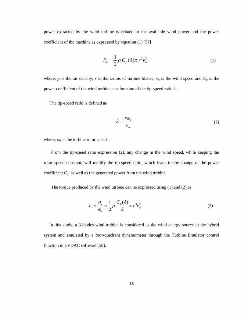
2.2.1 Wind Turbine
The wind turbine is the heart of the wind energy conversion system (WECS). Wind rotates the
blades of the wind turbine, which drives electrical generator to produce electrical power. The
18
power extracted by the wind turbine is related to the available wind power and the power
coefficient of the machine as expressed by equation (1) [57]
32)(
2
1wpm vrCP (1)
where, ρ is the air density, r is the radius of turbine blades, vw is the wind speed and Cp is the
power coefficient of the wind turbine as a function of the tip-speed ratio λ .
The tip-speed ratio is defined as
w
r
v
r (2)
where, ωr is the turbine rotor speed.
From the tip-speed ratio expression (2), any change in the wind speed, while keeping the
rotor speed constant, will modify the tip-speed ratio, which leads to the change of the power
coefficient Cp, as well as the generated power from the wind turbine.
The torque produced by the wind turbine can be expressed using (1) and (2) as
23)(
2
1w
p
r
mr vr
CPT
(3)
In this study, a 3-blades wind turbine is considered as the wind energy source in the hybrid
system and emulated by a four-quadrant dynamometer through the Turbine Emulator control
function in LVDAC software [58].
19
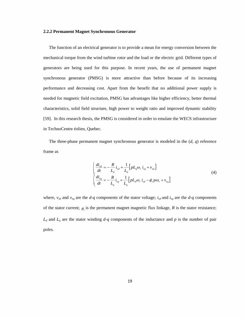
2.2.2 Permanent Magnet Synchronous Generator
The function of an electrical generator is to provide a mean for energy conversion between the
mechanical torque from the wind turbine rotor and the load or the electric grid. Different types of
generators are being used for this purpose. In recent years, the use of permanent magnet
synchronous generator (PMSG) is more attractive than before because of its increasing
performance and decreasing cost. Apart from the benefit that no additional power supply is
needed for magnetic field excitation, PMSG has advantages like higher efficiency, better thermal
characteristics, solid field structure, high power to weight ratio and improved dynamic stability
[59]. In this research thesis, the PMSG is considered in order to emulate the WECS infrastructure
in TechnoCentre éolien, Quebec.
The three-phase permanent magnet synchronous generator is modeled in the (d, q) reference
frame as
sqrvsdrd
q
sq
q
sq
sdsqrq
d
sd
d
sd
vpipLL
iL
R
dt
di
vipLL
iL
R
dt
di
1
1
(4)
where, vsd and vsq are the d-q components of the stator voltage; isd and isq are the d-q components
of the stator current; v is the permanent magnet magnetic flux linkage, R is the stator resistance;
Ld and Lq are the stator winding d-q components of the inductance and p is the number of pair
poles.

20
2.2.3 Machine Side Converter Control
The size of the experimental wind turbine is small and the external stiffness is neglected
compared to the other quantities. Therfore, its drive train can be represented as a single lumped
mass with the following model
grrr TKT
Jdt
d
1 (5)
where, ωr is the rotor angular speed, J is the total moment of inertia and K is total damping and Tg
is the generator electromagnetic torque.
The model (5), as an approximation of the rotor dynamics, has been considered suitable for
control purpose and been used in several works [60],[61].
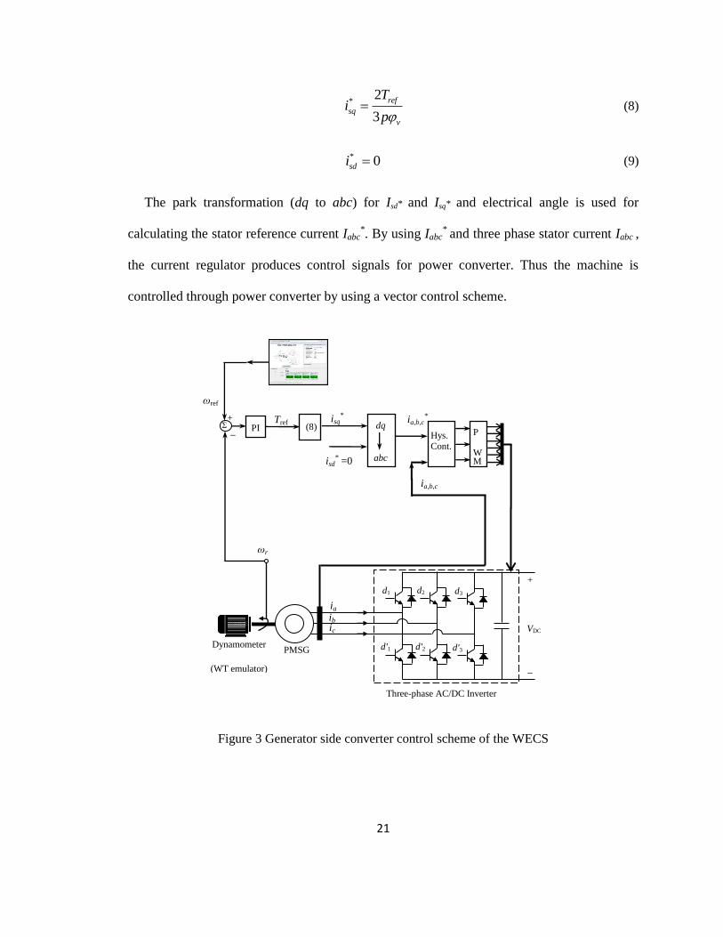
A flux weakening vector control scheme is used for controlling the PMSG as shown in
Fig. 3 [62]. The complete PMSG drive system consists of: three-phase power converter,
generator and machine side speed and current controllers. The vector controller generates
PWM signals through a three-phase current regulator. An optimal control is employed to
regulate the line current amplitude corresponding to desired torque reference Tref;
consequently the nominal value of flux is maintained. A proportional-integral (PI) controller
based speed control is used for obtaining the torque reference. The equations used to develop
the control system are given below. Equation (6) and (7) are used in modeling simple PI-
controller for speed control, equation (8) and (9) are used for modeling the inputs for the
current regulator, which is a simple hysteresis controller [63].
error ref r (6)
( ) ( ( ))ref ptorque error itorque errorT K K t dt (7)
21
*2
3
ref
sq
v
Ti
p (8)
* 0sdi (9)
The park transformation (dq to abc) for Isd* and Isq* and electrical angle is used for
calculating the stator reference current Iabc*. By using Iabc
* and three phase stator current Iabc ,
the current regulator produces control signals for power converter. Thus the machine is
controlled through power converter by using a vector control scheme.
Figure 3 Generator side converter control scheme of the WECS
Dynamometer
(WT emulator)
ωref
ωr
ia,b,c
isq*
isd* =0
ia,b,c* +
_
Σ PI Hys. Cont.
(8) Tref
d3 d2
d'2 d'3
Three-phase AC/DC Inverter
ia
d1
d'1
VDC
ib ic
PMSG
+
_
P
WM abc
dq
22
2.3 Solar Energy Conversion System
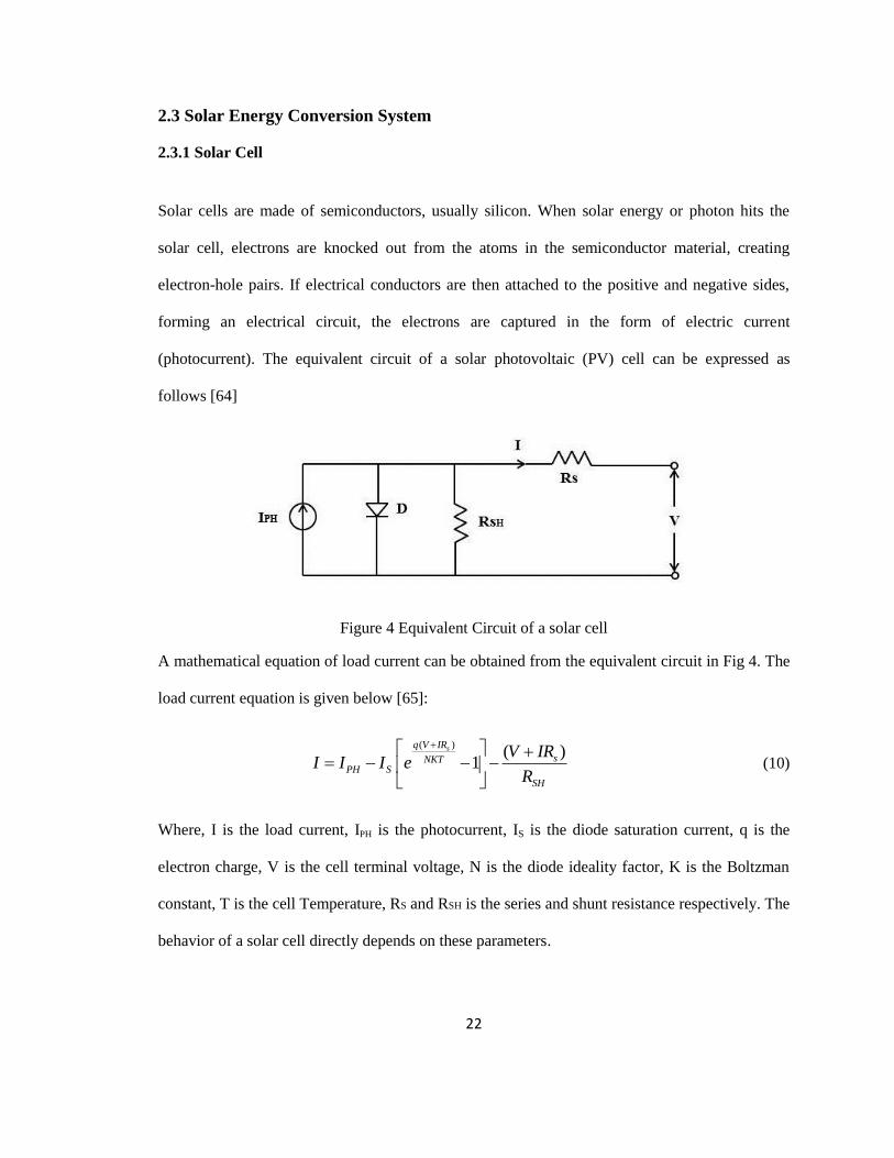
2.3.1 Solar Cell
Solar cells are made of semiconductors, usually silicon. When solar energy or photon hits the
solar cell, electrons are knocked out from the atoms in the semiconductor material, creating
electron-hole pairs. If electrical conductors are then attached to the positive and negative sides,
forming an electrical circuit, the electrons are captured in the form of electric current
(photocurrent). The equivalent circuit of a solar photovoltaic (PV) cell can be expressed as
follows [64]
Figure 4 Equivalent Circuit of a solar cell
A mathematical equation of load current can be obtained from the equivalent circuit in Fig 4. The
load current equation is given below [65]:
( )( )
1sq V IR
sNKTPH S
SH
V IRI I I e
R
(10)
Where, I is the load current, IPH is the photocurrent, IS is the diode saturation current, q is the
electron charge, V is the cell terminal voltage, N is the diode ideality factor, K is the Boltzman
constant, T is the cell Temperature, RS and RSH is the series and shunt resistance respectively. The
behavior of a solar cell directly depends on these parameters.

23
2.3.2 DC-DC Buck Converter
A DC/DC buck converter regulates the voltage to operate the solar energy conversion system at
maximum power point. The basic configuration is shown in Fig. 5.
Figure 5 Solar Energy Conversion System
When S1 is turned on, current begins flowing from the input source through S1 and inductor, and
then into capacitor and the load. The magnetic field in inductor therefore builds up, storing
energy in the inductor. When S1 is turned off, the inductor opposes any drop in current by
suddenly reversing its EMF, and now supplies current to the load itself via flywheel diode. The
DC output voltage which appears across the load is a fraction of the input voltage according to
equation
out inV V D (11)
Where, D is the duty cycle. So varying the duty cycle the buck converter‘s output voltage can be
varied. MPPT controller generates the duty cycle to operate the buck converter.
V PV
PWM MPPT
_
+
VDC
I
S1
DC-DC Buck Converter

24
2.3.3 Maximum Power Point Tracking
The MPPT controller ensures maximum power from the non-linear PV source. MPPT allows
the PV module to operate at optimum voltage and current. Hence, the extraction of maximum
power is ensured. There are several methods for MPPT and the most common are [66]
1. Perturb & Observe (P&O) method
2. Constant Voltage method
3. Incremental Conductance method
Among these methods, incremental conductance method is recommended due to the fact that it
offers good yield under rapidly changing atmospheric conditions. Incremental conductance
method measures the incremental change in the voltage and the current to predict the effect of a
voltage change. It estimates the relation between the operating point voltage, V, and the
maximum power point voltage, Vmax [66]. When light intensity and temperature changes, the
incremental conductance method control the output voltage smoothly and also reduces oscillation
phenomena near the maximum power point [67].
The method can be expressed following the three conditions:
;( 0)dI I dp
dV V dV at MPP thus V=Vmax (12.a)
;( 0)dI I dp
dV V dV left of MPP thus V<Vmax (12.b)
;( 0)dI I dp
dV V dV right of MPP thus V>Vmax (12.c)
The flowchart of this algorithm is shown in Fig. 6.

25
Figure 6 Flow chart of Incremental Conductance Method
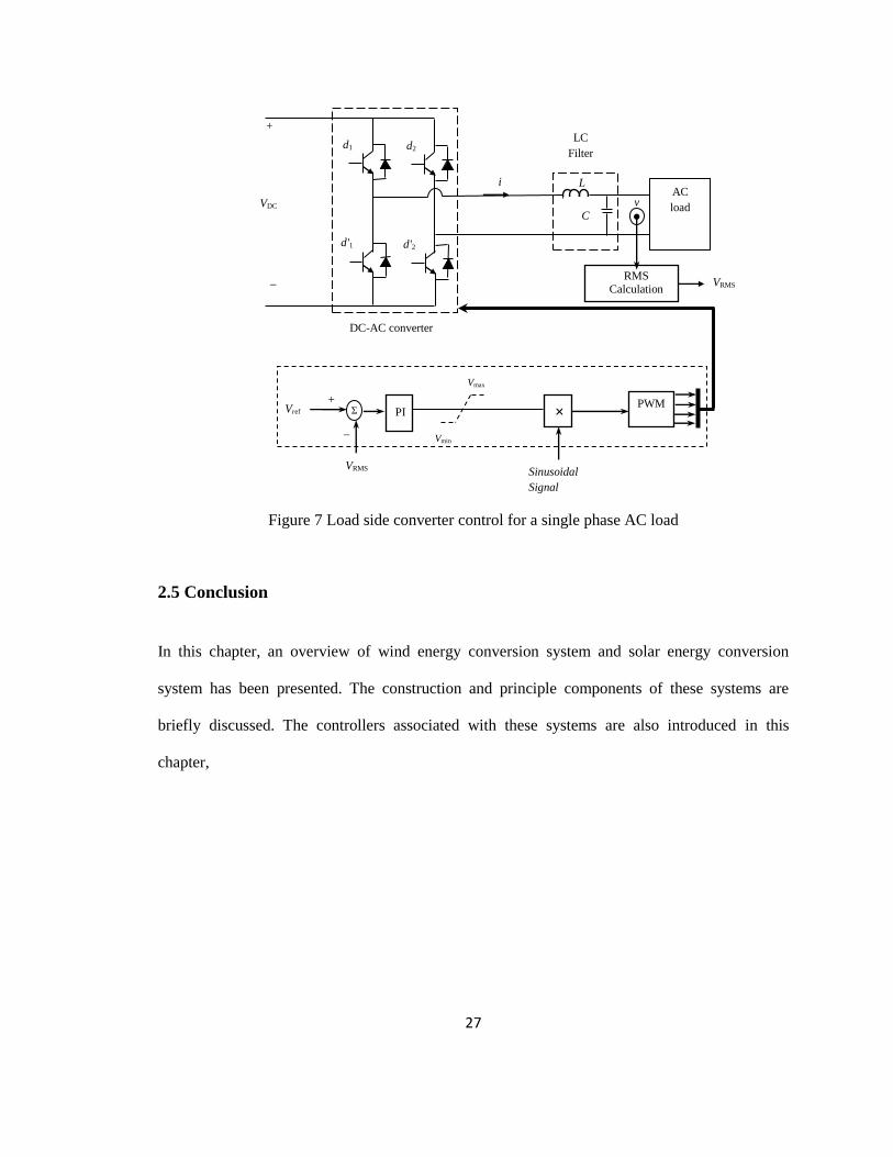
2.4 Load Side Control
The single phase load is connected to the hybrid energy conversion system through a single
phase DC-AC inverter, as shown in Fig. 7, which is controlled to regulate the load side voltage
and the frequency. An inductive-capacitive (LC) filter is used to remove the higher order
harmonics from the output AC voltage.
The instantaneous output voltage is converted to DC RMS voltage. If the instantaneous value of
1( ) 2 sin( )rmsv t V t and 2( ) 2 cos( )rmsv t V t are known, RMS value can be
calculated using the below trigonometric function, shown in equation (13) [68]

26
2 2 2{ 2 sin( )} { 2 cos( )} ( 2 )rms rms rmsV t V t V (13)
When the inverter output voltage 1( ) 2 sin( )rmsv t V t is sensed via the data acquisition,
then the voltage 2( ) 2 cos( )rmsv t V t can be calculated by differentiating 1( )v t and
dividing by ω. This computation is done using Simulink. Therefore the RMS value is obtained by
the following equation
2 21 1 ( ){ ( ) ( . ) }
2rms
dv tV v t
dt (14)
The calculated Vrms is compared with reference voltage Vref and the error signal is passed to a
PI controller. The output of the PI controller is multiplied with a modulating sinusoidal wave.
Finally this signal is used to generate PWM for inverter. As far as the frequency of the output AC
voltage is concerned, it can be maintained at specified value by choosing the frequency of
sinusoidal reference signal while generating the PWM pulses.
27
Figure 7 Load side converter control for a single phase AC load
2.5 Conclusion
In this chapter, an overview of wind energy conversion system and solar energy conversion
system has been presented. The construction and principle components of these systems are
briefly discussed. The controllers associated with these systems are also introduced in this
chapter,
+
_
Σ PI Vref PWM
VRMS
RMS Calculation
Vmax
Vmin
_
+
VDC AC
load
d2 d1
d'1 d'2
L
LC
Filter
DC-AC converter
i
v
C
VRMS
×
Sinusoidal
Signal

28
Chapter 3
Energy Management System
3.1 Introduction
Distributed power generation systems based on renewable resources like wind, solar etc. are
gaining popularity these days. An energy management system is necessary to keep the energy
balance of this hybrid system.
In this chapter, the essential components of an energy storage system and its control schemes are
briefly discussed. Battery modeling, battery types and an algorithm for energy management
system is also detailed in this chapter.
3.2 Battery Modeling
The battery has the characteristics of high energy density and relatively low power density. The
internal resistance is the major factor for the limited charging and discharging current capability
[69]. The internal equivalent series resistance has different values under charging and discharging
operating conditions. The charging and discharging efficiency are nonlinear functions of current
and state of charge (SOC). The SOC is defined as the percentage of the remaining capacity of a
battery. SOC can be expressed as equation (15)
( ) 100%r
rated
QSOC
Q (15)
Where, Qr and Qrated are remaining capacity and rated capacity of the battery respectively, both in
Ampere-Hour (Ah).

29
A simple battery model contains two parts, a controlled voltage source or open circuit voltage Voc
and a variable series resistor Rs as shown in fig. 8 [70].
Figure 8 Simple Electrical Model of a Battery
The current flowing into the battery from cathode is regarded as the positive direction. The
electrical behavior of this model can be expressed as equation (16)
bat oc bat sV V I R (16)
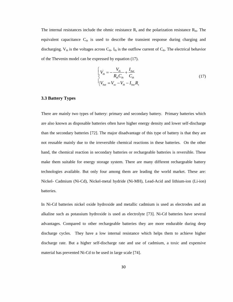
This simple model doesn‘t consider the dynamic response of a battery. A more accurate Thevenin
model connects a parallel RC network in series based on the simple model, describing the
dynamic characteristics of the battery [71]. As shown in Figure 9, it is mainly composed of three
parts including open-circuit voltage Voc, internal resistances and equivalent capacitance.
Figure 9 Thevenin Electrical Model of a Battery
30
The internal resistances include the ohmic resistance Rs and the polarization resistance Rth. The
equivalent capacitance Cth is used to describe the transient response during charging and
discharging. Vth is the voltages across Cth. Ith is the outflow current of Cth. The electrical behavior
of the Thevenin model can be expressed by equation (17).
.th bat
th
th th th
bat oc th bat s
V IV
R C C
V V V I R
(17)
3.3 Battery Types
There are mainly two types of battery: primary and secondary battery. Primary batteries which
are also known as disposable batteries often have higher energy density and lower self-discharge
than the secondary batteries [72]. The major disadvantage of this type of battery is that they are
not reusable mainly due to the irreversible chemical reactions in these batteries. On the other
hand, the chemical reaction in secondary batteries or rechargeable batteries is reversible. These
make them suitable for energy storage system. There are many different rechargeable battery
technologies available. But only four among them are leading the world market. These are:
Nickel- Cadmium (Ni-Cd), Nickel-metal hydride (Ni-MH), Lead-Acid and lithium-ion (Li-ion)
batteries.
In Ni-Cd batteries nickel oxide hydroxide and metallic cadmium is used as electrodes and an
alkaline such as potassium hydroxide is used as electrolyte [73]. Ni-Cd batteries have several
advantages. Compared to other rechargeable batteries they are more endurable during deep
discharge cycles. They have a low internal resistance which helps them to achieve higher
discharge rate. But a higher self-discharge rate and use of cadmium, a toxic and expensive
material has prevented Ni-Cd to be used in large scale [74].
31
Ni-MH battery is designed to replace the Ni-Cd battery. Ni-MH battery uses hydrogen absorbing
alloy as negative electrode instead of cadmium. As it doesn‘t use cadmium as its electrode, Ni-
MH is considered as environment friendly battery [75]. Like Ni-Cd batteries, Ni-MH batteries
also have a low internal resistance and high deep discharge cycle durability. However, Ni-MH
batteries has similar self-discharge rate as Ni-Cd batteries [76].
Lead-acid batteries are the oldest but still popular rechargeable batteries. This battery technology
uses lead and lead dioxide as electrodes and sulphuric acid as electrolyte [77]. Lead-acid batteries
have deep discharge cycle durability and high discharge rates. Compared to Nickel batteries they
have lower self-discharge rate. However, the energy densities in these batteries are not high. Also,
lead is a toxic for both human body and environment, lead-acid batteries need to be recycled
properly [78].
Nowadays, most portable devices use lithium-ion batteries. Lithium-ion batteries have highest
amount of energy densities among the rechargeable batteries [77]. They are also capable of deep
discharge and high discharge rate, with a slow self-discharge rate. Also, there is no danger of
leaking in these batteries due to the fact that there is no liquid electrolyte involvement. However,
lithium-ion batteries are expensive compared to lead acid batteries.
3.4 Energy Storage System
There are various types of energy storage systems including battery, compressed air, flywheel,
super-capacitor, fuel cell, pumped hydro etc. Each of them has their own advantages and
disadvantages.
Pumped hydro is the oldest form of energy storage. It consists of two reservoirs located in
different height, a pump, a turbine, a motor and a generator. The water is released from the higher
32
one through a turbine to collect energy [79]. A Flywheel is a method of storing mechanical
kinetic energy. It uses a high accelerated flywheel to store energy and the flywheel is decelerated
to discharge energy [80]. Compressed air uses air pressure to store energy. The access energy can
be stored as compressed air and can be released to generator when the load demand is high [81].
A capacitor is an electrical device that store energy in an electric field between a pair of
conductors. Super capacitor works in a similar way, but it has a higher energy density. Fuel cell is
another technology that gains popularity due to its environment friendliness. It converts the
chemical energy in the fuel to electric current. It doesn‘t need to be recharged as it will only
supply electric energy in the presence of active fuel supply [82]. Batteries are the most widely
used form of energy storage. Batteries are capable of converting chemical and electrical energy
to each other by chemical reaction [77]. The oxidation and reduction reactions in the two
electrodes of battery lead to the current through the external circuit when discharging to provide
energy.
The proposed energy storage system (ESS) consists of a lead acid battery and a bidirectional DC-
DC buck-boost converter connected at the DC-link of the hybrid system. The role of this
converter is to maintain the DC-link voltage constant despite the power changes in the sources
and the load. The DC-link voltage is controlled in the ESS through a PI control cascade strategy.
3.4.1 DC-DC Buck-Boost Converter
The main components in a buck-boost converter are much the same as in the buck and boost
types, but they are configured in a different way. The adopted bidirectional DC/DC buck-boost
converter is able to transfer energy between its two ports, supporting both positive and negative
currents [83]. Fig. 10 shows the bidirectional boost-buck converter used to decrease the voltage
from input Vbat, i.e. storage device, to the DC bus voltage level VDC. Such a converter also
supports the inverse power flow in boost operation mode from VDC to Vbat. It is noted that d1 and

33
d2 IGBTs activation are complementary to avoid battery short-circuits: in boost mode the d1
IGBT is the independent one and d2 is activated by a complementary signal, while in buck mode
the d2 IGBT is the independent one and d1 is activated by a complementary signal. The voltage
conversion ratio of a non-inverting buck-boost converter can be expressed as (18) [84]
1
out
in
V D
V D
(18)
Where, D is the duty cycle. Vin and Vout are the battery voltage and dc-link voltage respectively.
The bidirectional converter is controlled by means of a 10 kHz PWM (Pulse Width Modulation).
Depending on VDC , the controller drives d1 and d2 IGBTs by means of a PI controller.
Figure 10 Buck-Boost Converter
3.4.2 DC-Link Voltage Control
Bi-directional converter is used to charge and discharge the battery according to power generation
and load demand. This control is also necessary to keep dc link voltage constant. When the dc
link voltage is greater than reference voltage it will charge the battery. Again, when the dc link
voltage is less than the reference voltage it will discharge to the load. Fig. 11 shows the schematic
of the controller.
The controller is designed with two PI controllers. The error between the reference DC-link
voltage and actual DC-link voltage is fed to PI which generates reference battery current signal.
_
+ +
_ Vbat VDC
Ibat
d1
d2
Buck Way Boost Way

34
The outer PI controller maintains a fixed DC-Link voltage, while the inner PI controller is used to
charge and discharge the battery according to generated power.
Figure 11 ESS and control structure
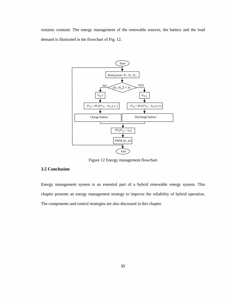
3.4.3 Energy Management System Algorithm
The objective of energy management system is to help maintain the power balance of the
hybrid system. In order to optimize the battery‘s charge and discharge state during the energy
conversion and increase its life time, the following conditions must be satisfied [85]
SOCmin ≤ SOC ≤ SOCmax (19)
In case when the battery is fully charged, the excess power can be dumped. This case has not
been studied due to limited resources of the current experimental system (no availability of a
dump load with automatic switches); however, it can be added to the ESS algorithm in future
work. As the output load is resistive its power can be maintained by maintaining DC-Link
voltage via the DC-Link voltage controller mentioned above. If the generated power is greater
than the demand DC-Link voltage goes up. So battery is charged with excess power and load
power remains constant. On the other hand, if the generated power is less than the demand DC-
Link voltage goes down. So battery discharges required power to the load and load power
+
_
Σ PI V*DC I*bat +
_
Σ PI PWM
Imax
_
+
+
_ Vbat VDC
Ibat
d1
d2
Imin
35
remains constant. The energy management of the renewable sources, the battery and the load
demand is illustrated in the flowchart of Fig. 12.
Figure 12 Energy management flowchart
3.5 Conclusion
Energy management system is an essential part of a hybrid renewable energy system. This
chapter presents an energy management strategy to improve the reliability of hybrid operation.
The components and control strategies are also discussed in this chapter.
Read power: PL, Pw, Ppv
YES NO
VDC↓
PWM (d1, d2)
I*bat = PI (V*DC– VDC): (+)
PI (I*bat – Ibat)
VDC↑
I*bat = PI (V*DC– VDC): (–)
Charge battery Discharge battery
End
Start
(Pw+Ppv) < PL

36
Chapter 4
Rapid Control Prototyping
4.1 Introduction
Since its introduction, real-time simulation has gained popularity among engineers and
researchers. Real time simulation is defined as a computer model of physical system that runs at
the same rate as the actual physical system [86]. That brings benefits like fault detection at an
early stage, increased productivity, reusability of the simulator and cost minimization.
Real-time simulation can be divided broadly in three types [87],[88].
1. Rapid control prototyping (RCP)
2. Hardware-in-Loop (HIL)
3. Pure Simulation (PS)
In rapid control prototyping application, a real-time simulator implements a plant controller
model and connects to a physical system via input and output ports of the simulator. On the other
hand, HIL can be used to test real controllers connected to simulated plant model. One advantage
of HIL is the low cost of simulated plant compared to real plant in RCP. Also, HIL helps to test a
system with low cost and without risk. In PS application, a real-time simulator simulates both the
controller model and the plant model [87],[88]. A depiction of this fact is shown in fig. 13.

37
The RCP kit includes hardware, software and accessories necessary to design and tests different
controllers. By using OPAL-RT‘s powerful real-time simulation tools along with Festo Didactic‘s
(formerly known as Lab-Volt) hardware, it is possible to design, troubleshoot and implement
simple to complex real-world control strategies. The RCP tool used in this study is RCP-
EC200W.
Figure 13 Application categories of Real Time Simulation System
4.2 RT-Lab Overview
The software used in this research work is RT-LAB version: v10.5.7.344. RT-LAB is a
distributed real-time platform that enables engineers and researchers to run Simulink dynamic
models at real-time with hardware-in-the-loop (HIL), at low cost, high accuracy and a very short
time. Its scalability allows the developer to add computing power where and when it is needed. It
is flexible enough to be applied to the most complex simulation and control problem, whether it is
a real-time hardware-in-the-Loop application or for speeding up model execution, control and test
[89]. The simulator used in this research is OP5600 real-time digital simulator.

38
4.3 Hardware & Software Details
4.3.1 OP5600 Real Time Simulator
The OP5600 is the core of RCP-EC200W system used in this research work. It is a complete
simulation system comprising a powerful computer, a flexible high-speed front-end processor and
a signal conditioning stage. With its multiple parallel cores, the OP5600 has the capacity to run,
in real-time, elaborated Matlab models that can represent complex physical system, its associated
controllers or both [90]. It‘s comprehensive set of digital and analog IO‘s enable‘s OP5600
interface to real world systems.
The technical benefits of this system are enhanced by OPAL-RT‘s software and the OP8660
signal conditioning module. The front panel of the OP5600 gives access through RJ45 connectors
to a large array of digital and analog IO‘s. Signals coming from the RJ45 connectors can be
routed into mini-BNC outputs (up to 16 channels) that can be monitored by oscilloscopes. For the
most part, even advanced users of the RCP-EC200W system will have access to all the OP5600‘s
IO‘s they may need through the OP8660 module with the added feature of having high voltage
and current conditioning. The OP5600 easily connects to the 8660 through clearly identified
DB37 connectors located on its back panel [90],[91]. The front view of OP5600 simulator is
shown in fig. 14.

39
Figure 14 Front view of OP5600 Real-Time Simulator
4.3.2 OP8660 Controller and data Acquisition Interface
The OP8660 controller and data acquisition interface is developed to enhance the usability of
OP5600 system by providing multiple conditioned IO channels specifically tailored for power
electronics and power systems applications. The OP8660 simplifies the connectivity between a
virtual environment (real-time simulator) and real experimental systems by providing a secure,
robust and easy to use interface.
The main feature of OP8660 is its high voltage and current probes. It can also output the firing
pulses to control two IGBT inverter modules and can read two ABZ position encoders. Finally
wide arrays of digital and analog IO‘s are available for the users [90],[91].
4.3.3 OPAL-RT’s RT-LAB Software
RT-LAB represents a complete software environment that integrates OPAL-RT‘s OP5600
simulator with the powerful graphical and model-based capabilities of Matlab‘s Simulink. The
process of having a Simulink model running in the OP5600 simulator is very illustrative of the

40
functionality and capacities of the RT-LAB software. This process can be summarized in the
following sequence:
1. A model is created in Simulink
2. Basic formatting and separation operations are carried out on the model to create sub-systems
that suit RT-LAB‘s manipulation.
3. RT-LAB‘s proprietary Simulink blocks are added to the model to allow communication among
model‘s sub-systems and between the model and the IO channels.
4. The model is compiled and the resulting C code is loaded into the real time simulator.
5. Once the model is running in the real time simulator a Simulink-based interface (i.e. console) is
created to give the user access in real time to the signals and parameters within the model.
At any time while the model is running RT-LAB allows: fully configuring the data acquisition
properties; modifying parameters of the system; monitoring the real time performance of the
simulator etc. [90],[91]. A more step by step procedure can be found in Appendix B.

41
4.4 RT-Lab Modeling for Real Time Monitoring
The real time model of hybrid wind solar system with battery storage is shown in Fig. 15.
Figure 15 Real time system for the HIL hybrid energy with storage system
Any Simulink model can be implemented in RT-LAB environment by performing the following
steps. The block diagram of the Simulink model must be modified by regrouping the model into
subsystems and inserting OpComm blocks. In RT-LAB, all the subsystems must be named with a
prefix identifying their function. The prefixes are console subsystem (SC_) and master subsystem
(SM_). For console subsystem (SC_), there is at most one OpComm in each real-time simulated
OP8660 data acquisition interface
Hardware-in-the loop
(HIL)
Simulink model executed in RT-Lab software
P
M
OP5600 real-time
simulator RT-Target
Command station-PC
Converters
Dynamometer (WT)
PV module
panel
Battery
storage
Variable Load
Real-Time Monitoring and Control

42
model. It contains all user interface blocks, such as scopes, displays, switches and gains, and this
subsystem will run asynchronously from the other subsystems. Each master subsystem in RT
LAB is represented by a core to perform their processes in efficient and fast way. In the RT-LAB
model, there is always one master subsystem in each model. Master subsystem (SM_) contains all
the computational elements of the model, the mathematical operations, the input and output
blocks, and the signal generators. After grouping the model, OpComm blocks must be added to
enable and save communication setup data. All inputs of subsystems must first go to OpComm
block before being used. The subsystems of the model in are shown in figure 16.
Figure 16 Model Subsystems in RT-Lab
The Simulink model is first compiled in RT-LAB. Then it is loaded in OP5600 real time
simulator for master subsystem. Finally all the subsystems are executed by OP5600 simulator.
Energy
management &
control algorithms
Speed
encoder
Currents/Voltage measurements
Pulses
Ref.
Results plotting
Results
storage
SM_Control
SC_Monitor
P
W
M

43
4.5 Conclusion
This chapter provides an overview of rapid control prototyping system RCP-EC200W. This
system consists of OP5600 Real Time Simulator, OP8660 Controller and data acquisition
interface and RT-LAB software. A description of how to execute the model in RT-LAB is also
provided.
44
Chapter 5
Experimentation & Results
5.1 Introduction
Experimental results of proposed laboratory scale hybrid wind solar energy system with
energy storage system are detailed in this chapter. Apart from the renewable sources, this hybrid
system consists of AC load, battery storage and control system for operation and monitoring.
Power electronics converters are used to allow controlling various devices in the hybrid system
such as maximum power point tracking (MPPT) from the renewable, DC-bus voltage and load
voltage/current regulation to increase the system‘s efficiency. In order to operate the system as a
sustainable energy system, battery storage is incorporated and an energy management system is
developed.
5.2 Experimental Setup
The experimental setup is shown in Fig. 17. It consists of four-quadrant dynamometer which
serves as wind turbine emulator, coupled with a permanent magnet synchronous generator
(PMSG), a commercial solar panel, industrial lamps for varying the irradiation, a lead acid
battery, power electronics converters, an encoder for generator speed measurement, inductive-
capacitive filter, a low power resistive load, a data acquisition interface (OP8660) with
current/voltage measurement inputs, 6-pulse inverter outputs and encoder input, and the Opal-RT
real-time simulator (OP5600). Opal-RT‘s real-time simulator has an Intel Xeon QuadCore 2.40
GHz processor which makes it a powerful tool for rapid control prototyping and Hardware-in-

45
Loop applications [92]. The control system is developed using MATLAB/Simulink. Then it is
compiled and built in RT-LAB. Finally the model is executed in real time using Opal-RT digital
simulator. The connection between all the components is shown in Fig. 18. The parameters of the
equipment‘s used in this experiment can be found in the appendix.
Figure 17 Experimental setup of the laboratory scale hybrid wind solar system with storage
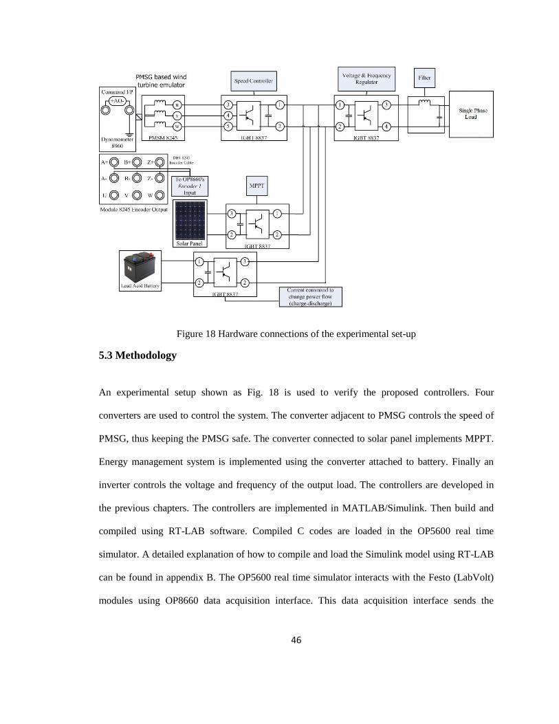
46
Figure 18 Hardware connections of the experimental set-up
5.3 Methodology
An experimental setup shown as Fig. 18 is used to verify the proposed controllers. Four
converters are used to control the system. The converter adjacent to PMSG controls the speed of
PMSG, thus keeping the PMSG safe. The converter connected to solar panel implements MPPT.
Energy management system is implemented using the converter attached to battery. Finally an
inverter controls the voltage and frequency of the output load. The controllers are developed in
the previous chapters. The controllers are implemented in MATLAB/Simulink. Then build and
compiled using RT-LAB software. Compiled C codes are loaded in the OP5600 real time
simulator. A detailed explanation of how to compile and load the Simulink model using RT-LAB
can be found in appendix B. The OP5600 real time simulator interacts with the Festo (LabVolt)
modules using OP8660 data acquisition interface. This data acquisition interface sends the

47
controller generated PWM‘s in OP5600 simulator to the real converters and inverter, thus
controlling the overall system.
5.4 Limitations
Due to the system constraints there are some limitations in the developed hybrid energy system.
We didn‘t consider the case of battery over charge. This problem could be solved using a
dumping load. But as there is no dump load with automatic switches available in the experimental
modules, this case is not considered. Also, there are some power generation mismatches in the
system. For example, 260 W solar panel outputs 8-10 W power. The reason behind that is the
irradiation and load. The solar panel is tested in the lab environment. The current generated from
the panel is low compared to the panel specification. The output power will greatly increase if the
panel is mounted outside. Also, the generator power is kept low due to the safe operation of wind
emulator, which in turns reduces the DC-Link voltage and the output voltage.
There are some abrupt changes in the experimental output due to the sudden change of power in
the sources and the perturbation from the converters. Other sources of experimental error include
the oscillation due to the gates‘ switching and manual starting and stopping of the hardware
modules.
5.5 Experimental Results
Several experimental cases are considered for validating the proposed control system of
hybrid renewable energy system based on wind and solar energy conversion system with battery
storage. Experiments were carried out based on wind turbine speed, solar irradiation, variable
load and low power conditions. Four scenarios are considered in this study.
1. System performance under variable wind power
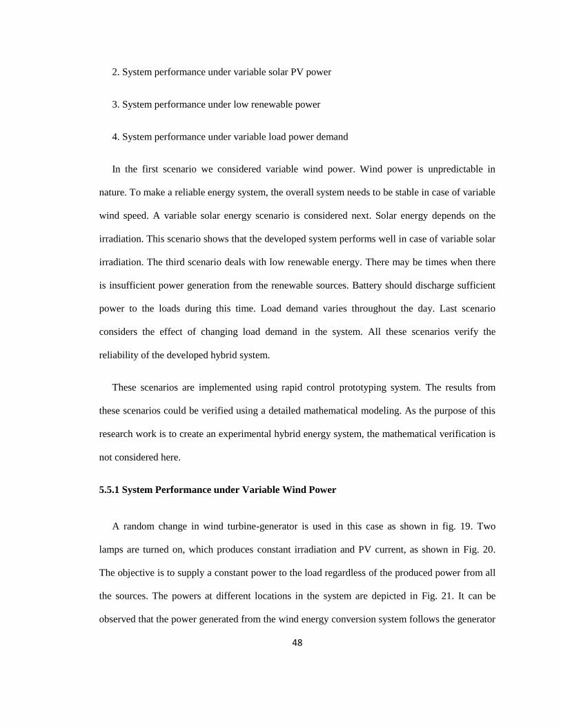
48
2. System performance under variable solar PV power
3. System performance under low renewable power
4. System performance under variable load power demand
In the first scenario we considered variable wind power. Wind power is unpredictable in
nature. To make a reliable energy system, the overall system needs to be stable in case of variable
wind speed. A variable solar energy scenario is considered next. Solar energy depends on the
irradiation. This scenario shows that the developed system performs well in case of variable solar
irradiation. The third scenario deals with low renewable energy. There may be times when there
is insufficient power generation from the renewable sources. Battery should discharge sufficient
power to the loads during this time. Load demand varies throughout the day. Last scenario
considers the effect of changing load demand in the system. All these scenarios verify the
reliability of the developed hybrid system.
These scenarios are implemented using rapid control prototyping system. The results from
these scenarios could be verified using a detailed mathematical modeling. As the purpose of this
research work is to create an experimental hybrid energy system, the mathematical verification is
not considered here.
5.5.1 System Performance under Variable Wind Power
A random change in wind turbine-generator is used in this case as shown in fig. 19. Two
lamps are turned on, which produces constant irradiation and PV current, as shown in Fig. 20.
The objective is to supply a constant power to the load regardless of the produced power from all
the sources. The powers at different locations in the system are depicted in Fig. 21. It can be
observed that the power generated from the wind energy conversion system follows the generator

49
speed and the wind speed. As the irradiation is constant solar panel generates a constant power.
The battery is charged with a power which follows the wind turbine power in order to maintain
the required power at the load. The DC-bus voltage, shown in Fig. 22, is almost constant with
small fluctuations around the voltage reference due to the changes in the wind turbine power and
the battery power. It can be seen in Fig. 21 wind power is 14W at 7 seconds into the simulation.
This along with solar power creates excess power in the system which charges the battery. Fig. 21
also shows that highest wind power generated was 26W at 20s. Battery also charged to 10W in
this time period. At t=35s, where the load power (Fig. 21.f) and the DC-bus voltage (Fig. 22)
slightly decreases due to the PV power change and the perturbation from the inverter (oscillation
due to the gates‘ switching), but rapidly reinstated to the appropriate values by the proposed
controller, which proves its robustness to unknown perturbations. The battery current generated is
shown in Fig. 23, follows the pattern of the wind power for an adequate charge of the battery.
Overall, the voltage and the current at the load are maintained constant, as shown in Fig. 24 and
25. Current remains within the limited region, as shown in Fig. 26, to keep constant load power
despite the sudden changes in the wind turbine power generation and the battery charge. The
frequency at the load side is constant as shown in Fig. 27. Table I summarizes above
observations. From these observations it is prominent that the developed system can handle the
variations in the wind power generation and give sufficient power to the load.
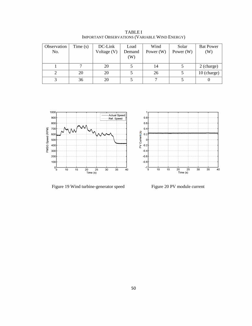
50
TABLE I IMPORTANT OBSERVATIONS (VARIABLE WIND ENERGY)
Observation
No.
Time (s) DC-Link
Voltage (V)
Load
Demand
(W)
Wind
Power (W)
Solar
Power (W)
Bat Power
(W)
1 7 20 5 14 5 2 (charge)
2 20 20 5 26 5 10 (charge)
3 36 20 5 7 5 0
Figure 19 Wind turbine-generator speed Figure 20 PV module current

51
Figure 21 Power at different locations in the system (variable wind power)

52
Figure 22 DC-bus voltage Figure 23 Battery current
Figure 24 Load Voltage (zoom) Figure 25 Load Current (zoom)
Figure 26 Load current Figure 27 Frequency

53
5.5.2 System Performance under Variable Solar PV Power
In this case, different numbers of lamps are used to vary the irradiation at different time
instants. The wind turbine is running at a constant speed which produced a constant power as
shown in Fig. 28.a. The PV panel power is varied based on the number of lamps turned on. This
fact is depicted in Fig. 28.c. This change in irradiations impacts the PV current as shown in Fig.
29. As the generated power is insufficient, battery discharged power following the variation of the
PV panel power to provide a constant power at the load shown in Fig. 28.d. But when power
generation from the PV starts to increase, battery charges power. The battery current is shown in
Fig. 30, which followed the PV panel power changes to maintain adequate load power. The DC-
bus voltage is constant, as shown in Fig. 31, despite the changes at the solar panel. The solar
panel generates highest amount of 8W power at time instants 6s and 35s. In this period of time,
the hybrid system generates more power than the load demand. This excess power of 6W goes to
the battery. At 20s solar power reduces to 2W. But the overall power generation from the hybrid
system is just enough to fulfill the load demand. So the battery neither charge nor discharge at
that time. After 23s solar power starts to increase, thus increasing the overall power generation
from the hybrid system. It can be seen that battery is charged with excess power in this period of
time. There are some interesting observations after the time instants t=15s and t=25s, where the
load power (Fig. 28.f) and the DC-bus voltage (Fig. 31) slightly decreased and increased
respectively due to the PV power change and the perturbation from the inverter (oscillation due to
the gates‘ switching), but rapidly reinstated to the appropriate values by the proposed controller.
The load voltage is well regulated and maintained within a limited region as shown in Fig. 32.
These results verify that the developed system can reliably supply power to the load in case of
changing irradiation. Table II summarizes above observations.
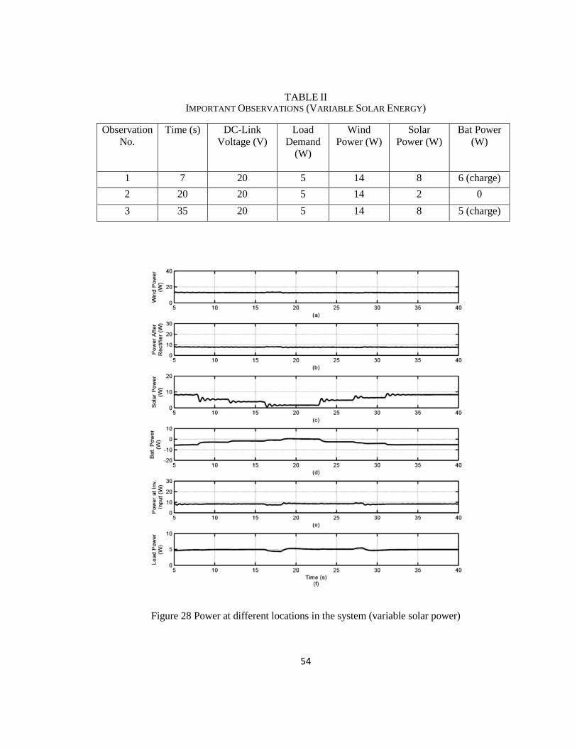
54
TABLE II IMPORTANT OBSERVATIONS (VARIABLE SOLAR ENERGY)
Observation
No.
Time (s) DC-Link
Voltage (V)
Load
Demand
(W)
Wind
Power (W)
Solar
Power (W)
Bat Power
(W)
1 7 20 5 14 8 6 (charge)
2 20 20 5 14 2 0
3 35 20 5 14 8 5 (charge)
Figure 28 Power at different locations in the system (variable solar power)

55
Figure 29 PV module current Figure 30 Battery current
Figure 31 DC bus voltage Figure 32 Load voltage (zoom)
5.5.3 System Performance under Low Renewable Power
In this case, the behavior of the proposed system is investigated under low renewable power of
the sources. The wind turbine-geneartor speed reaches its minimum value at t= 15s, as shown in
Fig. 33, and the PV panel power generation decreases by turning OFF the lamps one by one as
can be observed in its current shown in Fig. 34. Due to these conditions, the total power from the
renewable sources drops to zero, after t=15 s for the wind turbine and t=30s for the PV panel, as
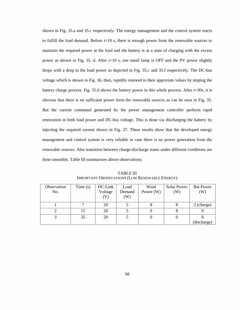
56
shown in Fig. 35.a and 35.c respectively. The energy management and the control system reacts
to fulfill the load demand. Before t=10 s, there is enough power from the renewable sources to
maintain the required power at the load and the battery is at a state of charging with the excess
power as shown in Fig. 35. d. After t=10 s, one small lamp is OFF and the PV power slightly
drops with a drop in the load power as depicted in Fig. 35.c and 35.f respectively. The DC-bus
voltage which is shown in Fig. 36, then, rapidily restored to their approriate values by stoping the
battery charge process. Fig. 35.d shows the battery power in this whole process. After t=30s, it is
obvious that there is no sufficient power form the renewable sources as can be seen in Fig. 35.
But the current command generated by the power management controller perform rapid
restoration in both load power and DC-bus voltage. This is done via discharging the battery by
injecting the required current shown in Fig. 37. These results show that the developed energy
management and control system is very reliable in case there is no power generation from the
renewable sources. Also transition between charge-discharge states under different conditions are
done smoothly. Table III summarizes above observations.
TABLE III IMPORTANT OBSERVATIONS (LOW RENEWABLE ENERGY)
Observation
No.
Time (s) DC-Link
Voltage
(V)
Load
Demand
(W)
Wind
Power (W)
Solar Power
(W)
Bat Power
(W)
1 7 20 5 8 8 2 (charge)
2 15 20 5 0 8 0
3 35 20 5 0 0 8
(discharge)
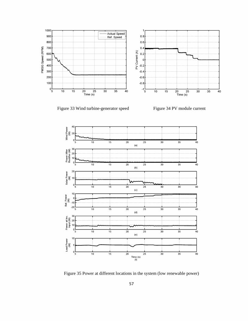
57
Figure 33 Wind turbine-generator speed Figure 34 PV module current
Figure 35 Power at different locations in the system (low renewable power)
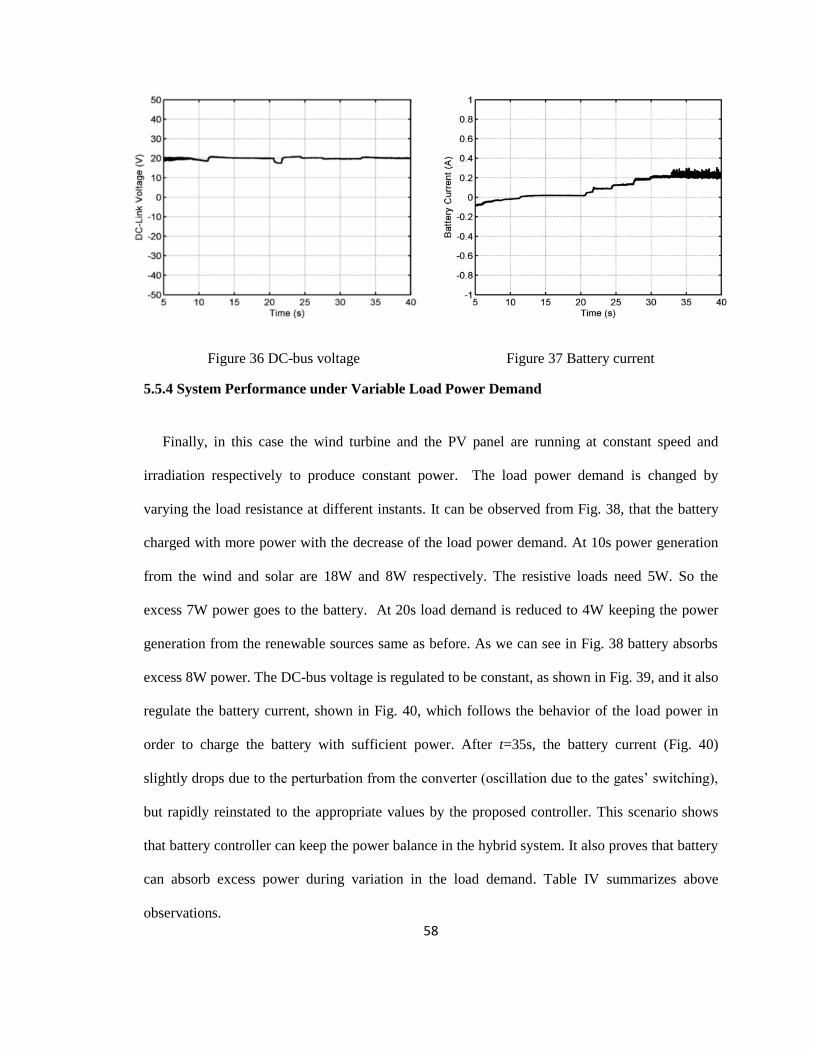
58
Figure 36 DC-bus voltage Figure 37 Battery current
5.5.4 System Performance under Variable Load Power Demand
Finally, in this case the wind turbine and the PV panel are running at constant speed and
irradiation respectively to produce constant power. The load power demand is changed by
varying the load resistance at different instants. It can be observed from Fig. 38, that the battery
charged with more power with the decrease of the load power demand. At 10s power generation
from the wind and solar are 18W and 8W respectively. The resistive loads need 5W. So the
excess 7W power goes to the battery. At 20s load demand is reduced to 4W keeping the power
generation from the renewable sources same as before. As we can see in Fig. 38 battery absorbs
excess 8W power. The DC-bus voltage is regulated to be constant, as shown in Fig. 39, and it also
regulate the battery current, shown in Fig. 40, which follows the behavior of the load power in
order to charge the battery with sufficient power. After t=35s, the battery current (Fig. 40)
slightly drops due to the perturbation from the converter (oscillation due to the gates‘ switching),
but rapidly reinstated to the appropriate values by the proposed controller. This scenario shows
that battery controller can keep the power balance in the hybrid system. It also proves that battery
can absorb excess power during variation in the load demand. Table IV summarizes above
observations.
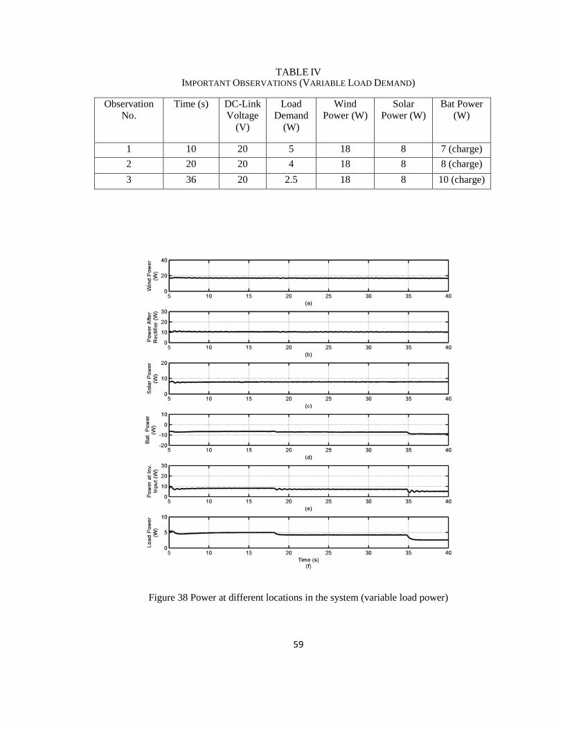
59
TABLE IV IMPORTANT OBSERVATIONS (VARIABLE LOAD DEMAND)
Observation
No.
Time (s) DC-Link
Voltage
(V)
Load
Demand
(W)
Wind
Power (W)
Solar
Power (W)
Bat Power
(W)
1 10 20 5 18 8 7 (charge)
2 20 20 4 18 8 8 (charge)
3 36 20 2.5 18 8 10 (charge)
Figure 38 Power at different locations in the system (variable load power)

60
Figure 39 DC bus voltage Figure 40 Battery current
5.6 Conclusion
In this chapter the experimental results for the proposed control system is discussed. The
experimental results show that the power is smoothly transferred to the battery when sources and
load conditions change. A stable DC-bus voltage is guaranteed during the changing conditions
and the power at the load is also maintained. The result also shows that the hybrid system can
provide power to the loads reliably in different conditions.
61
Chapter 6
Conclusion
A hybrid wind-solar energy system can provide both environment friendly and cost effective
approach to generate energy. This will help remote communities where grid connected supply is
unavailable. A hybrid renewable energy system (HRES), based on wind and solar energy sources
with battery storage, and control schemes are detailed in this research work. Energy management
and control strategies are developed to harness maximum power from the renewable sources and
to coordinate the power exchange between the sources, the battery and the load. The experimental
results show that the power is smoothly transferred to the battery when sources and load
conditions change. Also, a stable DC-bus voltage is guaranteed during the changing conditions
and the power at the load is maintained. The proposed experimental HRES can be used as an
education and research tool to understand and develop various configurations of hybrid systems
and advanced control applications.
6.1 Contribution
The main contributions of this research work are summarized below:
1) Development of an experimental laboratory model for wind energy conversion system
(WECS), solar energy conversion system and apply maximum power point tracking algorithm to
extract maximum power.
2) Development of an experimental laboratory model for standalone wind-solar energy system
with battery storage.

62
3) Development of a battery charging-discharging system to use the battery as a back-up power in
this hybrid system.
4) Development of an energy management system to share the power generated by the hybrid
system, to increase the system reliability.
6.2 Recommendations for future work
The controllers used in the proposed HRES are based on proportional-Integral (PI) control and
vector control scheme. It is possible to improve the performance using advanced controllers such
as fuzzy logic, neural network, predictive control etc. Also, the energy management in this
research work is based on DC-Link voltage. It can be improved further by including different
cases. Battery charging discharging can be improved using state of charge (SOC) in the control
logic. Further, research can be conducted to improve the reliability and the power quality of the
system. Depending on the utility size, it is possible to improve the energy management system by
including more conditions and complex cases. Grid integration of such complex system would be
very challenging and further research can be conducted in this area to improve the reliability and
power quality.

63
Appendix
A. Specifications
TABLE V PARAMETERS OF THE HRES
Load (W) 5
DC-Link Voltage (V) 20
Frequency (Hz) 60
TABLE VI PARAMETERS OF THE EMULATED WIND TURBINE
Number of blades 3
Air density (kg/m2) 1.225
Diameter (m) 1.15
Pulley ratio 24:12
Moment of inertia-Jr(kg·m2) 0.028
TABLE VII
SPECIFICATIONS OF CS6P-260M PV MODULE UNDER STANDARD TEST CONDITION
Maximum Power (W) 260
Open Circuit Voltage (V) 37.8
Maximum Power Point Voltage (V) 30.7
Short Circuit Current (A) 8.99
Maximum Power Point Current (A) 8.48
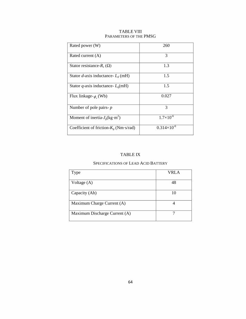
64
TABLE VIII PARAMETERS OF THE PMSG
Rated power (W) 260
Rated current (A) 3
Stator resistance-Rs (Ω) 1.3
Stator d-axis inductance- Ld (mH) 1.5
Stator q-axis inductance- Lq(mH) 1.5
Flux linkage-v (Wb) 0.027
Number of pole pairs- p 3
Moment of inertia-Jg(kg·m2) 1.7×10
-6
Coefficient of friction-Kg (Nm·s/rad) 0.314×10⁻⁶
TABLE IX
SPECIFICATIONS OF LEAD ACID BATTERY
Type VRLA
Voltage (A) 48
Capacity (Ah) 10
Maximum Charge Current (A) 4
Maximum Discharge Current (A) 7

65
B. Steps required for executing Simulink model in RT-Lab
The following steps are required to start simulation using RT-Lab
1. Connect the OP5600 simulator to the OP8660 as shown in section 3.1 in the hardware user
guide of High-Performance Real-Time Simulation and HIL Test Systems [93].
2. Connect the OP5600 simulator with the host computer as shown in section 3.2 in the
hardware user guide.
3. Turn ON the OP5600 Real-time Digital Simulator.
4. Open RT-LAB in the host computer.
5. Make sure the ‗Targets‘ in ‗Project Explorer‘ window is connected with LCSM. To update the
connection status, right click on the target LCSM and click Refresh. In case of failure to
connect, check the blue LAN/Network cable.
6. Create a new RT-LAB Project or access an existing RT-LAB Project (i.e. TEST).
7. Minimize RT-LAB, copy the required basic files, create a new folder (i.e. Control) in the
following directory and paste all the files;
Local Disk (C:) > Users> Professor Adel > workspaces > TEST > models > Control
The folder must contain the Simulink model (.mdl) file named HRES.mdl, one (.bin) file and
one (.conf) file. Both .bin and .conf files are required to define how the data acquisition
read/write channels are assigned. Rename the file if required.
8. To import Simulink model, double click on the project, right click on Models, go to Add
select Existing Model. From the window click Import and select the file from the same
directory where the model file (.mdl) was pasted before.
Local Disk (C:) > Users> Professor Adel > workspaces > TEST1 > models > Control
9. Open the RT-LAB window and select the imported file on the project.

66
10. To apply new control algorithm and modify/update the model, right click on the Simulink
model, go to Edit with and select Matlab R2011B (32bit) 7.13. A new Matlab/Simulink
window will appear to apply different control schemes and update the model as desired.
11. Perform the connection depicted in Fig.18 between the OP8660 signal conditioning module
and Lab-Volt‘s hardware. Make sure that the plugs of the DB9-8245 encoder cable are
correctly connected to their corresponding encoder outputs in the front panel of the 8245
module.
12. Make sure that the selected converters and the PMSM module are fed through its 24V DC
input, as shown in section 3.4.2 (hardware user guide). Turn ON the selected inverter.
13. Turn ON the power input for the 8960-20 Dynamometer and make sure the USB cable is
connected with the host computer.
14. Open LVDAC-EMS software from the start menu. Select the network voltage and frequency,
120V-60Hz, and then click Ok.
15. A new LVDAC-EMS window will appear. From the Tool menu select Four-Quadrant
Dynamometer/Power Supply.
16. To run the 8960 Dynamometer as an Emulator, modification is required in the Function
Settings, change the Function to Wind-Turbine Emulator and change Function Setting as per
Fig. 41.

67
Figure 41 Function selection and settings in LVDAC-EMS window
17. Save the model after modifying/updating, check the Development tab in RT-LAB and make
sure that the Target Platform is set to Redhat for the selected Simulink model.
18. Check the Execution tab and make sure that the Real-time Simulation Mode is set to
Hardware Synchronized.
19. To compile the simulation model click on Build, make sure the proper Simulink model is
selected for compilation.
20. Click on the Assignation tab and make sure that the Extra High Performance (XHP) mode in
ON. Check the box to turn ON the XHP mode.
21. To upload the model in the real-time simulator, click Load. Errors may appear while loading,
look for the error description in the Display tab and load again after correcting them.

68
22. If the model is successfully loaded a monitoring console will appear automatically in a new
Matlab/Simulink window. The console can be identified by a yellow note titled as
‘Automatically generated by RT-LAB during compilation’.
23. Click Execute to run the model.
24. From the LVDAC console use slider to run the system with variable speed. The user console
will allow user to modify the references of the machine during the operation.
69
References
[1] G. Legros and World Health Organization, The Energy Access Situation in Developing
Countries: A Review Focusing on the Least Developed Countries and Sub-Saharan Africa. World
Health Organization, 2009.
[2] ―Natural Resources Canada,‖ [Online]. Available: http://www.nrcan.gc.ca/energy/electricity-
infrastructure/about-electricity/7359.
[3] ―Natural Resources Canada,‖ [Online]. Available: http://www.nrcan.gc.ca/energy/electricity-
infrastructure/about-electricity/7295.
[4] J. Royer, "Status of Remote/Off-Grid Communities in Canada," Natural Resources
Canada,[online].Available: Http://www.Nrcan.Gc.ca/energy/publications/sciences-
technology/renewable/smart-grid/11916, 2011.
[5] National Energy Board, "Energy supply and demand projections to 2040 - energy market
assessmen," 2016.
[6] ―Wind Energy TechnoCentre,‖ [Online]. Available:
https://www.eolien.qc.ca/en/infrastructures-en/microgrid-wind-diesel.html.
[7] Y. Chen, C. Cheng and H. Wu, "Grid-connected hybrid PV/wind power generation system
with improved DC bus voltage regulation strategy," in Applied Power Electronics Conference
and Exposition, 2006. APEC'06. Twenty-First Annual IEEE, 2006, pp. 7 pp.
[8] X. Li, D. Zhang, Y. Li and Y. Xu, "Multi-string photovoltaic grid-connected inverter based on
alternate single-phase PWM control," in Power and Energy Engineering Conference (APPEEC),
2012 Asia-Pacific, 2012, pp. 1-4.
[9] F. Prutianu and V. Popescu, "Control of single phase inverters for wind energy conversion
using PWM techniques," in Electronics and Telecommunications (ISETC), 2010 9th International
Symposium on, 2010, pp. 95-98.
[10] M. Almi and M. Marrouf, "Connection of photovoltaic generator to domestic three phase
electrical network supply trough voltage source inverter," in Proceedings of the International
Symposium on Environment Friendly Energies in Electrical Applications (EFEEA), 2010, pp. 2-
4.
[11] E. Milton Filho, J. R. Gazoli and J. S. Alfeu Filho, "A control method for voltage source
inverter without dc link capacitor," in Power Electronics Specialists Conference, 2008. PESC
2008. IEEE, 2008, pp. 4432-4437.

70
[12] M. Dali, J. Belhadj and X. Roboam, "Hybrid solar–wind system with battery storage
operating in grid-connected and standalone mode: control and energy management–experimental
investigation," Energy, vol. 35, pp. 2587-2595, 2010.
[13] N. A. Ahmed, A. Al-Othman and M. AlRashidi, "Development of an efficient utility
interactive combined wind/photovoltaic/fuel cell power system with MPPT and DC bus voltage
regulation," Electr. Power Syst. Res., vol. 81, pp. 1096-1106, 2011.
[14] D. Das, R. Esmaili, L. Xu and D. Nichols, "An optimal design of a grid connected hybrid
wind/photovoltaic/fuel cell system for distributed energy production," in Industrial Electronics
Society, 2005. IECON 2005. 31st Annual Conference of IEEE, 2005, pp. 6 pp.
[15] R. Esmaili, L. Xu and D. Nichols, "A new control method of permanent magnet generator
for maximum power tracking in wind turbine application," in Power Engineering Society General
Meeting, 2005. IEEE, 2005, pp. 2090-2095.
[16] D. Bo, Y. Li and Z. Zheng, "Energy management of hybrid DC and AC bus linked
microgrid," in Power Electronics for Distributed Generation Systems (PEDG), 2010 2nd IEEE
International Symposium on, 2010, pp. 713-716.
[17] Z. Jiang and X. Yu, "Active power—Voltage control scheme for islanding operation of
inverter-interfaced microgrids," in Power & Energy Society General Meeting, 2009. PES'09.
IEEE, 2009, pp. 1-7.
[18] T. Nie, Q. Wei and D. Shao, "A fuzzy and decoupled dq based inverter control strategy for
microgrid in islanding operation," in Strategic Technology (IFOST), 2011 6th International
Forum on, 2011, pp. 425-428.
[19] Y. W. Li and C. Kao, "An accurate power control strategy for power-electronics-interfaced
distributed generation units operating in a low-voltage multibus microgrid," Power Electronics,
IEEE Transactions on, vol. 24, pp. 2977-2988, 2009.
[20] J. M. Guerrero, J. Matas, D. Vicuna, L. García, M. Castilla and J. Miret, "Wireless-control
strategy for parallel operation of distributed-generation inverters," Industrial Electronics, IEEE
Transactions on, vol. 53, pp. 1461-1470, 2006.
[21] J. Matas, M. Castilla, L. G. de Vicuña, J. Miret and J. C. Vasquez, "Virtual impedance loop
for droop-controlled single-phase parallel inverters using a second-order general-integrator
scheme," Power Electronics, IEEE Transactions on, vol. 25, pp. 2993-3002, 2010.
[22] J. M. Guerrero, D. Vicuña, L. García, J. Matas, M. Castilla and J. Miret, "Output impedance
design of parallel-connected UPS inverters with wireless load-sharing control," Industrial
Electronics, IEEE Transactions on, vol. 52, pp. 1126-1135, 2005.
[23] H. Li and Z. Chen, "Design optimization and site matching of direct-drive permanent magnet
wind power generator systems," Renewable Energy, vol. 34, pp. 1175-1184, 2009.
71
[24] S. Liu, S. Li and L. He, "Direct-driven permanent magnet synchronous wind-power
generating system with two three-level converters based on SVPWM control," Procedia
Engineering, vol. 29, pp. 1191-1195, 2012.
[25] J. S. Thongam, R. Beguenane, M. Tarbouchi, A. F. Okou, A. Merabet, I. Fofana and P.
Bouchard, "A rotor speed estimation algorithm in variable speed permanent magnet synchronous
generator wind energy conversion system," International Journal of Robust and Nonlinear
Control, vol. 23, pp. 1880-1890, 2013.
[26] C. Jauch, S. M. Islam, P. Sørensen and B. B. Jensen, "Design of a wind turbine pitch angle
controller for power system stabilisation," Renewable Energy, vol. 32, pp. 2334-2349, 2007.
[27] A. Haruni, M. Haque, A. Gargoom and M. Negnevitsky, "Control of a direct drive IPM
synchronous generator based variable speed wind turbine with energy storage," in IECON 2010-
36th Annual Conference on IEEE Industrial Electronics Society, 2010, pp. 457-563.
[28] A. Merabet, R. Beguenane, J. S. Thongam and I. Hussein, "Adaptive sliding mode speed
control for wind turbine systems," in IECON 2011-37th Annual Conference on IEEE Industrial
Electronics Society, 2011, pp. 2461-2466.
[29] T. Esram and P. L. Chapman, "Comparison of photovoltaic array maximum power point
tracking techniques," IEEE Transactions on Energy Conversion EC, vol. 22, pp. 439, 2007.
[30] G. Carannante, C. Fraddanno, M. Pagano and L. Piegari, "Experimental performance of
MPPT algorithm for photovoltaic sources subject to inhomogeneous insolation," Industrial
Electronics, IEEE Transactions on, vol. 56, pp. 4374-4380, 2009.
[31] H. Al-Atrash, I. Batarseh and K. Rustom, "Effect of measurement noise and bias on hill-
climbing MPPT algorithms," Aerospace and Electronic Systems, IEEE Transactions on, vol. 46,
pp. 745-760, 2010.
[32] R. A. Mastromauro, M. Liserre and A. Dell'Aquila, "Control issues in single-stage
photovoltaic systems: MPPT, current and voltage control," Industrial Informatics, IEEE
Transactions on, vol. 8, pp. 241-254, 2012.
[33] A. K. Abdelsalam, A. M. Massoud, S. Ahmed and P. Enjeti, "High-performance adaptive
perturb and observe MPPT technique for photovoltaic-based microgrids," Power Electronics,
IEEE Transactions on, vol. 26, pp. 1010-1021, 2011.
[34] D. Sera, R. Teodorescu, J. Hantschel and M. Knoll, "Optimized maximum power point
tracker for fast changing environmental conditions," in Industrial Electronics, 2008. ISIE 2008.
IEEE International Symposium on,2008, pp. 2401-2407.
[35] B. N. Alajmi, K. H. Ahmed, S. J. Finney and B. W. Williams, "Fuzzy-logic-control approach
of a modified hill-climbing method for maximum power point in microgrid standalone
photovoltaic system," Power Electronics, IEEE Transactions on, vol. 26, pp. 1022-1030, 2011.
72
[36] W. Jwo, C. Tong and C. Chao, "Firmware implementation of an adaptive solar cell
maximum power point tracking based on PSoC," in Photovoltaic Specialists Conference (PVSC),
2010 35th IEEE, 2010, pp. 000407-000411.
[37] S. Kebaili and A. Betka, "Design and simulation of stand alone photovoltaic
systems," WSEAS Transactions on Power Systems, vol. 6, pp. 89-99, 2011.
[38] M. A. Elgendy, B. Zahawi and D. J. Atkinson, "Assessment of the incremental conductance
maximum power point tracking algorithm," Sustainable Energy, IEEE Transactions on, vol. 4,
pp. 108-117, 2013.
[39] B. Yu, G. Yu and Y. Kim, "Design and experimental results of improved dynamic MPPT
performance by EN50530," in Telecommunications Energy Conference (INTELEC), 2011 IEEE
33rd International, 2011, pp. 1-4.
[40] A. Al Nabulsi and R. Dhaouadi, "Efficiency optimization of a DSP-based standalone PV
system using fuzzy logic and dual-MPPT control," Industrial Informatics, IEEE Transactions
on, vol. 8, pp. 573-584, 2012.
[41] H. H. Lee, L. M. Phuong, P. Q. Dzung, N. T. D. Vu and L. D. Khoa, "The new maximum
power point tracking algorithm using ANN-based solar PV systems," in TENCON 2010-2010
IEEE Region 10 Conference, 2010, pp. 2179-2184.
[42] B. Singh and G. K. Kasal, "Solid state voltage and frequency controller for a stand alone
wind power generating system," Power Electronics, IEEE Transactions on, vol. 23, pp. 1170-
1177, 2008.
[43] Y. Xue, L. Chang, S. B. Kjær, J. Bordonau and T. Shimizu, "Topologies of single-phase
inverters for small distributed power generators: an overview," Power Electronics, IEEE
Transactions on, vol. 19, pp. 1305-1314, 2004.
[44] A. Roshan, R. Burgos, A. C. Baisden, F. Wang and D. Boroyevich, "A DQ frame controller
for a full-bridge single phase inverter used in small distributed power generation systems,"
in Applied Power Electronics Conference, APEC 2007-Twenty Second Annual IEEE, 2007, pp.
641-647.
[45] D. N. Zmood and D. G. Holmes, "Stationary frame current regulation of PWM inverters with
zero steady-state error," Power Electronics, IEEE Transactions on, vol. 18, pp. 814-822, 2003.
[46] D. Dong, T. Thacker, R. Burgos, D. Boroyevich, F. Wang and B. Giewont, "Control design
and experimental verification of a multi-function single-phase bidirectional PWM converter for
renewable energy systems," inPower Electronics and Applications, 2009. EPE'09. 13th European
Conference on, 2009, pp. 1-10.
[47] R. Bojoi, L. R. Limongi, D. Roiu and A. Tenconi, "Enhanced power quality control strategy
for single-phase inverters in distributed generation systems," Power Electronics, IEEE
Transactions on, vol. 26, pp. 798-806, 2011.

73
[48] Y. Tzou, R. Ou, S. Jung and M. Chang, "High-performance programmable AC power source
with low harmonic distortion using DSP-based repetitive control technique," Power Electronics,
IEEE Transactions on, vol. 12, pp. 715-725, 1997.
[49] N. Mendis, K. M. Muttaqi and S. Perera, "Management of battery-supercapacitor hybrid
energy storage and synchronous condenser for isolated operation of PMSG based variable-speed
wind turbine generating systems,"Smart Grid, IEEE Transactions on, vol. 5, pp. 944-953, 2014.
[50] A. M. Gee, F. V. P. Robinson and R. W. Dunn, "Analysis of Battery Lifetime Extension in a
Small-Scale Wind-Energy System Using Supercapacitors," IEEE Transactions on Energy
Conversion, vol. 28, pp. 24-33, 2013.
[51] Y. Zhang, Z. Jiang and X. Yu, "Control strategies for Battery/Supercapacitor hybrid energy
storage systems," in Energy 2030 Conference, 2008. ENERGY 2008. IEEE, 2008, pp. 1-6.
[52] C. Abbey and G. Joos, "Supercapacitor Energy Storage for Wind Energy
Applications," IEEE Transactions on Industry Applications, vol. 43, pp. 769-776, 2007.
[53] N. R. Tummuru, M. K. Mishra and S. Srinivas, "Dynamic Energy Management of Hybrid
Energy Storage System With High-Gain PV Converter," IEEE Transactions on Energy
Conversion, vol. 30, pp. 150-160, 2015.
[54] H. Jou, Y. Chang, J. Wu and K. Wu, "Operation strategy for a lab-scale grid-connected
photovoltaic generation system integrated with battery energy storage," Energy Conversion and
Management, vol. 89, pp. 197-204, 1/1, 2015.
[55] R. Sebastián and R. P. Alzola, "Simulation of an isolated Wind Diesel System with battery
energy storage," Electr. Power Syst. Res., vol. 81, pp. 677-686, 2, 2011.
[56] S. Sinha and S. S. Chandel, "Review of recent trends in optimization techniques for solar
photovoltaic–wind based hybrid energy systems," Renewable and Sustainable Energy
Reviews, vol. 50, pp. 755-769, 10, 2015.
[57] O. Anaya-Lara, N. Jenkins, J. Ekanayake, P. Cartwright and M. Hughes, Wind Energy
Generation: Modelling and Control, John Wiley & Sons, 2009.
[58] Turbine Emulator, LabVolt Series, 8968-30, Festo Didactic, 2015. [Online]. Available:
https://www.labvolt.com/downloads/datasheet_50-8968-3_en.pdf
[59] P. Sharma, W. Sulkowski and B. Hoff, "Dynamic stability study of an isolated wind-diesel
hybrid power system with wind power generation using IG, PMIG and PMSG: A
comparison," International Journal of Electrical Power & Energy Systems, vol. 53, pp. 857-866,
12, 2013.
[60] M. Chinchilla, S. Arnaltes and J. C. Burgos, "Control of permanent-magnet generators
applied to variable-speed wind-energy systems connected to the grid," IEEE Transactions on
Energy Conversion, vol. 21, pp. 130-135, 2006.

74
[61] Y. Yang, K. T. Mok, S. C. Tan and S. Y. . Hui, "Nonlinear Dynamic Power Tracking of
Low-Power Wind Energy Conversion System," IEEE Transactions on Power Electronics, vol.
30, pp. 5223-5236, 2015.
[62] V. Rajasekaran, "Modeling, simulation and development of supervision control system for
hybrid wind diesel system," 2013.
[63] MathWorks Inc., ―Mathworks Documentation Center, Simpower Systems,‖ 2014. [Online].
Available : http://www.mathworks.com/help/physmod/sps/powersys/index.html.
[64] T. Salmi, M. Bouzguenda, A. Gastli and A. Masmoudi, "Matlab/simulink based modeling of
photovoltaic cell," International Journal of Renewable Energy Research (IJRER), 2012.
[65] M. A. Islam, A. Merabet, R. Beguenane and H. Ibrahim, "Modeling solar photovoltaic cell
and simulated performance analysis of a 250W PV module," in Electrical Power & Energy
Conference (EPEC), 2013 IEEE, 2013, pp. 1-6.
[66] D. P. Hohm and M. E. Ropp, "Comparative study of maximum power point tracking
algorithms using an experimental, programmable, maximum power point tracking test bed,"
in Photovoltaic Specialists Conference, 2000. Conference Record of the Twenty-Eighth
IEEE, 2000, pp. 1699-1702.
[67] V. Salas, E. Olías, A. Barrado and A. Lázaro, "Review of the maximum power point tracking
algorithms for stand-alone photovoltaic systems," Solar Energy Mater. Solar Cells, vol. 90, pp.
1555-1578, 7/6, 2006.
[68] Y. Nakata, K. Fujiwara, M. Yoshida, J. Itoh and Y. Okazaki, "Output voltage control for
PWM inverter with electric double layer capacitor as DC power supply," in Power Electronics
Conference (IPEC), 2010 International,2010, pp. 3099-3104.
[69] A. Meskani, A. Haddi and M. Becherif, "Modeling and simulation of a hybrid energy source
based on solar energy and battery," Int J Hydrogen Energy, vol. 40, pp. 13702-13707, 10/19,
2015.
[70] J. Appelbaum and R. Weiss, "An electrical model of the lead-acid battery,"
in Telecommunications Energy Conference, 1982. INTELEC 1982. International, 1982, pp. 304-
307.
[71] H. He, R. Xiong and J. Fan, "Evaluation of Lithium-Ion Battery Equivalent Circuit Models
for State of Charge Estimation by an Experimental Approach," Energies, vol. 4, pp. 582-598,
2011.
[72] A. Ter-Gazarian, Energy Storage for Power Systems. IET, 2011.
[73] C. L. Mantell, Batteries and Energy Systems. McGraw-Hill, 1983.
75
[74] Z. Yanlin, L. Peihong, Z. Qiuyun and C. Wen, "Separation of cadmium(II) from spent
nickel/cadmium battery by emulsion liquid membrane," The Canadian Journal of Chemical
Engineering, vol. 88, pp. 95-100, 2010.
[75] D. Berndt, Maintenance-Free Batteries: Lead-Acid, Nickel/Cadmium, Nickel/Hydride: A
Handbook of Battery Technology. Research Studies Press, 1997.
[76] J. Lee, K. Lee and J. Lee, "Self-discharge behaviour of sealed Ni-MH batteries using MmNi
3.3+ x Co 0.7 Al 1.0− x anodes," Journal of Alloys and Compounds, vol. 232, pp. 197-203, 1996.
[77] H. A. Kiehne, Battery Technology Handbook. CRC Press, 2003.
[78] A. M. Bernardes, D. C. R. Espinosa and J. A. S. Tenório, "Recycling of batteries: a review of
current processes and technologies," J. Power Sources, vol. 130, pp. 291-298, 5/3, 2004.
[79] T. Ma, H. Yang, L. Lu and J. Peng, "Technical feasibility study on a standalone hybrid solar-
wind system with pumped hydro storage for a remote island in Hong Kong," Renewable
Energy, vol. 69, pp. 7-15, 9, 2014.
[80] H. Akagi and H. Sato, "Control and performance of a doubly-fed induction machine intended
for a flywheel energy storage system," IEEE Transactions on Power Electronics, vol. 17, pp.
109-116, 2002.
[81] I. Glendenning, "Compressed air storage," Physics in Technology, vol. 12, pp. 103-110,
1981.
[82] C. Wang and M. H. Nehrir, "Power Management of a Stand-Alone Wind/Photovoltaic/Fuel
Cell Energy System," IEEE Transactions on Energy Conversion, vol. 23, pp. 957-967, 2008.
[83] M. H. Rashid, Power Electronics: Circuits, Devices, and Applications. Pearson Education
India, 2003.
[84] H. Fan, "Design Tips for an Efficient Non-inverting Buck-Boost," Analog Applications
Journal, 2014.
[85] L. Xu, X. Ruan, C. Mao, B. Zhang and Y. Luo, "An Improved Optimal Sizing Method for
Wind-Solar-Battery Hybrid Power System," IEEE Transactions on Sustainable Energy, vol. 4,
pp. 774-785, 2013.
[86] Wikipedia, Real-time simulation, 2016 [online]
Available: https://en.wikipedia.org/wiki/Real-time_simulation.
[87] J. Belanger, P. Venne and J. N. Paquin, "The What, Where, and Why of Real
Time Simulation." OPAL-RT Publication, 2010.

76
[88] C. Dufour, C. Andrade and B. langer, "Real-time simulation technologies in education: A
link to modern engineering methods and practices," in 11Th
International Conference on
Engineering and Technology Education, 2010.
[89] "RT-LAB user guide." Opal-RT Technologies Inc., 2007.
[90] "Real-time HIL/RCP laboratory," OPAL-RT Technologies Inc., 2013.
[91] "0.2kW electrical motor laboratory kit," Opal-RT Technologies Inc., 2013.
[92] "Rapid control prototyping energy conversion kit (RCP-EC200): Quick start guide," Opal-
RT Technologies, Inc., 2013.
[93] "High performance real-time simulation and HIL test system," Opal-RT Technologies Inc.,
2013.