energy harvesting for wireless …eh-network.org/events/dissemination2011/presentations/rob van...©...
TRANSCRIPT

© IMEC 2011 / CONFIDENTIAL
ENERGY HARVESTING FOR WIRELESS
AUTONOMOUS SENSOR SYSTEMS
Rob van Schaijk

© IMEC 2011 / CONFIDENTIAL < 2
“Blood pressure too high”
“Traffic jam ahead”
“I’m sensing corrosion”
“We’re ripe”
“I’m here Mummy”
“I’m all out of milk”
“Time for walkies”
“We’re 98% full”
“You left me here”
“Send me energy”
SMART SYSTEMS EVERYWHERE

© IMEC 2011 / CONFIDENTIAL
THE WIRELESS AUTONOMOUS SENSOR NODE
3
S10µW
A10µW
FrontEnd
20µW DSP20µW
Radio20µW
Micropower System -100µW
µP20µW
Thermal, Vibrational, RF, Light, Bio-chemical
NonElectrical
World

© IMEC 2011 / CONFIDENTIAL
CAN WE STICK WITH BATTERIES?
Few specifications:- Smart systems everywhere Large numbers Accessibility to devices Battery replacement is not always an option Device autonomy exceeds lifetime Size and Weight important factor
4
Thin-film-flexible Lithium-coin PrintableLithium-flexible SupercapacitorThin-film-flexible Lithium-flexible

© IMEC 2011 / CONFIDENTIAL
ONLY BATTERY
5
Primary (Li-ion)
Rechargeable (Li-ion)Thin film
capacitor
Harvester + energy storage
1cm3 size
Small battery alone do not offer autonomy

© IMEC 2011 / CONFIDENTIAL
ONLY HARVESTER
Energy buffer in sensor system is essential.- NO buffer: harvested energy = Peak energy- With buffer: harvested energy = Average Energy
A small battery or Super Capacitor is therefore needed
6
25
20
15
10
5
0
-5
Curre
nt (m
A)
0.250.200.150.100.050.00-0.05
Time (s)
SLEEP SLEEP
RECEIVE
TRANSMIT
SENSING and
POWER CONTROL
SLEEP
Peak Energy
Average Energy
A typical energy consumption scenario

© IMEC 2011 / CONFIDENTIAL
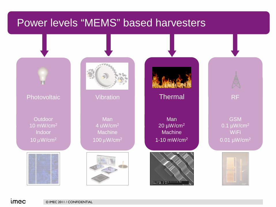
Man4 µW/cm2
Machine100 µW/cm2
WiFi0.01 µW/cm2
GSM0.1 µW/cm2
Machine1-10 mW/cm2
Man20 µW/cm2
Indoor10 µW/cm2
Outdoor10 mW/cm2
Power levels “MEMS” based harvesters*
ThermalPhotovoltaic RFVibration
*Vullers et al, Micropower Energy Harvesting, Solid-State Electronics 53 (7) Pgs 684-693, DOI: 10.1016/j.sse.2008.12.011

© IMEC 2011 / CONFIDENTIAL
Smart package (Perishables)
BAN
Smart buildings
APPLICATION FIELDS ENERGY HARVESTING
8
Predictive MaintenanceTPMS
RF
ThermalVibrational
ADVANCED ENERGY HARVESTING TECHNIQUES

© IMEC 2011 / CONFIDENTIAL 9
“NOT ENOUGH POWER IS
GENERATED”
you consume
too much !
you don’t generate enough !
And this largely explains the absence of killer applications
using energy harvesting

© IMEC 2011 / CONFIDENTIAL
THE ENERGY BALANCE
For a successful introduction of MEMS based Energy Harvester: The Power usage needs to be reduced
- Of the shelf components use ‘too’ much power- Power optimization needed towards ultra low power
Energy harvesters have to increase power output- Increase of harvesting efficiency- Increase of conversion efficiency -> Power Management is key!
Sensor
Read-out
DSP
Radio
Energy Harvester

© IMEC 2011 / CONFIDENTIAL
COST REDUCTION THROUGH MICRO-SYSTEM APPROACH
< 11
Size (or Cost)
Pow
er/u
nit
μW
mW
μm mm
Fine-machining
Micromachining

© IMEC 2011 / CONFIDENTIAL 12
SOMETHING ELSE IS (REALLY) WRONG WITH ENERGY HARVESTING TODAY: SCALING !
P.D. Mitcheson et al.; Proceedings of the IEEE, 96, No. 9, pp. 1 (2008)
Hmeas
norm EPPP ==
max
3161 3
4
ωρ VolY
PFOMAuo
measV =
± PRESENT
NEEDED (AT LEAST)
DISPROPORTIONAL SCALING WITH MINIATURIZATION (CASE OF VIBRATIONAL ENERGY HARVESTING)

© IMEC 2011 / CONFIDENTIAL
Advanced
energy harvest
ing
Man4 µW/cm2
Machine100 µW/cm2
WiFi0.01 µW/cm2
GSM0.1 µW/cm2
Machine1-10 mW/cm2
Man20 µW/cm2
Indoor10 µW/cm2
Outdoor10 mW/cm2
Power levels “MEMS” based harvesters
ThermalPhotovoltaic RFVibration
< 13
© IMEC 2011 / CONFIDENTIAL < 14
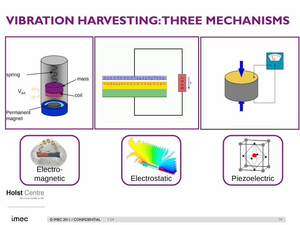
VIBRATION HARVESTING: THREE MECHANISMS
Permanent magnet
coil
springmass
Vout
ElectrostaticElectro-
magnetic Piezoelectric
14

© IMEC 2011 / CONFIDENTIAL
10-7
10-6
10-5
10-4
Out
put p
ower
(W)
3 4 5 6 7 8 91000
2
Frequency (Hz)
damp=0.016 damp=0.075 damp=0.133
Mechanical power generation: General principle
Possible range:10 -100 µW/cm2
Velocity damped resonator Maximum power conditions
Optimal transformation of mechanical energy into electricity occurs at the resonance frequency of the harvester!
Power
LX
m
LXmP
0
0
030
0
2
4)(
==
=
ωγς
ωω
X0: vibration amplitude L: system dimensionm: system massw0: resonance frequency
15

© IMEC 2011 / CONFIDENTIAL
INTELLIGENT TIRE
16
Radial mode
80km/h
• Intelligent tire: measurement of forces for improvement of active safety systems
• Resonant excitation ↔ high acceleration shock
• Shock → self resonance → ring down mode
80km/h → ~20 shocks/sec
300G shock → comparable to resonance at 1G for Q=300
Source: Pirelli tire company Ring down signal after shock (16G for 0.5ms) in matched load resistor
Road
Tyre
Forces
Friction coefficient between tire and road → improvement of active safety systems

© IMEC 2011 / CONFIDENTIAL
MEMS BASED PIEZOELECTRIC ENERGY HARVESTERS
17
Acceleration force
mass
beam
Piezo capacitor
Motion changes polarization
PZT: 40µ[email protected] (2.5g)
AlN: 60µW@572Hz (2.0g)
World Record output power
2007
2008
AlN power vs frequency
2009
Aiming for 500µW
AlN: 100µW@572Hz (1.0g)
2010 AlN: 225µW@929Hz (2.5g)
0
50
100
150
200
250
920 925 930 935 940
Pow
er [µ
W]
frequency [Hz]IEDM 2009: R. Elfrink et al., “First autonomous wireless sensor node powered by a vacuum-packaged piezoelectric MEMS energy harvester”

© IMEC 2011 / CONFIDENTIAL
PIEZOELECTRIC MATERIALS
SolGel
PZT • not IC fab compatible• SolGel
- limited thickness- low reproducibility- no topography allowed
• Sputtering- low deposition rate- composition control
sputtering
AlN • IC fab compatible • Sputtering
- high deposition rate- stoichiometric
Aluminum Nitride is good candidate for energy harvester
r
eFOMε
231=
e31 ~ -8 -12 C/m2
er ~ 1000tan d ~ 0.03 high lossZ ~ few kΩ < 0.1 Volt
e31 ~ -1.1 C/m2
er ~ 10tan d ~ 0.003 low lossZ ~ few MΩ few Volt
18

© IMEC 2011 / CONFIDENTIAL
WAFER LEVEL PACKAGE
• SU-8 on rolling wheel
• wafer at elevated temperature (~80C)
• topography is no issue
• vacuum inside package
0.0001
0.001
0.01
0.1
1
10
100
985 990 995 1000 1005 1010Frequency [Hz]
Pow
er [µ
W]
0.1 g atmospheric0.1 g vacuum1.0 g atmospheric1.0 g vacuum
Piezocapacitor
5 mm
19

© IMEC 2011 / CONFIDENTIAL 20
HARVESTER EFFECTIVENESS OF REPORTED DEVICES
P.D. Mitcheson et al.; Proceedings of the IEEE, 96, No. 9, pp. 1 (2008)
Hmeas
norm EPPP ==
max

© IMEC 2011 / CONFIDENTIAL
LEAKAGE OF WAFER LEVEL PACKAGE Reduction of power due to air leak into package ~50% power loss in half year time Hermetic wafer level package (long term vacuum to
minimize air damping)- Improvements of polymer based bonding- extra (metal) barriers- extra cavity - molding layer- Eutectic bonding
0.0
0.5
1.0
1.5
2.0
2.5
3.0
518 519 520 521 522 523 524 525Frequency [Hz]
Pow
er [µ
W]
t=0t=10 dayst=60 dayst=140 dayst=220 days
Piezocapacitor
SU-8 polymeric bond
air in leak
21
© IMEC 2011 / CONFIDENTIAL
Man4 µW/cm2
Machine100 µW/cm2
WiFi0.01 µW/cm2
GSM0.1 µW/cm2
Machine1-10 mW/cm2
Man20 µW/cm2
Indoor10 µW/cm2
Outdoor10 mW/cm2
Power levels “MEMS” based harvesters
ThermalPhotovoltaic RFVibration

© IMEC 2011 / CONFIDENTIAL 23
Seebeck effect (mechanism) Thermocouple structure
THERMO ELECTRIC ENERGY HARVESTING
Seebeck effect: Voc = Seebeck * DTHuman body DT ~ 1-3 K
Voltage output typically few mV

© IMEC 2011 / CONFIDENTIAL
MEMS BASED TEG ENERGY HARVESTERS; RESULTS
Planar 250 mV/K
In-plane 92 mV/K
World Record output voltage
2007
2008
Experimental result
2009
Aiming for 1V/K
High-topography 258 mV/K
High-topography thermocouple
Planar High-topographyIn-plane

© IMEC 2011 / CONFIDENTIAL
HISTORY OF MICROPOWERDEMONSTRATORS
• show feasibility of WATS systems for body area networks
• use of off-the-shelf components
• supporting research by investigate limits
• Includes new technology and circuit designs developed by IMEC
•Has resulted in Frost & Sullivan Award for ECG shirt

© IMEC 2011 / CONFIDENTIAL
Man4 µW/cm2
Machine100 µW/cm2
WiFi0.01 µW/cm2
GSM0.1 µW/cm2
Machine1-10 mW/cm2
Man20 µW/cm2
Indoor10 µW/cm2
Outdoor10 mW/cm2
Power levels “MEMS” based harvesters
ThermalPhotovoltaic RFVibration

© IMEC 2011 / CONFIDENTIAL
RF ENERGY TRANSFER INSTEAD : THREE MECHANISMS
•Inductive coupling•Close contact
27
Receiver coil
Vout
Transmit coil
Vin
Vin Vout
Transmit coil
Receiver coil
•Non-radiative coupling•Intermediate distances
•Radiative Coupling•Large distances
( ) 22
2
4 rGGPP RTT
inc πλ
=Power transfer: Friis equationλ: Wavelength usedGr, GT: Antenna Gain
PTPR; Power transmitted, received

© IMEC 2011 / CONFIDENTIAL
DCDC
boostconverter
battery
Rectenna Charger
For use in WSN, battery needs to be recharged:Minumum voltage is needed for IC = 0.2V→Vout determines distance→ Pinc determines charging time
RF BATTERY CHARGING
Vout, PoutPinc
28

© IMEC 2011 / CONFIDENTIAL
SMALL-SIZE RECTENNAAPPLICATIONSRF Battery charging
29
Charging 4.2V Li-Ion battery at 60 cm with EIRP=1.2W at 2.45GHz
Charging 2.9V Li-Ion battery at 166 cm with EIRP=1.2W at 2.45GHz

© IMEC 2011 / CONFIDENTIAL
< 30
Buck-boost converterVin-min=0.21V, Vout=3.0-4.2V
Theoretical distances for single-cell rectennas
More cells is larger distance

© IMEC 2011 / CONFIDENTIAL
SUMMARY
For autonomous wireless sensor system one needs:- Small low cost energy harvester- Power optimization of complete sensor system- Harvester + power management + energy storage
31
MEMS technology- Capable of 100µW/cm2
- Key for mass application
Still in research phase- Higher power output needed- Reliability and robustness

© IMEC 2011 / CONFIDENTIAL
THANK YOU FOR YOUR ATTENTION.