energy efficiency on conveyors - schneider electric expenses white paper on energy efficiency 1 for...
TRANSCRIPT

Make the most of your energy
For an optimal energy efficiency
of conveyors
January 2010/White paper
by Daniel Clénet,

Summary
Executive summary .................................................................................. I
Introduction ............................................................................................... III
Lowering expenses ................................................................................... 1
Moving fixed direct costs to variable direct costs .................................... 3
Operation analysis .............................................................................. 3
Validation of the operating mode ........................................................ 4
Energy savings ....................................................................................... 6
Application example............................................................................ 7
Fixed direct costs reduction .................................................................... 9
Real power, reactive power, apparent power ...................................... 9
Ways to limit the reactive power ......................................................... 9
Ways to decrease the real power ....................................................... 9
The Schneider Electric answer ................................................................. 10
The distributed controll offer ................................................................... 11
The Automation Function Blocs dedicated to machines ......................... 12
Conclusion ................................................................................................ 13
An optimized design ............................................................................... 13
Executive summary
In any human activity, handling cannot be ignored. Moving and transporting
goods belong to the daily life of each individual.
In the manufacturing and distribution activities, it is very often the bottleneck
where can focus many problems.
Indeed, handling has an influence on the machines productivity located
upstream and downstream, it has an impact on the work-in-progress and thus
presents a capital investment.
Frequently, handling have an effect on the quality of the product
With more than 2,5 million conveyors put in operation annually in the world,
conveying is an important energy consumer.
Smart choices allow to:
• increase the productivity by optimizing the operating modes,
• reduce the energy needs and thus limit the exploitation costs.
The judicious use of soft starters or variable speed dives allows to reduce
maintenance by limiting the electric and mechanical shocks
Making energy saving through a smart operating modes approach and the use of specific products.
White paper on Energy Efficiency I
For an optimal efficiency of conveyors

Introduction
Handling consists in moving a load from one place to another one without
alteration.
Several solutions can be used :
• lifting : the load is freely hanged to a lifting gear, operation is discontinuous.
Flexiblity is possible within some limits,
• belt conveyors or roller tables : the load is supported by the machine and is
carried by the movement of the belt or the rotation of the rollers. Operation is,
usually, continuous with very little flexibility,
• overhead conveyors with or without trolley : the load is hanged to a chain
moving continuously through the whole process. Operation is uninterrupted
with little flexibility if any,
• motorized overhead conveyors running on a common monorail with
shunting. Operation is discontinuous. Flexibility is possible within some limits.
• automatic guided vehicles (AGV’s) which follow a network layed in the
ground or a path controlled by a radio signal. Operation is discontinuous,
flexibility is virtually unlimited.
In spite of their apparent disparity, these solutions can be grouped in two
main categories :
1. manually operated conveyors ( transpallets, lifting trucks or lifting gear)
controlled by an operator,
2. automated devices in which we find the conveyors family.
The first solution is sometimes the unique possibility, for example loading
from a warehouse.
In manufacturing industries or distribution of products, the second solution
is essential, because it enables to reduce the handling costs. Furthermore
cycles of production are shortened and the risk of damage to packed
products is greatly reduced.
What follows is dedicated to belt and rollers conveyors and the goal of
this White Paper is to give ways to improve their efficiency.
White paper on Energy Efficiency II
For an optimal efficiency of conveyors

Introduction
To cover the majority of the needs, conveyors adopt three current
arrangements :
• linear conveyors to move loads between production units,
• transfer tables to change a course or to relocate a load from a conveyor to
another one,
• rotating tables which carry out a similar function while revloving the load.
Conveyors benefits are multiple :
• cost reduction of manual operations,
• loading and unloading are easy and safe,
• work-in-progress control and possibility of just in time production,
• limitation of idle time and intermediate stock between production units,
• pallets or products can be move to a large distance without damage.
The conveyors, however, present indirect costs, more or less related to their
use:
• power consumption,
• maintenance expenses,
• wearing parts replacement,
• investments and return on investments,
• insurances.
It is easily understandable that the choice of a conveyor and the manner of
controlling it will have noticeable influences on the production or distribution
costs. An in depth study must drive the choice of the solution.
These devices require motors, sensors and control devices adapted to the
function to be realized.
Regardless their specific use, they share number of essential functions such
as start and stop, devices for loading and unloading, operator interfaces,
safety functions to prevent accidents and, eventually, soft starters or variable
speed dives.
White paper on Energy Efficiency III
For an optimal efficiency of conveyors
Linear conveyor
Transfer table
Rotating table

Introduction
The traditional centralized PCL solution is gradually phasing out to totally
decentralized products controlling limited zones.
This architecture allows a greater flexibility, the autonomy of small production
units and an easier adaptation.
Decentralization also allows modularity and the rationalization of the
conveyors, thus a reduction of the design cost for the system supplier and
acquisition cost for the user.
These savings are partly linked to the use of common parts, reducing the
spare parts inventory and facilitating the maintenance operation.
The growing cost of energy, in particular for
fossil energies, (cf graphs hereafter from the
Observatory of Energy according to Eurostat -
January 2007) imposes new strategies for the use
of conveyors.
It becomes interesting to shut down a conveyor or
use variable speed to realize savings.
White paper on Energy Efficiency IV
For an optimal efficiency of conveyors
Cost of electricity (without VAT) for industrial use
Cost of natural gaz (without VAT) for industrial use
Belgium Germany Spain France Italy UK
Belgium Germany Spain France Italy UK

For an optimal energy efficiency of conveyors

Lowering expenses
White paper on Energy Efficiency 1
For an optimal efficiency of conveyors
Savings in a major consideration when designing a conveying line. Due to
the large number of conveyors, cost can easily be unacceptable and the
return on investment may be problematic
The following table gives the usual cost family
• Cell N°1 : Direct and variable costs. The
resources listed in this cell are exclusively used
for the products; these expenditures are directly
charged to the products.
• Cell N°2 : Direct and constant expenses.
They can directly be affected to the cost of the
products. When their amount is significant, these
expenses are separated from the fixed common
charges and used in an additional stage during
the calculation of the partial costs. What has the
advantage of refining the analysis and to have a
correct idea of the contribution of each product to
cover the common fixed charges.
• Cell N°3 : Indirect and variable costs. In fact
these costs are difficult to evaluate and require
a complex process and an in depth analysis.
Energy efficiency has the most impact.on these
costs
• Cell N°4 :Indirect and fixed costs. They are
generally incompressible. They are managed in
a different way according to the selected method
of analysis.
Ways to progress exist for each cell. Sometimes
it is mandatory to reconsider the operation of the
production line.
The saving impossible to circumvent consists to
move the fixed costs to variable costs (2 towards
1). In other words allowing what is just necessary
for the operation. This can be done by modifying
the operating modes of the equipment, for
example make it running only when required.
Ideally, it is desirable to switch direct costs into
indirect variable costs (1 and 4 towards 3) by
subcontracting some work or eliminating the
superfluous load.
Variable expenses Constant expenses
Direct costs
Indirect costs
2Rental , dedicated equipment @
amortizing; dedicated insurances,
Commercial and distribution costs, @
Other specific costs @
3 4
1Raw products, goods linked to the @
products, components
Labor @
Sub contracting @
Power consumption in the @workshops,
Workshop expenditures @
Miscellaneous supplies... … @
Investments @
Overheads @ (research and development; public relationship, accounting, audits, lawyers, patents)

Lowering expenses
White paper on Energy Efficiency 2
For an optimal efficiency of conveyors
In the real world, one can estimate that nearly
60% of the conveyors, loaded or unloaded,
are running continuously. The resuslt is afixed
energy consumption.
An analysis of the relations between the power
consumption of a convoying line and the the
tasks which it carries, defines 4 modes of
operation:
1.Work in progress : the line moves loads. In this
mode, control and actuators are energized.
2. standby : the machine is running while waiting
for loads, because the preceding or following
machine is not ready. Energy is wasted,
3. stop : an operator places the conveying line
in this mode when the production is stopped
(defect, factory shutdown…) The machine is then
in a safety mode (actuators should not be able
to restart) and an automatic restart is impossible.
Parts of control are off (pre-actuators) but some
remain connected to the power supply (PLC’s,
MMI, I/O’s…)
4. oFF : the conveying line is inert (maintenance,
disjunction…).
The three goals in order to reduce the financial
cost can be summarized as follows:
1.transFormation oF the Fixed direct costs in
variable direct costs (21)
Modification of the operating modes of the
mechanical equipment which is started only
when required.
2. loWering the Fixed costs (2)
Elimination of reactive power
3.loWering the Fixed indirect costs (4)
Install soft starters or variable speed drives to
encrease the lifetime of the equipment by limiting
the mechanical shock due to direct on line
starting.

Lowering expenses
White paper on Energy Efficiency 3
For an optimal efficiency of conveyors
Moving fixed direct costs to variable direct costs
OPeratiOn analyzis
The first step for energy efficiency consists of
analyzing the operating modes of the conveyor
and, by extension all the line.
This analyse will evaluate the duration and the
frequency of the idle time..
Diagram 1 represents a basic conveyor equipped
with:
• an AC motor and its reducer,
• an upstream sensor (Inputsensor)
• a downstream sensor (Ouputsensor).
We represented a single load, but in the real
world, this load will be generally a whole of
elements distributed in a more or less uniform
way on the conveyor.
We are going to examine the constraint imposed
on a conveyor started at the approach of the
load.
The velocity of the upstream conveyor is
said to be the same as the studied conveyor
(Conveyorvelocity).
The position of the Inputsensor relative to the
loading zone of the conveyor (Sensordistance) must
cover two constraints:
• Sensordistance < Loadlength
(where Loadlength is the size of the load)
• Sensordistance ≥ Conveyorvelocity x Startingtime
(where Startingtime is the time needed to start the
conveyor till its nominal speed (Conveyorvelocity) is
obtained.
Thus:
Respecting this physical constraint allows the
best optimization as well from the point of view of
energy efficiency as transfer time of the load.
Load
Downstreamconveyor
Reducer
AC motorDiagram 1
Sensordistance
Inputsensor
Upstreamconveyor
Outputsensor
Conveyorlength
Conveyorvelocity
Loadlength

Lowering expenses
White paper on Energy Efficiency 4
For an optimal efficiency of conveyors
ValidatiOn Of the OPerating mOde
In this second step, we answer the question :
Is it wise to keep the conveyor running if
unloaded?
The above diagram shows the evolution of
powers and energy consumptions according to
the status of the conveyor.
In this diagram, the conveyor is energized when
the load is detected and runs unloaded before its
introduction. The conveyor is stopped when the
load has been unloaded.
Légend :
Tbetweenparts : time between 2 consecutiveloads on
the conveyor.
Carrythroughtime : time needed to move the load
from input to output
Operatingtime : time elapsed from starting to
stoppage of the conveyor
Startingtime : time needed to obtain nominal
speed,
Startingpower: real power needed to start the
conveyor,
Startingenergy = Startingpower x Startingtime
Carrythroughenergy : energy needed to carry the
load from input to output
Unloadedpower : real power needed
to move an unloaded conveyor,
Unloadedenergy : energy needed to
move an unloaded conveyor,
The conveyor will be deenergized
according to the time elapsed
between two consecutive parts.
Conveyor parameters must be
taken into account (operating time,
electrical values).
The sufficient condition to stop the
conveyor while making energy saving is:
According to the type of load and specific
mechanical constraints, it can be necessary to
encrease the running time (Operatingtime) in order
to make sure that the load is correctly transfered
onto the downstream conveyor That is done by
adding a time delay after the activation of the
Ouputsensor as represented on the diagram below.
Part is loaded
TbetweenpartsPower
Carrythroughtime
Operatingtime
Startingtime
Startingpower
CarrythroughenergyUnloadedpower
StartingenergyStartingenergyUnloadedenergy1
Inputsensor
OnPart is unloaded Inputsensor
On
Part is loaded
Unloadedenergy1
nsor
r
r
PowerStartingpowe
Unloadedpowe
StartingenergyStartingenergy
Inputse
On
Carrythroughenergy
Part is unloaded Inputsensor
On
Unloadedenergy2
Tbetweenparts
Carrythroughtime
Operatingtime
Startingtime
EnOperatingtime
Tbetween
Carrythroughtime
Operatingtime
Startingtime
EnOperatingtime

Lowering expenses
White paper on Energy Efficiency 5
For an optimal efficiency of conveyors
Légend :
EnOperatingtime : time elapsed from starting to
stoppage of the conveyor with an additional time
delay
Thus the equation becomes:
The time delay in oder ti increase the running
time can be empirical or calculated according
to the length of the load and the position
of Ouputsensor (which is Inputsensor for the
downstream conveyor).
It is possible to chose a value for the time delay
considering an uniforme distribution of the load.
Thus, running time will be:
At last, to make sure of the relevance of the
operating modes modification, the right thing to
do is to check the following equation: :
If, and only if, this condition is true, the
modification of the operating mode will generate
an energy saving without degrading the
performance of the conveyor.
If the above condition is false, it is strongly
recommended to keep the conveyor running
continuously.
The energy consumption is:

energy saVings
Energy saving corresponds to the difference
in energies between the continuous operating
process (diagram below) and the operating
process of the previous diagram.
When running continuously, the power
consumption is :
After optimizing the operating mode, saving is :
Where:
Saving relative to real power is :
We can also estimate the reactive power saving.
This reactive power is needed to produce
the magnetization of the motor and can be
considered constant whatever the load of the
motor
So:
On all diagrams we can see at a
first glance that if the starting time
is short, the starting energy can be
neglected. This makes calculations
easier to complete.
The Startingtime term thus
disappears from all equations.
Lowering expenses
White paper on Energy Efficiency 6
For an optimal efficiency of conveyors
r
r
PowerStartingpowe
Unloadedpowe
Part is loaded
Unloadedenergy1
nsorInputse
On
Unloadedenergy0
Tbetweenparts
Carrythroughtime
Operatingtime
Startingtime
EnOperatingtime
Carrythroughenergy
Part is unloaded Inputsensor
On
Unloadedenergy2 Unloadedenergy3
Lowering expenses
White paper on Energy Efficiency 7
For an optimal efficiency of conveyors
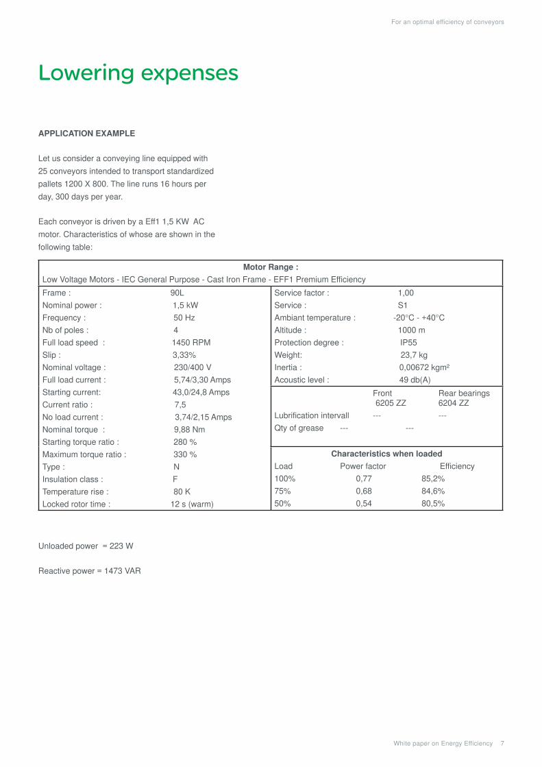
aPPliCatiOn examPle
Let us consider a conveying line equipped with
25 conveyors intended to transport standardized
pallets 1200 X 800. The line runs 16 hours per
day, 300 days per year.
Each conveyor is driven by a Eff1 1,5 KW AC
motor. Characteristics of whose are shown in the
following table:
Unloaded power = 223 W
Reactive power = 1473 VAR
motor range :
Low Voltage Motors - IEC General Purpose - Cast Iron Frame - EFF1 Premium Efficiency
Frame : 90L
Nominal power : 1,5 kW
Frequency : 50 Hz
Nb of poles : 4
Full load speed : 1450 RPM
Slip : 3,33%
Nominal voltage : 230/400 V
Full load current : 5,74/3,30 Amps
Starting current: 43,0/24,8 Amps
Current ratio : 7,5
No load current : 3,74/2,15 Amps
Nominal torque : 9,88 Nm
Starting torque ratio : 280 %
Maximum torque ratio : 330 %
Type : N
Insulation class : F
Temperature rise : 80 K
Locked rotor time : 12 s (warm)
Service factor : 1,00
Service : S1
Ambiant temperature : -20°C - +40°C
Altitude : 1000 m
Protection degree : IP55
Weight: 23,7 kg
Inertia : 0,00672 kgm²
Acoustic level : 49 db(A)
Front Rear bearings 6205 ZZ 6204 ZZ
Lubrification intervall --- ---
Qty of grease --- ---
Characteristics when loaded
Load Power factor Efficiency
100% 0,77 85,2%
75% 0,68 84,6%
50% 0,54 80,5%

Lowering expenses
White paper on Energy Efficiency 8
For an optimal efficiency of conveyors
The mechanical characteristics for each
conveyor are shown below :
For this example, we will neglect the energy
used to start the conveyor.
Calculation of the optimal distance for the
Inputsensor (mm):
Let us choose Inputdistance = 100 mm
The running distance of the pallet is thus :
2414 + 100 = 2514 mm and its running time is
2514/300 seconds rounded to 8,4 s
Time between two pallets must be :
Let us select 11s an idle time between two
pallets and encrease the running time by 9s.
The simplified method used for the calculation of
energy saving gives for a conveyor and a pallet :
Consequently for the line of 25 conveyors
running during 1 year long (327 loads per hour) :
saving for one year exceeds 18% of the
power consumption.
Charge
Sensordistance Conveyorlength
Inputsensor
LoadlengthConveyorvelocity
= 2414mm
= 0,3m/s= 1200mm
Diagram 7
Output sensor

Lowering expenses
White paper on Energy Efficiency 9
For an optimal efficiency of conveyors
Fixed direct costs reduction
real (aCtiVe) POWer, reaCtiVe POWer,
aPParent POWer
Any electric machine using AC voltage (motor,
transformer) uses two forms of powers: real
power (active power) and reactive power.
Real energy (kWh) is transformed completely
into mechanical work and losses (heat).
Reactive Power (kVARh), i.e. magnetizing
energy is almost a constant, independent of the
load.
Electrical Uilities charge customer for the real
power.
Howether, in an electric power system, a load
with low power factor draws more current
than a load with a high power factor for the
same amount of useful power transferred. The
higher currents increase the energy lost in the
distribution system, and require larger wires and
other equipment.
Because of the costs of larger equipment and
wasted energy, electrical utilities will usually
charge a higher cost to industrial or commercial
customers where there is a low power factor.
The invoice for reactive power is voluntarily
dissuasive in order to encourage the users to
install compensation systems.
Ways tO limit the reaCtiVe POWer
The simple fact of reducing the reactive power
allows to generate savings, large enough to
justify the installation of compensation systems.
There are several devices:
• capacitor banks,
• variable speed drives.
However, a variable speed drive must be
equipped with harmonic filters or, best, an active
front end.
If not, it will introduce harmonics contents in the
input current and a noticeable increase of the
apparent power. The cost of the solution may
exceed the expected savings.
If savings in the only objective, installation of this
solution is not, most of the time, cost effective.
Ways tO deCrease the real POWer
On the other hand, the use of variable speed
drives allow to :
• reduce the size of the AC motors,
• simplify the kinematic chain,
• adapt the speed of the conveyors to the
production needs
• reduce the starting shocks and avoid damaging
the loads.
Resulting savings make it possible to quickly
amortize the cost of the equipment.
White paper on Energy Efficiency 10
For an optimal efficiency of conveyors
To feed these needs, Schneider Electric has
developed a coherent offer based on the
SoMachine concept which allows designing an
automatism system in a single environment.
The PLC, the variable speed drive or the motion
control as well as the dialogue are associated
with blocks function, fully tested, validated and
documented . Without sacrificing performance,
flexibility and price, that gives to the machine
manufacturer the certainty of :
• easily solve the critical phases of the system,
• built equipment in conformity with laws and the
requirements of the various countries,
• ensure the safety of the machine and the
workers,
• simplify the integration of the different
components.
Schneider Electric split its offer for Conveying
applications in three categories of machines :
• simple machines that one can define as a
single conveyor or an association of several
identical conveyors,
• flexible machines which are association of
various conveyors for example two lines of
parallel conveyors and a transfer table,
• systems where flexible machines are integrated
into a complex unit where we find other PLC’s, a
SCADA or a production control.
These three preceding categories share a certain
number of needs :
• mechanical part,
• motorization,
• AC motors control, either direct on line starters,
soft starters, or variable speed drives,
• automation and dialogue,
• facility of maintenance,
• control of the ownership costs.
The principal requirement for the simple
machines is easy commissioning and a low price.
The requirements for the flexible machines
will be a modular architecture, an increased
productivity and needs for traceability of the
transported products. For the system, the
additional requirements will be the possibility of
integration to the corporate network and as well
as an improved dialogue.
Strong from this analysis, Schneider Electric
proposes:
• automatism architectures
• dedicated AFB’s
conveyor,
turn table,
tranfer table,
• motor starters installed in remote enclosures for
distributed control..
The Schneider Electric answer
White paper on Energy Efficiency 11
For an optimal efficiency of conveyors
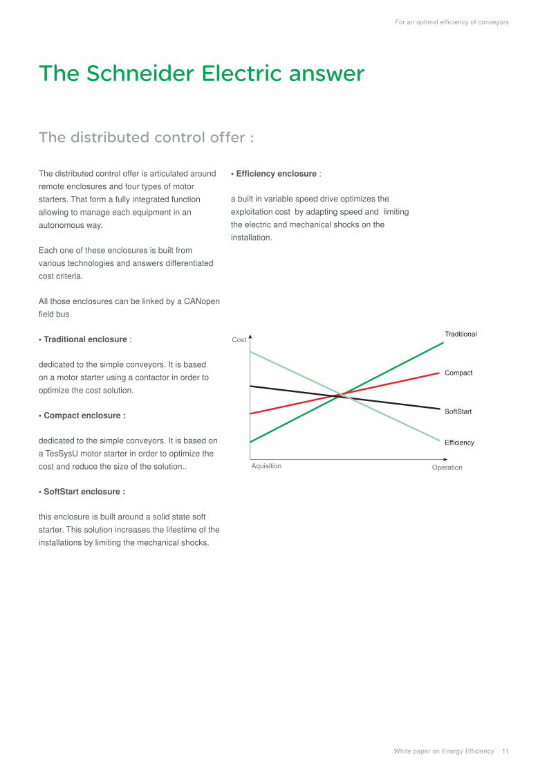
The distributed control offer :
The distributed control offer is articulated around
remote enclosures and four types of motor
starters. That form a fully integrated function
allowing to manage each equipment in an
autonomous way.
Each one of these enclosures is built from
various technologies and answers differentiated
cost criteria.
All those enclosures can be linked by a CANopen
field bus
• Traditional enclosure :
dedicated to the simple conveyors. It is based
on a motor starter using a contactor in order to
optimize the cost solution.
• Compact enclosure :
dedicated to the simple conveyors. It is based on
a TesSysU motor starter in order to optimize the
cost and reduce the size of the solution..
• SoftStart enclosure :
this enclosure is built around a solid state soft
starter. This solution increases the lifestime of the
installations by limiting the mechanical shocks.
• Efficiency enclosure :
a built in variable speed drive optimizes the
exploitation cost by adapting speed and limiting
the electric and mechanical shocks on the
installation.
The Schneider Electric answer
Cost
Aquisition Operation
Traditional
Compact
SoftStart
Efficiency
The Schneider Electric answer
White paper on Energy Efficiency 12
For an optimal efficiency of conveyors
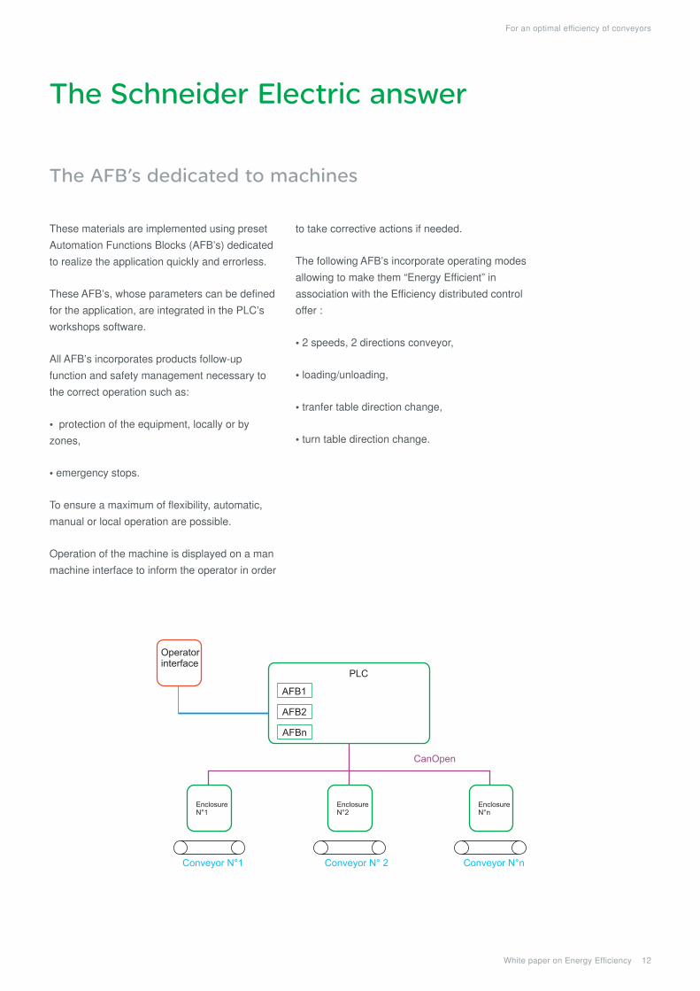
The AFB’s dedicated to machines
These materials are implemented using preset
Automation Functions Blocks (AFB’s) dedicated
to realize the application quickly and errorless.
These AFB’s, whose parameters can be defined
for the application, are integrated in the PLC’s
workshops software.
All AFB’s incorporates products follow-up
function and safety management necessary to
the correct operation such as:
• protection of the equipment, locally or by
zones,
• emergency stops.
To ensure a maximum of flexibility, automatic,
manual or local operation are possible.
Operation of the machine is displayed on a man
machine interface to inform the operator in order
to take corrective actions if needed.
The following AFB’s incorporate operating modes
allowing to make them “Energy Efficient” in
association with the Efficiency distributed control
offer :
• 2 speeds, 2 directions conveyor,
• loading/unloading,
• tranfer table direction change,
• turn table direction change.
PLC
AFB1
AFB2
AFBn
EnclosureN°1
CanOpen
Conveyor N°1 Conveyor N° 2 Conveyor N°n
Operatorinterface
EnclosureN°2
EnclosureN°n

Conclusion
White paper on Energy Efficiency 13
For an optimal efficiency of conveyors
An optimized design
The solutions are based on the CANopen field bus which leaves possibility
to interface the equipment with third party products with the greatest facility.
Remote control gives flexibility and upgrading capabilities without modifying
the whole installation.
The AFB’s, fully documented, are preset and usable immediately without
requiring a particular adaptation.
Standard architectures give the insurance for an optimum result in a
minimum designing time.
The use of soft starters makes it possible to reduce the mechanical
constraints and to start a line without risk of damage of fragile transported
products.
The reduction in these constraints enable to stop and restart a conveyor
without impacting its lifespan, thus allowing a substantial reduction of power
consumption.
The choice of the variable speed drive (VSD), while adjusting the speed,
allows energy savings.
VSD drive allows, under certain circumstances, to improve the power-factor
of the electric motors which, in this case, becomes close to unity at any
speed.
The Schneider Electric innovating approach allows the designer as well as
the user to have an efficient and economical solution.
A wise choice of operating mode, the use of energy compensation, soft staters and variable speed drive are smart solutions to make significant savings on a conveying line.

schneider electric sa
35 rue Joseph Monier F-92500 Rueil Malmaison - France Phone: + 33 (0) 1 41 29 70 00 Fax: + 33 (0) 1 41 29 71 00 http://www.schneider-electric.com
Document Number WP20100601EN
© 2
010
Sch
neid
er E
lect
ric. A
ll rig
hts
rese
rved
.
01/2010
This document has beenprinted on recycled paper