energy deposition in q0 elena wildner 19/04/07. strategy 1. define a tas to protect the q0 2....
TRANSCRIPT

Energy Energy deposition in Q0 deposition in Q0
Elena Wildner
19/04/0719/04/07
StrategyStrategy
1. Define a TAS to protect the Q02. Optics: *= 0.25m3. Calculate, with some optimization of the
TAS layout, the heat deposition in the Q0 magnets
4. Check experiment
Point 4 still to be treated

Layout of scenario Layout of scenario
Q01
13 m 3 m
IP Tas
3.0 m
Q02
3.5 m
9 m
IP

Modeling the QuadsModeling the Quads
FeHe
Cu
4.5
Fe
10.5
28.0
30.0
16.5
P. Limon, G. KirbyP. Limon, G. Kirby

Define the efficient TAS openingDefine the efficient TAS opening
mmmmdD 6.12)3(2)5.725.9(1.1min
Beam sep.
Spurious disp. orbit
Beam size
Mech. tol. and alignment
Depends on
beating orbit
L= 10 E 35

-dependence of opening -dependence of opening
*IP TAS opening for small beta function:
more debris are intercepted by shield
TAS opening for large beta function: less debris are intercepted by shield
Debris cones
Beta function
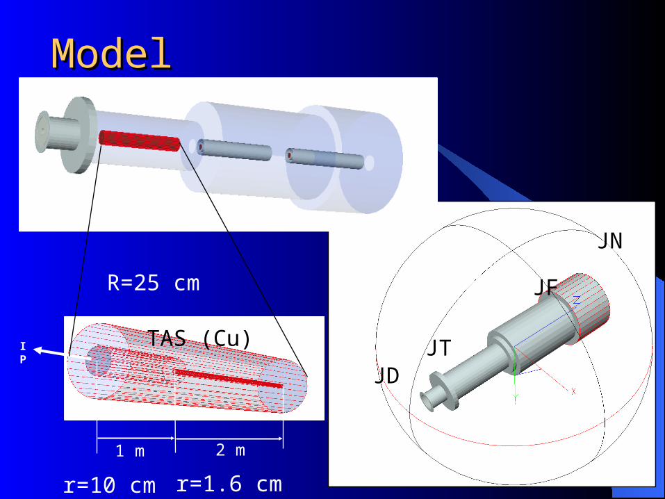
ModelModel
JT
JF
JN
JD
IP
TAS (Cu)
1 m 2 m
r=10 cm r=1.6 cm
R=25 cm
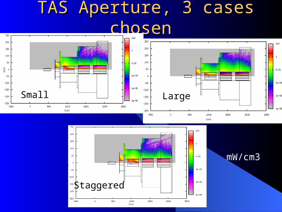
TAS Aperture, 3 cases chosen TAS Aperture, 3 cases chosen
Small Large
Staggered
mW/cm3
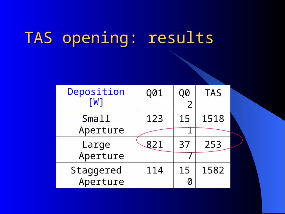
TAS opening: resultsTAS opening: results
Deposition [W] Q01 Q02 TAS
Small Aperture 123 151 1518
Large Aperture 821 377 253
Staggered Aperture
114 150 1582
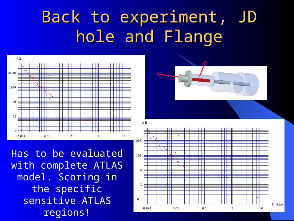
Back to experiment, JD hole Back to experiment, JD hole and Flangeand Flange
0.001 0.01 0.1 1 10Energy1
10
100
1000
10000
All
0.001 0.01 0.1 1 10Energy
0.1
1
10
100
1000
All
Has to be evaluated with complete ATLAS model.
Scoring in the specific sensitive ATLAS regions!
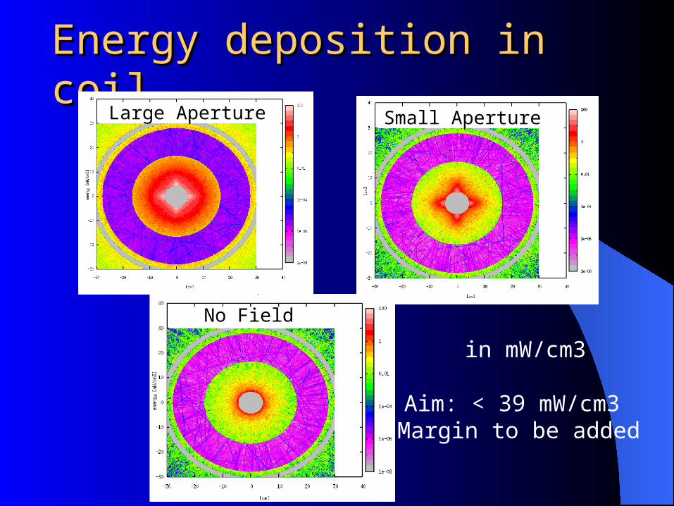
Energy deposition in coilEnergy deposition in coilLarge Aperture Small Aperture
No Field
in mW/cm3
Aim: < 39 mW/cm3 Margin to be added
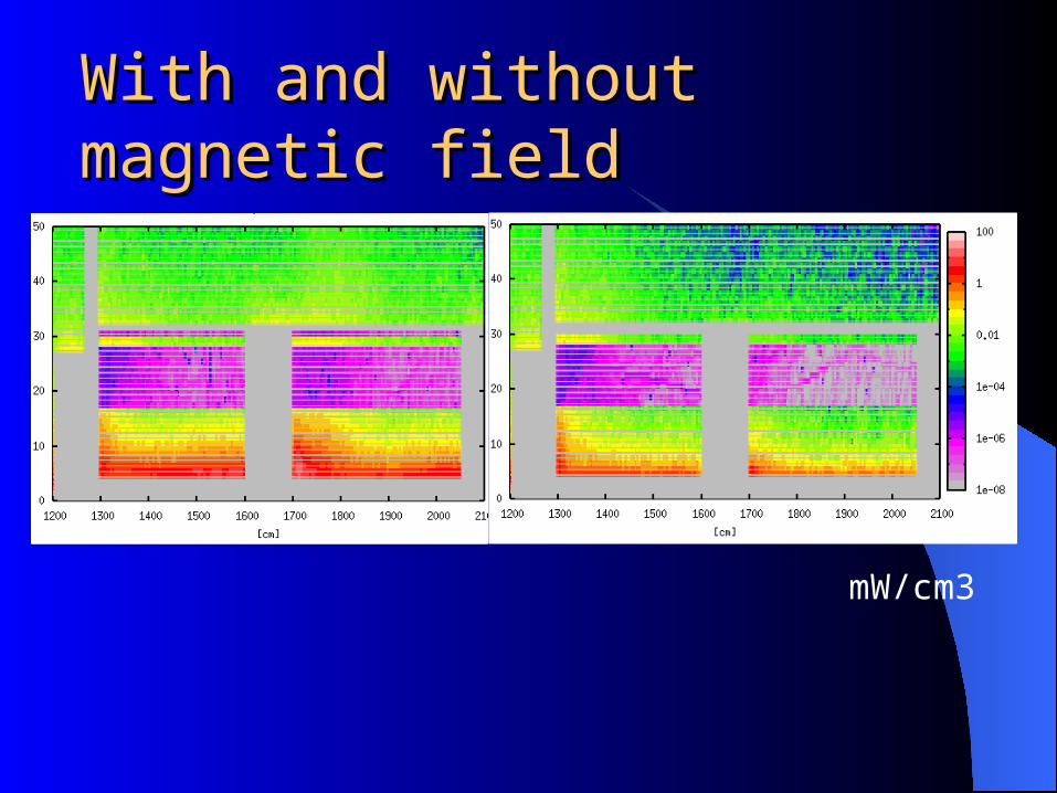
With and without magnetic fieldWith and without magnetic field
mW/cm3
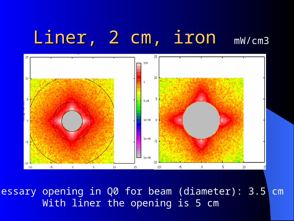
Liner, 2 cm, iron Liner, 2 cm, iron mW/cm3
Necessary opening in Q0 for beam (diameter): 3.5 cmWith liner the opening is 5 cm

The TAS ApertureThe TAS Aperture
Power Deposition [W] Q01 Q02 TAS
Staggered Aperture (liner) 198 (100) 331 (150) 1530
Staggered Aperture, liner & solenoid field
197 330 1550
Staggered Aperture, no liner
114 150 1582

Without and with LinerWithout and with Liner
mW/cm3

Power in the cables: Q01Power in the cables: Q01
0 100 200 300 400 500 600
10
20
30
40
50InnerCable:Blue, Next:Red, Yellow, Green
0 100 200 300 400 500 600
10
20
30
40
50
0 100 200 300 400 500 600
10
20
30
40
50
0 100 200 300 400 500 600
10
20
30
40
50
Binning as cable: 4 radial bins (1 per cable): 15 mm 600 azimuthal bins: ~ 1 mm wide
The longitudinal bins are 10 cm long.
mW/cm3
5 x 300 particles !

Power in the cables: Q02Power in the cables: Q02
mW/cm3
0 100 200 300 400 500 600
10
20
30
40
50InnerCable:Blue, Next:Red, Yellow, Green
0 100 200 300 400 500 600
10
20
30
40
50
0 100 200 300 400 500 600
10
20
30
40
50
0 100 200 300 400 500 600
10
20
30
40
50
Binning as cable: 4 radial bins (1 per cable): 15 mm 600 azimuthal bins: ~ 1 mm wide
The longitudinal bins are 10 cm long.
10-20 cm
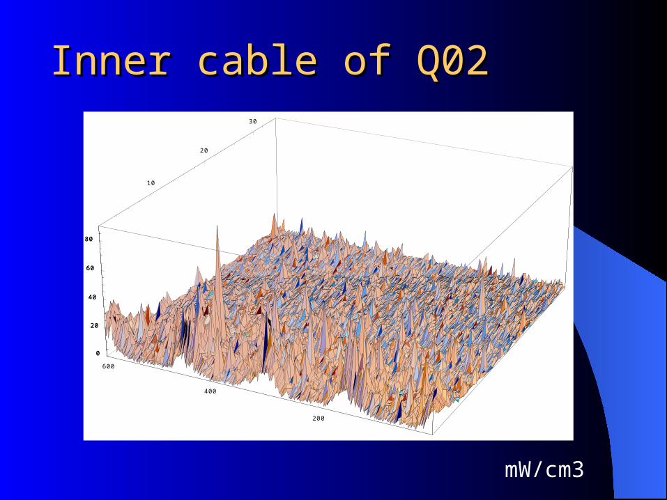
Inner cable of Q02Inner cable of Q02
10
20
30
200
400
600
0
20
40
60
80
0
20
40
60
80
mW/cm3

FLUKA model of ATLAS: JTFLUKA model of ATLAS: JT
TAS to be inserted

Summary 1Summary 1Staggered TAS with a liner in the Q0 seems to
be a reasonable solution: – magnet developers can continue
Power deposition in the coil will be below 39 mW/cm3 (limit for quench) with some optimization. Margin needed.
Solenoid field: no significant impactCrossing angle: no significant impactTungsten TAS: no significant impact
Summary 2Summary 2
Shorter TAS (1 m) put at same distance (back edge) and 2 m closer to IP with adapted opening: more heat in magnet
After optimization, more particles in FLUKA runs for better statistics necessary
ATLAS model to be run with their scoring in their regions of interest. Compare:
Model without new TASModel with new TAS