energy conservation building code for residential
TRANSCRIPT
Energy Conservation Building Code for Residential Buildings (Part I: Building Envelope Design)
Bureau of Energy Efficiency (BEE) i
CONTENTS
CONTENTS ................................................................................................................................................................................ I
LIST OF TABLES ...................................................................................................................................................................... II
LIST OF FIGURES ................................................................................................................................................................... III
CHAPTER 1. BACKGROUND .............................................................................................................................................. 1
CHAPTER 2. SCOPE ............................................................................................................................................................ 3
CHAPTER 3. CODE PROVISIONS ....................................................................................................................................... 4
3.1 RESIDENTIAL ENVELOPE TRANSMITTANCE VALUE (RETV) FOR BUILDING ENVELOPE (EXCEPT ROOF) FOR FOUR CLIMATE
ZONES, VIZ. COMPOSITE CLIMATE, HOT-DRY CLIMATE, WARM-HUMID CLIMATE AND TEMPERATE CLIMATE ................................... 4 3.2 THERMAL TRANSMITTANCE OF BUILDING ENVELOPE (EXCEPT ROOF) FOR COLD CLIMATE (UENVELOPE,COLD) .............................. 5 3.3 THERMAL TRANSMITTANCE OF ROOF (UROOF) ................................................................................................................... 6 3.4 OPENABLE WINDOW-TO-FLOOR AREA RATIO (WFROP) ..................................................................................................... 6 3.5 VISIBLE LIGHT TRANSMITTANCE (VLT) ........................................................................................................................... 7
CHAPTER 4. CODE COMPLIANCE ..................................................................................................................................... 8
4.1 COMPOSITE CLIMATE, HOT-DRY CLIMATE, WARM-HUMID CLIMATE AND TEMPERATE CLIMATE ........................................... 8 4.2 COLD CLIMATE ............................................................................................................................................................. 8
ANNEXURE 1. CALCULATION OF THERMAL TRANSMITTANCE (U VALUE) OF ROOF AND WALL ...................... 10
A1.1 CALCULATION PROCEDURE FOR U VALUE OF WALL AND ROOF .................................................................................. 11 A1.2 CALCULATION PROCEDURE FOR U VALUE OF FENESTRATION (NON-OPAQUE BUILDING ENVELOPE COMPONENT) .......... 14
ANNEXURE 2. CALCULATION OF EQUIVALENT SHGC .............................................................................................. 15
ANNEXURE 3. CALCULATION OF WINDOW-TO-WALL RATIO (WWR) ...................................................................... 17
ANNEXURE 4. CALCULATION OF WINDOW OPERABLE AREA TO FLOOR AREA RATIO (WFROP) ....................... 18
ANNEXURE 5. EXAMPLES OF CODE COMPLIANCE ................................................................................................... 19
ANNEXURE 6. CLIMATIC ZONE & CLASSIFICATION OF CITIES ................................................................................ 28
ANNEXURE 7. TERMINOLOGY AND DEFINITIONS ...................................................................................................... 30
COMMITTEES AND WORKING GROUPS ............................................................................................................................. 32
STEERING COMMITTEE (PARTICIPANTS) ................................................................................................................................. 32 TECHNICAL COMMITTEE (PARTICIPANTS) ................................................................................................................................ 33 DEVELOPMENT TEAM ............................................................................................................................................................ 34
Energy Conservation Building Code for Residential Buildings (Part I: Building Envelope Design)
Bureau of Energy Efficiency (BEE) ii
LIST OF TABLES
Table 1: Coefficients for RETV formula ..................................................................................................................................... 5 Table 2: Minimum requirement of window-to-floor area ratio, WFRop ........................................................................................ 6 Table 3: Minimum Visible Light Transmittance (VLT) requirement ............................................................................................ 7 Table 4: U value of typical wall ................................................................................................................................................ 10 Table 5: U value of typical roof ................................................................................................................................................ 10 Table 6: Thermal Properties of Building and Insulating Materials ............................................................................................ 12 Table 7: Thermal resistance of air gaps ................................................................................................................................... 14 Table 8: Defaults for Unrated Vertical Fenestration (Overall Assembly including the Sash and Frame) ................................. 14 Table 9: Coefficients of Shading Equivalent Factors for Latitudes greater than or equal to 15ºN ........................................... 16 Table 10: Coefficients of Shading Equivalent Factors for Latitudes less than 15ºN ................................................................ 16 Table 11: Default openable area to opening area ratio............................................................................................................ 18 Table 12: Details of exposed door, windows and ventilators ................................................................................................... 19 Table 13: Details of construction material ................................................................................................................................ 19 Table 14: Wall areas of the building ......................................................................................................................................... 20 Table 15: Openable area calculation ....................................................................................................................................... 20 Table 16: Calculation of window-to-wall ratio ........................................................................................................................... 21 Table 17: Roof construction details .......................................................................................................................................... 22 Table 18: Equivalent SHGC calculation ................................................................................................................................... 23 Table 19: Details of exposed door, windows and ventilators ................................................................................................... 25 Table 20: Details of construction material ................................................................................................................................ 25 Table 21: Wall areas of the building ......................................................................................................................................... 25 Table 22: Calculation of openable areas ................................................................................................................................. 26 Table 23: Calculation of window-to-wall ratio ........................................................................................................................... 26 Table 24: Climate Zone for Major Indian Cities ........................................................................................................................ 29
Energy Conservation Building Code for Residential Buildings (Part I: Building Envelope Design)
Bureau of Energy Efficiency (BEE) iii
LIST OF FIGURES
Figure 1: Projection factor ........................................................................................................................................................ 15 Figure 2: Layout plan of the project ......................................................................................................................................... 19 Figure 3: Plan of a typical DU .................................................................................................................................................. 19 Figure 4: Building for compliance check on the layout of project ............................................................................................. 20 Figure 5: Climate zone map of India ........................................................................................................................................ 28

Energy Conservation Building Code for Residential Buildings (Part I: Building Envelope Design)
Bureau of Energy Efficiency (BEE) 1
Chapter 1. Background
1.1 India’s Nationally Determined Contributions commit to reducing emission intensity of its
GDP to 35% below 2005 levels by 2030. Any effort to achieve this target is contingent upon
the increase in efficiency of energy use across all sectors, especially in the building sector.
The building sector in India consumes over 30% of the total electricity consumed in the country
annually and is second only to the industrial sector as the largest emitter of greenhouse gases.
Building energy codes for new buildings are an important regulatory measure for ushering
energy efficiency in the building sector. They are particularly relevant for countries like India
where the building stock is rising rapidly. The commercial sector among buildings has been
addressed by the Energy Conservation Building Code (ECBC) for Commercial Buildings. The
first version of ECBC was released in 2007 and a revised version was issued in June 2017.
Given the current and anticipated rapid growth in residential building stock across India and
the consequent opportunities as well as the necessity for energy conservation in this sector
the Energy Conservation Code for Residential Buildings is being established by the Ministry
of Power.
1.2 Out of the total electricity consumed in the building sector, around 75% is used in the
residential buildings. The gross electricity consumption in residential buildings has been rising
sharply – it was around 50 TWh in 1995 and has increased by more than four times in next 20
years and was around 220 TWh in 2015. Projections show it rising to anywhere between 600
-900 TWh by 2030. Among various reasons, increased use of decentralized room based air
conditioning units in homes is one of the important reasons contributing to this rapid increase
in the electricity use in residential buildings. This increasing demand for air-conditioned
thermal comfort, that will continue its exponential growth with improvement in household
incomes, will become the most contributor to GHG emissions nation-wide. This calls for an
urgent and immediate energy conserving action plan.
1.3 Building envelope consists of the walls, roof, windows and fenestration. Major parts of
India have hot and humid climates. Research presented in the National Building Code (NBC)
and Handbook on Functional Requirement for Buildings (SP: 41), both published by the
Bureau of Indian Standards, has established a direct correlation between the design of
building envelop and the heat gains from the building envelope. Heat gains in turn determine
the indoor temperatures, thermal comfort and sensible cooling demand. Current designs of
building envelope are often not guided by considerations of heat gain and resultant cooling
requirement to achieve indoor thermal comfort. It is seen current practices of residential
buildings design and construction show a large variation in heat gains and hence in the
sensible cooling demand. The ratio between the minimum to maximum sensible cooling
demand can vary by as much as 1:4.
1.4 The production of residential building stock in urban areas is shifting quickly toward multi-
storey residential buildings from the earlier mode of building individual homes. It is expected
that, with the economics of land and the need for cities to be geographically compact, multi-
story residential buildings will be the dominant form of meeting the demand for housing in
urban areas. This will be the trend for housing for people across the socio-economic spectrum,
from low-income to the middle and high-income categories. This form of housing will be in the
formal sector and subject to the building byelaws and urban development regulations of the
Local Urban Bodies (ULBs). Importantly, a large section of the multi-storey housing e.g. Group
Energy Conservation Building Code for Residential Buildings (Part I: Building Envelope Design)
Bureau of Energy Efficiency (BEE) 2
Housing will also be supported by the professional services of registered architects and
engineers. The initiation of the Energy Conservation Building Code for Residential Buildings
(Part I: Building Envelope Design), addresses this category of residential buildings.
1.4 Energy Conservation Building Code (Part I: Building Envelope Design) has been prepared
to set minimum building envelope performance standards to limit heat gains (for hot climates)
and to limit heat loss (for cold climate) as well as for ensuring adequate natural ventilation and
day lighting. The code is applicable to all residential use building projects built on plot area ≥
250 m2. The code has been developed with special consideration for its adoption by the Urban
Local Bodies (ULBs) into building byelaws. This strategy enables the majority of new urban
housing stock to be brought into the net for capturing the opportunities and the benefits of
energy efficiency in residential buildings.
1.5 The Part I – Building Envelope Design, is the first component of the Energy Conservation
Building Code for Residential Buildings to be launched. Its early and immediate introduction
is to improve the construction and design of new residential building stock, as it is being built
currently and in the near future, to significantly curtail the anticipated energy demand for
comfort cooling in times to come. This critical investment in envelope construction and design
made today will reap benefits of reduced GHG emissions for the lifetime of the buildings.
1.6 The code is designed in a simple-to-apply format, requiring only arithmetic tabulation
based on the architectural design drawings of the residential buildings. This will be usable by
architects as well as engineers and will not require any specialized skills or simulation
softwares. This also enables the Code to be readily adopted in the Building Byelaws and
regulatory instruments such as Environmental Clearance for Large Projects.
1.7 In the subsequent years, new components will be added to the Energy Conservation
Building Code for Residential Buildings, which will address other aspects such as, Energy
Efficiency in Electro-Mechanical Equipment for Building Operation, Renewable Energy
Generation, Embodied Energy of Walling Materials and Structural Systems.

Energy Conservation Building Code for Residential Buildings (Part I: Building Envelope Design)
Bureau of Energy Efficiency (BEE) 3
Chapter 2. Scope
The code aims at limiting heat gains/loss from building envelope and for ensuring adequate
natural ventilation and day lighting.
To limit the heat gain/loss from the building envelope, the code specifies:
• Maximum value of Residential Envelope Transmittance Value (RETV) for building
envelope (except roof) applicable for four climate zones1, viz. Composite Climate, Hot-
dry Climate, Warm-humid Climate and Temperate Climate.
• Maximum value of thermal transmittance of building envelope (except roof) for Cold
Climate zone (Uenvelope,cold)
• Maximum value of thermal transmittance of roof (U𝑟𝑜𝑜𝑓) for all climate zones
To ensure adequate natural ventilation, the code specifies
• Minimum Openable window-to-floor area ratio (WFRop)
To ensure adequate day-lighting, the code specifies
• Minimum Visible Light Transmittance (VLT) for the non-opaque building envelope
components
The code is applicable to all residential use building projects built on plot area ≥ 250 m2. The
type of building projects includes, but not limited to:
• Group housing projects2: Building unit or units constructed or to be constructed with
one or more floors having more than two dwelling units having common service
facilities where land is shared and commonly used by the dwelling units, and the
construction is undertaken by one agency.
• Mixed Land Use Building projects3: With buildings partly used for non-residential uses
and partly for residential use.
• Multi-dwelling unit building on residential plots.
1 For climate classification refer to Annexure 6. 2 Adapted from Model Building Bye-Law, 2016, TCP 3 ibid
Energy Conservation Building Code for Residential Buildings (Part I: Building Envelope Design)
Bureau of Energy Efficiency (BEE) 4
Chapter 3. Code Provisions
Residential Envelope Transmittance Value (RETV) for building
envelope (except roof) for four climate zones, viz. Composite
Climate, Hot-dry Climate, Warm-humid Climate and Temperate
Climate
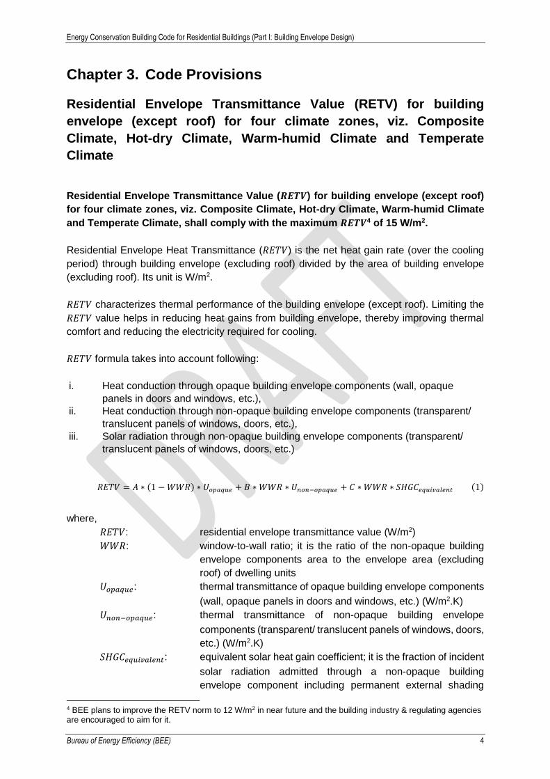
Residential Envelope Transmittance Value (𝑹𝑬𝑻𝑽) for building envelope (except roof)
for four climate zones, viz. Composite Climate, Hot-dry Climate, Warm-humid Climate
and Temperate Climate, shall comply with the maximum 𝑹𝑬𝑻𝑽4 of 15 W/m2.
Residential Envelope Heat Transmittance (𝑅𝐸𝑇𝑉) is the net heat gain rate (over the cooling
period) through building envelope (excluding roof) divided by the area of building envelope
(excluding roof). Its unit is W/m2.
𝑅𝐸𝑇𝑉 characterizes thermal performance of the building envelope (except roof). Limiting the
𝑅𝐸𝑇𝑉 value helps in reducing heat gains from building envelope, thereby improving thermal
comfort and reducing the electricity required for cooling.
𝑅𝐸𝑇𝑉 formula takes into account following:
i. Heat conduction through opaque building envelope components (wall, opaque
panels in doors and windows, etc.),
ii. Heat conduction through non-opaque building envelope components (transparent/
translucent panels of windows, doors, etc.),
iii. Solar radiation through non-opaque building envelope components (transparent/
translucent panels of windows, doors, etc.)
𝑅𝐸𝑇𝑉 = 𝐴 ∗ (1 − 𝑊𝑊𝑅) ∗ 𝑈𝑜𝑝𝑎𝑞𝑢𝑒 + 𝐵 ∗ 𝑊𝑊𝑅 ∗ 𝑈𝑛𝑜𝑛−𝑜𝑝𝑎𝑞𝑢𝑒 + 𝐶 ∗ 𝑊𝑊𝑅 ∗ 𝑆𝐻𝐺𝐶𝑒𝑞𝑢𝑖𝑣𝑎𝑙𝑒𝑛𝑡 (1)
where,
𝑅𝐸𝑇𝑉: residential envelope transmittance value (W/m2)
𝑊𝑊𝑅: window-to-wall ratio; it is the ratio of the non-opaque building
envelope components area to the envelope area (excluding
roof) of dwelling units
𝑈𝑜𝑝𝑎𝑞𝑢𝑒: thermal transmittance of opaque building envelope components
(wall, opaque panels in doors and windows, etc.) (W/m2.K)
𝑈𝑛𝑜𝑛−𝑜𝑝𝑎𝑞𝑢𝑒: thermal transmittance of non-opaque building envelope
components (transparent/ translucent panels of windows, doors,
etc.) (W/m2.K)
𝑆𝐻𝐺𝐶𝑒𝑞𝑢𝑖𝑣𝑎𝑙𝑒𝑛𝑡: equivalent solar heat gain coefficient; it is the fraction of incident
solar radiation admitted through a non-opaque building
envelope component including permanent external shading
4 BEE plans to improve the RETV norm to 12 W/m2 in near future and the building industry & regulating agencies are encouraged to aim for it.
Energy Conservation Building Code for Residential Buildings (Part I: Building Envelope Design)
Bureau of Energy Efficiency (BEE) 5
projection, both directly transmitted, and absorbed and
subsequently released inward through conduction, convection
and radiation (for calculation, refer to Annexure 2)
𝐴, 𝐵 & 𝐶: coefficients (values given in Table 1)
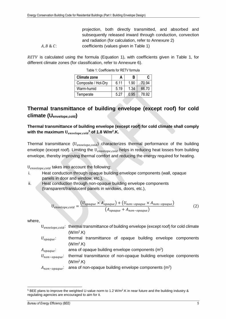
𝑅𝐸𝑇𝑉 is calculated using the formula (Equation 1), with coefficients given in Table 1, for
different climate zones (for classification, refer to Annexure 6).
Table 1: Coefficients for RETV formula
Climate zone A B C
Composite / Hot-Dry 6.11 1.90 70.94
Warm-humid 5.19 1.34 66.70
Temperate 5.27 0.95 78.92
Thermal transmittance of building envelope (except roof) for cold
climate (Uenvelope,cold)
Thermal transmittance of building envelope (except roof) for cold climate shall comply
with the maximum 𝐔𝒆𝒏𝒗𝒆𝒍𝒐𝒑𝒆,𝒄𝒐𝒍𝒅5 of 1.8 W/m2.K.
Thermal transmittance (U𝑒𝑛𝑣𝑒𝑙𝑜𝑝𝑒,𝑐𝑜𝑙𝑑) characterizes thermal performance of the building
envelope (except roof). Limiting the U𝑒𝑛𝑣𝑒𝑙𝑜𝑝𝑒,𝑐𝑜𝑙𝑑 helps in reducing heat losses from building
envelope, thereby improving thermal comfort and reducing the energy required for heating.
U𝑒𝑛𝑣𝑒𝑙𝑜𝑝𝑒,𝑐𝑜𝑙𝑑 takes into account the following:
i. Heat conduction through opaque building envelope components (wall, opaque
panels in door and window, etc.),
ii. Heat conduction through non-opaque building envelope components
(transparent/translucent panels in windows, doors, etc.),
U𝑒𝑛𝑣𝑒𝑙𝑜𝑝𝑒,𝑐𝑜𝑙𝑑 =(𝑈𝑜𝑝𝑎𝑞𝑢𝑒 × 𝐴𝑜𝑝𝑎𝑞𝑢𝑒) + (𝑈𝑛𝑜𝑛−𝑜𝑝𝑎𝑞𝑢𝑒 × 𝐴𝑛𝑜𝑛−𝑜𝑝𝑎𝑞𝑢𝑒)
(𝐴𝑜𝑝𝑎𝑞𝑢𝑒 + 𝐴𝑛𝑜𝑛−𝑜𝑝𝑎𝑞𝑢𝑒)(2)
where,
U𝑒𝑛𝑣𝑒𝑙𝑜𝑝𝑒,𝑐𝑜𝑙𝑑: thermal transmittance of building envelope (except roof) for cold climate
(W/m2.K)
𝑈𝑜𝑝𝑎𝑞𝑢𝑒: thermal transmittance of opaque building envelope components
(W/m2.K)
𝐴𝑜𝑝𝑎𝑞𝑢𝑒: area of opaque building envelope components (m2)
𝑈𝑛𝑜𝑛−𝑜𝑝𝑎𝑞𝑢𝑒: thermal transmittance of non-opaque building envelope components
(W/m2.K)
𝐴𝑛𝑜𝑛−𝑜𝑝𝑎𝑞𝑢𝑒: area of non-opaque building envelope components (m2)
5 BEE plans to improve the weighted U-value norm to 1.2 W/m2.K in near future and the building industry & regulating agencies are encouraged to aim for it.

Energy Conservation Building Code for Residential Buildings (Part I: Building Envelope Design)
Bureau of Energy Efficiency (BEE) 6
Thermal transmittance of roof (Uroof)
Thermal transmittance of roof shall comply with the maximum U𝑟𝑜𝑜𝑓 value of 1.2 W/m2.K.
Thermal transmittance (U𝑟𝑜𝑜𝑓) characterizes thermal performance of the roof of the building.
Limiting the U𝑟𝑜𝑜𝑓 helps in reducing heat gains or losses from the roof, thereby improving
thermal comfort and reducing the energy required for cooling or heating.
Openable window-to-floor area ratio (WFRop)
Openable window-to-floor area ratio shall comply with the minimum 𝑊𝐹𝑅𝑜𝑝 values as
given in Table 2.
Openable window-to-floor area ratio (𝑊𝐹𝑅𝑜𝑝) indicates potential of using external air for
ventilation. Ensuring minimum 𝑊𝐹𝑅𝑜𝑝 helps in ventilation, improvement in thermal comfort
and reduction in cooling energy.
The openable window-to-floor ratio (𝑊𝐹𝑅𝑜𝑝) is the ratio of openable area to the built-up area
of dwelling units.
𝑊𝐹𝑅𝑜𝑝 =𝐴𝑜𝑝𝑒𝑛𝑎𝑏𝑙𝑒
𝐴𝑏𝑢𝑖𝑙𝑡−𝑢𝑝
(3)
where,
𝑊𝐹𝑅𝑜𝑝: openable window-to-floor ratio
𝐴𝑜𝑝𝑒𝑛𝑎𝑏𝑙𝑒: openable area (m2); openable area of all windows and
ventilators area, excluding doors, opening directly to the
external air or into an open balcony or “verandah”
𝐴𝑏𝑢𝑖𝑙𝑡−𝑢𝑝: built-up area of dwelling units (m2); the covered area of all
dwelling units, including the area covered by walls, but
excepting the balcony area
The openable window-to-floor area ratio, (𝑊𝐹𝑅𝑜𝑝), shall not be less than the values given in
Table 2.
Table 2: Minimum requirement of window-to-floor area ratio, WFRop
Climatic Zone Minimum 𝑾𝑭𝑹𝒐𝒑
Composite / Hot and dry 10.00%
Warm and humid 16.66%
Temperate 12.50%
Cold 8.33%
(Source: adapted from model building bye-laws, 2016)
Energy Conservation Building Code for Residential Buildings (Part I: Building Envelope Design)
Bureau of Energy Efficiency (BEE) 7
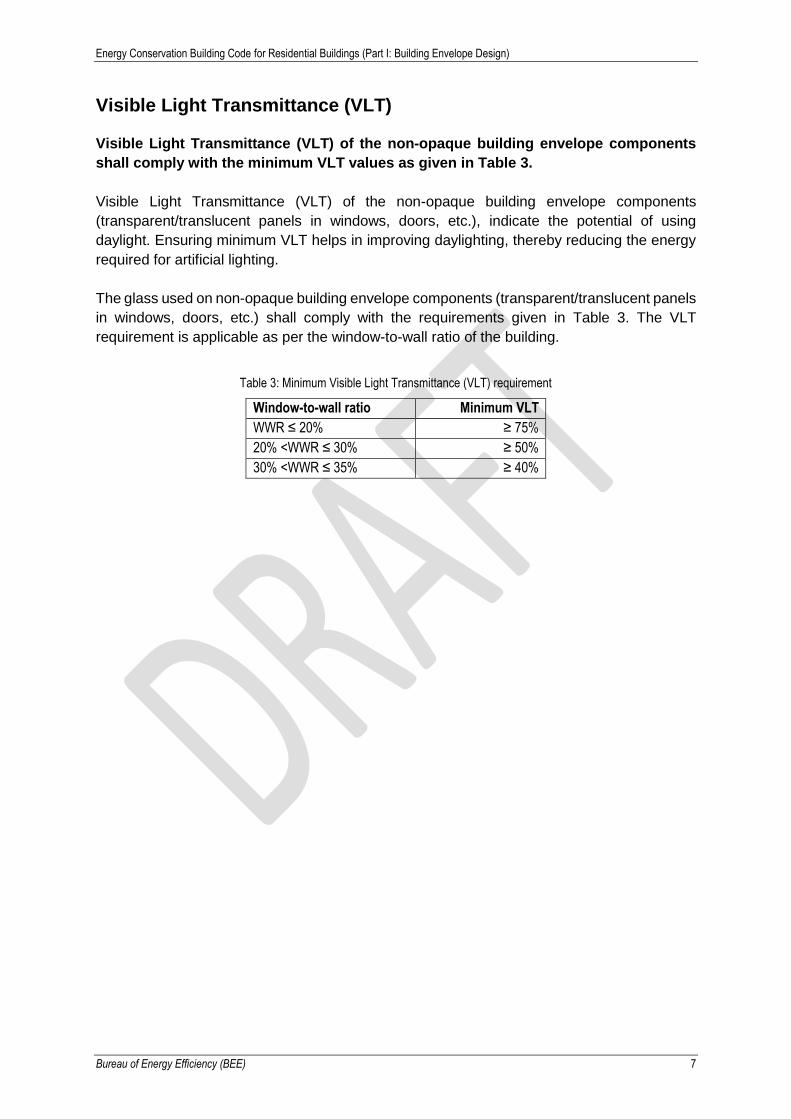
Visible Light Transmittance (VLT)
Visible Light Transmittance (VLT) of the non-opaque building envelope components
shall comply with the minimum VLT values as given in Table 3.
Visible Light Transmittance (VLT) of the non-opaque building envelope components
(transparent/translucent panels in windows, doors, etc.), indicate the potential of using
daylight. Ensuring minimum VLT helps in improving daylighting, thereby reducing the energy
required for artificial lighting.
The glass used on non-opaque building envelope components (transparent/translucent panels
in windows, doors, etc.) shall comply with the requirements given in Table 3. The VLT
requirement is applicable as per the window-to-wall ratio of the building.
Table 3: Minimum Visible Light Transmittance (VLT) requirement
Window-to-wall ratio Minimum VLT
WWR ≤ 20% ≥ 75%
20% <WWR ≤ 30% ≥ 50%
30% <WWR ≤ 35% ≥ 40%

Energy Conservation Building Code for Residential Buildings (Part I: Building Envelope Design)
Bureau of Energy Efficiency (BEE) 8
Chapter 4. Code Compliance
Each building block in a project is required to comply with the code. For compliance following
conditions shall be met.
Composite Climate, Hot-dry Climate, Warm-humid Climate and
Temperate Climate
Step 1: Openable window-to-floor area ratio shall comply with the minimum 𝑊𝐹𝑅𝑜𝑝 values as
given in Table 2 of section 3.4. For calculation of 𝑊𝐹𝑅𝑜𝑝 refer to Annexure 4.
Step 2: Visible Light Transmittance (VLT) of the non-opaque building envelope components
shall comply with the minimum VLT values as given in Table 3 of section 3.5.
a) For calculation of WWR refer to Annexure 3.
b) Refer product specifications to know VLT of the transparent / translucent panels in
windows and doors.
Step 3: Thermal transmittance of roof shall comply with the maximum U𝑟𝑜𝑜𝑓 value of 1.2
W/m2.K (refer section 3.3). For checking the U value of typical roof or to calculate U values of
roof, refer to Annexure 1.
Step 4: Residential Envelope Transmittance Value (RETV) for building envelope (except roof),
shall comply with the maximum RETV of 15 W/m2 (refer section 3.1)
a) Equation 1 is to be used for the calculation of RETV, with coefficients selected from
Table 1 as per the climate zone.
b) For calculation of U values refer to Annexure 1.
c) For calculation of Equivalent SHGC refer to Annexure 2.
d) For calculation of WWR refer to Annexure 3.
An example of code compliance is given to Annexure 5 (Example 1).
Cold Climate
Step 1: Openable window-to-floor area ratio shall comply with the minimum 𝑊𝐹𝑅𝑜𝑝 values as
given in Table 2 of section 3.4. For calculation of 𝑊𝐹𝑅𝑜𝑝 refer to Annexure 4.
Step 2: Visible Light Transmittance (VLT) of the non-opaque building envelope components
shall comply with the minimum VLT values as given in Table 3 of section 3.5.
a) For calculation of WWR refer to Annexure 3.
b) Refer product specifications to know VLT of the transparent / translucent panels in
windows and doors.

Energy Conservation Building Code for Residential Buildings (Part I: Building Envelope Design)
Bureau of Energy Efficiency (BEE) 9
Step 3: Thermal transmittance of roof shall comply with the maximum U𝑟𝑜𝑜𝑓 value of 1.2
W/m2.K (refer section 3.3). For checking the U value of typical roof or to calculate U values of
roof, refer to Annexure 1.
Step 4: Thermal transmittance of building envelope (except roof) for cold climate shall comply
with the maximum U𝑒𝑛𝑣𝑒𝑙𝑜𝑝𝑒,𝑐𝑜𝑙𝑑 of 1.8 W/m2.K (refer section 3.2).
a) Equation 2 is to be used for the calculation of U𝑒𝑛𝑣𝑒𝑙𝑜𝑝𝑒,𝑐𝑜𝑙𝑑.
b) For calculation of U values refer to Annexure 1.
An example of code compliance is given to Annexure 5 (Example 2).
Energy Conservation Building Code for Residential Buildings (Part I: Building Envelope Design)
Bureau of Energy Efficiency (BEE) 10
Annexure 1. Calculation of Thermal Transmittance (U
value) of roof and wall
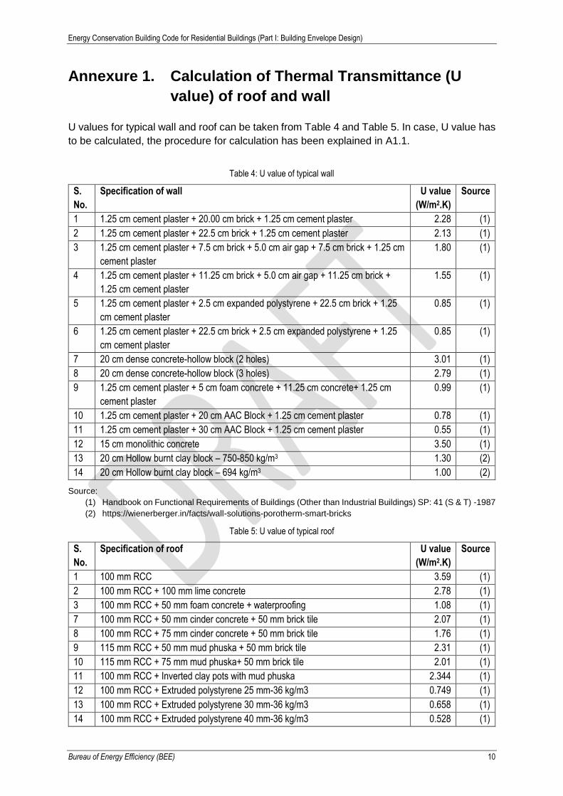
U values for typical wall and roof can be taken from Table 4 and Table 5. In case, U value has
to be calculated, the procedure for calculation has been explained in A1.1.
Table 4: U value of typical wall
S.
No.
Specification of wall U value
(W/m2.K)
Source
1 1.25 cm cement plaster + 20.00 cm brick + 1.25 cm cement plaster 2.28 (1)
2 1.25 cm cement plaster + 22.5 cm brick + 1.25 cm cement plaster 2.13 (1)
3 1.25 cm cement plaster + 7.5 cm brick + 5.0 cm air gap + 7.5 cm brick + 1.25 cm
cement plaster
1.80 (1)
4 1.25 cm cement plaster + 11.25 cm brick + 5.0 cm air gap + 11.25 cm brick +
1.25 cm cement plaster
1.55 (1)
5 1.25 cm cement plaster + 2.5 cm expanded polystyrene + 22.5 cm brick + 1.25
cm cement plaster
0.85 (1)
6 1.25 cm cement plaster + 22.5 cm brick + 2.5 cm expanded polystyrene + 1.25
cm cement plaster
0.85 (1)
7 20 cm dense concrete-hollow block (2 holes) 3.01 (1)
8 20 cm dense concrete-hollow block (3 holes) 2.79 (1)
9 1.25 cm cement plaster + 5 cm foam concrete + 11.25 cm concrete+ 1.25 cm
cement plaster
0.99 (1)
10 1.25 cm cement plaster + 20 cm AAC Block + 1.25 cm cement plaster 0.78 (1)
11 1.25 cm cement plaster + 30 cm AAC Block + 1.25 cm cement plaster 0.55 (1)
12 15 cm monolithic concrete 3.50 (1)
13 20 cm Hollow burnt clay block – 750-850 kg/m3 1.30 (2)
14 20 cm Hollow burnt clay block – 694 kg/m3 1.00 (2)
Source:
(1) Handbook on Functional Requirements of Buildings (Other than Industrial Buildings) SP: 41 (S & T) -1987
(2) https://wienerberger.in/facts/wall-solutions-porotherm-smart-bricks
Table 5: U value of typical roof
S.
No.
Specification of roof U value
(W/m2.K)
Source
1 100 mm RCC 3.59 (1)
2 100 mm RCC + 100 mm lime concrete 2.78 (1)
3 100 mm RCC + 50 mm foam concrete + waterproofing 1.08 (1)
7 100 mm RCC + 50 mm cinder concrete + 50 mm brick tile 2.07 (1)
8 100 mm RCC + 75 mm cinder concrete + 50 mm brick tile 1.76 (1)
9 115 mm RCC + 50 mm mud phuska + 50 mm brick tile 2.31 (1)
10 115 mm RCC + 75 mm mud phuska+ 50 mm brick tile 2.01 (1)
11 100 mm RCC + Inverted clay pots with mud phuska 2.344 (1)
12 100 mm RCC + Extruded polystyrene 25 mm-36 kg/m3 0.749 (1)
13 100 mm RCC + Extruded polystyrene 30 mm-36 kg/m3 0.658 (1)
14 100 mm RCC + Extruded polystyrene 40 mm-36 kg/m3 0.528 (1)

Energy Conservation Building Code for Residential Buildings (Part I: Building Envelope Design)
Bureau of Energy Efficiency (BEE) 11
S.
No.
Specification of roof U value
(W/m2.K)
Source
15 100 mm RCC + Expanded polystyrene 25 mm-24 kg/m3 0.931 (1)
16 100 mm RCC + Expanded polystyrene 30 mm-24 kg/m3 0.823 (1)
17 100 mm RCC + Expanded polystyrene 40 mm-24 kg/m3 0.670 (1)
18 100 mm RCC + Expanded polystyrene 60 mm-24 kg/m3 0.482 (1)
19 100 mm RCC + Phenolic foam 25 mm-32 kg/m3 0.725 (1)
20 100 mm RCC + Phenolic foam 30 mm-32 kg/m3 0.641 (1)
21 100 mm RCC + Phenolic foam 40 mm-32 kg/m3 0.511 (1)
22 100 mm RCC + Polyurethane spray 25 mm-42 ± 2 kg/m3 0.664 (1)
23 100 mm RCC + Polyurethane spray 30 mm-42 ± 2 kg/m3 0.579 (1)
Source:
(1) NBC 2016: Part 11 Approach to Sustainability (Page.27)
A1.1 Calculation procedure for U value of wall and roof a) Calculate thermal resistance 𝑅 of each uniform material layer which constitutes the
building component, as follows:
𝑅𝑖 = 𝑡𝑖
𝑘𝑖
(4)
where, 𝑅𝑖 is the thermal resistance of material 𝑖, m2.K/W
𝑡𝑖 is the thickness of material 𝑖, m
𝑘𝑖 is the thermal conductivity of material 𝑖, W/(m.K)
b) Find the total thermal resistance, 𝑅𝑇, as follows:
𝑅𝑇 =1
ℎ𝑖+
1
ℎ𝑜+ 𝑅1 + 𝑅2 + 𝑅3 + ⋯ (5)
where, 𝑅𝑇 is the total thermal resistance, m2.K/W
ℎ𝑖 is the inside air heat transfer coefficient, W/(m2.K)
ℎ𝑜 is the outside air heat transfer coefficient, W/(m2.K)
𝑅1 is the thermal resistance of material 1, m2.K/W
𝑅2 is the thermal resistance of material 2, m2.K/W
𝑅3 is the thermal resistance of material 3, m2.K/W
Use these default values6 for calculation,
ℎ𝑖 = 9.36 𝑊 (𝑚2. 𝐾)⁄
ℎ𝑜 = 19.86 𝑊 (𝑚2. 𝐾)⁄
Thermal conductivity of commonly used building material7 is given in Table 6, which can be
used to calculate thermal resistance (R value).
6 Source: Handbook on Functional Requirements of Buildings (Other than Industrial Buildings) SP: 41 (S & T) -1987 7 ibid
Energy Conservation Building Code for Residential Buildings (Part I: Building Envelope Design)
Bureau of Energy Efficiency (BEE) 12
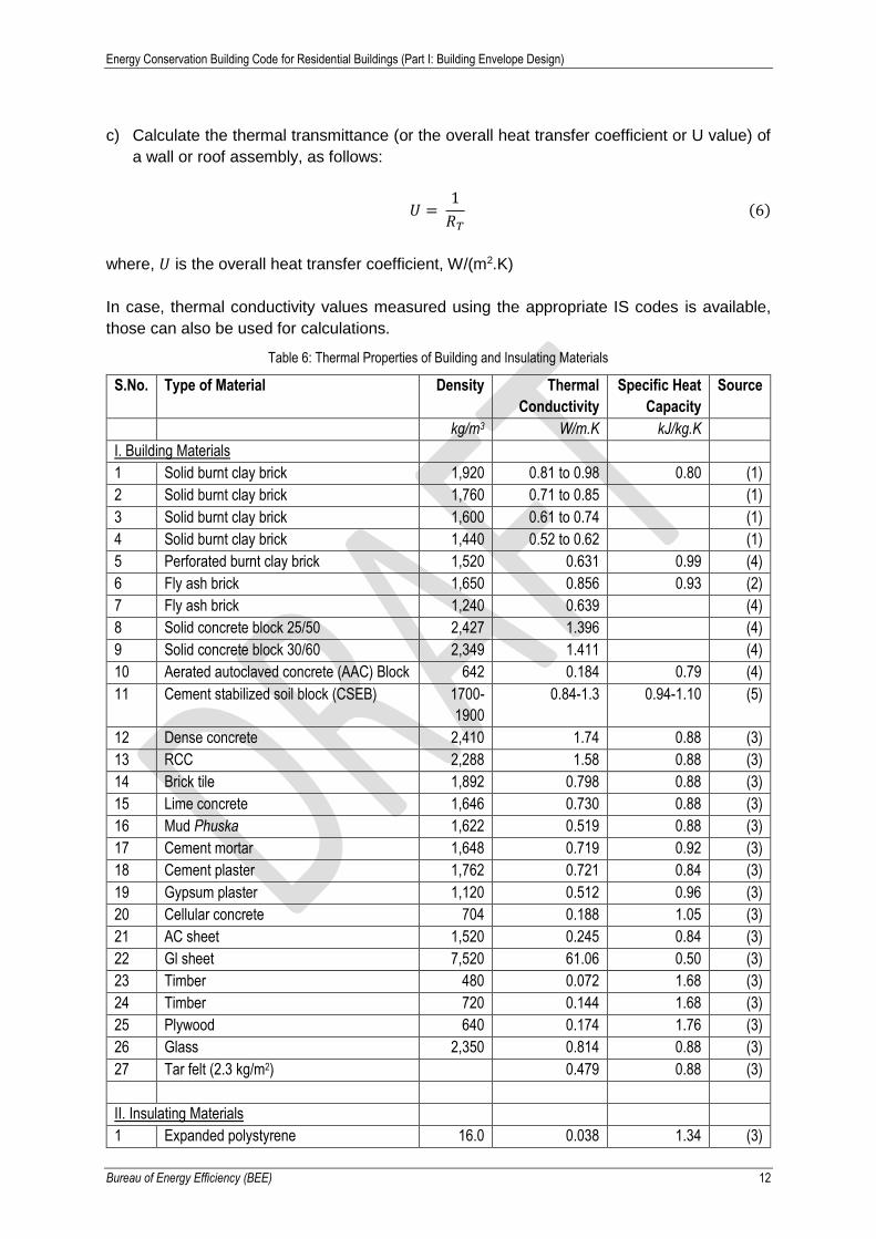
c) Calculate the thermal transmittance (or the overall heat transfer coefficient or U value) of
a wall or roof assembly, as follows:
𝑈 = 1
𝑅𝑇
(6)
where, 𝑈 is the overall heat transfer coefficient, W/(m2.K)
In case, thermal conductivity values measured using the appropriate IS codes is available,
those can also be used for calculations.
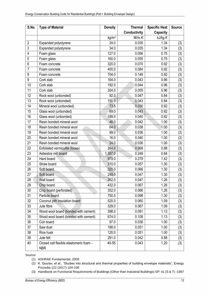
Table 6: Thermal Properties of Building and Insulating Materials
S.No. Type of Material Density Thermal
Conductivity
Specific Heat
Capacity
Source
kg/m3 W/m.K kJ/kg.K
I. Building Materials
1 Solid burnt clay brick 1,920 0.81 to 0.98 0.80 (1)
2 Solid burnt clay brick 1,760 0.71 to 0.85 (1)
3 Solid burnt clay brick 1,600 0.61 to 0.74 (1)
4 Solid burnt clay brick 1,440 0.52 to 0.62 (1)
5 Perforated burnt clay brick 1,520 0.631 0.99 (4)
6 Fly ash brick 1,650 0.856 0.93 (2)
7 Fly ash brick 1,240 0.639 (4)
8 Solid concrete block 25/50 2,427 1.396 (4)
9 Solid concrete block 30/60 2,349 1.411 (4)
10 Aerated autoclaved concrete (AAC) Block 642 0.184 0.79 (4)
11 Cement stabilized soil block (CSEB) 1700-
1900
0.84-1.3 0.94-1.10 (5)
12 Dense concrete 2,410 1.74 0.88 (3)
13 RCC 2,288 1.58 0.88 (3)
14 Brick tile 1,892 0.798 0.88 (3)
15 Lime concrete 1,646 0.730 0.88 (3)
16 Mud Phuska 1,622 0.519 0.88 (3)
17 Cement mortar 1,648 0.719 0.92 (3)
18 Cement plaster 1,762 0.721 0.84 (3)
19 Gypsum plaster 1,120 0.512 0.96 (3)
20 Cellular concrete 704 0.188 1.05 (3)
21 AC sheet 1,520 0.245 0.84 (3)
22 Gl sheet 7,520 61.06 0.50 (3)
23 Timber 480 0.072 1.68 (3)
24 Timber 720 0.144 1.68 (3)
25 Plywood 640 0.174 1.76 (3)
26 Glass 2,350 0.814 0.88 (3)
27 Tar felt (2.3 kg/m2) 0.479 0.88 (3)
II. Insulating Materials
1 Expanded polystyrene 16.0 0.038 1.34 (3)
Energy Conservation Building Code for Residential Buildings (Part I: Building Envelope Design)
Bureau of Energy Efficiency (BEE) 13
S.No. Type of Material Density Thermal
Conductivity
Specific Heat
Capacity
Source
kg/m3 W/m.K kJ/kg.K
2 Expanded polystyrene 24.0 0.035 1.34 (3)
3 Expanded polystyrene 34.0 0.035 1.34 (3)
4 Foam glass 127.0 0.056 0.75 (3)
5 Foam glass 160.0 0.055 0.75 (3)
6 Foam concrete 320.0 0.070 0.92 (3)
7 Foam concrete 400.0 0.084 0.92 (3)
8 Foam concrete 704.0 0.149 0.92 (3)
9 Cork slab 164.0 0.043 0.96 (3)
10 Cork slab 192.0 0.044 0.96 (3)
11 Cork slab 304.0 0.055 0.96 (3)
12 Rock wool (unbonded) 92.0 0.047 0.84 (3)
13 Rock wool (unbonded) 150.0 0.043 0.84 (3)
14 Mineral wool (unbonded) 73.5 0.030 0.92 (3)
15 Glass wool (unbonded) 69.0 0.043 0.92 (3)
16 Glass wool (unbonded) 189.0 0.040 0.92 (3)
17 Resin bonded mineral wool 48.0 0.042 1.00 (3)
18 Resin bonded mineral wool 64.0 0.038 1.00 (3)
19 Resin bonded mineral wool 99.0 0.036 1.00 (3)
20 Resin bonded mineral wool 16.0 0.040 1.00 (3)
21 Resin bonded mineral wool 24.0 0.036 1.00 (3)
22 Exfoliated vermiculite (loose) 264.0 0.069 0.88 (3)
23 Asbestos mill board 1,397.0 0.249 0.84 (3)
24 Hard board 979.0 0.279 1.42 (3)
25 Straw board 310.0 0.057 1.30 (3)
26 Soft board 320.0 0.066 1.30 (3)
27 Soft board 249.0 0.047 1.30 (3)
28 Wall board 262.0 0.047 1.26 (3)
29 Chip board 432.0 0.067 1.26 (3)
30 Chip board (perforated) 352.0 0.066 1.26 (3)
31 Particle board 750.0 0.098 1.30 (3)
32 Coconut pith insulation board 520.0 0.060 1.09 (3)
33 Jute fibre 329.0 0.067 1.09 (3)
34 Wood wool board (bonded with cement) 398.0 0.081 1.13 (3)
35 Wood wool board (bonded with cement) 674.0 0.108 1.13 (3)
36 Coir board 97.0 0.038 1.00 (3)
37 Saw dust 188.0 0.051 1.00 (3)
38 Rice husk 120.0 0.051 1.00 (3)
39 Jute felt 291.0 0.042 0.88 (3)
40 Closed cell flexible elastomeric foam -
NBR
40-55 0.043 1.20 (3)
Source:
(1) ASHRAE Fundamental, 2009
(2) K. Gourav, et al., “Studies into structural and thermal properties of building envelope materials”, Energy
Procedia 122 (2017) 104-108
(3) Handbook on Functional Requirements of Buildings (Other than Industrial Buildings) SP: 41 (S & T) -1987
Energy Conservation Building Code for Residential Buildings (Part I: Building Envelope Design)
Bureau of Energy Efficiency (BEE) 14
(4) ECBC 2017
(5) Balaji N.C, et al., “Influence of varying mix proportions on thermal performance of soil-cement blocks”,
Building Simulation Applications BSA 2015
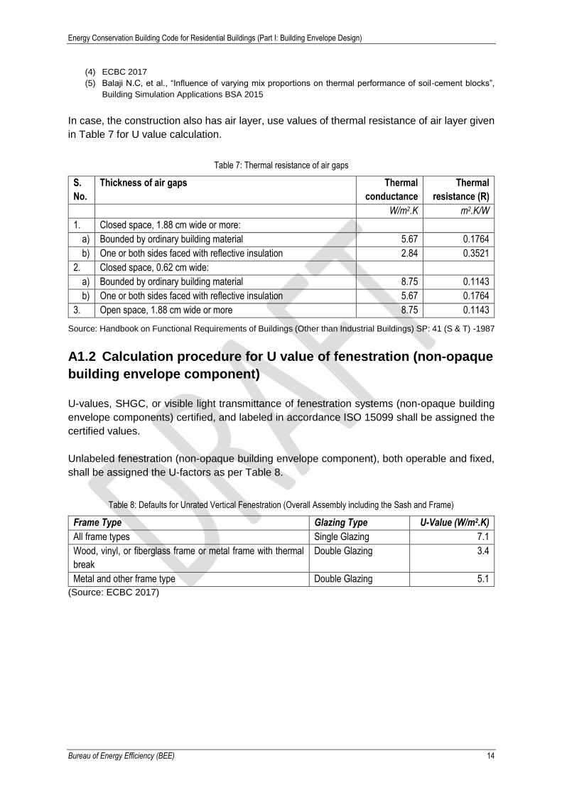
In case, the construction also has air layer, use values of thermal resistance of air layer given
in Table 7 for U value calculation.
Table 7: Thermal resistance of air gaps
S.
No.
Thickness of air gaps Thermal
conductance
Thermal
resistance (R)
W/m2.K m2.K/W
1. Closed space, 1.88 cm wide or more:
a) Bounded by ordinary building material 5.67 0.1764
b) One or both sides faced with reflective insulation 2.84 0.3521
2. Closed space, 0.62 cm wide:
a) Bounded by ordinary building material 8.75 0.1143
b) One or both sides faced with reflective insulation 5.67 0.1764
3. Open space, 1.88 cm wide or more 8.75 0.1143
Source: Handbook on Functional Requirements of Buildings (Other than Industrial Buildings) SP: 41 (S & T) -1987
A1.2 Calculation procedure for U value of fenestration (non-opaque
building envelope component)
U-values, SHGC, or visible light transmittance of fenestration systems (non-opaque building
envelope components) certified, and labeled in accordance ISO 15099 shall be assigned the
certified values.
Unlabeled fenestration (non-opaque building envelope component), both operable and fixed,
shall be assigned the U-factors as per Table 8.
Table 8: Defaults for Unrated Vertical Fenestration (Overall Assembly including the Sash and Frame)
Frame Type Glazing Type U-Value (W/m2.K)
All frame types Single Glazing 7.1
Wood, vinyl, or fiberglass frame or metal frame with thermal
break
Double Glazing 3.4
Metal and other frame type Double Glazing 5.1
(Source: ECBC 2017)

Energy Conservation Building Code for Residential Buildings (Part I: Building Envelope Design)
Bureau of Energy Efficiency (BEE) 15
Annexure 2. Calculation of Equivalent SHGC (As per ECBC 2017)
The calculation needs to be done for fenestration located in 8 cardinal directions i.e. North,
East, South, West, North-east, South-east, South-west & North-west. Vertical fenestration on
non-cardinal direction, shall be categorized under a particular cardinal direction if its
orientation is within ± 22.5° of that cardinal direction.
a) Calculate the projection factor (PF) for permanent external projection, including but not
limited to overhangs, side fins, box frame, verandah, balcony, and fixed canopies, using
the formula:
i. Projection factor, overhang: the ratio of the horizontal depth of the external
shading projection (𝐻) to the sum of the height of the fenestration and the distance
from the top of the fenestration to the bottom of the farthest point of the external
shading projection (𝑉), in consistent units.
𝑃𝐹 =𝐻
𝑉(7)
Figure 1: Projection factor
ii. Projection factor, side/vertical fin: the ratio of the horizontal depth of the external
shading projection to the distance from the window jamb to the farthest point of the
external shading projection, in consistent units.
iii. Projection Factor, overhang and side/vertical fin: average of ratio projection factor
for overhang only and projection factor of side fin only.
b) Calculate the Shading Equivalent Factors (SEF), using the formula:
𝑆𝐸𝐹 = 𝐶3 × 𝑃𝐹3 + 𝐶2 × 𝑃𝐹2 + 𝐶1 × 𝑃𝐹 + 𝐶0 (8)
This formula is developed for 𝑃𝐹 ranging from 0.25 to 1.0. If the 𝑃𝐹 calculated for the shading
is below 0.25, then a value of 0.25 shall be used. Similarly, If the 𝑃𝐹 calculated for the shading
is above 1.0, then a value of 1.0 shall be used.
Energy Conservation Building Code for Residential Buildings (Part I: Building Envelope Design)
Bureau of Energy Efficiency (BEE) 16
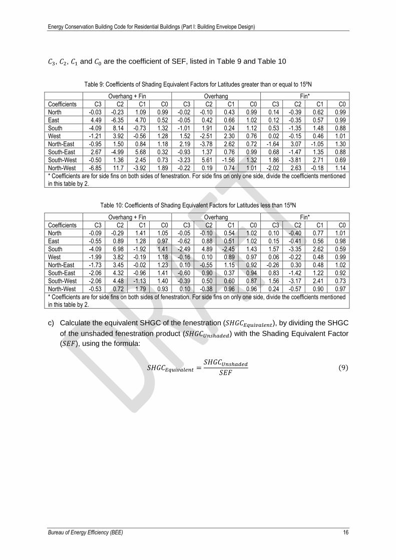
𝐶3, 𝐶2, 𝐶1 and 𝐶0 are the coefficient of SEF, listed in Table 9 and Table 10
Table 9: Coefficients of Shading Equivalent Factors for Latitudes greater than or equal to 15ºN
Overhang + Fin Overhang Fin*
Coefficients C3 C2 C1 C0 C3 C2 C1 C0 C3 C2 C1 C0
North -0.03 -0.23 1.09 0.99 -0.02 -0.10 0.43 0.99 0.14 -0.39 0.62 0.99
East 4.49 -6.35 4.70 0.52 -0.05 0.42 0.66 1.02 0.12 -0.35 0.57 0.99
South -4.09 8.14 -0.73 1.32 -1.01 1.91 0.24 1.12 0.53 -1.35 1.48 0.88
West -1.21 3.92 -0.56 1.28 1.52 -2.51 2.30 0.76 0.02 -0.15 0.46 1.01
North-East -0.95 1.50 0.84 1.18 2.19 -3.78 2.62 0.72 -1.64 3.07 -1.05 1.30
South-East 2.67 -4.99 5.68 0.32 -0.93 1.37 0.76 0.99 0.68 -1.47 1.35 0.88
South-West -0.50 1.36 2.45 0.73 -3.23 5.61 -1.56 1.32 1.86 -3.81 2.71 0.69
North-West -6.85 11.7 -3.92 1.89 -0.22 0.19 0.74 1.01 -2.02 2.63 -0.18 1.14
* Coefficients are for side fins on both sides of fenestration. For side fins on only one side, divide the coefficients mentioned in this table by 2.
Table 10: Coefficients of Shading Equivalent Factors for Latitudes less than 15ºN
Overhang + Fin Overhang Fin*
Coefficients C3 C2 C1 C0 C3 C2 C1 C0 C3 C2 C1 C0
North -0.09 -0.29 1.41 1.05 -0.05 -0.10 0.54 1.02 0.10 -0.40 0.77 1.01
East -0.55 0.89 1.28 0.97 -0.62 0.88 0.51 1.02 0.15 -0.41 0.56 0.98
South -4.09 6.98 -1.92 1.41 -2.49 4.89 -2.45 1.43 1.57 -3.35 2.62 0.59
West -1.99 3.82 -0.19 1.18 -0.16 0.10 0.89 0.97 0.06 -0.22 0.48 0.99
North-East -1.73 3.45 -0.02 1.23 0.10 -0.55 1.15 0.92 -0.26 0.30 0.48 1.02
South-East -2.06 4.32 -0.96 1.41 -0.60 0.90 0.37 0.94 0.83 -1.42 1.22 0.92
South-West -2.06 4.48 -1.13 1.40 -0.39 0.50 0.60 0.87 1.56 -3.17 2.41 0.73
North-West -0.53 0.72 1.79 0.93 0.10 -0.38 0.96 0.96 0.24 -0.57 0.90 0.97
* Coefficients are for side fins on both sides of fenestration. For side fins on only one side, divide the coefficients mentioned in this table by 2.
c) Calculate the equivalent SHGC of the fenestration (𝑆𝐻𝐺𝐶𝐸𝑞𝑢𝑖𝑣𝑎𝑙𝑒𝑛𝑡), by dividing the SHGC
of the unshaded fenestration product (𝑆𝐻𝐺𝐶𝑈𝑛𝑠ℎ𝑎𝑑𝑒𝑑) with the Shading Equivalent Factor
(𝑆𝐸𝐹), using the formula:
𝑆𝐻𝐺𝐶𝐸𝑞𝑢𝑖𝑣𝑎𝑙𝑒𝑛𝑡 =𝑆𝐻𝐺𝐶𝑈𝑛𝑠ℎ𝑎𝑑𝑒𝑑
𝑆𝐸𝐹(9)
Energy Conservation Building Code for Residential Buildings (Part I: Building Envelope Design)
Bureau of Energy Efficiency (BEE) 17
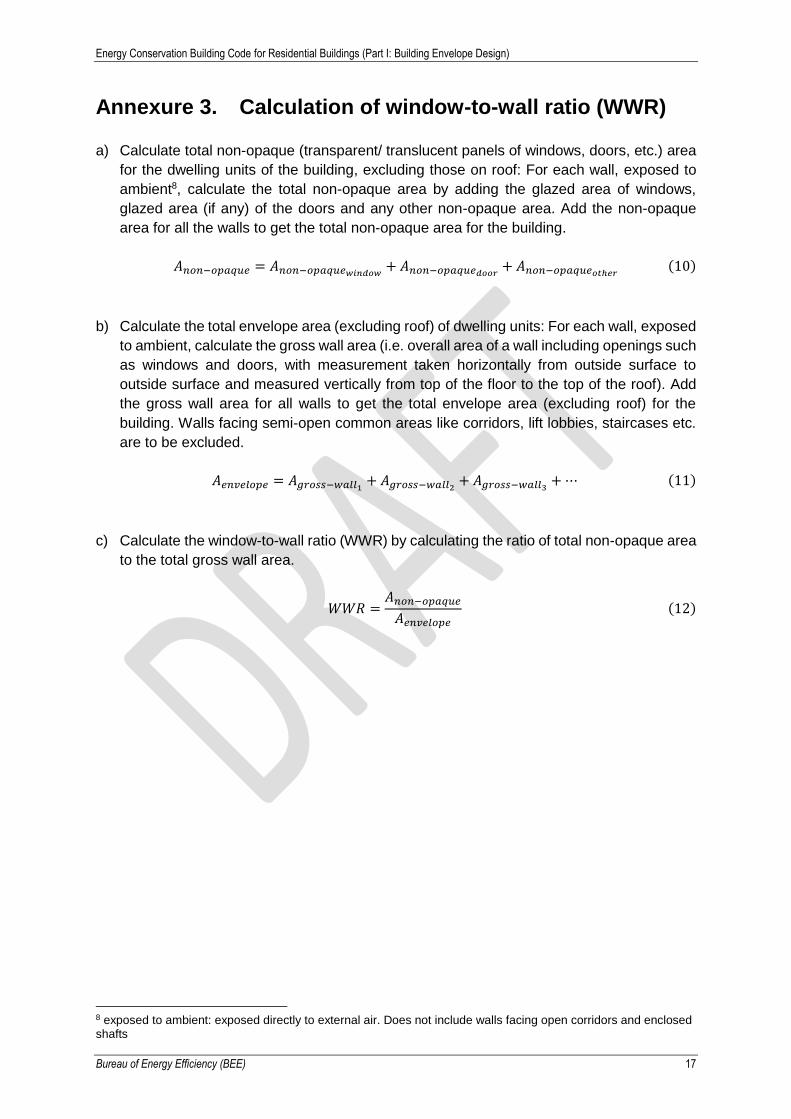
Annexure 3. Calculation of window-to-wall ratio (WWR)
a) Calculate total non-opaque (transparent/ translucent panels of windows, doors, etc.) area
for the dwelling units of the building, excluding those on roof: For each wall, exposed to
ambient8, calculate the total non-opaque area by adding the glazed area of windows,
glazed area (if any) of the doors and any other non-opaque area. Add the non-opaque
area for all the walls to get the total non-opaque area for the building.
𝐴𝑛𝑜𝑛−𝑜𝑝𝑎𝑞𝑢𝑒 = 𝐴𝑛𝑜𝑛−𝑜𝑝𝑎𝑞𝑢𝑒𝑤𝑖𝑛𝑑𝑜𝑤+ 𝐴𝑛𝑜𝑛−𝑜𝑝𝑎𝑞𝑢𝑒𝑑𝑜𝑜𝑟
+ 𝐴𝑛𝑜𝑛−𝑜𝑝𝑎𝑞𝑢𝑒𝑜𝑡ℎ𝑒𝑟(10)
b) Calculate the total envelope area (excluding roof) of dwelling units: For each wall, exposed
to ambient, calculate the gross wall area (i.e. overall area of a wall including openings such
as windows and doors, with measurement taken horizontally from outside surface to
outside surface and measured vertically from top of the floor to the top of the roof). Add
the gross wall area for all walls to get the total envelope area (excluding roof) for the
building. Walls facing semi-open common areas like corridors, lift lobbies, staircases etc.
are to be excluded.
𝐴𝑒𝑛𝑣𝑒𝑙𝑜𝑝𝑒 = 𝐴𝑔𝑟𝑜𝑠𝑠−𝑤𝑎𝑙𝑙1+ 𝐴𝑔𝑟𝑜𝑠𝑠−𝑤𝑎𝑙𝑙2
+ 𝐴𝑔𝑟𝑜𝑠𝑠−𝑤𝑎𝑙𝑙3+ ⋯ (11)
c) Calculate the window-to-wall ratio (WWR) by calculating the ratio of total non-opaque area
to the total gross wall area.
𝑊𝑊𝑅 =𝐴𝑛𝑜𝑛−𝑜𝑝𝑎𝑞𝑢𝑒
𝐴𝑒𝑛𝑣𝑒𝑙𝑜𝑝𝑒
(12)
8 exposed to ambient: exposed directly to external air. Does not include walls facing open corridors and enclosed shafts

Energy Conservation Building Code for Residential Buildings (Part I: Building Envelope Design)
Bureau of Energy Efficiency (BEE) 18
Annexure 4. Calculation of window operable area to floor
area ratio (WFRop)
a) Calculate the openable area by adding the openable area of windows and ventilators
(excluding doors) of all the dwelling units, which opens directly to the external air,
ventilation shaft or into an open balcony or “verandah”.
𝐴𝑜𝑝𝑒𝑛𝑎𝑏𝑙𝑒 = 𝐴𝑜𝑝𝑒𝑛𝑎𝑏𝑙𝑒𝑤𝑖𝑛𝑑𝑜𝑤+ 𝐴𝑜𝑝𝑒𝑛𝑎𝑏𝑙𝑒𝑣𝑒𝑛𝑡𝑖𝑙𝑎𝑡𝑜𝑟
(13)
If case exact openable area is not known, following default values can be used:
Table 11: Default openable area to opening area ratio
Type of window Openable area / opening area
Casement window 0.9
Sliding window (2 panes) 0.5
Sliding window (3 panes) 0.67
b) Calculate the built-up area by adding the built-up area of all the dwelling units (DU). This
includes area covered by the walls but excludes the balcony area.
𝐴𝑏𝑢𝑖𝑙𝑡−𝑢𝑝 𝑎𝑟𝑒𝑎 = 𝐴𝑏𝑢𝑖𝑙𝑡−𝑢𝑝 𝑎𝑟𝑒𝑎𝐷𝑈1+ 𝐴𝑏𝑢𝑖𝑙𝑡−𝑢𝑝 𝑎𝑟𝑒𝑎𝐷𝑈2
+ 𝐴𝑏𝑢𝑖𝑙𝑡−𝑢𝑝 𝑎𝑟𝑒𝑎𝐷𝑈3+ ⋯ (14)
c) Calculate the window operable area to floor area ratio (WFRop) by calculating the ratio of
openable area to the built-up area.
𝑊𝐹𝑅𝑜𝑝 =𝐴𝑜𝑝𝑒𝑛𝑎𝑏𝑙𝑒
𝐴𝑏𝑢𝑖𝑙𝑡−𝑢𝑝 𝑎𝑟𝑒𝑎
(15)

Energy Conservation Building Code for Residential Buildings (Part I: Building Envelope Design)
Bureau of Energy Efficiency (BEE) 19
Annexure 5. Examples of Code Compliance Example 1: A 7-storey housing project in Rajkot is trying to comply with the residential code.
There are 11 residential towers in this project. The built-up area of each dwelling unit (DU) is
32.65 m2.
There are 3 windows (W, W1, W2) and 1 door (D2) in each DU exposed to ambient. The
windows are either fully glazed or partially glazed (glass and PVC panels) and are casement
windows. The door is opaque with PVC panel. Each DU has 2 ventilators (V) in the bath and
toilet, which face a ventilation shaft. The details of the exposed door, windows, and ventilators
are given below.
Table 12: Details of exposed door, windows and ventilators
Opening
(Window/Door/
ventilator)
Name
Opening
Width
(m)
Opening
Height
(m)
Opening
Area (m2)
Width of
Glass in
Opening (m)
Height of
Glass in
Opening (m)
Glass Area
in opening
(m2)
Opaque
area (m2)
W 1.20 1.60 1.92 1.2 0.53 0.64 1.28
W1 0.80 1.30 1.04 0.8 0.43 0.35 0.69
W2 0.80 1.60 1.28 0.80 1.60 1.28 0.00
D2 0.75 2.50 1.88 0 0 0.00 1.87
V (2 nos.) 0.65 0.40 0.26 0.65 0.40 0.26 0.00
Material details are as follows:
Table 13: Details of construction material
Wall 200mm AAC blocks with plaster on both sides
Roof 150mm RCC with 40mm polyurethane foam (PUF) insulation
Glass in windows Single clear glass with SHGC 0.8, VLT 85% and U-value 5.8 W/(m2.K)
PVC panel 4mm thick PVC panel used in doors and windows
Does this project comply with the code?
Figure 2: Layout plan of the project
Figure 3: Plan of a typical DU
Energy Conservation Building Code for Residential Buildings (Part I: Building Envelope Design)
Bureau of Energy Efficiency (BEE) 20
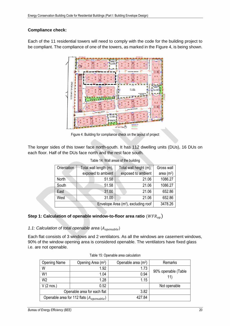
Compliance check:
Each of the 11 residential towers will need to comply with the code for the building project to
be compliant. The compliance of one of the towers, as marked in the Figure 4, is being shown.
Figure 4: Building for compliance check on the layout of project
The longer sides of this tower face north-south. It has 112 dwelling units (DUs), 16 DUs on
each floor. Half of the DUs face north and the rest face south.
Table 14: Wall areas of the building
Orientation Total wall length (m),
exposed to ambient
Total wall height (m),
exposed to ambient
Gross wall
area (m2)
North 51.58 21.06 1086.27
South 51.58 21.06 1086.27
East 31.00 21.06 652.86
West 31.00 21.06 652.86
Envelope Area (m2), excluding roof 3478.26
Step 1: Calculation of openable window-to-floor area ratio (𝑊𝐹𝑅𝑜𝑝)
1.1: Calculation of total openable area (𝐴𝑜𝑝𝑒𝑛𝑎𝑏𝑙𝑒)
Each flat consists of 3 windows and 2 ventilators. As all the windows are casement windows,
90% of the window opening area is considered openable. The ventilators have fixed glass
i.e. are not openable.
Table 15: Openable area calculation
Opening Name Opening Area (m2) Openable area (m2) Remarks
W 1.92 1.73 90% openable (Table
11) W1 1.04 0.94
W2 1.28 1.15
V (2 nos.) 0.52 Not openable
Openable area for each flat 3.82
Openable area for 112 flats (𝐴𝑜𝑝𝑒𝑛𝑎𝑏𝑙𝑒) 427.84

Energy Conservation Building Code for Residential Buildings (Part I: Building Envelope Design)
Bureau of Energy Efficiency (BEE) 21
1.2: Calculation of total built-up area (𝐴𝑏𝑢𝑖𝑙𝑡−𝑢𝑝 𝑎𝑟𝑒𝑎)
𝐴𝑏𝑢𝑖𝑙𝑡−𝑢𝑝 𝑎𝑟𝑒𝑎 = 𝑛𝑜. 𝑜𝑓 𝐷𝑈𝑠 × 𝑏𝑢𝑖𝑙𝑡 − 𝑢𝑝 𝑎𝑟𝑒𝑎 𝑜𝑓 1 𝐷𝑈
= 112 × 32.65 = 3656.80 𝑚2
1.3: Calculate the window operable area to floor area ratio (𝑊𝐹𝑅𝑜𝑝)
𝑊𝐹𝑅𝑜𝑝 =𝐴𝑜𝑝𝑒𝑛𝑎𝑏𝑙𝑒
𝐴𝑏𝑢𝑖𝑙𝑡−𝑢𝑝 𝑎𝑟𝑒𝑎=
427.84
3656.80= 11.7%
Rajkot is in the composite climate. As per Table 2, the minimum 𝑊𝐹𝑅𝑜𝑝 for this climate is
10%. Thus, this project complies with this requirement.
Step 2: Calculation of visible Light Transmittance (VLT)
2.1: Calculation of window-to-wall ratio (𝑊𝑊𝑅)
There are 3 windows and 1 door in each DU exposed to ambient. The windows are either fully
glazed or partially glazed (glass and PVC panels). The door is opaque with PVC panel.
Table 16: Calculation of window-to-wall ratio
Orientation Opening
Name
Opening
Area (m2)
Non-opaque Area
in opening (m2)
No. of
openings
Total Opening
area (m2)
Total Non-Opaque
Area (m2)
North W 1.92 0.64 56 107.52 35.84
North W1 1.04 0.35 56 58.24 19.41
North W2 1.28 1.28 56 71.68 71.68
North D2 1.88 0.00 56 105.00 0.00
South W 1.92 0.64 56 107.52 35.84
South W1 1.04 0.35 56 58.24 19.41
South W2 1.28 1.28 56 71.68 71.68
South D2 1.88 0.00 56 105.00 0.00
Total 684.88 253.86
𝑊𝑊𝑅 =𝐴𝑛𝑜𝑛−𝑜𝑝𝑎𝑞𝑢𝑒
𝐴𝑒𝑛𝑣𝑒𝑙𝑜𝑝𝑒=
253.86
3478.26= 0.073
As per Table 3, the minimum VLT for WWR ≤ 20% is 75%. The glass used in this project has
a VLT of 85% (as per certified specification for the product). Thus, this project complies with
this requirement.
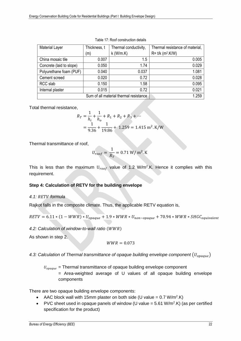
Step 3: Thermal transmittance of roof (𝑼𝒓𝒐𝒐𝒇)
3.1: Calculation of Thermal transmittance of roof (𝑈𝑟𝑜𝑜𝑓)
The roof of this building comprises of the following material layers
Energy Conservation Building Code for Residential Buildings (Part I: Building Envelope Design)
Bureau of Energy Efficiency (BEE) 22
Table 17: Roof construction details
Material Layer Thickness, t
(m)
Thermal conductivity,
k (W/m.K)
Thermal resistance of material,
R= t/k (m2.K/W)
China mosaic tile 0.007 1.5 0.005
Concrete (laid to slope) 0.050 1.74 0.029
Polyurethane foam (PUF) 0.040 0.037 1.081
Cement screed 0.020 0.72 0.028
RCC slab 0.150 1.58 0.095
Internal plaster 0.015 0.72 0.021
Sum of all material thermal resistance 1.259
Total thermal resistance,
𝑅𝑇 =1
ℎ𝑖+
1
ℎ𝑜+ 𝑅1 + 𝑅2 + 𝑅3 + ⋯
=1
9.36+
1
19.86+ 1.259 = 1.415 m2. K/W
Thermal transmittance of roof,
𝑈𝑟𝑜𝑜𝑓 = 1
𝑅𝑇= 0.71 W/ m2. K
This is less than the maximum U𝑟𝑜𝑜𝑓 value of 1.2 W/m2.K. Hence it complies with this
requirement.
Step 4: Calculation of RETV for the building envelope
4.1: 𝑅𝐸𝑇𝑉 formula
Rajkot falls in the composite climate. Thus, the applicable RETV equation is,
𝑅𝐸𝑇𝑉 = 6.11 ∗ (1 − 𝑊𝑊𝑅) ∗ 𝑈𝑜𝑝𝑎𝑞𝑢𝑒 + 1.9 ∗ 𝑊𝑊𝑅 ∗ 𝑈𝑛𝑜𝑛−𝑜𝑝𝑎𝑞𝑢𝑒 + 70.94 ∗ 𝑊𝑊𝑅 ∗ 𝑆𝐻𝐺𝐶𝑒𝑞𝑢𝑖𝑣𝑎𝑙𝑒𝑛𝑡
4.2: Calculation of window-to-wall ratio (𝑊𝑊𝑅)
As shown in step 2.
𝑊𝑊𝑅 = 0.073
4.3: Calculation of Thermal transmittance of opaque building envelope component (𝑈𝑜𝑝𝑎𝑞𝑢𝑒)
𝑈𝑜𝑝𝑎𝑞𝑢𝑒 = Thermal transmittance of opaque building envelope component
= Area-weighted average of U values of all opaque building envelope
components
There are two opaque building envelope components:
• AAC block wall with 15mm plaster on both side (U value = 0.7 W/m2.K)
• PVC sheet used in opaque panels of window (U value = 5.61 W/m2.K) (as per certified
specification for the product)

Energy Conservation Building Code for Residential Buildings (Part I: Building Envelope Design)
Bureau of Energy Efficiency (BEE) 23
[U value of AAC block and PVC sheet is calculated the same way as that shown for the roof.
Thermal conductivity of AAC block is 0.162 W/m.K and that of PVC is 0.19 W/m.K.]
𝑈𝑜𝑝𝑎𝑞𝑢𝑒 =(𝐴𝐴𝐶 𝑏𝑙𝑜𝑐𝑘 𝑤𝑎𝑙𝑙 𝑎𝑟𝑒𝑎 ∗ 𝑈 𝑣𝑎𝑙𝑢𝑒 𝑜𝑓 𝐴𝐴𝐶 𝑤𝑎𝑙𝑙) + (𝑂𝑝𝑎𝑞𝑢𝑒 𝑤𝑖𝑛𝑑𝑜𝑤 𝑎𝑟𝑒𝑎 ∗ 𝑈 𝑣𝑎𝑙𝑢𝑒 𝑜𝑓 𝑃𝑉𝐶)
𝐴𝐴𝐶 𝑏𝑙𝑜𝑐𝑘 𝑤𝑎𝑙𝑙 𝑎𝑟𝑒𝑎 + 𝑂𝑝𝑎𝑞𝑢𝑒 𝑤𝑖𝑛𝑑𝑜𝑤 𝑎𝑟𝑒𝑎
=(2793.38 ∗ 0.7) + (431.02 ∗ 5.61)
2793.38 + 431.02= 1.356 𝑊 𝑚2⁄ . 𝐾
Note:
• AAC block area = Envelope area - Total opening area
• Opaque window area = Total opening area - Total non-opaque area
4.4: Calculation of thermal transmittance of non-opaque building envelope component
(𝑈𝑛𝑜𝑛−𝑜𝑝𝑎𝑞𝑢𝑒)
𝑈𝑛𝑜𝑛−𝑜𝑝𝑎𝑞𝑢𝑒 = Thermal transmittance of non-opaque building envelope component
= 5.8 W/m2.K
In this example, single clear glass with U value of 5.8 W/m2.K (as per certified specification for
the product) is used in all glazed areas. In case different types of glass is used in different
areas, 𝑈𝑛𝑜𝑛−𝑜𝑝𝑎𝑞𝑢𝑒 will be calculated by the area-weighted average method, considering all
glass types used.
4.5: Calculation of equivalent SHGC (𝑆𝐻𝐺𝐶𝑒𝑞𝑢𝑖𝑣𝑎𝑙𝑒𝑛𝑡)
𝑆𝐻𝐺𝐶𝑒𝑞𝑢𝑖𝑣𝑎𝑙𝑒𝑛𝑡 = Area weighted average of 𝑆𝐻𝐺𝐶𝑒𝑞𝑢𝑖𝑣𝑎𝑙𝑒𝑛𝑡 of all non-opaque building
envelope components
In this example, single clear glass with SHGC 0.8 is used in all glazed areas. The effective
SHGC of all non-opaque building envelope components is calculated based on the shading
provided in the table below, which is then averaged.
Table 18: Equivalent SHGC calculation
Orientation Opening
Name
Width of
Glass in
Opening
(m)
Height of
Glass in
Opening
(m)
No. of
openings
Glass
Area
(m2)
Shading
type
Shading
dimension
(m)
Equivalent
SHGC
(calculated as
per Annexure 2)
North W 1.2 0.53 56 35.84 Overhang
+ sidefin
0.4 0.5
North W1 0.8 0.43 56 19.41 Overhang 1.1 0.6
North W2 0.8 1.60 28 35.84 Overhang
+ sidefin
0.47 0.6
South W 1.2 0.53 56 35.84 Overhang
+ sidefin
0.4 0.3
South W1 0.8 0.43 56 19.41 Overhang 1.1 0.4
South W2 0.8 1.60 28 35.84 Overhang
+ sidefin
0.47 0.4
Energy Conservation Building Code for Residential Buildings (Part I: Building Envelope Design)
Bureau of Energy Efficiency (BEE) 24
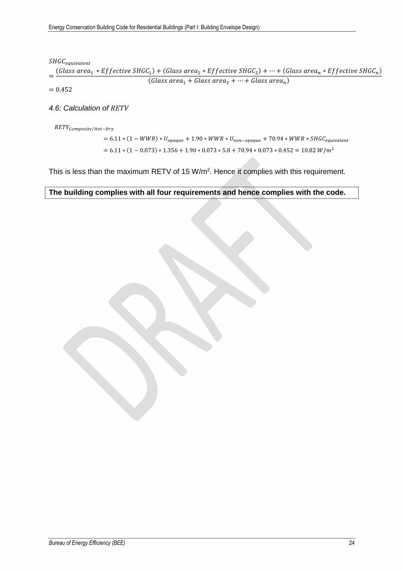
𝑆𝐻𝐺𝐶𝑒𝑞𝑢𝑖𝑣𝑎𝑙𝑒𝑛𝑡
=(𝐺𝑙𝑎𝑠𝑠 𝑎𝑟𝑒𝑎1 ∗ 𝐸𝑓𝑓𝑒𝑐𝑡𝑖𝑣𝑒 𝑆𝐻𝐺𝐶1) + (𝐺𝑙𝑎𝑠𝑠 𝑎𝑟𝑒𝑎2 ∗ 𝐸𝑓𝑓𝑒𝑐𝑡𝑖𝑣𝑒 𝑆𝐻𝐺𝐶2) + ⋯ + (𝐺𝑙𝑎𝑠𝑠 𝑎𝑟𝑒𝑎𝑛 ∗ 𝐸𝑓𝑓𝑒𝑐𝑡𝑖𝑣𝑒 𝑆𝐻𝐺𝐶𝑛)
(𝐺𝑙𝑎𝑠𝑠 𝑎𝑟𝑒𝑎1 + 𝐺𝑙𝑎𝑠𝑠 𝑎𝑟𝑒𝑎2 + ⋯ + 𝐺𝑙𝑎𝑠𝑠 𝑎𝑟𝑒𝑎𝑛)
= 0.452
4.6: Calculation of 𝑅𝐸𝑇𝑉
𝑅𝐸𝑇𝑉𝐶𝑜𝑚𝑝𝑜𝑠𝑖𝑡𝑒 𝐻𝑜𝑡⁄ −𝐷𝑟𝑦
= 6.11 ∗ (1 − 𝑊𝑊𝑅) ∗ 𝑈𝑜𝑝𝑎𝑞𝑢𝑒 + 1.90 ∗ 𝑊𝑊𝑅 ∗ 𝑈𝑛𝑜𝑛−𝑜𝑝𝑎𝑞𝑢𝑒 + 70.94 ∗ 𝑊𝑊𝑅 ∗ 𝑆𝐻𝐺𝐶𝑒𝑞𝑢𝑖𝑣𝑎𝑙𝑒𝑛𝑡
= 6.11 ∗ (1 − 0.073) ∗ 1.356 + 1.90 ∗ 0.073 ∗ 5.8 + 70.94 ∗ 0.073 ∗ 0.452 = 10.82 𝑊/𝑚2
This is less than the maximum RETV of 15 W/m2. Hence it complies with this requirement.
The building complies with all four requirements and hence complies with the code.
Energy Conservation Building Code for Residential Buildings (Part I: Building Envelope Design)
Bureau of Energy Efficiency (BEE) 25
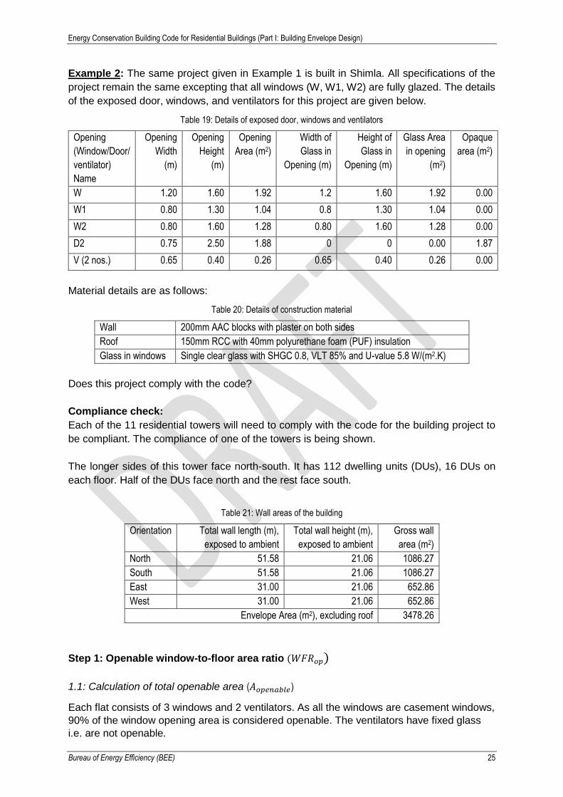
Example 2: The same project given in Example 1 is built in Shimla. All specifications of the
project remain the same excepting that all windows (W, W1, W2) are fully glazed. The details
of the exposed door, windows, and ventilators for this project are given below.
Table 19: Details of exposed door, windows and ventilators
Opening
(Window/Door/
ventilator)
Name
Opening
Width
(m)
Opening
Height
(m)
Opening
Area (m2)
Width of
Glass in
Opening (m)
Height of
Glass in
Opening (m)
Glass Area
in opening
(m2)
Opaque
area (m2)
W 1.20 1.60 1.92 1.2 1.60 1.92 0.00
W1 0.80 1.30 1.04 0.8 1.30 1.04 0.00
W2 0.80 1.60 1.28 0.80 1.60 1.28 0.00
D2 0.75 2.50 1.88 0 0 0.00 1.87
V (2 nos.) 0.65 0.40 0.26 0.65 0.40 0.26 0.00
Material details are as follows:
Table 20: Details of construction material
Wall 200mm AAC blocks with plaster on both sides
Roof 150mm RCC with 40mm polyurethane foam (PUF) insulation
Glass in windows Single clear glass with SHGC 0.8, VLT 85% and U-value 5.8 W/(m2.K)
Does this project comply with the code?
Compliance check:
Each of the 11 residential towers will need to comply with the code for the building project to
be compliant. The compliance of one of the towers is being shown.
The longer sides of this tower face north-south. It has 112 dwelling units (DUs), 16 DUs on
each floor. Half of the DUs face north and the rest face south.
Table 21: Wall areas of the building
Orientation Total wall length (m),
exposed to ambient
Total wall height (m),
exposed to ambient
Gross wall
area (m2)
North 51.58 21.06 1086.27
South 51.58 21.06 1086.27
East 31.00 21.06 652.86
West 31.00 21.06 652.86
Envelope Area (m2), excluding roof 3478.26
Step 1: Openable window-to-floor area ratio (𝑊𝐹𝑅𝑜𝑝)
1.1: Calculation of total openable area (𝐴𝑜𝑝𝑒𝑛𝑎𝑏𝑙𝑒)
Each flat consists of 3 windows and 2 ventilators. As all the windows are casement windows,
90% of the window opening area is considered openable. The ventilators have fixed glass
i.e. are not openable.
Energy Conservation Building Code for Residential Buildings (Part I: Building Envelope Design)
Bureau of Energy Efficiency (BEE) 26
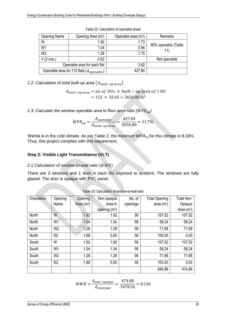
Table 22: Calculation of openable areas
Opening Name Opening Area (m2) Openable area (m2) Remarks
W 1.92 1.73 90% openable (Table
11) W1 1.04 0.94
W2 1.28 1.15
V (2 nos.) 0.52 Not openable
Openable area for each flat 3.82
Openable area for 112 flats (𝐴𝑜𝑝𝑒𝑛𝑎𝑏𝑙𝑒) 427.84
1.2: Calculation of total built-up area (𝐴𝑏𝑢𝑖𝑙𝑡−𝑢𝑝 𝑎𝑟𝑒𝑎)
𝐴𝑏𝑢𝑖𝑙𝑡−𝑢𝑝 𝑎𝑟𝑒𝑎 = 𝑛𝑜. 𝑜𝑓 𝐷𝑈𝑠 × 𝑏𝑢𝑖𝑙𝑡 − 𝑢𝑝 𝑎𝑟𝑒𝑎 𝑜𝑓 1 𝐷𝑈
= 112 × 32.65 = 3656.80 𝑚2
1.3: Calculate the window operable area to floor area ratio (𝑊𝐹𝑅𝑜𝑝)
𝑊𝐹𝑅𝑜𝑝 =𝐴𝑜𝑝𝑒𝑛𝑎𝑏𝑙𝑒
𝐴𝑏𝑢𝑖𝑙𝑡−𝑢𝑝 𝑎𝑟𝑒𝑎=
427.84
3656.80= 11.7%
Shimla is in the cold climate. As per Table 2, the minimum WFRop for this climate is 8.33%.
Thus, this project complies with this requirement.
Step 2: Visible Light Transmittance (VLT)
2.1 Calculation of window-to-wall ratio (𝑊𝑊𝑅)
There are 3 windows and 1 door in each DU exposed to ambient. The windows are fully
glazed. The door is opaque with PVC panel.
Table 23: Calculation of window-to-wall ratio
Orientation Opening
Name
Opening
Area (m2)
Non-opaque
Area in
opening (m2)
No. of
openings
Total Opening
area (m2)
Total Non-
Opaque
Area (m2)
North W 1.92 1.92 56 107.52 107.52
North W1 1.04 1.04 56 58.24 58.24
North W2 1.28 1.28 56 71.68 71.68
North D2 1.88 0.00 56 105.00 0.00
South W 1.92 1.92 56 107.52 107.52
South W1 1.04 1.04 56 58.24 58.24
South W2 1.28 1.28 56 71.68 71.68
South D2 1.88 0.00 56 105.00 0.00
684.88 474.88
𝑊𝑊𝑅 =𝐴𝑛𝑜𝑛−𝑜𝑝𝑎𝑞𝑢𝑒
𝐴𝑒𝑛𝑣𝑒𝑙𝑜𝑝𝑒=
474.88
3478.26= 0.136

Energy Conservation Building Code for Residential Buildings (Part I: Building Envelope Design)
Bureau of Energy Efficiency (BEE) 27
As per Table 3, the minimum VLT for WWR ≤ 20% is 75%. The glass used in this project has
a VLT of 85% (as per certified specification for the product). Thus, this project complies with
this requirement.
Step 3: Thermal transmittance of roof (𝑈𝑟𝑜𝑜𝑓)
3.1 Calculation of thermal transmittance of roof (𝑈𝑟𝑜𝑜𝑓)
The roof of this building is the same as that of Example 1, i.e., U𝑟𝑜𝑜𝑓 is 0.71 W/m2.K. This is
less than the maximum U𝑟𝑜𝑜𝑓 value of 1.2 W/m2.K. Hence it complies with this requirement.
Step 4: Thermal transmittance of building envelope (except roof) for cold climatic
zone (𝑼𝒆𝒏𝒗𝒆𝒍𝒐𝒑𝒆,𝒄𝒐𝒍𝒅)
Shimla is in the cold climate zone. Hence, thermal transmittance of the building envelope
(except roof) will be calculated.
4.1 Calculation of thermal transmittance of building envelope (𝑈𝑒𝑛𝑣𝑒𝑙𝑜𝑝𝑒,𝑐𝑜𝑙𝑑)
In this case, the U values of the wall (i.e. AAC block with 15mm plaster on both sides), the
opaque door component (i.e. PVC sheet) and the non-opaque components (glass used in
windows) needs to be averaged
𝑈𝑒𝑛𝑣𝑒𝑙𝑜𝑝𝑒,𝑐𝑜𝑙𝑑
=(𝑁𝑒𝑡 𝐴𝐴𝐶 𝑏𝑙𝑜𝑐𝑘 𝑤𝑎𝑙𝑙 𝑎𝑟𝑒𝑎 ∗ 𝑈 𝑣𝑎𝑙𝑢𝑒 𝑜𝑓 𝐴𝐴𝐶) + (𝑂𝑝𝑎𝑞𝑢𝑒 𝑑𝑜𝑜𝑟 𝑎𝑟𝑒𝑎 ∗ 𝑈 𝑣𝑎𝑙𝑢𝑒 𝑜𝑓 𝑃𝑉𝐶) + (𝑁𝑜𝑛 − 𝑜𝑝𝑎𝑞𝑢𝑒 𝑎𝑟𝑒𝑎 ∗ 𝑈 𝑣𝑎𝑙𝑢𝑒 𝑜𝑓 𝑔𝑙𝑎𝑠𝑠)
𝑁𝑒𝑡 𝐴𝐴𝐶 𝑏𝑙𝑜𝑐𝑘 𝑤𝑎𝑙𝑙 𝑎𝑟𝑒𝑎 + 𝑂𝑝𝑎𝑞𝑢𝑒 𝑤𝑖𝑛𝑑𝑜𝑤 𝑎𝑟𝑒𝑎 + 𝑁𝑜𝑛 − 𝑜𝑝𝑎𝑞𝑢𝑒 𝑎𝑟𝑒𝑎
=(2793.38 ∗ 0.7) + (210 ∗ 5.61) + (474.88 ∗ 5.8)
2793.38 + 210 + 474.88= 1.693 𝑊 𝑚2⁄ . 𝐾
Note:
• Net AAC block area = Envelope area - Total opening area
• Opaque window area= Total opening area - Total non-opaque area
• U value of AAC block and PVC sheet is calculated the same way as that shown for the
roof. Thermal conductivity of AAC block is 0.162 W/m.K and that of PVC is 0.19 W/m.K
• U value of the glass used is given as 5.8 W/m2.K (as per certified specification for the
product)
This is less than the maximum U𝑒𝑛𝑣𝑒𝑙𝑜𝑝𝑒,𝑐𝑜𝑙𝑑 value of 1.8 W/m2.K. Hence it complies with this
requirement.
The building complies with all four requirements and hence complies with the code.
Energy Conservation Building Code for Residential Buildings (Part I: Building Envelope Design)
Bureau of Energy Efficiency (BEE) 28
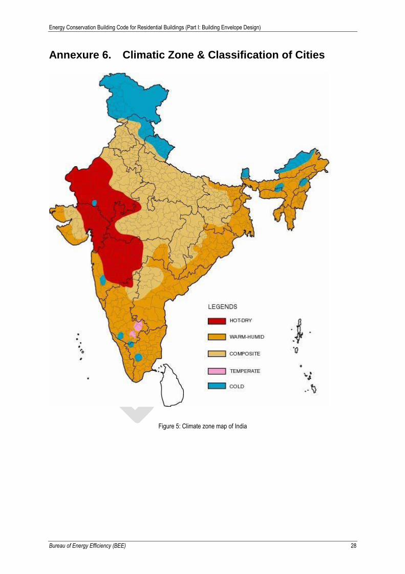
Annexure 6. Climatic Zone & Classification of Cities
Figure 5: Climate zone map of India

Energy Conservation Building Code for Residential Buildings (Part I: Building Envelope Design)
Bureau of Energy Efficiency (BEE) 29
Table 24: Climate Zone for Major Indian Cities
City Climate Type City Climate Type
Ahmedabad Hot & Dry Kurnool Warm & Humid
Allahabad Composite Leh Cold
Amritsar Composite Lucknow Composite
Aurangabad Hot & Dry Ludhiana Composite
Bangalore Temperate Chennai Warm & Humid
Barmer Hot & Dry Manali Cold
Belgaum Warm & Humid Mangalore Warm & Humid
Bhagalpur Warm & Humid Mumbai Warm & Humid
Bhopal Composite Nagpur Composite
Bhubaneshwar Warm & Humid Nellore Warm & Humid
Bikaner Hot & Dry New Delhi Composite
Chandigarh Composite Panjim Warm & Humid
Chitradurga Warm & Humid Patna Composite
Dehradun Composite Pune Warm & Humid
Dibrugarh Warm & Humid Raipur Composite
Guwahati Warm & Humid Rajkot Composite
Gorakhpur Composite Ramgundam Warm & Humid
Gwalior Composite Ranchi Composite
Hissar Composite Ratnagiri Warm & Humid
Hyderabad Composite Raxaul Warm & Humid
Imphal Warm & Humid Saharanpur Composite
Indore Composite Shillong Cold
Jabalpur Composite Sholapur Hot & Dry
Jagdelpur Warm & Humid Srinagar Cold
Jaipur Composite Sundernagar Cold
Jaisalmer Hot & Dry Surat Hot & Dry
Jalandhar Composite Tezpur Warm & Humid
Jamnagar Warm & Humid Tiruchirappalli Warm & Humid
Jodhpur Hot & Dry Trivandrum Warm & Humid
Jorhat Warm & Humid Tuticorin Warm & Humid
Kochi Warm & Humid Udhagamandalam Cold
Kolkata Warm & Humid Vadodara Hot & Dry
Kota Hot & Dry Veraval Warm & Humid
Kullu Cold Vishakhapatnam Warm & Humid
Energy Conservation Building Code for Residential Buildings (Part I: Building Envelope Design)
Bureau of Energy Efficiency (BEE) 30
Annexure 7. Terminology and Definitions
Building Envelope: The elements of a building that separate conditioned spaces from the
exterior or from unconditioned space.
Built-up area (for calculation of WFRop) of dwelling units: the covered area of all dwelling
units, including the area covered by walls, but excepting the balcony area.
Group housing: Building unit or units constructed or to be constructed with one or more floors having more than two dwelling units having common service facilities where land is shared and commonly used by the dwelling units, and the construction is undertaken by one agency. Non-opaque building envelope components: It includes transparent/translucent panels in
windows, doors, etc.
Opaque building envelope components: It includes wall, opaque panels in door and
window, etc.
Openable Window-to-Floor Ratio (WFR)op: The openable window-to-floor ratio (WFR)op is
the ratio of total openable area (addition of openable area of all windows and ventilators area,
excluding doors, opening directly to the external air or into an open balcony or “verandah”) to
the total built-up area of dwelling units (the covered area of all dwelling units, including the
area covered by walls, but excepting the balcony area).
Projection Factor, overhang: the ratio of the horizontal depth of the external shading
projection to the sum of the height of the fenestration and the distance from the top of the
fenestration to the bottom of the farthest point of the external shading projection, in consistent
units.
Projection Factor, side fin: the ratio of the horizontal depth of the external shading projection
to the distance from the window jamb to the farthest point of the external shading projection,
in consistent units.
Projection Factor, overhang and side fin: average of ratio projection factor for overhang
only and projection factor of side fin only.
RETV: Residential Envelope Heat Transmittance (𝑅𝐸𝑇𝑉) is the net heat gain rate (over the
cooling period) through building envelope (excluding roof) divided by the area of building
envelope (excluding roof). Its unit is W/m2.
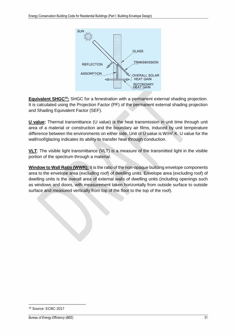
Solar Heat Gain Coefficient (SHGC)9: SHGC is the fraction of incident solar radiation
admitted through a fenestration, both directly transmitted, and absorbed and subsequently
released inward through conduction, convection and radiation.
SHGC =Transmission + Secondary heat gain
Incident solar radiation
9 Source: NBC 2016
Energy Conservation Building Code for Residential Buildings (Part I: Building Envelope Design)
Bureau of Energy Efficiency (BEE) 31
Equivalent SHGC10: SHGC for a fenestration with a permanent external shading projection.
It is calculated using the Projection Factor (PF) of the permanent external shading projection
and Shading Equivalent Factor (SEF).
U value: Thermal transmittance (U value) is the heat transmission in unit time through unit
area of a material or construction and the boundary air films, induced by unit temperature
difference between the environments on either side. Unit of U value is W/m2.K. U value for the
wall/roof/glazing indicates its ability to transfer heat through conduction.
VLT: The visible light transmittance (VLT) is a measure of the transmitted light in the visible
portion of the spectrum through a material.
Window to Wall Ratio (WWR): It is the ratio of the non-opaque building envelope components
area to the envelope area (excluding roof) of dwelling units. Envelope area (excluding roof) of
dwelling units is the overall area of external walls of dwelling units (including openings such
as windows and doors, with measurement taken horizontally from outside surface to outside
surface and measured vertically from top of the floor to the top of the roof).
10 Source: ECBC 2017

Energy Conservation Building Code for Residential Buildings (Part I: Building Envelope Design)
Bureau of Energy Efficiency (BEE) 32
Committees and Working Groups
Steering Committee (Participants)
Abhay Bakre, Director General, Bureau of Energy Efficiency (Chair)
Saurabh Diddi, Director, Bureau of Energy Efficiency (Convenor)
Arijit Sengupta, Bureau of Energy Efficiency
Madhurima Madhav, Bureau of Indian Standards (BIS)
Vijay Garg, Council of Architecture (COA)
V.P. Singh, Ministry of Housing and Urban Affairs
B.K. Bhatt, Ministry of New and Renewable Energy
R. Srinivas, Town and Country Planning Organisation (TCPO)
S. Surendra, Town and Country Planning Organisation (TCPO)
Pawan Kumar, Town and Country Planning Organisation (TCPO)
Anand Shukla, Swiss Agency for Development and Cooperation (SDC)
Abdullah Nisar Siddiqui, UNDP-GEF Project
Karl May, Deutsche Gesellschaft für Internationale Zusammenarbeit (GIZ)
S. Vikash Ranjan, Deutsche Gesellschaft für Internationale Zusammenarbeit (GIZ)
Govinda Somani, Deutsche Gesellschaft für Internationale Zusammenarbeit (GIZ)
Wesley Wojtas, Deutsche Gesellschaft für Internationale Zusammenarbeit (GIZ)
Apurva Chaturvedi, The United States Agency for International Development (USAID)
Naveen Akkina, Indian Green Building Council (IGBC)
Punit Agarwal, Indian Green Building Council (IGBC)
Mili Majumdar, Green Building Certification Inc (GBCI)
Apoorv Vij, Green Building Certification Inc (GBCI)
Suhaas Mathur, Green Building Certification Inc (GBCI)
Yatin Choudhary, The Energy and Resources Institute (TERI)
Pardeep Chauhan, The Energy and Resources Institute (TERI)
Disha Sharma, The Energy and Resources Institute (TERI)
Amor Kool, Kaleidoscope
Energy Conservation Building Code for Residential Buildings (Part I: Building Envelope Design)
Bureau of Energy Efficiency (BEE) 33
Ashok Lall, Ashok B. Lall Architects
Prashant Bhanware, Indo Swiss Building Energy Efficiency Project (BEEP)
Saswati Chetia, Indo Swiss Building Energy Efficiency Project (BEEP)
Vernica Prakash Kapoor, Indo Swiss Building Energy Efficiency Project (BEEP)
Sameer Maithel, Indo Swiss Building Energy Efficiency Project (BEEP)
Technical Committee (Participants)
Saurabh Diddi, Director, Bureau of Energy Efficiency (Chair & Convenor)
Arijit Sengupta, Bureau of Energy Efficiency (BEE)
Anju Singh, Bureau of Energy Efficiency (BEE)
Madhurima Madhav, Bureau of Indian Standards (BIS)
Ujjwal Mitra, Central Public Works Department (CPWD)
Rajeev Sharma, Central Public Works Department (CPWD)
R. Srinivas, Town and Country Planning Organisation (TCPO)
Harpal Dave, Town and Country Planning Organisation (TCPO)
Anand Shukla, Swiss Agency for Development and Cooperation (SDC)
Tanmay Tathagat, Environmental Design Solutions (EDS) Global (P) Ltd.
Piyush Varma, EDS Global (P) Ltd.
Ashok Lall, Ashok B. Lall Architects
Salil Mohan, Ashok B. Lall Architects
Rajan Rawal, Centre for Environmental Planning and Technology (CEPT) University, Ahmedabad
Vishal Garg, International Institute of Information Technology (IIIT), Hyderabad
Jyotirmay Mathur, Malaviya National Institute of Technology (MNIT), Jaipur
Shweta Manchanda, School of Planning and Architecture (SPA)
Abdullah Nisar Siddiqui, UNDP-GEF Project
Meenal Anand, UNDP- GEF Project
Karl May, Deutsche Gesellschaft für Internationale Zusammenarbeit (GIZ)
S. Vikash Ranjan, Deutsche Gesellschaft für Internationale Zusammenarbeit (GIZ)

Energy Conservation Building Code for Residential Buildings (Part I: Building Envelope Design)
Bureau of Energy Efficiency (BEE) 34
Govinda Somani, Deutsche Gesellschaft für Internationale Zusammenarbeit (GIZ)
Naveen Akkina, Indian Green Building Council (IGBC)
Shivraj Dhaka, Indian Green Building Council (IGBC)
Praveen Soma, Indian Green Building Council (IGBC)
Apoorv Vij, Green Building Certification Inc (GBCI)
Suhaas Mathur, Green Building Certification Inc (GBCI
Yatin Choudhary, The Energy and Resources Institute (TERI)
Pradeep Kumar, The Energy and Resources Institute (TERI)
G.N. Gohul Deepak, Glazing Society of India (GSI)
R. Subramanian, Glazing Society of India (GSI)
Murali N., Glazing Society of India (GSI)
S. Senthil Kumar, The All India Glass Manufacturers' Federation (AIGMF)
Aditi Salway, The All India Glass Manufacturers' Federation (AIGMF)
Isaac Emmanuel, Indian Insulation Forum (IIF)
Rohit Jain, Indian Institute of Architects (IIA)
Pierre Jaboyedoff, Indo-Swiss Building Energy Efficiency Project (BEEP)
Prashant Bhanware, Indo-Swiss Building Energy Efficiency Project (BEEP)
Saswati Chetia, Indo-Swiss Building Energy Efficiency Project (BEEP)
Vernica Prakash Kapoor, Indo-Swiss Building Energy Efficiency Project (BEEP)
Sameer Maithel, Indo-Swiss Building Energy Efficiency Project (BEEP)
Development Team
Bureau of Energy Efficiency
Saurabh Diddi
Arijit Sengupta
Anju Singh
Swiss Agency for Development and Cooperation
Anand Shukla

Energy Conservation Building Code for Residential Buildings (Part I: Building Envelope Design)
Bureau of Energy Efficiency (BEE) 35
Indo-Swiss Building Energy Efficiency Project
Pierre Jaboyedoff, Effin’art Sarl
Sameer Maithel, Greentech Knowledge Solutions Pvt. Ltd.
Prashant Bhanware, Greentech Knowledge Solutions Pvt. Ltd.
Ashok Lall, Ashok B. Lall Architects
Salil Mohan, Ashok B. Lall Architects
Saswati Chetia, Greentech Knowledge Solutions Pvt. Ltd.
Vernica Prakash Kapoor, Greentech Knowledge Solutions Pvt. Ltd.
Satyendra Rana, Greentech Knowledge Solutions Pvt. Ltd.