energy boot camp for builders - national center for ...€¦ · energy boot camp for builders ......
TRANSCRIPT

NCAT NCAT
1
Energy Boot Camp for Builders
December 2013 Presented by Dale Horton, Architect National Center for Appropriate Technology
Building Science and Changes to the Montana Energy Code
New Construction PTCS Duct Sealing & Blower Door Training
NCAT
2
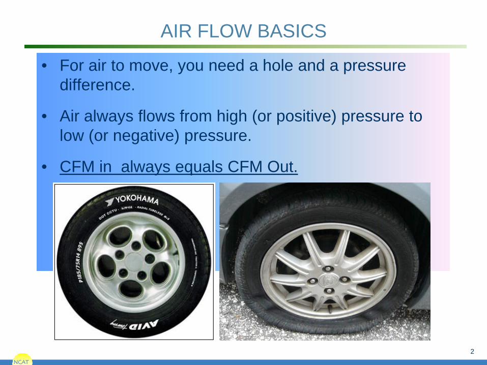
AIR FLOW BASICS
• For air to move, you need a hole and a pressure difference.
• Air always flows from high (or positive) pressure to low (or negative) pressure.
• CFM in always equals CFM Out.

NCAT
What Is Pressure?

NCAT
A Simple Manometer

NCAT
A Simple Manometer

NCAT
Examples of House Pressure Measurements
• Wind (Ave. 4 Pa) • Stack Effect (1-3 Pa) • Furnace plenum (120 Pa) • Boot (5 Pa) • Flue (-3 Pa) • Bedroom with doors closed (up to 10 Pa) • Room with a big exhaust fan (-20 Pa) • House pressurized by blower door (50 Pa) • Potential Back Draft Problems (-3 Pa)
Source: PTCS 6

NCAT NCAT
7
Duct Blaster
Pressure Pan
Exhaust Flow Hood
Blower Door Fan
Digital Manometer
Blower Door Frame
Typical Performance Testing Equipment

NCAT
There are several different types of manometers: • Energy Conservatory DG 700 • Retrotec DM-2 • Infiltec DM-4
For PTCS trainings, we use Energy Conservatory Equipment
The Manometer

NCAT NCAT
9
Key references for the discussion of performance testing are available on the web at:
• Blower Door Operation Manual
• Quick Guide #DEP700-CR - 1 Point Depress Test with DG-700
• Duct Blaster Operation Manual
• Quick Guide #PR700-CR - 1 Point Total Leakage Press Test with DG-700
• Quick Guide #PR700 (Outside) - 1 Point Leakage to Outside Press Test with DG-700
Energy Conservatory

NCAT
Measures the pressure difference between two areas.
Input = 1st area
Reference = 2nd area
The Digital Manometer

NCAT
The DG-700 manometer also has 2 channels:
The Digital Manometer
Channel A
Channel B

NCAT
The Manometer Mantra:
(“Input Nipple”) with reference to (“Ref Nipple”)
(WRT)
The Digital Manometer
Input
NCAT NCAT
13
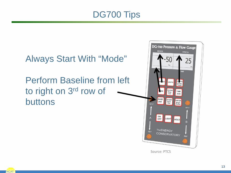
DG700 Tips
Always Start With “Mode” Perform Baseline from left to right on 3rd row of buttons
Source: PTCS

NCAT
• Displays the difference in pressure between the input and the reference.
• Does not display the difference in pressure between channels.
The Digital Manometer

NCAT
DEVICE CONFIG
MODE
Configuring the Manometer
CONFIG DEVICE
Tells manometer what measurements to display
(e.g pressure or flow)
Tells manometer what equipment is being used
Tells manometer what the equipment configuration is
(ring number) CONFIG
MODE
MODE
DEVICE

NCAT
Configuring the Manometer - MODE
Mode
Measures the pressure difference between “input” and reference on both channels A and B
Measures the amount pressure recorded on channel A, and the amount of air flowing
through device on channel B
Calculates the amount of air that would flow through device on channel B if pressure on
channel A was 50 Pa. (for homes only)
Calculates the amount of air that would flow through device on channel B if pressure on
channel A was 25 Pa. (for ducts)
PR/PR
PR/FL
PR/FL@50
PR/FL@25
Tell it what you want to read

NCAT
Configuring the Manometer - Device
Device
Blower Door Model 3
Duct Blaster Model A (White Fan)
Duct Blaster Model B (Black Fan)
TrueFlow Plate and other Energy Conservatory Equipment.
BD3
DB A
DB B
TF, EXH, BD4, etc.
Tell it what you’re connected to

NCAT
Configuring the Manometer - Config
Open fan, no ring attached
Ring A (Blower door); Ring 1 (Duct Blaster)
Ring B (Blower Door); Ring 2 (Duct Blaster)
Ring C (Blower Door); Ring 3 (Duct Blaster)
Config Tell it how big the hole is (what
ring)
Open
A1
B2
C3

NCAT NCAT
19
List of Performance Tests in Action Order
1. Dominant Duct Leakage Test 2. Room Zonal Pressure Difference Test 3. Combustion Appliance Zone Test 4. Blower Door Test* 5. Zonal & Pressure Pan Tests w/ BD fan 6. Total Duct Leakage Test* 7. Duct Leakage to the Outside Test* 8. Exhaust Fan Flow Test * - Indicates test related to code

NCAT
PTCS Performance Tested
Comfort Systems
PTCS Duct Training – New Construction
Dominant Duct Leakage Not a Code Required Test

NCAT

NCAT

NCAT
PTCS Performance Tested
Comfort Systems
PTCS Duct Training – New Construction
Room Zonal Pressure Difference
Not a Code Required Test

NCAT NCAT
24
The NWESH program requires that the pressure between bedrooms and common area be tested to assure that the pressure difference in no more than 3 Pa.
Room Zonal Pressure Test

NCAT
25
Zonal Pressure Test
Measure pressure difference between room and central zone of home. What is the pressure in the room WRT the central zone?
+ +
-

NCAT
PTCS Performance Tested
Comfort Systems
PTCS Duct Training – New Construction
Combustion Appliance Zone Test
Not a Code Required Test

NCAT
What’ A CAZ?
Any zone in the house , including the garage, that contains a vented combustion appliance

NCAT
Causes of CO in Homes
• Urban Traffic • Cars started in garages • Unvented combustion equipment • Backdrafting combustion equipment • Failed heat exchangers • Really dumb stuff (barbecuing indoors, running generators
indoors etc • If there is Combustion there might be CO

NCAT NCAT
Carbon Monoxide (CO)

NCAT
Carbon Monoxide (CO)

NCAT
Unvented Combustion Equipment - Not Safe
NCAT NCAT
32
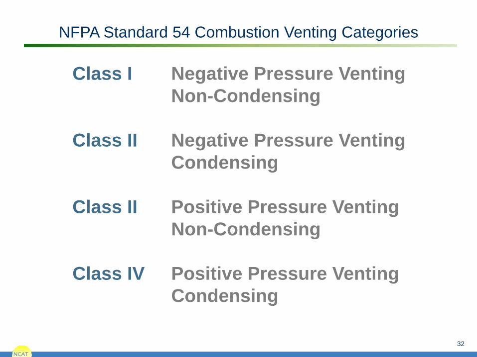
NFPA Standard 54 Combustion Venting Categories
Class I Negative Pressure Venting Non-Condensing Class II Negative Pressure Venting Condensing Class II Positive Pressure Venting Non-Condensing Class IV Positive Pressure Venting Condensing

NCAT
Why Category I Appliances Vent

NCAT
The Driving Forces That Change Air Pressure in a House
• Wind • Stack (the Chimney effect) • Exhaust Fans • Duct leakage • Unbalanced forced air systems (interior door closure)

NCAT
Stack Effect: The most persistent consistent pressure effect.
Positive Pressure
Negative Pressure
Neutral Pressure Plane
35

NCAT NCAT
Exfiltration
Infiltration
Wind creates positive and negative pressures within the house.
Wind Driven Pressures
36
Negative Pressure
Positive Pressure
Wind Direction

NCAT NCAT
The Two Paths of Air in a Furnace House Air
Combustion Air
The HVAC fan is the driving force that moves the air in the house air path
Buoyancy is the driving force that moves the air in the combustion air path

NCAT NCAT
Correct Venting, Gas water Heater Venting Successfully

NCAT NCAT
Large Kitchen Fan Backdrafting Gas Water Heater

NCAT
Good Venting

NCAT
Bad Venting = Backdrafting
NCAT
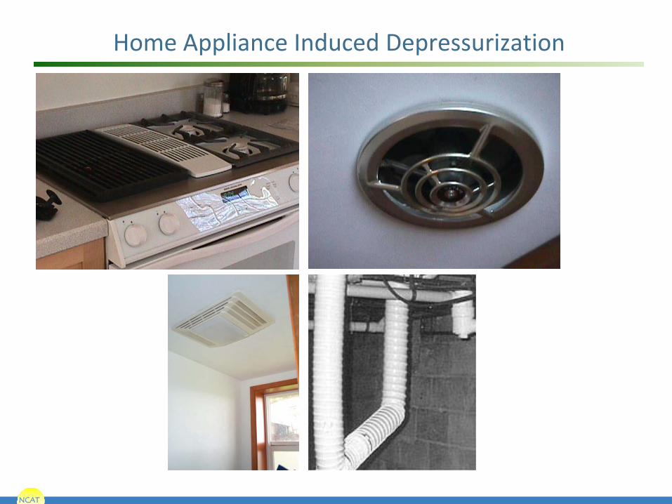
Home Appliance Induced Depressurization

NCAT
Beware of Over Sized Fans
• Tim Allen “More Power” Kitchen fans are sometimes rated at 1,200 CFM.
• Installed in a commercial environment, code would require make up air.
NCAT NCAT
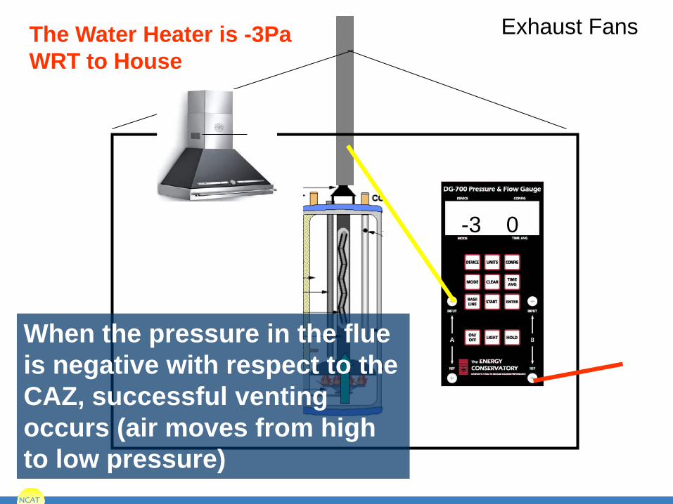
-3 0
The Water Heater is -3Pa WRT to House
Exhaust Fans
When the pressure in the flue is negative with respect to the CAZ, successful venting occurs (air moves from high to low pressure)

NCAT NCAT
+3 -5
Large Kitchen Fan Backdrafting Gas Water Heater
When the pressure in the flue is positive with respect to the CAZ backdrafting occurs. (air moves from high to low pressure)

NCAT NCAT
-4 +5
SUPPLY LEAK INSIDE HOUSE
Supply Leak Pressurized CAZ
NCAT NCAT
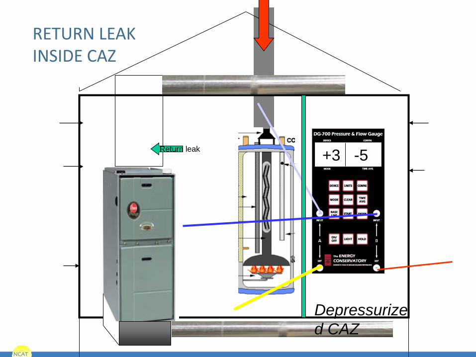
+3 -5
RETURN LEAK INSIDE CAZ
Return leak
Depressurized CAZ
NCAT NCAT
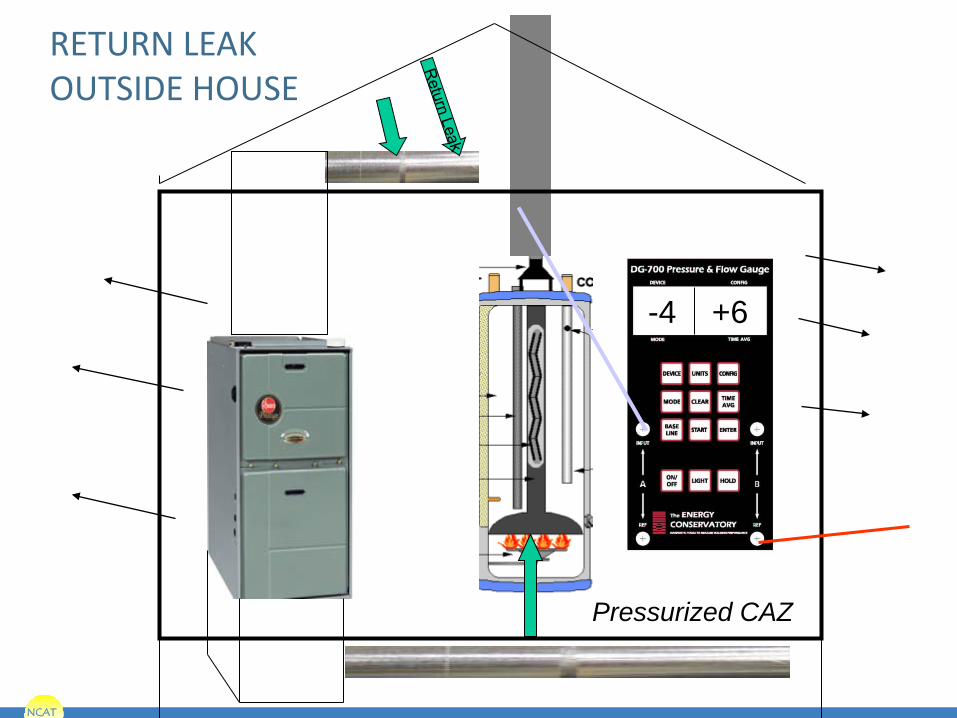
-4 +6
RETURN LEAK OUTSIDE HOUSE
Pressurized CAZ

NCAT NCAT
+4 -6
SUPPLY LEAK OUTSIDE HOUSE
Depressurized CAZ

NCAT
CAZ Test

NCAT
51
Setting Up the CAZ Test
If zone behind closed door is Positive WRT CAZ Leave door closed Negative WRT CAZ Open door
+ CAZ
+
- CAZ
-

NCAT
Fixing The Problem
• Make more holes in the house
• Push more air into the house
• Suck more air out of the venting system
• Get rid of the back drafting appliance
• Get rid of the source of depressurization

NCAT
Removing the Source of Depressurization
• Seal holes in top of building
• Seal return duct leaks in the CAZ
• Seal supply leaks outside the envelope of the house
• Eliminate high speed on oversized kitchen fans

NCAT NCAT
54
Baseline in CAZ -3 Pa Adjusted Air Handler On -4 Pa -1 Pa Basement Bath Fan -6 Pa -3 Pa 1st Floor Bath Fan -8 Pa -5 Pa Kitchen Fan -14.5 Pa -11.5 Pa 2nd Floor Bath Fan -17 Pa -14 Pa Clothes Dryer -19 Pa -16 Pa
Combustion Appliance Zone Pressure Test Example
NCAT NCAT
55
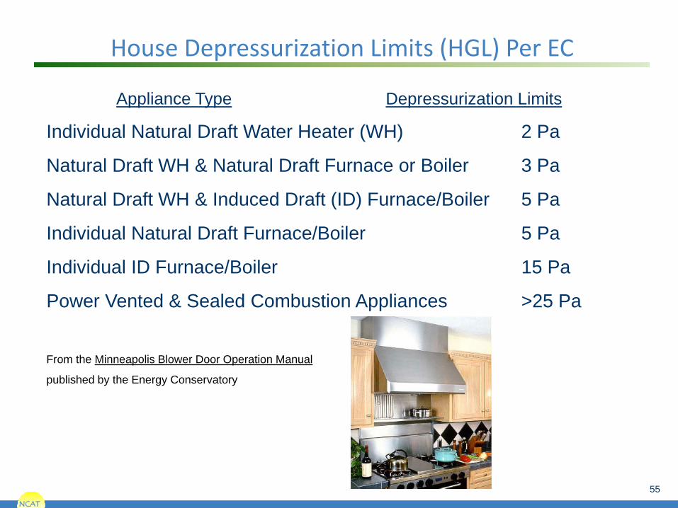
Appliance Type Depressurization Limits
Individual Natural Draft Water Heater (WH) 2 Pa
Natural Draft WH & Natural Draft Furnace or Boiler 3 Pa
Natural Draft WH & Induced Draft (ID) Furnace/Boiler 5 Pa
Individual Natural Draft Furnace/Boiler 5 Pa
Individual ID Furnace/Boiler 15 Pa
Power Vented & Sealed Combustion Appliances >25 Pa
From the Minneapolis Blower Door Operation Manual
published by the Energy Conservatory
House Depressurization Limits (HGL) Per EC

NCAT
PTCS Performance Tested
Comfort Systems
PTCS Duct Training – New Construction
Blower Door Test
A Code Required Test (for all homes)

NCAT
Blower Door Measure how much air leaks through cracks and ducts
If the fan is blowing 2,000 cfm out of the house, and it’s staying at the same pressure (-50 Pa), there must be 2,000 cfm of air leaking through holes in the house
Source: PTCS 57
The Blower Door

NCAT NCAT
58
Typical House Tightness Levels
Example based on 2,000 Ft2 house with n = 14.5.
CFM ACH50 2000 SF Older Homes 10+ >2600 Typical New Home ~2000 7 1800 2009 IECC Tightness Limit Zone 6 7 1800 Montana State Energy Code 4 1050 Proposed MT State Energy Code 4 1050 Energy Star Homes 4 1050 Idaho New Homes 2013 3.6 930 2012 IECC Tightness Limit Zone 6 3 800

NCAT
The Blower Door Parts - Rings
Fan (no ring=open config)
Ring B
Ring A
Fan Cover
NCAT
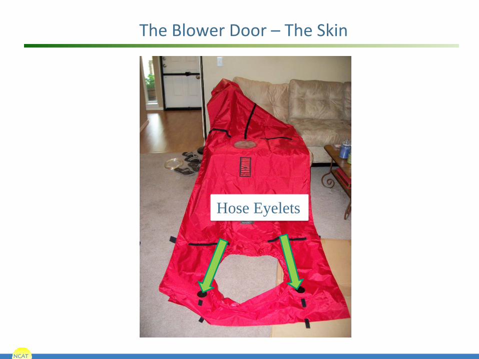
The Blower Door – The Skin
Hose Eyelets

NCAT
Blower Door Parts – the Pressure Sensor Ring
Pressure sensor on front side of fan
Manometer measures pressure difference
The higher the pressure drop, the bigger the flow
Given the same configuration (ring size) the higher the pressure, the bigger the flow
Higher Pressure = More Flow

NCAT
The Measurement

NCAT
Pressurizing the House
Pressure x hole size = flow
The larger the opening, the greater the flow.

NCAT
Safety Mandates 1. Do not use the blower door
if you see one of these! • Fire (Pressurize the
home = blast furnace) • Ash (Depressurize the
home = ashes spread) 2. All gas appliances
(combustion furnaces and water heaters) must be off (set it to pilot)
3. House should be inspected for potential asbestos contamination

NCAT
Blower Door

NCAT NCAT
66
One-point and Multi-point Blower Door Test Procedures (assumes DG-700)
Perform baseline measurement (with fan sealed) Choose and install appropriate flow ring Select Device in DG-700 (i.e., BD-3) Select flow ring configuration in DG-700 (i.e., A1) For One-point Test choose a mode setting of PR/FL@50, increase fan speed until channel A is to within 5 Pa of 50, Channel B will display the one-point leakage estimate.
For Multi-point test take readings such as 60, 50, 40, 30 Pa, use Tectite software to correlate data, use during windy periods or if greater accuracy is desired.
NCAT NCAT
67
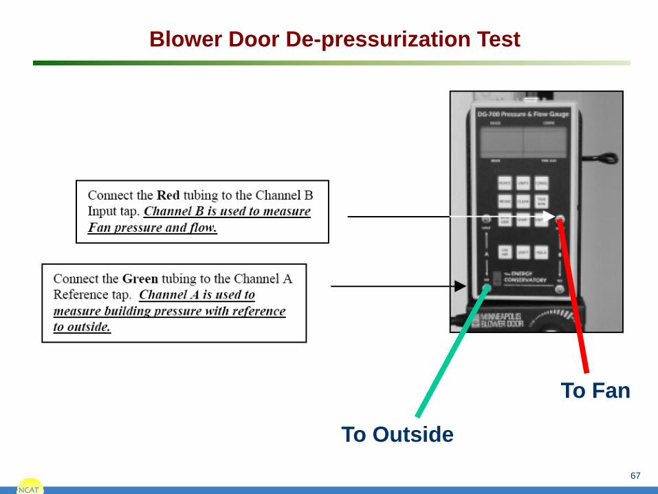
Blower Door De-pressurization Test
To Fan
To Outside

NCAT NCAT
68
Can’t Reach Fifty Factor
For DG-700 users, adjustment is made automatically if performing a one point test in PR/FL@50 mode
For DG-3 users if you can’t depressurize house to 50 Pa with an open fan then adjust measured air flow with CRF
Example: House can only be depressurized to 28 Pa with measured fan flow of 5,600 CFM.
CRF = 1.46 so adjusted flow is
5,600 x 1.46 = 8,176 CFM

NCAT NCAT
69
Blower Door Math
To calculate air changes per hour at 50 Pa:
ACH50 =
To convert air change rate at 50 Pa to the air change rate at natural conditions:
ACHnat =
n – The correlation factor shown on the following slide.
CFM50 x 60
House Volume
CFM50 x 60
n x House Volume
The volume is cubic feet enclosed by the conditioned space boundary.

NCAT NCAT
70
Converting CFM50 to Air Change Values (Provides Approximate Values)

NCAT NCAT
71
House Air Leakage Area Estimates 1. Divide CFM50 by 10 to get square inches of
leakage area. (Simple but approximate)
2. Use TECTITETM software from the Energy Conservatory with multi-point blower door test.
An alternative means of quantifying building tightness is to estimate the leakage area associated with a specific air flow.
Leakage Area Estimates

NCAT
PTCS Performance Tested
Comfort Systems
PTCS Duct Training – New Construction
Zonal and Pressure Pan Test w/ BD Fan
Not a Code Required Test

NCAT NCAT
Zone Pressure Testing
Set Up: Set up house for basic blower door test.

NCAT NCAT
Zone Pressure Testing

NCAT NCAT
Read Zone Pressure
Example: This Air handler (AH) is totally outside the conditioned area of the house.

NCAT
House WRT outside
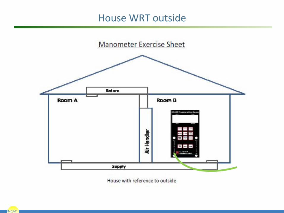
NCAT
House WRT outside

NCAT
House WRT Attic

NCAT
House WRT Attic

NCAT
Room A wrt Room B

NCAT
Supply ducts wrt house

NCAT
House wrt attic

NCAT
Room A WRT Room B

NCAT
Room A WRT Room B
NCAT NCAT
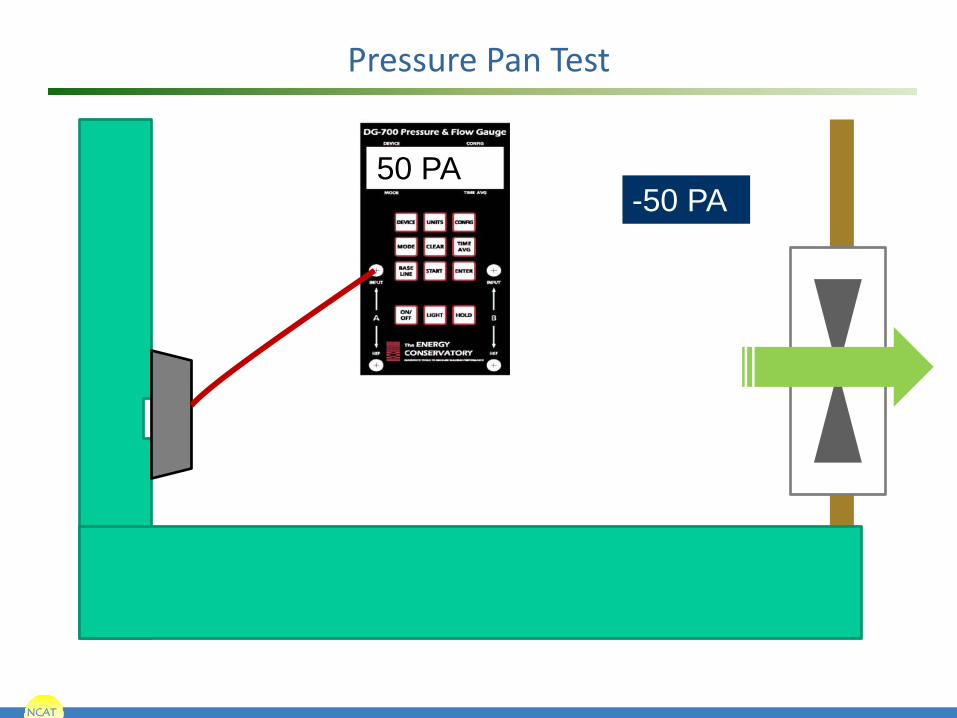
Pressure Pan Test
-50 PA 50 PA

NCAT NCAT
Pressure Pan Test
-50 PA 45 PA

NCAT NCAT
Pressure Pan Test
-50 PA 5 PA

NCAT NCAT
Pressure Pan Test
-50 PA 25 PA

NCAT
PTCS Performance Tested
Comfort Systems
PTCS Duct Training – New Construction
Total Duct Leakage
A Code Required Test (for some homes)

NCAT
Duct Blaster Parts
The Snorkel
The Rings The Fan

NCAT
Flow = Pressure x Size of Hole
You control the pressure with the fan speed controller. The rings change the size of the hole.
NCAT
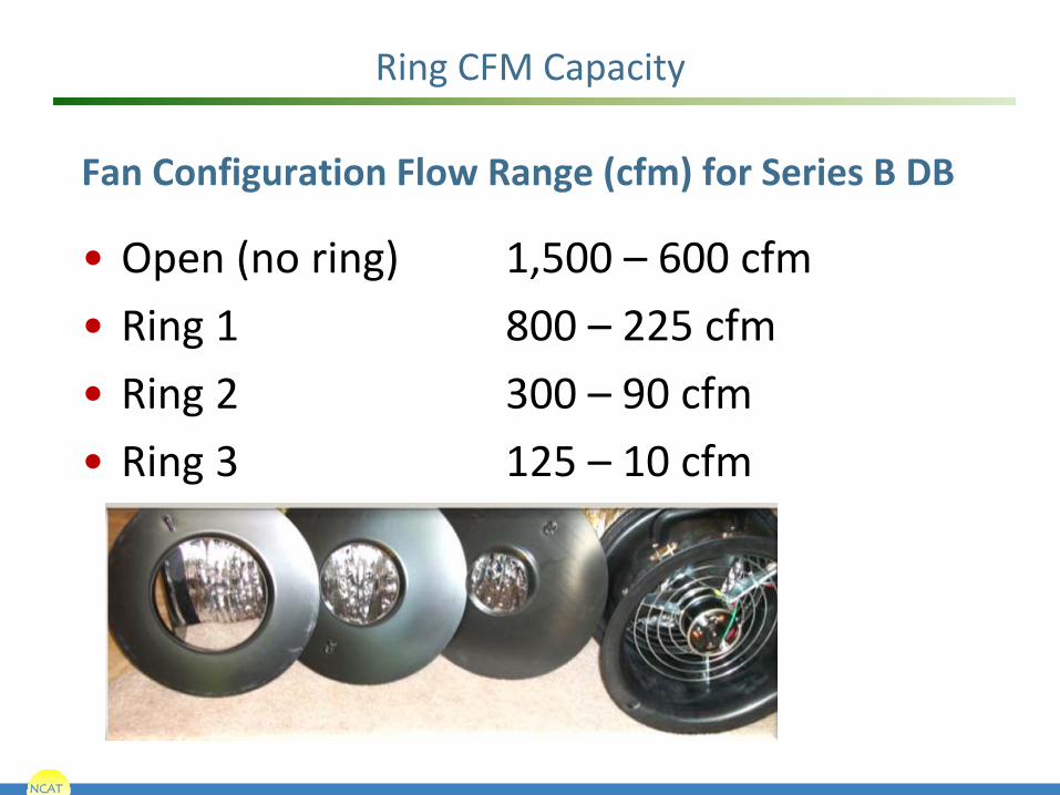
Ring CFM Capacity
Fan Configuration Flow Range (cfm) for Series B DB
• Open (no ring) 1,500 – 600 cfm • Ring 1 800 – 225 cfm • Ring 2 300 – 90 cfm • Ring 3 125 – 10 cfm

NCAT
Total Duct Leakage Test
Duct blaster blows air into duct system (increases
pressure)
Air blows out the leaks in the
system (registers are blocked)
Air blowing in has to be blowing out (leaks)

NCAT NCAT
Total Duct Leakage Test

NCAT
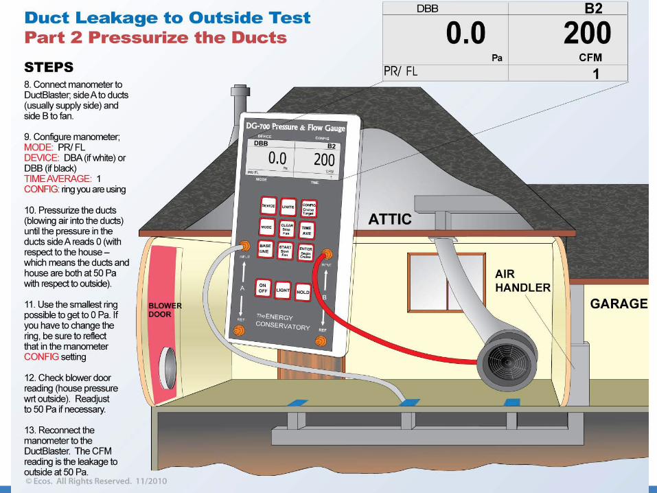
Total Duct Leakage Set Up
• Side A measures duct pressure
• Side B measures fan pressure, and manometer reflects it as CFM

NCAT
Attaching to the Return Grille

NCAT
Attaching to the Air Handler

NCAT
Direct Attachment to the Air handler
NCAT
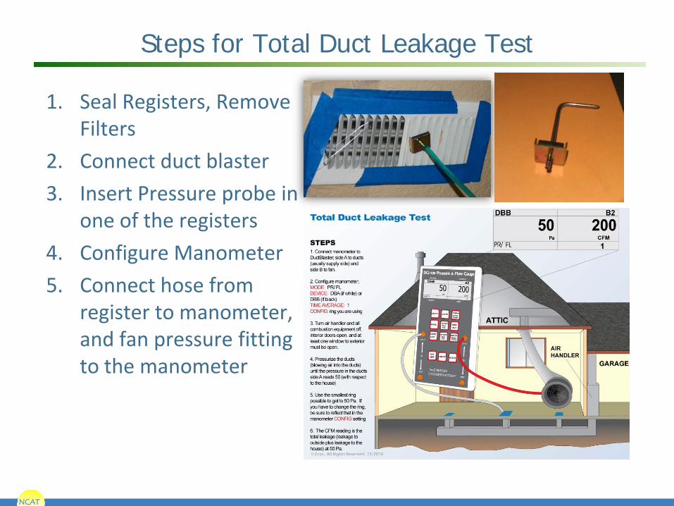
Steps for Total Duct Leakage Test
1. Seal Registers, Remove Filters
2. Connect duct blaster 3. Insert Pressure probe in
one of the registers 4. Configure Manometer 5. Connect hose from
register to manometer, and fan pressure fitting to the manometer

NCAT NCAT
Total Duct Leakage Test

NCAT NCAT
PTCS Total Duct Leakage Test

NCAT NCAT
Can’t Reach Pressure (CRP) Correction Factors
Example: The results of the test show a leakage area of 275 CFM at a duct pressure of 35 Pa. The correction factor for a pressure of 35 Pa is 1.26.
275 CFM35 X 1.26 = 346.5 CFM50
The test doesn’t give any indication of where to find the holes, just an estimate of the collected hole size. As CFM50 values get larger, they will tend to be less accurate.
Can’t Reach Pressure (CRP) Correction Factors Reference CRP Factor Pressure 50 PA 10 2.85 15 2.19 20 1.81 25 1.57 30 1.39 35 1.26 40 1.16 45 1.07

NCAT NCAT
Interpreting Results: The CFM50 is a measure of the total collected hole size in the system. As an approximation the CFM50 divided by 10 gives the total effective leakage area in square inches. Example: 400 CFM50/10 = 40 square inches of total leakage area. Using this approximation during sealing can help estimate how many and how big the holes are that you are looking to seal.
Total Duct Leakage Test

NCAT
PTCS Performance Tested
Comfort Systems
PTCS Duct Training – New Construction
Duct Leakage to the Outside
A Code Required Test (for certain homes)

NCAT NCAT
Duct Leakage to the Exterior
Standard New Construction: For certification, the measured CFM50 must not exceed 0.06 CFM50 x floor area served by the system (in square feet) or 75 CFM50 whichever is greater.
Source: NCAT

NCAT
NCAT

NCAT NCAT
108
Long or crimped exhaust fan ducts can significantly reduce actual exhaust flow.
Exhaust Fan Flow Test
Not a Code Required Test

NCAT
109
PTCS New Construction Duct Leakage Limits
Allowable Leakage = 0.06 CFM50 x conditioned floor area or 75 CFM50, whichever is greater. Example 1: What is the duct leakage limit for a 1000 SF house? 0.06 CFM50 x 1000 SF = 60 CFM, but since 75 CFM50 is greater the allowable leakage is 75 CFM50 Example 2: What is the duct leakage limit for a 3000 SF house? 0.06 CFM50 x 3000 SF = 180 CFM which is greater than 75 CFM so the allowable leakage is180 CFM

NCAT NCAT
110
PTCS Minimum Ventilation Level
MVL Based on known occupancy: MVL = (# of occupants) x (15 cfm/occupant) MVL Based on bedrooms: MVL = (3 of bedrooms + 1) x (15 cfm/bedroom) MVL Based on ACH and Volume MVL = (0.35 ACHnat x House Volume in ft3) / 60 minutes
Most Restrictive Should be Applied.