endeavor series on-line ups user's manual€¦ · endeavor series para systems, inc. 1455...
TRANSCRIPT

User's Manual
Endeavor Series
Para Systems, Inc.1455 Lemay Dr.
Carrollton, TX 75007Phone: 1-972-446-7363
Fax: 1-972-446-9011Internet: minutemanups.comUPS Sizing: sizemyups.com
PN - 34000274
On-Line UPS

1
© Copyright 2006
1. Introduction 2
2. Controls and Indicators 6
3. Installation 9
4. Operation 15
5. Troubleshooting 18
6. Replacing the Battery 19
7. Obtaining Service 22
8. Specifications 23
9. Configurable Parameters & Settings 25
10. Limited Product Warranty 26
A1. Declaration of Conformity 28
Eng
lish
2 3
IMPORTANT SAFETY INSTRUCTIONSSAVE THESE INSTRUCTIONS !
WARNING: Risk of Electrical Shock. Hazardous live parts insidethese power supplies are energized from the battery even when theAC input is disconnected.
CAUTION! To de-energize the outputs of the UPS:1. If the UPS is on press and release the Off button. NOTE: For the
208V models; turn the input circuit breaker to the off position.2. Disconnect the UPS from the AC wall outlet.3. To de-energize the UPS completely, disconnect the battery.
CAUTION! To reduce the risk of electrical shock in conditionswhere the load equipment grounding cannot be verified, disconnectthe UPS from the AC wall outlet before installing a computer interfacecable. Reconnect the power cord only after all signaling connectionsare made.
CAUTION! Connect the UPS to a two pole, three wire groundingAC wall outlet. The receptacle must be connected to the appropriatebranch protection (circuit breaker or fuse). Connection to any othertype of receptacle may result in a shock hazard and violate localelectrical codes. Do not use extension cords, adapter plugs, or surgestrips.
Eng
lish
English
Thank you for purchasing this power protection product. It has been designedand manufactured to provide many years of trouble free service.
Please read this manual before installing your Endeavor On-Line Series UPS,models ED1000RM2U, ED1000RMT2U, ED1500RM2U, ED1500RMT2U,ED2000RM2U, ED2000RMT2U, ED3000RM2U, ED3000RMT2U as it providesimportant information that should be followed during installation and mainte-nance of the UPS and batteries allowing you to correctly set up your system forthe maximum safety and performance. Included is information on customersupport and factory service if it is required. If you experience a problem with theUPS please refer to the Troubleshooting guide in this manual to correct theproblem or collect enough information so that the Technical Support Depart-ment can rapidly assist you.
CAUTION! To reduce the risk of electrical shock with the installa-tion of this UPS equipment and the connected equipment, the usermust ensure that the combined sum of the AC leakage current doesnot exceed 3.5mA.
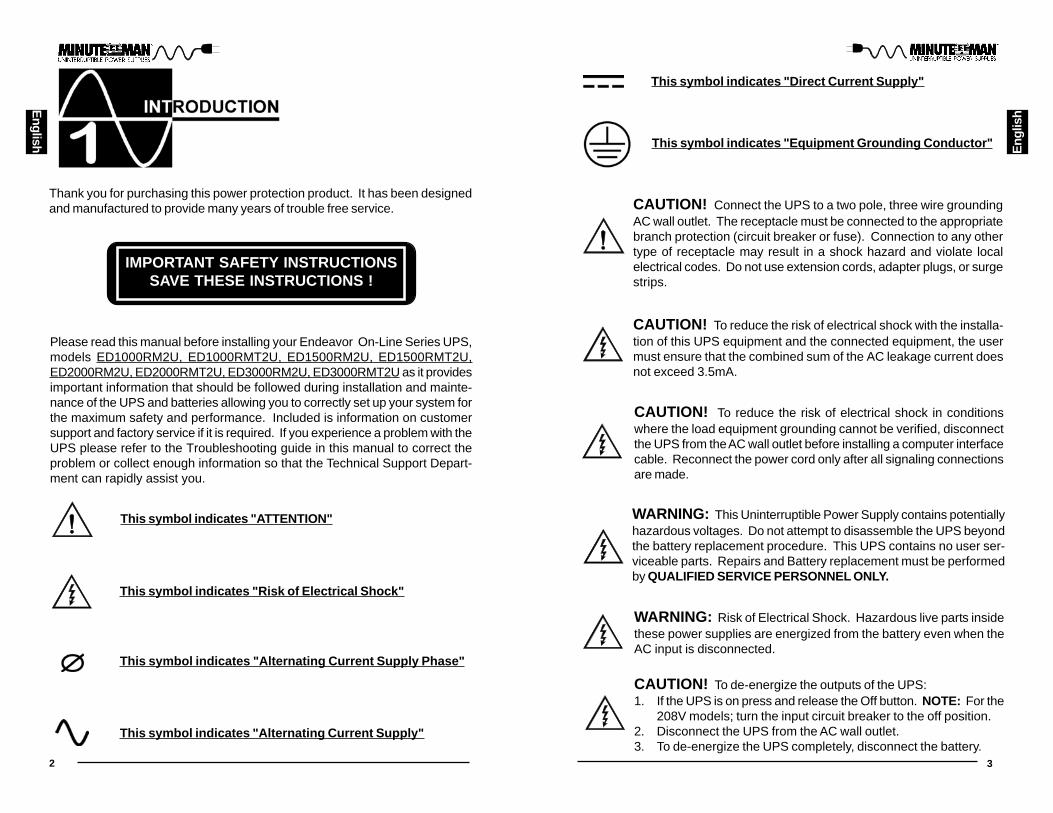
This symbol indicates "ATTENTION"
This symbol indicates "Risk of Electrical Shock"
This symbol indicates "Alternating Current Supply"
This symbol indicates "Direct Current Supply"
This symbol indicates "Alternating Current Supply Phase"
This symbol indicates "Equipment Grounding Conductor"
WARNING: This Uninterruptible Power Supply contains potentiallyhazardous voltages. Do not attempt to disassemble the UPS beyondthe battery replacement procedure. This UPS contains no user ser-viceable parts. Repairs and Battery replacement must be performedby QUALIFIED SERVICE PERSONNEL ONLY.

4 5
Eng
lish
English
Life Support Policy
As a general policy, we do not recommend the use of any of our products in lifesupport applications where failure or malfunction of the product can be reason-ably expected to cause failure of the life support device or to significantly affectits safety or effectiveness. We do not recommend the use of any of our prod-ucts in direct patient care. We will not knowingly sell our products for use insuch applications unless it receives in writing assurances satisfactory to usthat (a) the risks of injury or damage have been minimized, (b) the customerassumes all such risks, and (c) our liability is adequately protected under thecircumstances.
Examples of devices considered to be life support devices are neonatal oxygenanalyzers, nerve stimulators (whether used for anesthesia, pain relief, or otherpurposes), auto transfusion devices, blood pumps, defibrillators, arrhythmiadetectors and alarms, pacemakers, hemodialysis systems, peritoneal dialysissystems, neonatal ventilator incubators, ventilators for both adults and infants,anesthesia ventilators, and infusion pumps as well as any other devices desig-nated as “critical” by the United States FDA.
Hospital grade wiring devices and leakage current may be ordered as optionson many of our UPS systems. We do not claim that units with this modificationare certified or listed as Hospital Grade by us or any other organization. There-fore, these units do not meet the requirements for use in direct patient care.After removing your UPS from its carton, it should be inspected for damage that
may have occurred in shipping. Immediately notify the carrier and place ofpurchase if any damage is found. Warranty claims for damage caused by thecarrier will not be honored. The packing materials that your UPS was shippedin are carefully designed to minimize any shipping damage. In the unlikelycase that the UPS needs to be returned to the manufacturer, please use theoriginal packing material. Since the manufacturer is not responsible for ship-ping damage incurred when the system is returned, the original packing mate-rial is inexpensive insurance. PLEASE SAVE THE PACKING MATERIALS!
Receiving Inspection
NOTICE: This equipment has been tested and found to comply with the limitsfor a Class A and/or Class B computing device in accordance with the specifi-cations in Subpart J of Part 15 of FCC Rules and the Class A and/or Class Blimits for radio noise emissions from digital apparatus set out in the RadioInterference of the Canadian Department of Communications. These limits aredesigned to provide reasonable protection against such interference in a resi-dential installation. This equipment generates and uses radio frequency and ifnot installed and used properly, that is, in strict accordance with themanufacturer's instructions, this equipment may cause interference to radioand television reception. If this equipment does cause interference to radio ortelevision reception, which can be determined by turning the equipment off andon, the user is encouraged to try to correct the interference by one or more ofthe following measures:
Re-orient the receiving antenna.Relocate the computer with respect to the receiver.Move the computer away from the receiver.Plug the computer into a different outlet so that the computer and receiverare on different branch circuits.Shielded communications interface cables must be used with this product.
WARNING: Changes or modifications to this unit not expressly ap-proved by the party responsible for compliance could void the user'sauthority to operate the equipment.
NOTE: These UPSs are shipped with the batteries disconnected. The batter-ies must be connected before putting these UPSs into service. Refer to Sec-tion 3 "Installation" for connecting the batteries.
6 7
English
Eng
lish
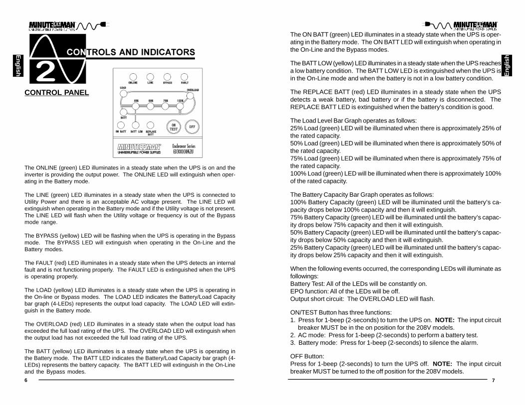
The ONLINE (green) LED illuminates in a steady state when the UPS is on and theinverter is providing the output power. The ONLINE LED will extinguish when oper-ating in the Battery mode.
The LINE (green) LED illuminates in a steady state when the UPS is connected toUtility Power and there is an acceptable AC voltage present. The LINE LED willextinguish when operating in the Battery mode and if the Utility voltage is not present.The LINE LED will flash when the Utility voltage or frequency is out of the Bypassmode range.
The BYPASS (yellow) LED will be flashing when the UPS is operating in the Bypassmode. The BYPASS LED will extinguish when operating in the On-Line and theBattery modes.
The FAULT (red) LED illuminates in a steady state when the UPS detects an internalfault and is not functioning properly. The FAULT LED is extinguished when the UPSis operating properly.
The LOAD (yellow) LED illuminates is a steady state when the UPS is operating inthe On-line or Bypass modes. The LOAD LED indicates the Battery/Load Capacitybar graph (4-LEDs) represents the output load capacity. The LOAD LED will extin-guish in the Battery mode.
The OVERLOAD (red) LED illuminates in a steady state when the output load hasexceeded the full load rating of the UPS. The OVERLOAD LED will extinguish whenthe output load has not exceeded the full load rating of the UPS.
The BATT (yellow) LED illuminates is a steady state when the UPS is operating inthe Battery mode. The BATT LED indicates the Battery/Load Capacity bar graph (4-LEDs) represents the battery capacity. The BATT LED will extinguish in the On-Lineand the Bypass modes.
The ON BATT (green) LED illuminates in a steady state when the UPS is oper-ating in the Battery mode. The ON BATT LED will extinguish when operating inthe On-Line and the Bypass modes.
The BATT LOW (yellow) LED illuminates in a steady state when the UPS reachesa low battery condition. The BATT LOW LED is extinguished when the UPS isin the On-Line mode and when the battery is not in a low battery condition.
The REPLACE BATT (red) LED illuminates in a steady state when the UPSdetects a weak battery, bad battery or if the battery is disconnected. TheREPLACE BATT LED is extinguished when the battery's condition is good.
The Load Level Bar Graph operates as follows:25% Load (green) LED will be illuminated when there is approximately 25% ofthe rated capacity.50% Load (green) LED will be illuminated when there is approximately 50% ofthe rated capacity.75% Load (green) LED will be illuminated when there is approximately 75% ofthe rated capacity.100% Load (green) LED will be illuminated when there is approximately 100%of the rated capacity.
The Battery Capacity Bar Graph operates as follows:100% Battery Capacity (green) LED will be illuminated until the battery’s ca-pacity drops below 100% capacity and then it will extinguish.75% Battery Capacity (green) LED will be illuminated until the battery’s capac-ity drops below 75% capacity and then it will extinguish.50% Battery Capacity (green) LED will be illuminated until the battery’s capac-ity drops below 50% capacity and then it will extinguish.25% Battery Capacity (green) LED will be illuminated until the battery’s capac-ity drops below 25% capacity and then it will extinguish.
When the following events occurred, the corresponding LEDs will illuminate asfollowings:Battery Test: All of the LEDs will be constantly on.EPO function: All of the LEDs will be off.Output short circuit: The OVERLOAD LED will flash.
ON/TEST Button has three functions:1. Press for 1-beep (2-seconds) to turn the UPS on. NOTE: The input circuit breaker MUST be in the on position for the 208V models.2. AC mode: Press for 1-beep (2-seconds) to perform a battery test.3. Battery mode: Press for 1-beep (2-seconds) to silence the alarm.
OFF Button:Press for 1-beep (2-seconds) to turn the UPS off. NOTE: The input circuitbreaker MUST be turned to the off position for the 208V models.
CONTROL PANEL

8 9
English
Eng
lish
INSTALLATION PLACEMENT
This UPS series is intended to be install in a temperature controlled environ-ment that is free of conductive contaminants. Select a location which willprovide good air circulation for the UPS at all times. Avoid locations near heat-ing devices, water or excessive humidity, or where the UPS is exposed to directsunlight. Route power cords so they cannot be walked on or damaged.Operating Temperature (Maximum): 0 to 40 degrees C (+32 to +104 degrees F)Operating Elevation: 0 to 3,000m (0 to +10,000 ft)Operating and Storage Relative Humidity: 95%, non-condensingStorage Temperature: -15 to +45 degrees C (+5 to +113 degrees F)Storage Elevation: 0 to 15,000m (0 to +50,000 ft)
REAR PANEL
INSTALLATIONBe sure to read the installation placement and all the cautions before installingthe UPS. Place the UPS in the final desired location and complete the rest ofthe installation procedure. These UPSs are shipped with the internal batteriesdisconnected. The batteries must be connected before putting these UPSsinto service. Follow the procedure below to connect the batteries and installthe UPS into the rack. USE CAUTION: The UPS is heavy. Use the appropri-ate number of personnel when installing the UPS.
Output Power Receptacles
ED1000RM2U NEMA 5-15P
Model #
ED2000RM2U
ED3000RM2U
ED1500RM2U
Input Power Plug(All power cords are 10ft)
ED1000RMT2U
ED1500RMT2U
NEMA 5-15P
NEMA 5-20P
NEMA L5-30P
NEMA 6-15P
NEMA 6-15P
6-NEMA 5-15R
6-NEMA 5-15R
6-NEMA 5-15/20R1-NEMA L5-20R
4-NEMA 6-15R
6-NEMA 5-15/20R1-NEMA L5-30R
4-NEMA 6-15R
1. The input power cord (120V models). The AC Power Inlet IEC320 (208V models).2. The input circuit breaker will trip in the event the load exceeds the UPS’s power rating.3. The option slot is for option cards.4. The Battery Backup output power receptacles. The output receptacles are electrically wir- ed into two segments to support the "Load Shedding Function". The locking receptacle d- oes not support the Load Shedding Function. NOTE: The locking recptacle is not on all models.5. The External Battery Connector is for connecting External Battery Packs.6. The output circuit breaker will trip in the event the load exceeds the UPS’s power rating.7. The USB Communications Interface Port is for UPS monitoring and control.8. RS232 Communications Interface Port is for UPS monitoring and control.9. The RJ11 REPO (Remote Emergency Power Off) Port is for UPS control.10. The R-J11/R-J45 modular connectors are used for 10/100 Base-T Network/single line Pho- ne/Fax/Modem protection.11. External Ground Stud for connecting an external ground wire.
ED2000RMT2U NEMA L6-20P 4-NEMA 6-15/20R1-NEMA L6-20R
ED3000RMT2U NEMA L6-30P4-NEMA 6-15/20R1-NEMA L6-30R

10 11
Eng
lish
English
RACKMOUNT CONFIGURATIONThe UPS comes with mounting brackets for the standard 19" (46.5cm) rack.The mounting brackets to fit a 23" (59.2cm) standard rack are also available.The screws for mounting the UPS to the rack are not included (screw sizevaries with rack size).1. Locate the mounting bracket screw holes on the side panels of the UPS, at the front of the UPS. NOTE: The mounting brackets can also be mounted in the middle of the UPS.2. Align the mounting bracket with the mounting bracket screw holes.3. Attach the mounting bracket with the retaining screws.4. Mount the UPS into the rack and secure with the retaining screws. WARN- ING: Use two or more people when installing the UPS. Use CAUTION, the UPS is extremely heavy. Do not move the rack after the units have been in- stalled. The rack maybe unstable due to the weight distribution.5. The Rackmount Configuration is complete. See Connecting your Equipm- ent.
CONNECTING THE BATTERIES(QUALIFIED SERVICE PERSONNEL ONLY)Please read all of the WARNINGS and CAUTIONS before attempting to con-nect the batteries.1. Remove the UPS from the shipping box and set on the floor or a bench top.2. Remove the front panel retaining screws.3. Lay the front panel on top of the UPS.4. Verify proper polarity. Connect the battery connectors (red and black) toge- ther.NOTE: Some sparking might occur, this is normal.5. Re-install the front panel onto the UPS.6. Re-install the front panel retaining screws.7. Continue with the rest of the Installation.

12 13
English
Eng
lish
TOWER CONFIGURATIONThe tower configuration allows the user to install the UPS in the up-right position next to thetower computer. The tower brackets are provided with the UPS. WARNING: Use two or morepeople when installing the UPS. Use CAUTION, the UPS is extremely heavy.1. Once the location of the UPS has been determined, place the tower brackets in the desired location.WARNING: The UPS must be installed in the proper up-right position. If the UPS is not installedin the proper up-right position the Batteries will be damaged. Once the UPS is placed in thetower brackets, looking at the front panel the YELLOW Battery disconnected label on the topcover of the UPS MUST be on your left hand side.2. Slide the UPS into the tower brackets. Make sure that the UPS is stable.3. The LED face plate can be rotated to read in the up-right position. Remove the front panel from the UPS. On the backside of the front panel, push the LED face plate outwards the face plate will pop out. Position the LED face plate so that it reads in the up-right position. Re-install the front panel on the UPS.4. The Tower Configuration is complete. See Connecting your Equipment.
DESKTOP CONFIGURATIONThe desktop configuration allows the user to install the monitor, the computer and the UPS inone single stack. WARNING: Use two or more people when installing the UPS. Use CAUTION,the UPS is extremely heavy.1. Once the location of the UPS has been determined, lay the UPS down flat on the desk.2. Stack the computer and then the monitor on top of the UPS. NOTE: Do not stack the UPS on top of the computer. The UPS is heavy and may damage the other equipment.3. The Desktop Configuration is complete. See Connecting your Equipment.
WALLMOUNT CONFIGURATIONThe wallmount configuration allows the user to mount the UPS on the wall. There isa wallmount bracket kit available for the UPS. The kit includes two wall mountingbrackets, ten retaining screws, and the wallmount template. WARNING: Use two ormore people when installing the UPS. Use CAUTION, the UPS is extremely heavy.The UPS's side panels have mounting bracket screw holes for attaching the wallmounting brackets.1. Once the location and position of the UPS has been determined, lay the UPS do- wn flat.WARNING: The UPS must be installed in the proper up-right position. If the UPS isnot installed in the proper up-right position the Batteries will be damaged. Once theUPS is placed on the wall, looking at the front panel the YELLOW Battery discon-nected label on the top cover of the UPS MUST be on your left hand side.2. Align the mounting brackets with the mounting bracket screw holes and attach w- ith the six retaining screws.3. Use the template to mark the screw hole position on the wall. CAUTION, you sh- ould always were protective gear for your hands and eyes when operating power tools.4. Attach the four retaining screws to the wall and make sure that all of the retaining screws are screwed into structural material. Then clean the area of any loose m- aterial. Do not tighten the retaining screws all the way, leave approximately 3/8" of the retaining screws sticking out.5. Position the UPS, so that the mounting bracket keyed holes line up with the four retaining screws. Slide the UPS down until its resting securely on the four retain ing screws.6. Tighten the four retaining screws to secure the UPS to the wall.7. The LED face plate can be rotated to read in the up-right position. Remove the front panel from the UPS. On the backside of the front panel, push the LED face plate outwards the face plate will pop out. Position the LED face plate so that it reads in the up-right position. Re-install the front panel on the UPS.8. The Wallmount Configuration is complete. See Connecting your Equipment.

14 15
English E
nglis
h
CHARGING THE BATTERYThe UPS will charge the internal batteries whenever the UPS is connected toan AC source and there is an acceptable AC voltage present. NOTE: The inputcircuit breaker MUST be in the on position for the 208V models. It is recom-mended that the UPS's batteries be charged for a minimum of 4 hours beforeuse. The UPS may be used immediately, however, the “On-Battery” runtimemay be less than normally expected. NOTE: If the UPS is going to be out ofservice or stored for a prolonged period of time, the batteries must be rechargedfor at least twenty-four hours every ninety days.
COMMUNICATIONS PORT CONNECTION (OPTIONAL)The Power Monitoring Software and interface cables can be used with the UPS.Use only the interface cables that come with these UPSs. Connect the inter-face cable (Serial or USB) to the appropriate communications port on the rearpanel of the UPS. Connect the other end of the cable to the device that will bemonitoring/controlling the UPS. NOTE: Connecting to the CommunicationsPort is optional. The UPS works properly without this connection.
CONNECTING THE UPS TO AN AC SOURCEPlug the UPS into a two pole, three wire, grounded receptacle only. Do not useextension cords, adapter plugs, or surge strips.
NETWORK/PHONE/FAX/MODEM PROTECTION CONNECTION (OPTIONAL)Connect a 10/100 Base-T network, single line phone, Fax or Modem line to theRJ11/45 protection sockets on the rear panel of the UPS. This connection willrequire another length of telephone or network cable. The cable coming fromthe telephone service or networked system is connected to the port marked“IN”. The equipment to be protected is connected to the port marked "OUT".NOTE: Connecting to the Network/Phone/Fax/Modem protection socket con-nection is optional. The UPS works properly without this connection.
CONNECTING YOUR EQUIPMENTPlug the equipment into the output receptacles on the rear panel of the UPS.Do not use extension cords, adapter plugs or surge strips on the output of theUPS. Ensure that you do not exceed the maximum output rating of the UPS(refer to the information label on the UPS or the Electrical Specifications in thismanual).
CAUTION! DO NOT connect a laser printer to the output receptacles on theUPS, unless the UPS is rated 2000VA or greater. A laser printerdraws significantly more power when printing than at idle andmay overload the UPS.
RJ11 REPO (Remote Emergency Power Off) PORT (OPTIONAL)Connect one end of the RJ11 cable to the REPO port and the other end of theRJ11 cable to the EPO switch. In the AC or the Battery mode short pin4 to pin5for approximately 0.5-seconds to shutdown the UPS. The UPS must be turnedoff and then back on again to restart the UPS. NOTE: Connecting to theREPO port is optional. The UPS works properly without this connection.
ON / Test ButtonNOTE: The input circuit breaker MUST be in the on position for the 208Vmodels. Press the ON/Test Button for 1-beep (2-seconds) to turn the UPS onand supply power to the load. In the AC mode press the ON/Test Button for 1-beep (2-seconds) to perform a battery test. In the Battery mode press the ON/Test Button for 1-beep (2-seconds) to silence the audible alarm. The UPS willcontinue to charge the batteries whenever it is plugged into a wall outlet andthere is acceptable AC voltage present.
SYSTEM OVERVIEWThis On-Line UPS protects computers, servers, internetworking, and telecom-munications equipment from blackouts, brownouts, overvoltages, and surges.This On-Line UPS converts the input AC to DC and then back to a True SineWave AC output. The True Sine Wave output is regulated within 2% of thenominal output voltage. The Power Factor Correction (PFC) circuitry correctsthe input power factor to within 97% of unity and blocks the load generatedharmonic distortion from getting back on the input AC line. This On-Line UPSprovides a continuous true sine wave output with zero transfer time and greatregulation to protect your mission critical equipment. The UPS will quietly andconfidently protect your system from power anomalies.
The UPS will charge the batteries with the UPS in the on or off position as longas the UPS is plugged into the AC wall outlet and there is an acceptable ACvoltage present (80/90 - 138VAC/160 - 280VAC). NOTE: The input circuitbreaker MUST be in the on position for the 208V models. When a blackout,brownout, or an overvoltage condition occurs; the UPS will transfer to the bat-tery mode, the On-Battery indicator will illuminate and the audible alarm willsound once every ten-seconds indicating that the commercial power is lost orunacceptable. When the commercial power returns or is at an acceptablelevel, the UPS will automatically transfer back to the normal On-Line mode andstart recharging the batteries. During an extended outage when there is ap-proximately two-minutes of backup time remaining the audible alarm will soundtwice every five-seconds. This Low Battery Warning is letting the user knowthat they should save all open files and turn off their computer. When thebatteries reach the predetermined level the UPS will automatically shutdownprotecting the batteries from over discharging. Once the commercial powerreturns the UPS will automatically restart, providing safe usable power to theconnected equipment and start recharging the batteries.

16 17
English
Eng
lish
ALARMS
ON-BATTERYWhen the UPS is operating on the batteries, the ON BATT LED will illuminateand the audible alarm will sound once every ten-seconds. The alarm will stoponce the UPS returns to the AC normal mode.
LOW BATTERY WARNINGWhen the batteries reach the pre-determined level the BATT LOW LED willilluminate and the audible alarm will sound two beeps every five-seconds. Thiscondition will continue until AC returns or the UPS shuts down from batteryexhaustion.
SELF TESTThe self test feature is useful to verify the correct operation of the UPS and thecondition of the batteries. With the UPS in the AC normal mode, press the ON/Test/Alarm Silencer Button for 1-beep (2-seconds) to perform a battery test.The UPS will perform a ten-second self test. During the self test, the UPS willswitch to battery power and the ON BATT LED will illuminate and the audiblealarm will sound. If the UPS fails a self test, one of the LEDs will remainilluminated indicating the type of problem.
UPS FAULTWhen the UPS detects a hardware fault, the FAULT LED will illuminate and theUPS will sound a constant alarm. The fault condition, in some instances, maybe reset by turning the UPS off and then on again.
LOAD SHEDDING FUNCTIONThe output receptacles are electrically wired into two segments to support the"Load Shedding Function". The user can control the two segments individuallyor both at the same time. The Load Shedding Function is controllable by thePower Monitoring Software or the SNMP card.
OFF ButtonPress the OFF button for 1-beep (2-seconds) to turn the UPS off. NOTE: Theinput circuit breaker MUST be turned to the off position for the 208V models.
OUTPUT VOLTAGE SETTINGSThe inverter output voltage setting may be changed by the user to set thedesired Inverter output voltage. The inverter output voltage setting can be either120VAC (208VAC) default or 110VAC (240VAC). The inverter output voltagecan be changed by using the Output voltage setting software. The softwareprogram is available for download on the web site.
OVERLOADWhen the amount of load attached to the UPS exceeds its power rating, theOVERLOAD LED will illuminate and the UPS will sound a constant alarm. Thisalarm will remain on until the excess load is removed or the UPS’s self protec-tion circuit shuts the UPS down.
COMMUNICATIONS PORTS (RS232 and USB)The RS232 communication port is a standard DB9 female with both RS232 andsimulated contact closure capability. The UPS will poll the port and activatethe port for RS232 or contact closure in accordance with the type of cable itfinds connected to the port. To change the port configuration requires the unitbe turned off and restarted with the desired cable connected. The pinout for theport is depicted per the chart below:Pin 1: Simulated contact closure Low Battery Warning, NOPin 2: /TXDPin 3: /RXD and receive UPS shutdown command (connect to pin9 for 4-sec-onds. The shutdown command is only active in the battery mode)Pin 4: Not UsedPin 5: GroundPin 6: Not UsedPin 7: Not UsedPin 8: Simulated contact closure AC fail, NOPin 9: Atx Signal (high level: 12V ± 2V, low level: -15V ± -2V)
WEAK/BAD BATTERYThe UPS automatically tests the battery’s condition and will illuminate theREPLACE BATT LED and sound the alarm. This alarm will be repeated untilthe batteries pass a self test. If the battery is weak or bad, the REPLACEBATT LED will illuminate and the alarm will beep three times every five-minutesuntil the battery is replaced. It is recommended that the UPS be allowed tocharge overnight before performing a battery test to confirm a Weak/Bad Bat-tery condition.NOTE: If the UPS has a REPLACE BATT Alarm after reconnecting or replacingthe batteries, the user must initiate a self test to clear the REPLACE BATTAlarm. To initiate a self test see section 4 "SELF TEST".
POWER MONITORING SOFTWAREThe UPS comes with a Power Monitoring Software CD. See the software CDfor the installation of the Power Monitoring Software.
USB PORTThe USB protocol is HID. The HID USB driver is standard in the Windows OS.Simply plug the USB cable into the UPS and the computer then follow theprompts on the screen.
OPTION SLOTThe option slot on the rear panel of the UPS is for option cards. Contact yourlocal dealer for the available option cards.
RJ11 REPO (Remote Emergency Power Off) PORTIn the AC or the Battery mode short pin4 to pin5 for approximately 0.5-secondsto shutdown the UPS. The UPS must be turned off and then back on again torestart the UPS.

18 19
English
Eng
lish
Possible CauseSymptom What To Do
Press and release the On/Off/Test button to start UPS
On/Off/Test button notpushed
UPS will not turn on
Reset circuit breaker bypressing the plunger back in.If the AC circuit breaker tripsafter UPS starts up, reducethe load on the UPS
UPS operates inbattery mode only,even though there isnormal AC present
Input AC circuit breaker istripped
UPS has detected an inter-nal fault
Call for serviceFault LED is illumi-natedThe On-Line LEDis illuminated, butthere is no output
Disconnect the computercable from the UPS and pressthe On button. If UPS worksnormally, the software hascontrol of the UPS
The UPS is being con-trolled via its communica-tions port
The batteries may be weakor at the end of usefulservice life
Charge the batteries for 8hours and retest. -If theruntime is still less than ex-pected, the batteries mayneed to be replaced, eventhough the Weak/Bad BatteryLED is not illuminated
UPS does not pro-vide the expectedruntime
Weak/Bad BatteryLED is illuminated
Overload LED isilluminated and aconstant alarm
The On-Line LED isilluminated and LoadSegment 1 has anoutput, but there isno output from LoadSegment 2
Loose connections at thebatteries, Weak batteries,Bad batteries
The load has exceeded theUPS's capacity
The output breaker for LoadSegment 2 is tripped,Load Segment 2 wasturned off by the softwareor the SNMP card
Check battery connections,charge the batteries for 8-hours and then retest, replacethe batteries
Check the specifications (seesection 8). Remove part ofthe loadReset the output breaker forLoad Segment 2, turn on LoadSegment 2 by the software orthe SNMP card
REPLACING THE BATTERY
WARNING! This Uninterruptible Power Supply contains potentially hazardousvoltages. Do not attempt to disassemble the UPS beyond thebattery replacement procedure. This UPS contains nouser serviceable parts. Repairs and Battery replacement mustbe performed by QUALIFIED SERVICE PERSONNEL ONLY.
Do not open or mutilate batteries. Released electrolyte is harmfulto the skin and eyes and may be toxic.
CAUTION:
(QUALIFIED SERVICE PERSONNEL ONLY)
CAUTION: Do not dispose of batteries in a fire. The batteries may explode.The batteries in this UPS are recyclable. Dispose of the batteriesproperly. The batteries contain lead and pose a hazard to theenvironment and human health if not disposed of properly. Referto local codes for proper disposal requirements or return thebattery to the supplier.Although battery system voltages are only 24VDC, 48VDC and72VDC the battery system can still present a risk of electricalshock. These batteries produce sufficient current to burn wire ortools very rapidly, producing molten metal. Observe these pre-cautions when replacing the batteries:1. Remove watches, rings, or other metal objects.2. Use hand tools with insulated handles.3. Wear protective eye gear (goggles), rubber gloves and boots.4. Do not lay tools or other metal parts on top of batteries.5. Disconnect the charging source prior to connecting or disco- nnecting the battery terminals.6. Determine if the battery is inadvertently grounded. If the batte- ry is, remove the source of the grounding. Contact with any p- art of a grounded battery can result in an electrical shock. The likelihood of such shock will be reduced, if such grounds are removed during installation and maintenance.
CAUTION:
The UPS has an easy to replace hot-swappable batteries. Please read all ofthe WARNINGS and CAUTIONS before attempting to service the batteries.NOTE: If there is a power interruption while replacing the hot-swappable
batteries, with the UPS on, the load will not be backed up.

20 21
English E
nglis
h
BATTERY REPLACEMENT PROCEDUREPLEASE READ THE CAUTIONS AND WARNINGS BEFORE ATTEMPTINGTO REPLACE THE BATTERIESHot-swappable batteries mean that the batteries can be replaced withoutpowering down the whole UPS system.NOTE: If there is a power interruption while replacing the hot-swappable batte-
ries, with the UPS on, the load will not be backed up. To hot-swap thebatteries start with step number 6.
1. Turn off the equipment that is plugged into the output receptacles of the UPS.2. Press the OFF button to turn the UPS off. NOTE: The input circuit breaker MUST be turned to the off position for the 208V models.3. Unplug the UPS's AC power cord from the AC wall outlet.4. Unplug the equipment from the output receptacles of the UPS.5. Unplug the computer interface cable from the rear panel of the UPS.6. Remove the front panel retaining screws. (FIG. 2)7. Lay the front panel on top of the UPS.
ED1000RM2UED1000RMT2U
ED1500RM2UED1500RMT2U
BatteryQty/Rating
2-12V8.5Ah 4-12V7.2Ah
ED3000RM2UED3000RMT2U
6-12V8.5Ah
Model #
Replace batteries with the same number and type as originallyinstalled in the UPS. These batteries have pressure operated vents.These UPSs contain sealed non-spillable maintenance-free leadacid batteries.
CAUTION:
PanasonicPart #
YuasaPart #
REW45-12
CSBPart #
NP-7.2-12 REW45-12
LC-R129 LC-R127.2 LC-R129
HR 1234W F2 GP 1272 F2 HR 1234W F2
FIG. 1 FIG. 2
ED2000RM2UED2000RMT2U
4 -12V8.5Ah
REW45-12
LC-R129
HR 1234W F2
8. Remove the two retaining screws for the battery retaining bracket. (FIG. 3)9. Remove the battery retaining bracket. (FIG. 3)10. Disconnect the Battery connectors (red and black). (FIG. 4)11. Grasp the battery pull tab and gently pull the battery module out of the UPS and set on the floor. (FIG. 4)NOTE: Use Caution, the battery module is heavy.12. Disconnect the battery positive (red) wire.13. Disconnect the battery negative (black) wire.14. Remove the battery jumper wires.15. Remove the old batteries from the battery module.16. Install the new batteries into the battery module in the same position as the original batteries.17. Verify proper polarity. Re-install the battery jumper wires on the new batt- eries.18. Verify proper polarity. Reconnect the battery negative (black) wire.19. Verify proper polarity. Reconnect the battery positive (red) wire.20. Slide the battery module into the UPS.21. Verify proper polarity. Reconnect the battery connectors (red and black).NOTE: Some sparking might occur, this is normal.22. Re-install the battery retaining bracket.23. Re-install the two retaining screws for the battery retaining bracket.24. Re-install the front panel on the UPS.25. Re-install the front panel retaining screws.26. Properly dispose of the old batteries at an appropriate recycling facility or return them to the supplier in the packing material for the new batteries.27. The UPS is now ready for the normal operation.NOTE: If the UPS has a Weak/Bad Battery Alarm after replacing the batteries,the user must initiate a self test to clear the Weak/Bad Battery Alarm. Toinitiate a self test see section 4 "SELF TEST".
FIG. 3 FIG. 4

22 23
English E
nglis
h
IF THE UPS REQUIRES SERVICE
1. Use the TROUBLESHOOTING section to eliminate obvious causes.2. Verify there are no circuit breakers tripped. A tripped circuit breaker is the most common problem.3. Call your dealer for assistance. If you cannot reach your dealer, or if they cannot resolve the problem call or fax MINUTEMAN Technical Support at the following numbers; Voice phone (972) 446-7363, FAX line (972) 446- 9011 or visit our Web site at www.minutemanups.com the "Discussion Board". Please have the following information available BEFORE calling the Technical Support Department.
A. Your name and address. B. Where and when the unit was purchased. C. All of the model information about your UPS. D. Any information on the failure, including LEDs that may be illuminated. E. A description of the protected equipment, including model numbers if pos-
sible. F. A technician will ask you for the above information and, if possible, help
solve your problem over the phone. In the event that the unit requires factory service, the technician will issue you a Return Material Authoriza-
tion Number (RMA #). G. If the UPS is under warranty, the repairs will be done at no charge. If not,
there will be a charge for repair.4. Pack the UPS in its original packaging. If the original packaging is no longer
available, ask the Technical Support Technician about obtaining a new set. It is important to pack the UPS properly in order to avoid damage in transit. Never use Styrofoam beads for a packing material. A. Include a letter with your name, address, day time phone number, RMA
number, a copy of your original sales receipt, and a brief description of the problem.
5. Mark the RMA # on the outside of all packages. The factory cannot accept any package without the RMA # marked on the outside.
6. Return the UPS by insured, prepaid carrier to:
Para Systems Inc.MINUTEMAN UPS1455 LeMay Drive
Carrollton, TX 75007ATTN: RMA # _______
Default: 120VAC (208VAC), User selectable: 110VAC (240VAC)
1500VA/1200W1000VA/800W
Protection
Waveform Type
Over-Current, Short-Circuit Protected and Latching Shutdown
True Sine Wave
Frequency 50/60Hz, +/-0.1Hz (unless synchronized to utility)
Nominal Voltage
Maximum Power Capacity
0 ms
>87% (Full Load)
Resettable Circuit Breaker
50 or 60 Hz, +/-6Hz, autosensing
0 - 150VAC (0 - 300VAC)
90 - 138VAC (160 - 280VAC)
120VAC: 117.6 - 122.4VAC (208VAC: 204 - 212VAC)
Transfer Time
Efficiency (Line Mode)
Input Protection
Frequency Limits
Voltage Range
Acceptable Input voltage
ED1500RM2UED1500RMT2U
ED1000RM2UED1000RMT2U
Model Number
SYSTEM SPECIFICATIONS
Voltage Range
Topology Double Conversion On-Line, True Sine Wave
OUTPUT ON-LINE OPERATION
INPUTNumber of Phase Single (1∅ 2W +G)
Nominal Voltage 120VAC (208VAC)
Low Voltage Transfer Point 80/90V (160V) resets to Utility Power at 86/96V (170V) or higher
High Voltage Transfer Point 138V (280V) resets to Utility Power at 132V (270V) or lower
Voltage Regulation Nominal +/-2%
Frequency Range 60Hz: 54 - 66Hz or 50Hz: 44 - 56Hz
OUTPUT BATTERY OPERATION
Voltage Regulation Nominal +/-2% (until Low Battery Warning)
Voltage T.H.D. <3% (Linear Load)
+/-5% @ 100% Load change in 30 msDynamic Response
Slew Rate <1Hz / second
Overload Capacity>115% - <125% for 60-seconds>125% - <150% for 30-seconds>150% for 1-second
ED2000RM2UED2000RMT2U
ED3000RM2UED3000RMT2U
2000VA/1600W 3000VA/2100W
80 - 138VAC(160 - 280VAC)
Power Factor Correction >97% at Full Load
Crest Factor 3 : 1
24 25
Eng
lish
English
BATTERY SYSTEM
Typical Recharge Time
Typical Battery Life
Battery: Quantity/Rating
3-5 years, depending on discharge cycles and ambient temp
4-12V7.2Ah
8-hours from total discharge
4-12V8.5Ah
Battery Type Sealed, Non-Spillable, Maintenance Free, Value Regulated Lead Acid
System Voltage 48VDC 48VDC
Runtime: Full Load (minutes)
Runtime: Half Load (minutes) 1313
44
SURGE PROTECTION AND FILTERING
Audible Noise at 1 m (3 ft.)
10/100 Base-T surge protec-tion let-through (as a percent-age of an applied +/-6 kV 1.2/50 us, 500 a 8/20 uS test)
Telephone line surge protec-tion let-through (as a percent-age of an applied +/-6 kV 1.2/50 us, 500a 8/20 uS test)
Noise Filter
Surge voltage let-through (asa percentage of an appliedANSI C62.41 Cat. A +/-6 kV)
Surge Response Time
Surge Current Capability
Surge Energy Rating 800 J (600 J)
0 ns (instantaneous) normal mode; <5 ns common mode
<5%
normal and common mode EMI/RFI suppression
<45 dBA
<1%
<5%
6500 Amps total
ENVIRONMENTALOperating Temperature (max)
Operating/Storage Humidity
Operating Elevation
0 to 40°C (+32 to +104°F)
95% Non-Condensing
0 to 3,000m (0 to +10,000 ft)
PHYSICAL
Weight - Net
Size - NetD X W X H
Size - ShippingD X W X H
Weight - Shipping
43.1 lbs19.6 Kgs
67.7 lbs30.7 Kgs
13.1 x 17.3 x 3.5"335 x 440 x 89 mm
23.6 x 20.0 x 9.0"600 x 508 x 230 mm
52.0 lbs23.3 Kgs
80.0 lbs35.9 Kgs
REGULATORY COMPLIANCE
Safety and Approvals
EMC Verification
UL1778, cUL (CSA 22.2 no. 107.1)
FCC, CE certified
Storage Elevation 0 to 15,000m (0 to +50,000 ft)
Storage Temperature -15 to +45°C (+5 to +113°F)
24VDC 72VDC
2-12V8.5Ah 6-12V8.5Ah
15
5
13
4
<60 dBA
24.0 x 17.3 x 3.5"610 x 440 x 89 mm
39.4 x 23.6 x 9.0"1000 x 600 x 230 mm
46.2 lbs21.0 Kgs
55.0 lbs24.7 Kgs
40.0 lbs17.9 Kgs
29.0 lbs13.2 Kgs
17.0 x 17.3 x 3.5"432 x 440 x 89 mm
23.6 x 20.0 x 9.0"600 x 508 x 230 mm
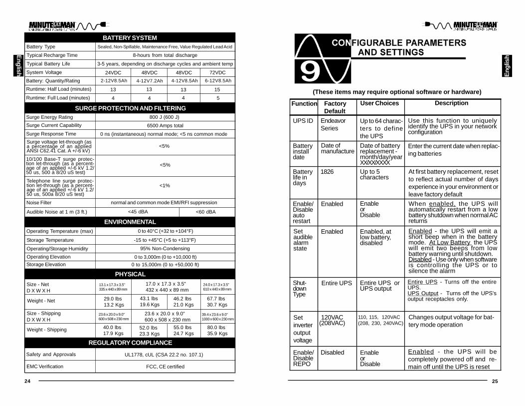
(These items may require optional software or hardware)
Function FactoryDefault
DescriptionUser Choices
Setinverteroutputvoltage
Shut-downType
Setaudiblealarmstate
Enable/Disableautorestart
Batterylife indays
Batteryinstalldate
UPS ID EndeavorSeries
Date ofmanufacture
1826
Enabled
Enabled
Entire UPS
120VAC(208VAC)
Up to 64 charac-ters to definethe UPS
Date of batteryreplacement -month/day/yearXX/XX/XXXXUp to 5characters
EnableorDisable
Enabled, atlow battery,disabled
Entire UPS orUPS output
110, 115, 120VAC(208, 230, 240VAC)
At first battery replacement, resetto reflect actual number of daysexperience in your environment orleave factory default
Enter the current date when replac-ing batteries
Use this function to uniquelyidentify the UPS in your networkconfiguration
Changes output voltage for bat-tery mode operation
Enabled - the UPS will emit ashort beep when in the batterymode. At Low Battery the UPSwill emit two beeps from lowbattery warning until shutdown.Disabled - Use only when softwareis controlling the UPS or tosilence the alarm
When enabled, the UPS willautomatically restart from a lowbattery shutdown when normal ACreturns
Enable/DisableREPO
Disabled EnableorDisable
Enabled - the UPS will becompletely powered off and re-main off until the UPS is reset
Entire UPS - Turns off the entireUPS.UPS Output - Turns off the UPS'soutput receptacles only.

26 27
English
Eng
lish
Para Systems Inc. (Para Systems) warrants this equipment, when properlyapplied and operated within specified conditions, against faulty materials orworkmanship for a period of three years from the date of purchase. For equip-ment sites within the United States and Canada, this warranty covers repair orreplacement of defective equipment at the discretion of Para Systems. Repairwill be from the nearest authorized service center. Replacement parts andwarranty labor will be borne by Para Systems. For equipment located outsideof the United States and Canada, Para Systems only covers faulty parts. ParaSystems products repaired or replaced pursuant to this warranty shall be war-ranted for the unexpired portion of the warranty applying to the original product.This warranty applies only to the original purchaser who must have properlyregistered the product within 10 days of purchase.
The warranty shall be void if (a) the equipment is damaged by the customer, isimproperly used, is subjected to an adverse operating environment, or is oper-ated outside the limits of its electrical specifications; (b) the equipment is re-paired or modified by anyone other than Para Systems or Para Systems ap-proved personnel; or (c) has been used in a manner contrary to the product’sUser's Manual or other written instructions.
Any technical advice furnished before or after delivery in regard to use or appli-cation of Para Systems’s equipment is furnished without charge and on thebasis that it represents Para Systems’s best judgment under the circumstances,but it is used at the recipient’s sole risk.
EXCEPT AS PROVIDED HEREIN, PARA SYSTEMS MAKES NO WARRAN-TIES, EXPRESSED OR IMPLIED, INCLUDING WARRANTIES OF MERCHANT-ABILITY AND FITNESS FOR A PARTICULAR PURPOSE. Some states do notpermit limitation of implied warranties; therefore, the aforesaid limitation(s) maynot apply to the purchaser.
EXCEPT AS PROVIDED ABOVE, IN NO EVENT WILL PARA SYSTEMS BELIABLE FOR DIRECT, INDIRECT, SPECIAL, INCIDENTAL, OR CONSEQUEN-TIAL DAMAGES ARISING OUT OF THE USE OF THIS PRODUCT, EVEN IFADVISED OF THE POSSIBILITY OF SUCH DAMAGE. Specifically, Para Sys-tems is not liable for any costs, such as lost profits or revenue, loss of equip-ment, loss of use of equipment, loss of software, loss of data, cost of substi-tutes, claims by third parties, or otherwise. The sole and exclusive remedy forbreach of any warranty, expressed or implied, concerning Para Systems’s prod-ucts and the only obligation of Para Systems hereunder, shall be the repair orreplacement of defective equipment, components, or parts; or, at Para Systems’soption, refund of the purchase price or substitution with an equivalent replace-ment product. This warranty gives you specific legal rights and you may alsohave other rights which vary from state to state.
Longer term warranties are available at an additional cost. Contact Para Sys-tems (1-972-446-7363) for details.
LIMITED PRODUCT WARRANTY(Continued)

28 29
English E
nglis
h
A1. DECLARATION OF CONFORMITY
Application of Council Directive(s): 89/336/EEC, 73/23/EEC
Standard(s) to which Conformity is declared:
Manufacturer’s Name: Para Systems, Inc. (MINUTEMAN UPS)
Manufacturer’s Address: 1455 LeMay DriveCarrollton, Texas 75007 USA
Type of Equipment: Uninterruptible Power Supplies (UPS)Model No: ED1000RM2U (Y), ED1500RM2U (Y),
ED2000RM2U (Y), ED3000RM2U (Y)
I, hereby declare that the equipment specified above conforms to the aboveDirective(s).
Place: Carrollton, Texas, USA Date: June 30, 2006
Robert Calhoun (Name)
Manager Engineering (Position)
Year of Manufacture: Beginning June 30, 2006
EN55022, EN55024EN61000-6-1, EN61000-6-3EN61000-4-5
Notes:

30
English
Notes: