enclosure 4 revision to calculation wcg-acq-0275 … · nozzle, on the qualification of the 6'...
TRANSCRIPT

0 0ENCLOSURE 4
REVISION TO CALCULATION WCG-ACQ-0275
RWST 6 AND 8 INCH NOZZLE QUALIFICATION
9206070155 920727PDR ADOCK 05000390A PDR

0RIGI NALO
Bechtel JobBRANCH/PROJECT IDEP
yJC5- AcQ-APPLICABLE DESIGN DC
A1.4.
CUMENT(S)
SAR SECTION(S) UNID SYSTEM(S)3N/A
Revision 0ECN No. lOr indicate Not Applicablelor DCN No.. t,/APrepared 4 k196
Checked,cý ..... .. l
A 19
List all Pages added sE." Rrv- by this revision. "
- List all pages deleted _- , by this revision.
-. List all p chang _ _ 6" -V.by this revision. Z
These calculations contain Yes Yes Qunverified assumption(s) ]No IE NoX
Abstract A Fi tj -Tc
105-03B0OU02 8281 91 0308 152ulh- U(IU 4UCO
RI R ZR Safety-related Yes No
Statement of ProblemLI-UALi-•f• • UO .- /..-.e•..
-.TJA-)CT-UP-6: IX)C TD .o~'L
C->ZT5 ;.; jA L. L- 4A- ; O 4•+J -- '
TA-7,Uk-'.
P~t~-OpeFDab7-0 &L LD I :A-T~~~~~he~A AUP~~T CkTcz~.c-~ Ev2- ..510 4-ac-E -
MOJ 0L- LOeA LkS O-j -ME 7A.- AJAu~y~'L5
OS C-o- FLoIA 'ý6 0 Co-j,qJ7M-JM&~iJ7 -5-P02A-q. 7E!ST I-W- . -, r LEG!BILITY EVALUATED and
o .--m f- ACCEPTED for issue.
0O-Tc~ A -O 'P /(1____
A 24' intr date
(AMSyS OUTPUT)Mfcrolin: ,land store c,•.CieiOnsl ir RIMS Service Center
Microfilm and oestroy. -M'Crof0 n On" MtU-i c3CIeI-OMh to C oM r2 Lfilm Address : -M -1,9ry )• I
c RIMS, S 26-
!
E Lem-0E,-T- A 0A L Y 5 1 S _.
.... DNE CALCULATIONS " flR "A•.
S" PLANT/UNITMTION KEY NO (Consult RIMS DESCRIPTORS LIST) I20652 EQ(UpL M T &-L)ALIFPcA7toj ,joV:7;Le SWEL-L 573P76SC-4TIFIERS. Each time thee calculations We issed* PtWerprt Must ensure that the original ERO) RIMS 'cmegonnutlber is filled in. a"
Rev (for RIMS* use) RIMS accession number027.- RO 9I0ZIICOc>4? Rf-I 1O11C04 F R qn nQý17 1 R4-
------ REVISION LOG
Title: ~-~C -.-. c cA
Revision RDateNo. DESCRIPTION OF REVISION Approved
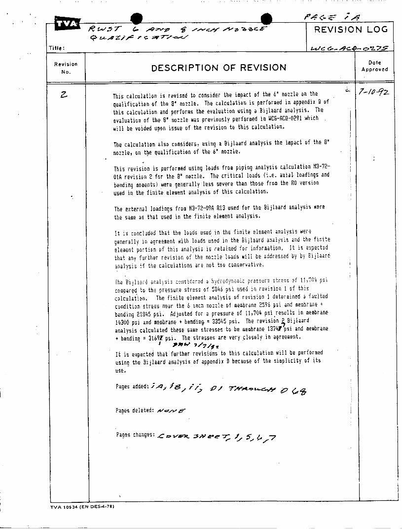
This calculation is revised to consider the imoact of the 6- nozzle on thhe
qualification of the So nozzle. The calculation is performed in appendix D of
this calculation and performs the evaluation using a Bijlaard analysis. The
evaluation of the 8' nozzle was previously performed in KCG-ACQ-0291 which
will be voided upon issue of the revision to this calculation.
The calculation also considers, using a Bijlaard analysis the impact of the 8'
nozzle, on the qualification of the 6' nozzle.
This revision is performed using loads from piping analysis calculation N3-72-
0IA revision 2 for the 8' nozzle. The critical loads (i.e. axial loadings and
bending moments) were generally less severe than those from the RO version
used in the finite element analysis of this calculation.
The external loadings from N3-72-09A R13 used for the Bijlsard analysis were
the same as that used in the finite element analysis.
It is •on-cluded that the loads used in the finite Element a... ysi- were
genreraiy in agreement with loads used in the Bijlaard analysis and the fir.te
element portion of this analysis is retained for infoation. " I i s expectEd
that any further revi sio of the noz:iE loa•s will be addressed by by Biijiaar
anralysis f the calculatinns are rot too c.nservative.
comoared to the pressure Stress of 246 psi used :n revision 1 of thi-
ceiculatýon. The finite element analysis of revision 1 duterrmui'ed a faulted
condition stress near the 6 inch nozzle of membrane 2596 psi and membrane +
bending 21•2• psi. Adjusted for a pressure of 11,704 psi .results in membrane
14300 psi and membrane + bending, = 33545 Usi. The revision 4 Bijlaard
analysis calculated these same stresses to be membrane 13747 psi and membrane
+ bending = 3169tpsi. The stresses are very closely in agreement.
1t is expected that further revisions to this calculation will be performed
using the Bijlaard analysis of appendix D because of the simplicity of its
use,
Pages added: i / //; •, ,;• ._,,
PaNes deleted. ,',--
Pages changes:
TVA 10534 (EN DES-4-7T)
* SWBNP UNIT 1 WCG-ACQ-0275 PAGE /
PREPARED .DATE-/72"A-z, CHECKED- f DATE 7-2 -.
APPENDIX D: BIJLAARD ANALYSIS OF 8" (AND 6") NOZZLE
THIS SHEE.T ADDED BY RE-V
THISOHEET ADDED BY REVWBNP UNIT 1 WCG-ACQ-0275 -PAGE P-ePREPARED Pý W DATETEe',<,I: CHECKED QF DATE 7-g-1
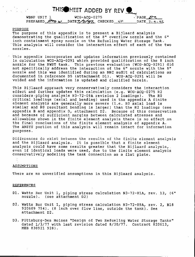
PURPOSEThe purpose of this appendix is to present a Bijlaard analysisdemonstrating the qualification of the 8" overflow nozzle and the 6"inch containment spray nozzle on the Refueling Water Storage Tank.This analysis will consider the interaction effect of each of the twonozzles.
This appendix incorporates and updates information previously containedin calculation WCG-ACQ-0291 which provided qualification of the 8 inchnozzle for the RWST tank. This previous evaluation (WCG-ACQ-0291) didnot specifically address the interaction of the 6" nozzle with the 8"nozzle and this was identified during an NRC audit of calculations asdocumented in reference D5 (attachment Dl). WCG-ACQ-0291 will bevoided and the information is updated and clarified herein.
This Bijlaard approach very conservatively considers the interactioneffect and further updates this calculation (e.g. WCG-ACQ-0275 R2considers.piping analysis N3-72-09A revision 2 loadings). The ROcritical loadings (axial and bending) used in the appendix A finiteelement analysis are generally more severe (i.e. RO axial load issimilar and RO resultant bending is larger) than the R2 loadings (seeappendix B and appendix D, attachment D2. Because of this conservatismand because of sufficient margins between calculated stresses andallowables shown in the finite element analysis there is no effect onthe final conclusions of the finite element analysis of appendix A.The ANSYS portion of this analysis will remain intact for informationpurposes.
Differences do exist between the results of the finite element analysisand the Bijlaard analysis. It is possible that a finite elementanalysis could have some results greater that the Bijlaard analysis,even if identical loads were used, due to the finite element analysisconservatively modeling the tank connection as a flat plate.
ASSUMPTIONS
There are nyo unverified assumptions in this Bijlaard analysis.
REFERENCES
D1. Watts Bar Unit 1, piping stress calculation N3-72-01A, rev. 13, (6"nozzle). (see attachment D2)
D2. Watts Bar Unit 1, piping stress calculation N3-72-09A, rev. 2, B18920609 754). (8 inch over flow line, outside the tank). Seeattachment D2.
D3. Pittsburg-Des Moines "Design of Two Refueling Water Storage Tanks"dated 1/3/77 with last revision dated 8/30/77. Contract 820613,MEB 830921 928).

.'TH!S S'FrT D 4Y REV _ NEWBNP UNIT 1 WCG-ACQ-0275 PAGE 4PREPARED - DATE 7,'V -z- CHECKED tM DATE-_7-1-7
D4. Pitsburg-Des Moines stress report providing additional informationfor the reference D3 "Design of Two Refueling Water Storage Tanks"received on 8/14/80. Contract 820613. B07 890915 067. Portions ofthis report providing loadings are contained in attachment D2.
D5 Letter from NRC's P.S. Tam to TVA's M. Medford dated May 26 1992(perinent portions are contained in attachment D1 of thisappendix).
D6. Welding Research Council Bulletin 107 "Local Stresses in Sphericaland Cylindrical Shells due to External Loadings" dated April 1972(third revised printing of August 1965 WRC 107).
D7. WBN Report CEB-81-41, "Watts Bar Nuclear Plant, Seismic Analysis ofRefueling Water Storage Tank" B26 910424 077.
D8. WB-DC-40-31.6, R4 "Seismically Qualifying Tanks and Reservoirs andTheir Supports" (T29 920521 939).
D9. PDM drawings 50039 D2, D9, E9, contract 820613. Pertinent portionsof these drawings are reproduced in attachment D3 of this appendix.
CALCULATIONS/EVALUATIONS
The nozzle loadings will be evaluated to the stress levels identifiedin Design Criteria WB-DC-40-31.6 (ref. D3).
The allowable stresses are:Design! Upset Emergency FaultedNormal
Pm l.OSh l.lSh 1.5Sh 2.OSh(Pm or P1) + Pb 1.5Sh 1.65Sh 1.8Sh 2.4Sh
When evaluating the results of the Bijlaard analysisPm is taken as Pm + Pl(membrane);and (Pm or P1) + Pb is conservatively taken as Pm + Pl(membrane +bending).
Per FSAR section 9.2.7 the design and operating pressures areatmospheric with a design temperature of 200F. The maximum operatingtemperature of 145 0 F is conservative per discussions between thesystems engineer (Steve Robertson) and the preparer of this calculation(D. M. Wilson) on 6/15/92. The allowable stress "Sh" is taken as 18350psi. Therefore:Normal ConditionPm + Pl(membrane) < 1.OSh = 18350 psiPm + Pl(membrane + bending) < 1.5Sh 27525 psiUpset ConditionPm + Pl(membrane) < l.lSh = 20185 psiPm + Pl(membrane + bending) + Pb < 1.65Sh = 30278 psiFaulted ConditionPm + Pl(membrane) < 2.OSh = 36700 psiPm + Pl(membrane + bending) < 2.4Sh = 44040 psi

THIS SHEET ADDSE BY REV -
WBNP UNIT 1 WCG-ACQ-0275 PAGE 2 .PREPARED _ DATE_7 7CHECKED DF DATE 7-1-11"
The pressure load is considered as a primary general membrane stress Pmand the gross bending stress due to seismic loading will also beconsidered as a primary general membrane stress.
Allowable nozzle loads were obtained for the original PDM analyses(ref. D3 and D4 ). These approved values were investigated by PDMusing a Bijlaard analysis and approved in the reference D3 calculation.Reference D4 provided an evaluation of the piping internal to the tankand provided actual loads for the piping inside. The PDM allowableswere determined to be good for the external piping and are listed belowfor information.
ALLOWABLE LOADS FROM EXTERNAL PIPING(Ref. D3, page 6.2)
AXIAL SHEAR BENDING TORSIONPx Py, Pz Mby, Mbz Mtx
axial long. circ. circ long torsion(lb) (lb) (in-lb) (in-lb)
6" nozzleNORMAL,allow 1480 1050 1050 11270 11270 31875UPSET,allow 2105 1395 1395 15025 15025 42500EMERGENCY,allow 2737 1745 1745 18700 18700 5312FAULTED,allow 2737 17415 1745 18700 18700 53125
8" NOZZLE,NORMAL,allow 1575 1575 1575 22285 22285 63040UPSET,allow 2100 2100 2100 29710 29710 84050EMERGENCYallow 2625 2625 2625 37140 37140 105065FAULTED,allow 2625 2625 2625 37140 37140 105065
Actual external loadings listed below were obtained from pipinganalysis N3-72-01A R13 (ref. Dl) for the 6" nozzle and N3-72-09A R2(ref. D2) for the 8" nozzle.
The actual loadings from N3-72-09A R2 (8" overflow nozzle) considersthe piping from outside the tank. For this loading revision thesubmitted values are-below the allowable values for all conditions.Further evaluation of these loadings will, however, be performed inthis calculation. Loadings were determined at the shell nozzlejuncture.
The actual loadings from N3-72-01A R13 (6" containment spray nozzle)considered the piping from outside the tank. From a review of theisometric and discussions with a piping analyst (J. Valazquez), it wasconfirmed that the loadings were applied at the safe end of the nozzlewith a 6" length. The actual bending moments are conservativelyconverted into bending moments at the nozzle/pad junction bymultiplying the shear force at the node point by the distance from thenode point to the nozzle/pad interface (6").
Adjusted Mby = Mby + (6)PzAdjusted Mbz = Mbz + (6)Py

T ADDED BY REV
WBNP UNIT 1 WCG-ACQ-0275 PAGE4..-PREPARED 7 - DATE 7T/7 z -CHECKED f DATE 7-t. q
In the table below, the adjusted moments are shown and the moments atthe safe end are shown in parentheses for the 6 inch nozzle. Theindividual load components which exceed the vendor allowables areunderlined for clarity.
ACTUAL EXTERNAL(see pages D54 and D55 of
AXIAL SHEARPx Py,
axial long. c
6" nozzleNORMAL,actualNORMAL,allow
UPSET,actualUPSET,allow
FAULTED,actualFAULTED,allow
8" NOZZLE,NORMAL,actualNORMAL,allowUPSET,actualUPSET,allowFAULTED,actualFAULTED,allow
(Ib)
11161480
(ib)
7841050
2013 16962105 1395
3243 26682737 1745
2531575530
2100767
2625
122015751594210019142625
NOZZLE LOADSthis calculation)
BENDINGPz Mby, Mbzirc. circ long
(in-lb)(24276) (23148)
222 25608 278521050 11270 11270
(32700) (46824)1015 3 570001395 15025 15025
(44124) (78564)1820 55044 945721745 18700 18700
415752742100499
2625
37222856625
297101204937140
169032228524816297103155637140
The actual external loads from the 6" nozzle exceeded vendorallowables for several of the loading conditions. The actual loadsfrom the 8" nozzle were within allowable limits for the revision 2loads.
The internal loads will be conservatively combined with the externalloads disregarding signs and the loads for performing the Bijlaardanalysis are developed.
The internal loadings are obtained from the PDM analysis (ref. D4) andare tabulated below. Note that for the 8" internal nozzles verticaland axial loads are essentially carried by the lower support and thetransverse loads are carried by the nozzle.
TORSIONMtx
torsion(in-lb)
4018831875
7362042500
10825253125
511630403940
840506625
105065
WBN7 ADDED BY REVWBNP UNIT 1 WCG-ACQ-0275 PAGE r.PREPARED g-gyf •_" DATE Zoý.tZ_. CHECKED pj p DATE -7 -1 - .
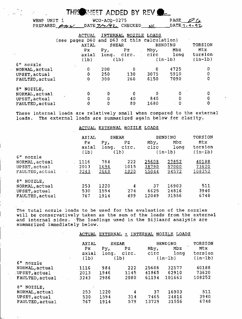
ACTUAL INTERNAL NOZZLE LOADS(see pages D60 and D63 of this calculation)
AXIAL SHEAR BENDINGPx Py, Pz Mby, Mbz
axial long. circ. circ long
6" nozzleNORMAL,actualUPSET,actualFAULTED,actual
8" NOZZLE,NORMAL,actualUPSET,actualFAULTED,actual
(ib) (Ib)
200250300
0130260
(in-lb)
030756150
TORSIONMtx
torsion(in-lb)
472559107090
8401680
These internal loads are relatively small when compared to the externalloads. The external loads are summarized again below for clarity.
ACTUAL EXTERNAL NOZZLE LOADS
6" nozzleNORMAL,actualUPSET,actualFAULTED,actual
AXIALPx
axial(lb)
111620133243
SHEARPy, Pzlong. circ.
(lb)
78416962668
22210151820
BENDING TORSIONMby, Mbz MtXcirc long torsion
(in-lb) (in-lb)
256083879055044
2785257000945~7~2
4018873620
108252
8" NOZZLE,NORMAL,actual 253 1220 4 37 16903 511UPSET,actual 530 1594 274 6625 24816 3940FAULTED,actual 767 1914 499 12049 31556 6748
The total nozzle loads to be used for the evaluation of the nozzleswill be conservatively taken as the sum of the loads from the externaland internal sides. The loadings used in the Bijlaard analysis aresummarized immediately below.
ACTUAL EXTERNAL + INTERNAL NOZZLE LOADS
6" nozzleNORMAL,actual.UPSET,actualFAULTED,actual
8" NOZZLE,NORMAL,actualUPSET,actualFAULTED,actual
AXIAL SHEARPx Py, Pz
axial long. circ.(lb) (lb)
111620133243
253530767
98419462986
122015941914
22211452080
4314579
BENDINGMby, Mbzcirc long
(in-lb)
256084186561194
377465
13729
3257762910
101662
169032481631556
TORSIONMtx
torsion(in-lb)
4018873620
108252
51139406748
T TH Y1zCS ! s7~:T77AlDW BY IE-V -
WBNP UNIT 1 WCG-ACQ-0275 PAGE P 7PREPARED -DATE 7/7/• . CHECKED E DATE --
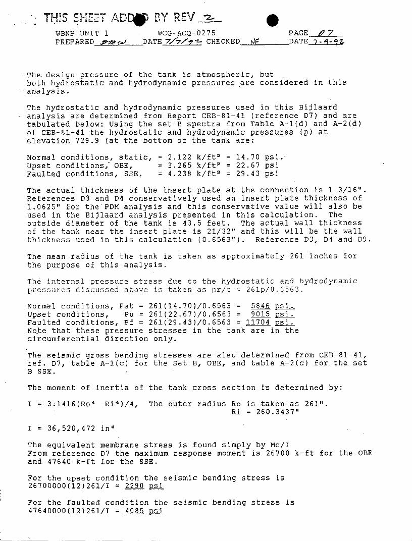
The design pressure of the tank is atmospheric, butboth hydrostatic and hydrodynamic pressures are considered in this.analysis.
The hydrostatic and hydrodynamic pressures used in this Bijlaardanalysis are determined from Report CEB-81-41 (reference D7) and aretabulated below: Using the set B spectra from Table A-1(d) and A-2(d)of CEB-81-41 the hydrostatic and hydrodynamic pressures (p) atelevation 729.9 (at the bottom of the tank are:
Normal conditions, static, = 2.122 k/ft 2 = 14.70 psi.Upset conditions, OBE, = 3.265 k/ft 2 = 22.67 psiFaulted conditions, SSE, = 4.238 k/ft 2 = 29.43 psi
The actual thickness of the insert plate at the connection is 1 3/16".References D3 and D4 conservatively used an insert plate thickness of1.0625" for the PDM analysis and this conservative value will also beused in the Bijlaard analysis presented in this calculation. Theoutside diameter of the tank is 43.5 feet. The actual wall thicknessof the tank near the insert plate is 21/32" and this will be the wallthickness used in this calculation (0.6563"). Reference D3, D4 and D9.
The mean radius of the tank is taken as approximately 261 inches forthe purpose of this analysis.
The internal pressure stress due to the hydrostatic and hydrodynamicpressures discussed above is taken as pr/t = 261p/0.6533.
Normal conditions, Pst = 261(14.70)/0.6563 = 5846 psi.Upset conditions, Pu = 261(22.67)/0.6563 = 9015 psi.Faulted conditions, Pf = 261(29.43)/0.6563 = 11704 psi.Note that these pressure stresses in the tank are in thecircumferential direction only.
The seismic gross bending stresses are also determined from CEB-81-41,ref. D7, table A-l(c) for the Set B, OBE, and table A-2(c) for the setB SSE.
The moment of inertia of the tank cross section is determined by:
I = 3.1416(Ro 4 -Ri4 )/4, The outer radius Ro is taken as 261".Ri = 260.3437"
I = 36,520,472 in'
The equivalent membrane stress is found simply by Mc/IFrom reference D7 the maximum response moment is 26700 k-ft for the OBEand 47640 k-ft for the SSE.
For the upset condition the seismic bending stress is26700000(12)261/I = 2290 Dsi
For the faulted condition the seismic bending stress is47640000(12)261/I = 4085 psi
THIS SHEET ADDS BY REV_-iWBNP UNIT 1 WCG-ACQ-0275 PAGE t7fPREPARED At% DATE -77 -zCHECKED F DATE7
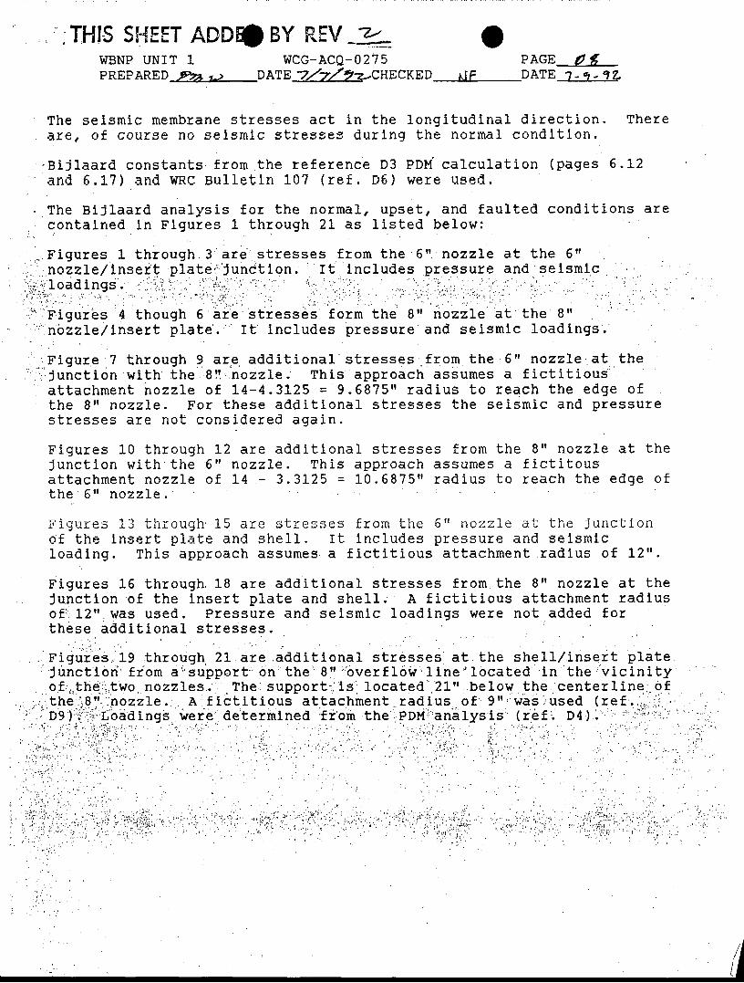
The seismic membrane stresses act in the longitudinal direction. Thereare, of course no seismic stresses during the normal condition.
•-Bijlaard constants from the reference D3 PDM" calculation (pages 6.12and 6.17) and WRC Bulletin 107 (ref. D6) were used.
..The Bijlaard analysis for the normal, upset, and faulted conditions arecontained in Figures 1 through 21 as listed below:
Figures 1 through, 3, are" stresses from the 6". nozzle at the 6"nozzle/insert plate., '.Junction. It includes pressure and seismic
;loadings...
Figures 4 though 6'are stresses form the 8" nozzle at the 8"nozzle/insert plate.e' It includes pressure and seismic loadings'.
Figure 7 through 9 are additional stresses from the 6" nozzle.at the_.junction with the.8!"-nozzle. This approach assumes a fictitiousattachment nozzle of 14-4.3125 = 9.6875" radius to reach the edge ofthe 8" nozzle. For these additional stresses the seismic and pressurestresses are not considered again.
Figures 10 through 12 are additional stresses from the 8" nozzle at thejunction with the 6" nozzle. This approach assumes a fictitousattachment nozzle of 14 - 3.3125 = 10.6875" radius to reach the edge ofthe 6" nozzle.,
Figures 13 through' 15 are stresses from the 6" nozzle at the junctionof the insert plate and shell. It includes pressure and seismicloading. This approach assumes a fictitious attachment radius of 12".
Figures 16 through, 18 are additional stresses from the 8" nozzle at thejunction of the insert plate and shell.- A fictitious attachment radiusof':, 12" was used. Pressure and seismic loadings were not added forthese additional stresses.
,Figures, 19 through 21 are additional stresses at the shell/insert platejunctior from asupport-on"the-8" :overfl6w-line 'located in the/'vicinityof -,the ̀ ,two nozzles. The' support is located 21" ..below the centerline of.the8 nozzle .. A fictitious attachment radius of 9"was.used (refD9)..Loadings Were determined ;from the PDM analysis (ref D4)
. ..... ... ."; "... .. •'' ' .. . .' " '4 '. "" : ... .'. . ' .. . . % ••~ :,: • : % ::

-HS ET ADDED BYWBNP UNIT 1 WCG-ACQ-0275 PAGE. 4PREPARED DATEVeL•_•CHECKED dF DATE-7-!-
The results of the Bijlaard analysis at the nozzle/insert platejunctions are tabulated below and compare the maximum principlestresses with the allowable stresses:
STRESSES AT NOZZLE/INSERT PLATE JUNCTION - PSI(see figures 1 through 12 of this appendix)
ADDITION ADDITION6" @ 6" 8" @ 8" 6" @ 8" 8" @ 6" TOTAL 8" TOTAL 6" ALLOWABLEJUNCTION JUNCTION JUNCTION JUNCTION JUNCTION JUNCTION
NORMALM 6334 6024 535 192 6559 6526 18350M+B 12031 7875 3008 1033 10883 13064 27525UPSETM 10022 9303 1020 304 10323 10326 20185M+B 19881 12230 5712 1625 17942 21506 30278FAULTEDM 13347 12087 1643 400 13730 13747 36700M+B 29561 15934 9218 2130 25152 31691 44040
The stress at the junctions of the nozzles and the insert plate arewell within allowable limits.
This Bijlaard evaluation will also investigate stresses at the junctionof the insert plate and shell. The distance from the center of thenozzle to the edge of the insert plate is 12 inches and this will betaken as the radius of the fictitious attachment radius. The shellvessel thickness T will be taken as 0.6563 inches.
The interaction at the junction of the insert plate and shell will alsoconservatively consider the 45 degree support on the bottom of the 8"overflow line (ref. D9) in this Bijlaard evaluation. The loads areobtained from the PDM analysis reference D4. The support loads areapplied to the shell 21 inches below the centerlinethe 8" pipe. Theload is carried to the shell through a 10 inch diameter, 1/4" pad. Thedistance from the center of the pad to the edge of the insert plate is21 -12 = 9 inches. Therefore a BiJlaard analysis will be performedwith a fictitious attachment radius of 9 inches to conservativelyevaluate the impact of the support on stresses at the insertplate/shell junction.
The loadings from the support are from reference D4 and are listedbelow:
SUPPORT LOADS FROM OVERFLOW LINE(see page D62)
AXIAL SHEAR BENDING TORSIONPx Py, Pz Mby, Mbz Mtx
axial long. circ. circ long torsion(lb) (lb) (in-lb) (in-lb)
Overflow supportNORMAL,actual 2420 2420 0 0 0 0UPSET,actual 3025 3025 0 0 0 0FAULTED,actual 3630 3630 0 0 0 0
The maximum principle stress at the junction of the insert plate andshell are tabulated below. Stresses from the 6" nozzle were calculated
I HIS ASHEET ADDEDOY REV -z-WBNP UNIT 1 WCG-ACQ-0275PREPARED _- DATE -7ý1/7 -.CHECKED
0PAGE ____O
NF DATE j7-,-
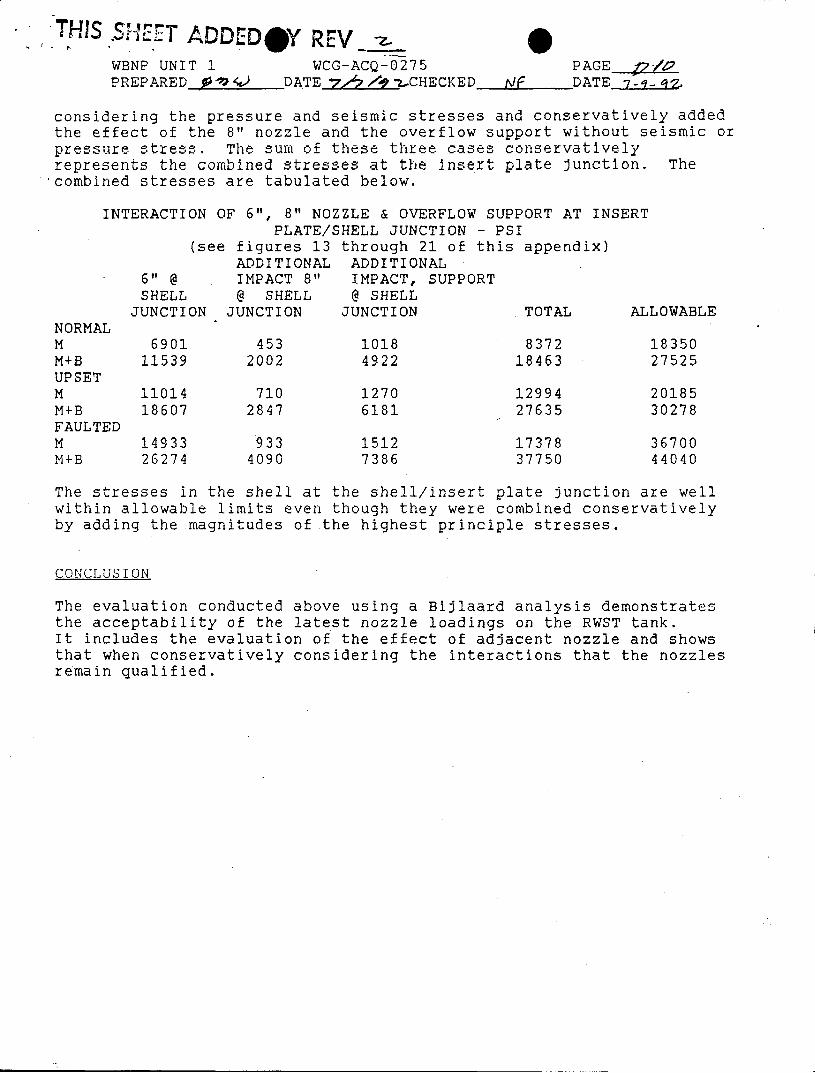
considering the pressure and seismic stresses and conservatively addedthe effect of the 8" nozzle and the overflow support without seismic orpressure stress. The sum of these three cases conservativelyrepresents the combined stresses at the insert plate junction. The'combined stresses are tabulated below.
NORMALMM+BUPSETMM+BFAULTEDMM+B
INTERACTION OF 6", 8" NOZZLE & OVERFLOW SUPPORT AT INSERTPLATE/SHELL JUNCTION - PSI
(see figures 13 through 21 of this appendix)ADDITIONAL ADDITIONAL
6" @ IMPACT 8" IMPACT, SUPPORTSHELL @ SHELL @ SHELLJUNCTION JUNCTION JUNCTION TOTAL AL
690111539
1101418607
1493326274
4532002
7102847
9334090
10184922
12706181
15127386
837218463
1299427635
1737837750
LOWABLE
1835027525
2018530278
3670044040
The stresses in the shell at the shell/insert plate junction are wellwithin allowable limits even though they were combined conservativelyby adding the magnitudes of the highest principle stresses.
CONCLUSION
The evaluation conducted above using a Bijlaard analysis demonstratesthe acceptability of the latest nozzle loadings on the RWST tank.It includes the evaluation of the effect of adjacent nozzle and showsthat when conservatively considering the interactions that the nozzlesremain qualified.