en164: design of computing systems - brown …scale.engin.brown.edu/classes/en164s12/topic03 -...
TRANSCRIPT

EN164: Design of Computing Systems Topic 03: Instruction Set Architecture Design
Professor Sherief Reda http://scale.engin.brown.edu
Electrical Sciences and Computer Engineering School of Engineering
Brown University Spring 2012
1

ISA is the HW/SW interface
2
HW
SW ISA
ISA choice determines:
• program size (& memory size)
• complexity of hardware (CPI and f)
• execution time for different applications and domains
• power consumption
• die area (cost)

Stored program concept (von Neumann model)
3
n Instructions represented in binary numbers, just like data
n Instructions and data stored in memory
n Programs can operate on programs n e.g., compilers, linkers, …
n Binary compatibility allows compiled programs to work on different computers n Standardized ISAs
The BIG Picture
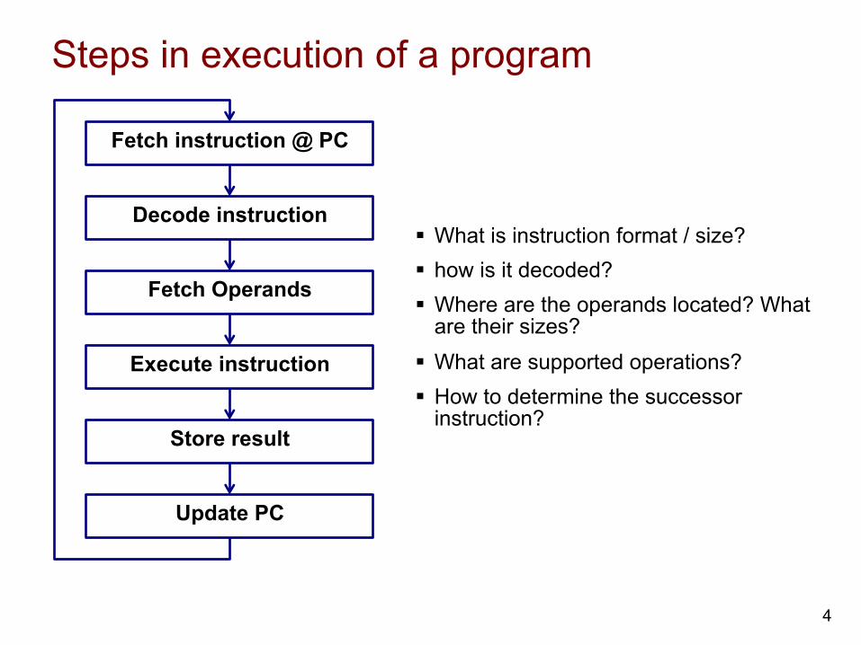
Steps in execution of a program
4
§ What is instruction format / size? § how is it decoded? § Where are the operands located? What
are their sizes? § What are supported operations? § How to determine the successor
instruction?
Fetch instruction @ PC
Decode instruction
Fetch Operands
Execute instruction
Store result
Update PC

Example of an instruction
5
add $t0, $s1, $s2
special $s1 $s2 $t0 0 add
0 17 18 8 0 32
000000 10001 10010 01000 00000 100000
000000100011001001000000001000002 = 0232402016
op rs rt rd shamt funct 6 bits 6 bits 5 bits 5 bits 5 bits 5 bits
assembly language
machine language
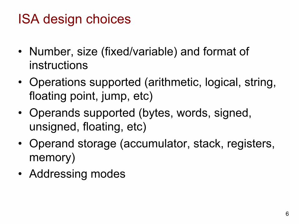
ISA design choices
• Number, size (fixed/variable) and format of instructions
• Operations supported (arithmetic, logical, string, floating point, jump, etc)
• Operands supported (bytes, words, signed, unsigned, floating, etc)
• Operand storage (accumulator, stack, registers, memory)
• Addressing modes
6
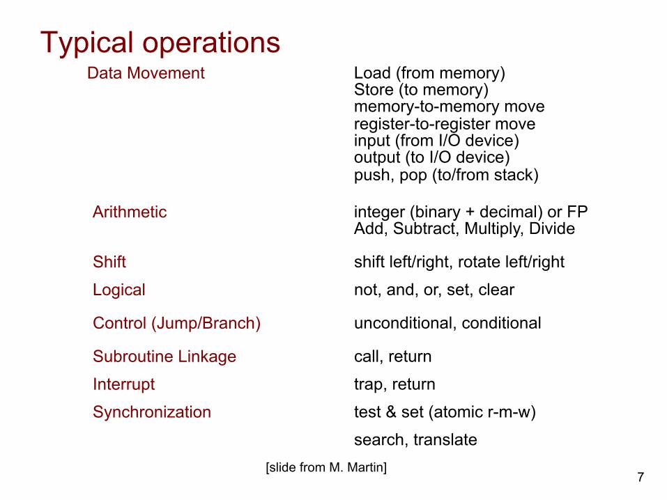
Typical operations
7
Data Movement Load (from memory) Store (to memory) memory-to-memory move register-to-register move input (from I/O device) output (to I/O device) push, pop (to/from stack)
Arithmetic integer (binary + decimal) or FP Add, Subtract, Multiply, Divide
Logical not, and, or, set, clear Shift shift left/right, rotate left/right
Control (Jump/Branch) unconditional, conditional
Subroutine Linkage call, return
Interrupt trap, return
Synchronization test & set (atomic r-m-w)
search, translate [slide from M. Martin]

Classification of ISAs
8
[Figure from D. Brooks -- Harvard]
These ISAs give different characteristics in terms of size of programs, number of instructions and CPI.

Examples of ISA
9
Instruction sequence for C = A + B for the four ISAs
Stack Accumulator Register (register-memory)
Register (load-store)
Push A Push B Add Pop C
Load A Add B Store C
Load R1, A Add R1, B Store C, R1
Load R1, A Load R2, B Add R3, R1, R2 Store C, R3
Some architectures (e.g. x86) support hybrid ISAs for different classes of instructions and/or for backward compatibility.
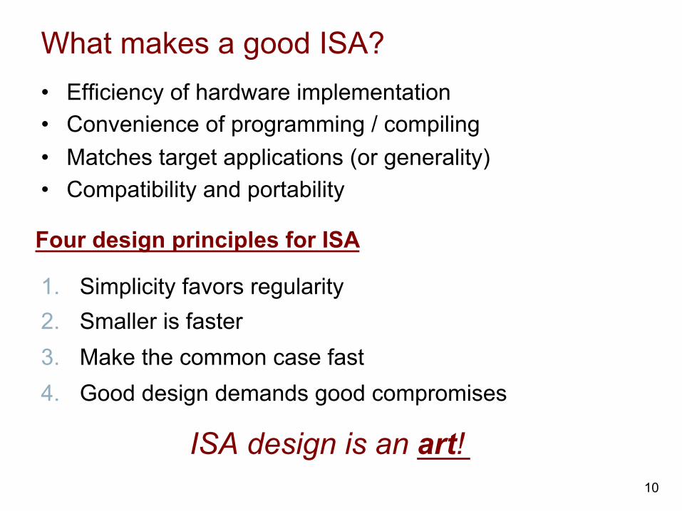
What makes a good ISA? • Efficiency of hardware implementation • Convenience of programming / compiling • Matches target applications (or generality) • Compatibility and portability
10
1. Simplicity favors regularity 2. Smaller is faster 3. Make the common case fast 4. Good design demands good compromises
ISA design is an art!
Four design principles for ISA

Popular ISAs
• x86 from Intel (laptops, servers)
• ARM (mobile devices)
• MIPS (embedded devices)
• Power and PowerPC from IBM (servers, old Macs)
• and many others still spoken and dead ISAs
11

MIPS architecture: Example of Reduced Instruction Set Computer (RISC) architecture • Used as the example throughout the course • Stanford MIPS commercialized by MIPS
Technologies (www.mips.com) • Large share of embedded core market
– Applications in consumer electronics, network/storage equipment, cameras, printers, …
• Typical of many modern ISAs • 32 bit and 64 bit available • Will implement and boot a subset MIPS
processor in lab
12
Arithmetic operations
13
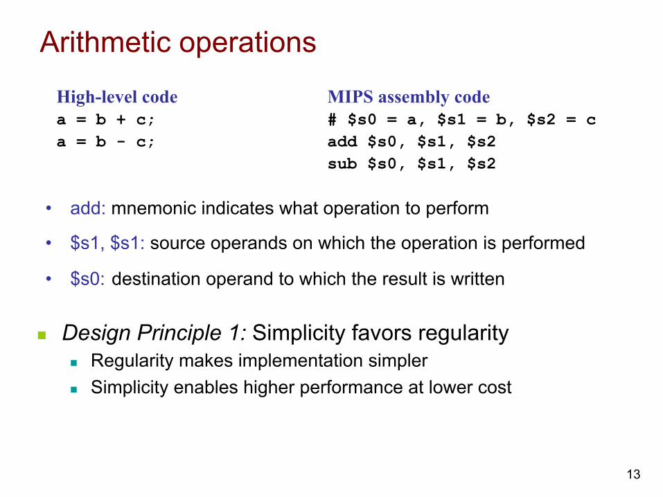
n Design Principle 1: Simplicity favors regularity n Regularity makes implementation simpler n Simplicity enables higher performance at lower cost
High-level code a = b + c; a = b - c;
MIPS assembly code # $s0 = a, $s1 = b, $s2 = c add $s0, $s1, $s2 sub $s0, $s1, $s2
• add: mnemonic indicates what operation to perform
• $s1, $s1: source operands on which the operation is performed
• $s0: destination operand to which the result is written

Register operands
14
• Memory is slow. • Most architectures have a small set of (fast) registers • MIPS has a 32 32-bit register file
n Use for frequently accessed data n Numbered 0 to 31 n 32-bit data called a “word” n Written with a $ before their name
n Assembler names n $0 always hold value 0 n $t0, $t1, …, $t9 for temporary values n $s0, $s1, …, $s7 for saved variables
n Design Principle 2: Smaller is faster n c.f. main memory: millions of locations

MIPS registers
15
Name Register Number Usage $0 0 the constant value 0 $at 1 assembler temporary $v0-$v1 2-3 procedure return values $a0-$a3 4-7 procedure arguments $t0-$t7 8-15 temporaries $s0-$s7 16-23 saved variables $t8-$t9 24-25 more temporaries $k0-$k1 26-27 OS temporaries $gp 28 global pointer $sp 29 stack pointer $fp 30 frame pointer $ra 31 procedure return address

Format of R-type instructions
16
op rs rt rd shamt funct6 bits 5 bits 5 bits 5 bits 5 bits 6 bits
R-Type
• Register-type • 3 register operands:
– rs, rt: source registers – rd: destination register
• Other fields: – op: the operation code or opcode (0 for R-type instructions) – funct: the function
together, the opcode and function tell the computer what operation to perform
– shamt: the shift amount for shift instructions, otherwise it’s 0

R-Type examples
17
add $s0, $s1, $s2
sub $t0, $t3, $t5
Assembly Code
0 17 18 16 0 32
Field Values
0 11 13 8 0 34
op rs rt rd shamt funct
6 bits 5 bits 5 bits 5 bits 5 bits 6 bits
Note the order of registers in the assembly code:
add rd, rs, rt
000000 10001 10010 10000 00000 100000
op rs rt rd shamt funct
000000 01011 01101 01000 00000 100010
Machine Code
6 bits 5 bits 5 bits 5 bits 5 bits 6 bits
(0x02328020)
(0x016D4022)

Memory operands
18
• Too much data to fit in only 32 registers
• Memory is large, but slow
• Commonly used variables kept in registers
• Using a combination of registers and memory, a program can access a large amount of data fairly quickly
• To apply arithmetic operations
n Load values from memory into registers
n Store result from register to memory

Word-addressable memory
19
• Each 32-bit data word has a unique address
Data
00000003 4 0 F 3 0 7 8 8
0 1 E E 2 8 4 2
F 2 F 1 A C 0 7
A B C D E F 7 8
00000002
00000001
00000000
Word Address
Word 3
Word 2
Word 1
Word 0

Reading word-addressable memory
20
• Memory reads are called loads • Mnemonic: load word (lw) • Example: read a word of data at memory address 1 into $s3 • Memory address calculation:
– add the base address ($0) to the offset (1) – address = ($0 + 1) = 1
• Any register may be used to store the base address. • $s3 holds the value 0xF2F1AC07 after the instruction completes.
Data
00000003 4 0 F 3 0 7 8 8
0 1 E E 2 8 4 2
F 2 F 1 A C 0 7
A B C D E F 7 8
00000002
00000001
00000000
Word Address
Word 3
Word 2
Word 1
Word 0
Assembly code lw $s3, 1($0) # read memory word 1 into $s3

Writing word-addressable memory
21
• Memory writes are called stores • Mnemonic: store word (sw) • Example: Write (store) the value held in $t4 into memory address 7 • Offset can be written in decimal (default) or hexadecimal • Memory address calculation:
– add the base address ($0) to the offset (0x7) – address: ($0 + 0x7) = 7
• Any register may be used to store the base address
Data
00000003 4 0 F 3 0 7 8 8
0 1 E E 2 8 4 2
F 2 F 1 A C 0 7
A B C D E F 7 8
00000002
00000001
00000000
Word Address
Word 3
Word 2
Word 1
Word 0
Assembly code sw $t4, 0x7($0) # write the value in $t4 # to memory word 7

Byte-addressable memory
22
• Each data byte has a unique address • Load/store words or single bytes: load byte (lb) and
store byte (sb) • Each 32-bit words has 4 bytes, so the word address
increments by 4
Word Address Data
0000000C
00000008
00000004
00000000
width = 4 bytes
4 0 F 3 0 7 8 8
0 1 E E 2 8 4 2
F 2 F 1 A C 0 7
A B C D E F 7 8
Word 3
Word 2
Word 1
Word 0

Reading byte-addressable memory
23
• The address of a memory word must now be multiplied by 4. For example, – the address of memory word 2 is 2 × 4 = 8 – the address of memory word 10 is 10 × 4 = 40 (0x28)
• Load a word of data at memory address 4 into $s3. • $s3 holds the value 0xF2F1AC07 after the instruction completes. • MIPS is byte-addressed, not word-addressed.
Word Address Data
0000000C
00000008
00000004
00000000
width = 4 bytes
4 0 F 3 0 7 8 8
0 1 E E 2 8 4 2
F 2 F 1 A C 0 7
A B C D E F 7 8
Word 3
Word 2
Word 1
Word 0
MIPS assembly code lw $s3, 4($0) # read word at address 4 into $s3

Writing byte-addressed memory
24
• Example: stores the value held in $t7 into memory address 0x2C (44)
Word Address Data
0000000C
00000008
00000004
00000000
width = 4 bytes
4 0 F 3 0 7 8 8
0 1 E E 2 8 4 2
F 2 F 1 A C 0 7
A B C D E F 7 8
Word 3
Word 2
Word 1
Word 0
MIPS assembly code sw $t7, 44($0) # write $t7 into address 44

Big-Endian and little-Endian
25
• How to number bytes within a word? • Word address is the same for big- or little-endian • Little-endian: byte numbers start at the little (least
significant) end • Big-endian: byte numbers start at the big (most significant)
end
0 1 2 3MSB LSB
4 5 6 78 9 A BC D E F
ByteAddress
3 2 1 007 6 5 44B A 9 88F E D CC
ByteAddress
WordAddress
Big-Endian Little-Endian
MSB LSB
Big- and little- Endian example
26
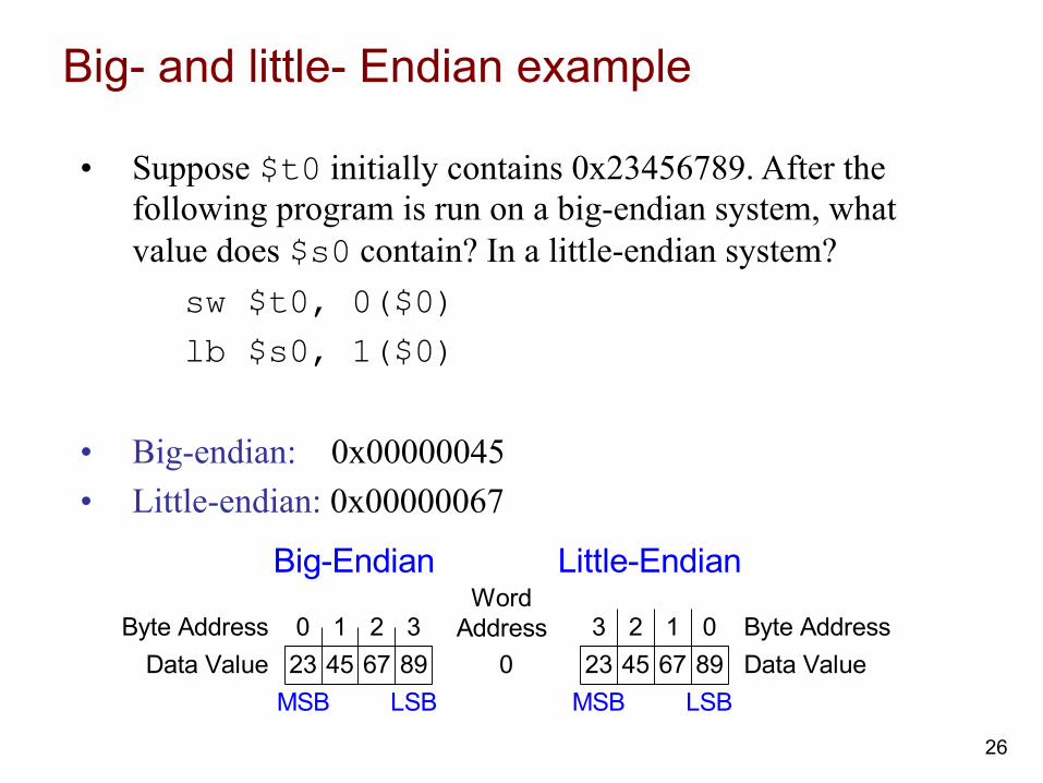
• Suppose $t0 initially contains 0x23456789. After the following program is run on a big-endian system, what value does $s0 contain? In a little-endian system?
sw $t0, 0($0) lb $s0, 1($0)
• Big-endian: 0x00000045 • Little-endian: 0x00000067
23 45 67 890 1 2 3
23 45 67 8903 2 1 0
WordAddress
Big-Endian Little-Endian
Byte AddressData Value
Byte AddressData Value
MSB LSB MSB LSB

Design principle 4 in action
27
Good design demands good compromises - Multiple instruction formats allow flexibility
- add, sub: use 3 register operands
- lw, sw: use 2 register operands and a constant
- Number of instruction formats kept small
- to adhere to design principles 1 and 3 (simplicity favors regularity and smaller is faster).

Constant/Immediate operands
28
• lw and sw illustrate the use of constants or immediates • Called immediates because they are immediately available
from the instruction • Immediates don’t require a register or memory access. • The add immediate (addi) instruction adds an immediate to a
variable (held in a register). • An immediate is a 16-bit two’s complement number. • Is subtract immediate (subi) necessary?
High-level code a = a + 4; b = a – 12;
MIPS assembly code # $s0 = a, $s1 = b addi $s0, $s0, 4 addi $s1, $s0, -12

I-Type format instructions
29
op rs rt imm6 bits 5 bits 5 bits 16 bits
I-Type
• Immediate-type • 3 operands:
– rs, rt: register operands – imm: 16-bit two’s complement immediate
• Other fields: – op: the opcode – Simplicity favors regularity: all instructions have opcode – Operation is completely determined by the opcode

I-Type examples
30
Assembly Code
8 17 16 5
Field Valuesop rs rt imm
6 bits 5 bits 5 bits 16 bits
addi $s0, $s1, 5
addi $t0, $s3, -12
lw $t2, 32($0)
sw $s1, 4($t1)
8 19 8 -12
35 0 10 32
43 9 17 4
(0x22300005)
(0x2268FFF4)
(0x8C0A0020)
(0xAD310004)
001000 10001 10000 0000 0000 0000 0101
op rs rt imm
Machine Code
6 bits 5 bits 5 bits 16 bits
001000 10011 01000 1111 1111 1111 0100
100011 00000 01010 0000 0000 0010 0000
101011 01001 10001 0000 0000 0000 0100
Note the differing order of registers in the assembly and machine codes:
addi rt, rs, imm
lw rt, imm(rs)
sw rt, imm(rs)
Logical operations
31
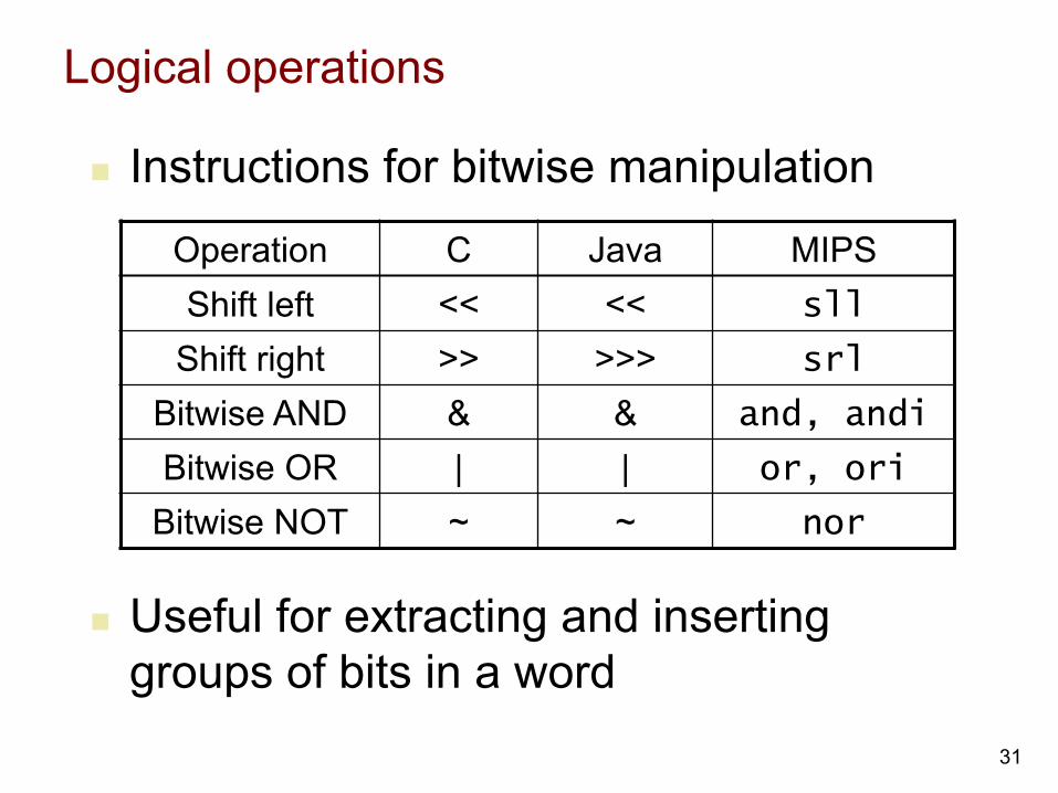
n Instructions for bitwise manipulation
Operation C Java MIPS Shift left << << sll
Shift right >> >>> srl
Bitwise AND & & and, andi
Bitwise OR | | or, ori
Bitwise NOT ~ ~ nor
n Useful for extracting and inserting groups of bits in a word

Shift operations
32
n shamt: how many positions to shift n Shift left logical
n Shift left and fill with 0 bits n sll by i bits multiplies by 2i
n Shift right logical n Shift right and fill with 0 bits n srl by i bits divides by 2i (unsigned only)
op rs rt rd shamt funct 6 bits 6 bits 5 bits 5 bits 5 bits 5 bits

AND operations
33
n Useful to mask bits in a word n Select some bits, clear others to 0
and $t0, $t1, $t2
0000 0000 0000 0000 0000 1101 1100 0000
0000 0000 0000 0000 0011 1100 0000 0000
$t2
$t1
0000 0000 0000 0000 0000 1100 0000 0000 $t0

OR operations
34
n Useful to include bits in a word n Set some bits to 1, leave others unchanged
or $t0, $t1, $t2
n Useful to include bits in a word n Set some bits to 1, leave others unchanged
or $t0, $t1, $t2
0000 0000 0000 0000 0000 1101 1100 0000
0000 0000 0000 0000 0011 1100 0000 0000
$t2
$t1
0000 0000 0000 0000 0011 1101 1100 0000 $t0

NOT operations
35
n Useful to invert bits in a word n Change 0 to 1, and 1 to 0
n MIPS has NOR 3-operand instruction n a NOR b == NOT ( a OR b )
nor $t0, $t1, $zero
0000 0000 0000 0000 0011 1100 0000 0000 $t1
1111 1111 1111 1111 1100 0011 1111 1111 $t0
Register 0: always read as zero

Conditional operators
36
n Branch to a labeled instruction if a condition is true n Otherwise, continue sequentially
n beq rs, rt, L1 n if (rs == rt) branch to instruction labeled L1;
n bne rs, rt, L1 n if (rs != rt) branch to instruction labeled L1;
n j L1 n unconditional jump to instruction labeled L1

Compiling if statement
37
n C code: if (i==j) f = g+h; else f = g-h;
n f, g, … in $s0, $s1, … n Compiled MIPS code: bne $s3, $s4, Else add $s0, $s1, $s2 j Exit Else: sub $s0, $s1, $s2 Exit: …

Compiling loop statements
38
n C code: while (save[i] == k) i += 1;
n i in $s3, k in $s5, address of save in $s6 n Compiled MIPS code: Loop: sll $t1, $s3, 2 add $t1, $t1, $s6 lw $t0, 0($t1) bne $t0, $s5, Exit addi $s3, $s3, 1 j Loop Exit: …

More conditional operations
39
n Set result to 1 if a condition is true n Otherwise, set to 0
n slt rd, rs, rt
n if (rs < rt) rd = 1; else rd = 0; n slti rt, rs, constant
n if (rs < constant) rt = 1; else rt = 0; n Use in combination with beq, bne
slt $t0, $s1, $s2 # if ($s1 < $s2) bne $t0, $zero, L # branch to L

Branch instruction design
40
n Why not blt, bge, etc? n Hardware for <, ≥, … slower than =, ≠
n Combining with branch involves more work per instruction, requiring a slower clock
n All instructions penalized! n beq and bne are the common case n This is a good design compromise

Summary of instruction formats
41
op rs rt rd shamt funct6 bits 5 bits 5 bits 5 bits 5 bits 6 bits
R-Type
op rs rt imm6 bits 5 bits 5 bits 16 bits
I-Type
op addr6 bits 26 bits
J-Type

Procedure calls
42
Procedure calling conventions: • Caller:
– passes arguments to callee. – jumps to the callee
• Callee: – performs the procedure – returns the result to caller – returns to the point of call – must not overwrite registers or memory needed by the caller
MIPS conventions: • Call procedure: jump and link (jal) • Return from procedure: jump register (jr) • Argument values: $a0 - $a3 • Return value: $v0 -$v1

Procedure calls
43
High-level code int main() { simple(); a = b + c; } void simple() { return; }
MIPS assembly code 0x00400200 main: jal simple 0x00400204 add $s0, $s1, $s2 ... 0x00401020 simple: jr $ra
void means that simple doesn’t return a value.
jal: jumps to simple and saves PC+4 in the return address register ($ra). In this case, $ra = 0x00400204 after jal executes.
jr $ra: jumps to address in $ra, in this case 0x00400204.

Input arguments and return values
44
High-level code int main()
{
int y;
...
y = diffofsums(2, 3, 4, 5); // 4 arguments
...
}
int diffofsums(int f, int g, int h, int i)
{
int result;
result = (f + g) - (h + i);
return result; // return value
}

Input arguments and return values
45
MIPS conventions: • Argument values: $a0 - $a3 • Return value: $v0
MIPS assembly code main: ... addi $a0, $0, 2 # argument 0 = 2 addi $a1, $0, 3 # argument 1 = 3 addi $a2, $0, 4 # argument 2 = 4 addi $a3, $0, 5 # argument 3 = 5 jal diffofsums # call procedure add $s0, $v0, $0 # y = returned value ... # $s0 = result diffofsums: add $t0, $a0, $a1 # $t0 = f + g add $t1, $a2, $a3 # $t1 = h + i sub $s0, $t0, $t1 # result = (f + g) - (h + i) add $v0, $s0, $0 # put return value in $v0 jr $ra # return to caller

Potential problems in procedural calling
46
MIPS assembly code # $s0 = result diffofsums: add $t0, $a0, $a1 # $t0 = f + g add $t1, $a2, $a3 # $t1 = h + i sub $s0, $t0, $t1 # result = (f + g) - (h + i) add $v0, $s0, $0 # put return value in $v0 jr $ra # return to caller
• diffofsums overwrote 3 registers: $t0, $t1, and $s0 • diffofsums can use the stack to temporarily store registers

The stack
47
• Memory used to temporarily save variables • Like a stack of dishes, last-in-first-out (LIFO) queue • Expands: uses more memory by growing down (from
higher to lower memory addresses) when more space is needed
• Contracts: uses less memory when the space is no longer needed
• Stack pointer: $sp, points to top of the stack Data
7FFFFFFC 12345678
7FFFFFF8
7FFFFFF4
7FFFFFF0
Address
$sp 7FFFFFFC
7FFFFFF8
7FFFFFF4
7FFFFFF0
Address Data
12345678
$sp
AABBCCDD
11223344
How procedures use the stack
48
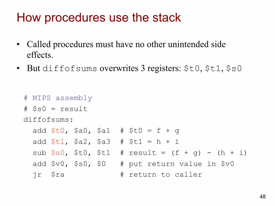
# MIPS assembly
# $s0 = result diffofsums:
add $t0, $a0, $a1 # $t0 = f + g
add $t1, $a2, $a3 # $t1 = h + i
sub $s0, $t0, $t1 # result = (f + g) - (h + i)
add $v0, $s0, $0 # put return value in $v0 jr $ra # return to caller
• Called procedures must have no other unintended side effects.
• But diffofsums overwrites 3 registers: $t0, $t1, $s0
Storing register values on the stack
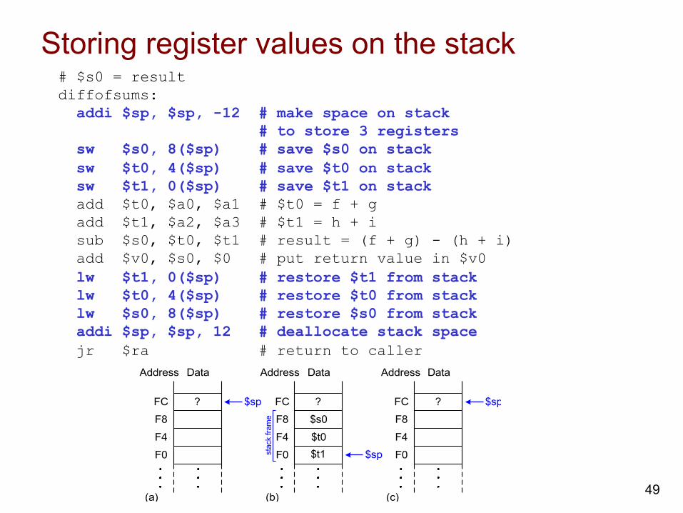
49
# $s0 = result diffofsums: addi $sp, $sp, -12 # make space on stack # to store 3 registers sw $s0, 8($sp) # save $s0 on stack sw $t0, 4($sp) # save $t0 on stack sw $t1, 0($sp) # save $t1 on stack add $t0, $a0, $a1 # $t0 = f + g add $t1, $a2, $a3 # $t1 = h + i sub $s0, $t0, $t1 # result = (f + g) - (h + i) add $v0, $s0, $0 # put return value in $v0 lw $t1, 0($sp) # restore $t1 from stack lw $t0, 4($sp) # restore $t0 from stack lw $s0, 8($sp) # restore $s0 from stack addi $sp, $sp, 12 # deallocate stack space jr $ra # return to caller Data
FC
F8
F4
F0
Address
$sp
(a)
Data
FC
F8
F4
F0
Address
$sp
(b)
$s0
Data
$sp
(c)
$t0
FC
F8
F4
F0
Address
? ??
stac
k fra
me
$t1

Protocol for preserving registers
50
Preserved Callee-Saved
Nonpreserved Caller-Saved
$s0 - $s7 $t0 - $t9
$ra $a0 - $a3
$sp $v0 - $v1
stack above $sp stack below $sp

Multiple procedure calls
51
proc1:
addi $sp, $sp, -4 # make space on stack sw $ra, 0($sp) # save $ra on stack jal proc2
...
lw $ra, 0($sp) # restore $s0 from stack addi $sp, $sp, 4 # deallocate stack space jr $ra # return to caller

Storing saved registers on the stack
52
# $s0 = result
diffofsums: addi $sp, $sp, -4 # make space on stack to # store one register
sw $s0, 0($sp) # save $s0 on stack # no need to save $t0 or $t1 add $t0, $a0, $a1 # $t0 = f + g add $t1, $a2, $a3 # $t1 = h + i
sub $s0, $t0, $t1 # result = (f + g) - (h + i)
add $v0, $s0, $0 # put return value in $v0
lw $s0, 0($sp) # restore $s0 from stack addi $sp, $sp, 4 # deallocate stack space jr $ra # return to caller

Recursive procedure calls
53
High-level code int factorial(int n) { if (n <= 1) return 1; else return (n * factorial(n-1)); }

Recursive procedure calls
54
MIPS assembly code 0x90 factorial: addi $sp, $sp, -8 # make room 0x94 sw $a0, 4($sp) # store $a0 0x98 sw $ra, 0($sp) # store $ra 0x9C addi $t0, $0, 2 0xA0 slt $t0, $a0, $t0 # a <= 1 ? 0xA4 beq $t0, $0, else # no: go to else 0xA8 addi $v0, $0, 1 # yes: return 1 0xAC addi $sp, $sp, 8 # restore $sp 0xB0 jr $ra # return 0xB4 else: addi $a0, $a0, -1 # n = n - 1 0xB8 jal factorial # recursive call 0xBC lw $ra, 0($sp) # restore $ra 0xC0 lw $a0, 4($sp) # restore $a0 0xC4 addi $sp, $sp, 8 # restore $sp 0xC8 mul $v0, $a0, $v0 # n * factorial(n-1) 0xCC jr $ra # return

Stack during recursive calls
55
$sp FC
F8
F4
F0
$ra
EC
E8
E4
E0
DC
FC
F8
F4
F0
EC
E8
E4
E0
DC
FC
F8
F4
F0
EC
E8
E4
E0
DC
$sp
$sp
$sp
$sp
$a0 = 1$v0 = 1 x 1
$a0 = 2$v0 = 2 x 1
$a0 = 3$v0 = 3 x 2
$v0 = 6
$sp
$sp
$sp
$sp
DataAddress DataAddress DataAddress
$a0 (0x3)
$ra (0xBC)
$a0 (0x2)
$ra (0xBC)
$a0 (0x1)
$ra
$a0 (0x3)
$ra (0xBC)
$a0 (0x2)
$ra (0xBC)
$a0 (0x1)

Procedural call summary
56
• Caller – Put arguments in $a0-$a3 – Save any registers that are needed ($ra, maybe $t0-t9) – jal callee – Restore registers – Look for result in $v0
• Callee – Save registers that might be disturbed ($s0-$s7) – Perform procedure – Put result in $v0 – Restore registers – jr $ra

x86 ISA: Example of Complex Instruction Set Computer (CISC) architecture
57
x86 instruction set
n Backward compatibility ⇒ instruction set doesn’t change n But they do accumulate more instructions
° Rank instruction Integer Average Percent total executed1 load 22%2 conditional branch 20%3 compare 16%4 store 12%5 add 8%6 and 6%7 sub 5%8 move register-register 4%9 call 1%10 return 1%
Total 96%° Simple instructions dominate instruction frequency

x86 registers
58
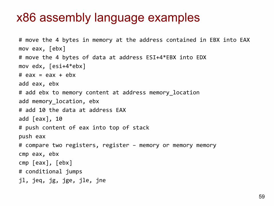
x86 assembly language examples
59
# move the 4 bytes in memory at the address contained in EBX into EAX mov eax, [ebx] # move the 4 bytes of data at address ESI+4*EBX into EDX mov edx, [esi+4*ebx] # eax = eax + ebx add eax, ebx # add ebx to memory content at address memory_location add memory_location, ebx # add 10 the data at address EAX add [eax], 10 # push content of eax into top of stack push eax # compare two registers, register – memory or memory memory cmp eax, ebx cmp [eax], [ebx] # conditional jumps jl, jeq, jg, jge, jle, jne