en user manual -...
TRANSCRIPT

USER MANUAL Easy Link PLUS SeriesDefault user name: admin Default password: 123456
EN

2Easy Link PLUS Series DVR
About this ManualThe material in this document is for information purpose and is subject to change without prior notice. We made every effort to ensure that this user’s manual is accurate and complete. However, no liability is assumed for any errors and omissions that may have occurred.
FCC Compliance StatementThis equipment has been tested and found to comply with the limits for a Class B digital device, pursuant to Part 15 of the FCC Rules. These limits are designed to provide reasonable protection against harmful interference in a residential installation. This equipment generates uses and can radiate radio frequency energy and, if not installed and used in accordance with the instructions, may cause harmful interference to radio communications. However, there is no guarantee that interference will not occur in a particular installation. If this equipment does cause harmful interference to radio or television reception, which can be determined by turning the equipment off and on, the user is encouraged to try to correct the interference by one or more of the following measures:
• Reorient or relocate the receiving antenna.
• Increase the separation between the product and receiver.
• Connect the product into an outlet on a circuit different from that to which the receiver is connected.
• Consult the dealer or an experienced radio/TV technician for help.
• Declaration of Conformity
Declaration of ConformityThis device complies with part 15 of the FCC Rules. Operation is subject to the following two conditions:1. This device may not cause harmful interference.2. This device must accept any interference received, including interference that may cause undesired operation.
Copyright
Limitation of Liability• This publication is provided “AS IS” without warranty of any kind, either expressed or
implied, including but not limited to, the implied warranties of merchantability, fitness for any particular purpose, or non-infringement of a third party’s rights.
• This publication may include technical inaccuracies or typographical errors. Changes may be made to the information herein, at any time, for publication improvements and/or of the corresponding device(s).
Disclaimer of WarrantyIn no event shall the supplier be liable to any party or any person, except for replacement or reasonable maintenance of the product, for the cases, including but not limited to the following:
• Any damage or loss, including but without limitation, direct or indirect, special, consequential or exemplary, arising out of or relating to the device;
• Personal injury or any damage caused by inappropriate use or negligent operation of the user;
• Unauthorized disassemble, repair or modification of the device by the user;
• Any problem, consequential inconvenience, or loss or damage, arising out of combining the system with the devices of a third party;
• Any claim or action for damages, brought by any person or organization being a photogenic subject, due to violation of privacy with the result of pictures from a surveillance camera, including saved data, for some reason, becomes public or is used for the purpose other than for surveillance.
Safety Information
WarningThis is the symbol for indicating any potential hazard, risk or condition requiring special attention. The user needs to refer to the important operating and maintenance or servicing instructions.
CautionThe lighting flash with an arrow head symbol, in an equilateral triangle, is intended to alert the user. There is dangerous “voltage” presence near by the product’s enclosure which may be risk of person.

Easy Link PLUS Series DVR3
Safety Precautions• Do not touch live electrical parts.
Electric shock can be avoided. Follow the recommended practices listed below. Faulty installation, improper grounding, and incorrect operation and maintenance of electrical equipment are always sources of danger.
• Do not try to install equipment outdoor, during strong wind and rain.
• Do not install or remove equipment outdoor, when raining.
• Do not try to install or operate any equipment, during a thunderstorm.
• Always ground all electrical equipment and the work platform. Prevent accidental electrical shocks. Connect power source, control cabinets, and work platform to an approved electrical ground.
• Always use the correct cable size. Sustained overloading will cause cable failure and result in possible electrical shock or fire hazard. Work cable should be the same rating as the factory.
• Always keep cables and connectors in good condition. Improper or worn electrical connections can cause short circuits and can increase the chance of an electrical shock. Do not use worn, damaged, or bare cables.
• Always avoid open-circuit voltage. The added voltages increase the severity of electric shock hazard.
• Always wear insulated gloves while you adjust equipment. Electric power should be turned off and insulated gloves should be worn when making any equipment adjustment to assure shock protection.
• Always wear protective clothing such as long sleeve shirts while you are installing or removing equipment.
• Always wear high, snug fitting shoes.
• Always wear clean clothes without grease or oil.
• Protect neighboring workers from exposure to arc radiation.
• Always wear long trousers or jeans while you are installing or removing equipment.
• Always wear safety helmet or hard hat and safety shoes before work.
• Always keep the equipment in dry places.
• Always wear safety harnesses/belt while you work in high places.
• Always wear dry clothing and avoid moisture and water.
• Always wear Public Safety Vest, while you work at night.
• Make sure all electrical connections are tight, clean, and dry.
• Make sure that you are well insulated to eliminate electric static charge.
• Always wear dry gloves, rubber-soled shoes, or stand on a dry board or platform.
• Always follow recognized safety standards.
• Always wear correct eye, ear, and body protection.
• Always have second person on-site, while you work in dark, poor ventilation, or high places.
• Make sure that you are well protected against arc flashes, mechanical injury, or other mishaps.
• Make sure that the polarity of wire is correct before installing equipment.
• Always handle equipment with care.
• Do not block the ventilation of equipment.
• Do not put the magnetic parts around the equipment.
• Do not put the objects on top of the equipment.

4Easy Link PLUS Series DVR
Record Search: General (continued) .................................. 27
Device: HDD & PTZ ........................................................... 28
System: General & Users .................................................. 29
System: DST & NTP ........................................................... 30
System: Info & Log ............................................................ 31
Advanced: Maintain ......................................................... 32
Advanced: Events & Auto Upgrade ................................... 33
Remote Access via Web Client .......................................... 34
Remote Access via Web Client (continued) ....................... 35
Troubleshooting ............................................................... 36
Table of Contents
Install the Hard Disk Drive .................................................. 5
Making the Connections ..................................................... 6
Common DVR Operations ................................................... 8
Live Viewing Screen ............................................................ 9
Main Menu .......................................................................10
Display: Live ......................................................................11
Display: Output .................................................................12
Display: Privacy Zone .........................................................13
Record: Record & Mainstream ...........................................14
Record: Schedule ...............................................................15
Network: Network .............................................................16
Network: Network & Substream ........................................17
Network: Email & Email Schedule ......................................18
Network: DDNS & FTP .......................................................19
Alarm: Motion ...................................................................20
Alarm: Alarm Kit ................................................................21
Alarm: Alarm Kit & Siren Schedule .....................................22
Record Search: General .....................................................23
Record Search: General & Events .......................................24
Record Search: General (continued) ...................................25
Record Search: General (continued) ...................................26

Easy Link PLUS Series DVR5
Install the Hard Disk DriveThis DVR supports one 3.5” or 2.5” SATA HDD.
CAUTION: DO NOT install or remove the hard disk drive while the device power is turned ON.
The installation procedure of the hard disk drive is slightly different when installing to the 4-channel DVR or to the 8/16-channel DVR. Please see the installation details as follows:
NOTE: Depending on the model you purchased, the actual product may slightly differ from the images below.
4/8/16-Channel DVR
a) Connect the data and power cables to the HDD and place the HDD on the DVR case.
4-Channel DVR
8/16-Channel DVRa) Aligning the connectors on the HDD with the connectors on the motherboard, place the HDD on the DVR case. Then push to make the connection.
b) Carefully flip the DVR case and secure the HDD to the DVR with the four (4) screws.

6Easy Link PLUS Series DVR
A) HDD LED - This will flash when the hard drive is working.
B) Power LED - This light will turn on when the DVR has power.
C) USB - Connect the supplied mouse here.
D) Audio Out - For connecting speakers.
E) Video In - This is where you connect the cameras.
NOTE: To ensure the image quality, we recommend you to use the supplied KGUARD cameras, or purchase separately the PLUS Series KGUARD 720P Megapixel Cameras, such as WA713APK or DA713FPK.
F) Audio In - For connecting microphones.
G) HDMI - Connect this to your digital TV or monitor with HDMI input (HDMI cable included).
H) VGA - Connect this to your TV or a monitor with VGA input.
I) LAN - Connect this to your home network, so your DVR can connect to the Internet.
J) USB - Connect the USB Flash Drive to backup recorded events.
K) Alarm Antenna In (RJ9) - Alarm antenna connects here. The alarm antenna communicates with the wireless alarm sensors, sirens and key fobs.
NOTE: This feature requires purchasing separately the PLUS Series KGUARD Wireless Alarm Kit. For example, model number DSH-002, including Wireless Alarm Antenna, Window/Door Sensor, PIR Motion Sensor, Siren, Key Fob, etc.
L) Power - This is where you connect the power adapter.
Product Overview
NOTE: The front view of the product is similar for 4-channel, 8-channel, and 16-channel DVR.
A B
C
Front View (4-Channel DVR*)
VGA RJ9
12V
LANCAUTIONRISK OF ELECTRIC SHOCK
DO NOT OPEN
HDMIAUDIOOUTPUT
1
2
3
4
1
2
3
4VIDEOINPUT
AUDIOINPUT
D E F G H I K LJ
Rear View (4-Channel DVR)
VGA RJ9
12V
LANCAUTIONRISK OF ELECTRIC SHOCK
DO NOT OPEN
HDMIAUDIOOUTPUT
1
2
3
4
5
6
7
8
1
2
3
4 VIDEOINPUT
AUDIOINPUT
D EF G H I K LJ
Rear View (8-Channel DVR)
VGA
RJ9
12V
LAN
HDMIAUDIOOUTPUT
1357
2468
1
2
3
4VIDEO INPUT
9111315
10121416AUDIOINPUT
DEF GH I K LJ
Rear View (16-Channel DVR)
Making the Connections

Easy Link PLUS Series DVR7
Connection Diagram
VGA RJ9
12V
LANCAUTIONRISK OF ELECTRIC SHOCK
DO NOT OPEN
HDMIAUDIOOUTPUT
1
2
3
4
1
2
3
4VIDEOINPUT
AUDIOINPUT
Internet
or
Notebook/PC
Tablet PC
Smart Phones
Wireless Alarm Devices of PLUS Series (sensors, sirens, key fobs, etc.)
Wireless AlarmAntenna
Front Rear
3
5
21
46
7
1) Connect the microphone(s) and/or audio-supported camera(s), if you want to listen to the audio sound from the cameras.
2) Connect one end of the supplied RJ-45 cable to the router and the other end to the LAN connector on the rear of the DVR.
3) Use the USB flash disk for backup or system upgrade.
4) Connect the video output of the DVR to the TV or monitor via HDMI or VGA connection.
5) Connect the BNC plug of the camera’s extension cable to the Video input connector on the rear of the DVR.
6) Connect speakers if you want to listen to the live audio sound or audio playback from the DVR.
7) You need the USB mouse to go through the initial setup menus once the DVR is powered on.

8Easy Link PLUS Series DVR
Locking the ScreenThe screen is locked to protect unauthorized OSD operation. To access the OSD menu, you need to authenticate yourself by providing the user name and password.
The default user name and password are as below:
• User name: admin • Password: 123456
NOTE: If necessary, you can also lock the screen manually. To do so, right-click on the Live Viewing screen to make the Pop-up menu bar visible. Then click .
Rebooting/Shutting Down the DVRRebooting and shutting down operations can be performed via the Main Menu.
Using the Supplied Mouse
AB
A) Left Button B) Right Button
- Click once to choose an item in the menus and confirm your selection.
- Click once to open the pop-up menu on the Live Viewing screen and to exit from the menus.- Double-click on the channel on the
Live Viewing screen to view the channel in full screen mode. Double- click again to exit the full screen mode.
- Click and hold to drag an area on motion mode or adjust the values of sliders and scales on menu mode.
Using the Virtual KeyboardYou will see the virtual keyboard automatically on the screen anytime you need to enter data.
Click to delete a character
Click to enter the textClick to toggle the keyboard to upper case
Common DVR Operations

Easy Link PLUS Series DVR9
Live Viewing ScreenFirst screen you see after going through or skipping the Startup Wizard. On this screen you see the live views from all connected cameras. The view varies depending on the DVR model you purchased.
A B C D E F G H I J K L M
N O P Q R
Status Icons
Menu bar
Quick Camera Toolbar
Status Icons
Menu BarA) Open the Main Menu
B) Click this to lock the screen
C) Four camera view
D) Nine camera view
E) Twelve camera view
F) Sixteen camera view
G) Click this to view more layout options
H) Click this to start viewing channels in a sequence set in Parameter > Output > View Setup (Dynamic) > Sequence Mode and SEQ Time.
I) Click this to adjust the volume
J) Click this to start / stop cruise for a PTZ camera.
NOTE: This feature is not supported .
K) Click this to enable picture-in-picture when viewing multiple cameras. When enabled, one camera will be displayed in full screen while the other camera will be displayed in a small window.
L) Same with the item “K” but instead of one camera being displayed in a small window, this options displays two cameras in small windows.
M) Click this if you want to playback videos.
M The motion icon indicates that the DVR is detecting motion from the camera. N) Click to start recording the channel manually.
H The HDD icon indicates that the DVR cannot detect a HDD or the HDD is not formatted. O) Open instant playback of the channel.
R This indicates that the DVR is currently recording. P) Click to zoom in the channel.
A This icon appears when wireless alarm devices have triggered recording. Q) Click to adjust the channel color settings.
M This icon appears when the camera has detected motion and triggers recording. R) Click to configure the camera PTZ settings.
VIDEO LOSS: Camera is not connected to the DVR. NOTE: This feature is not supported .

10Easy Link PLUS Series DVR
Main Menu
A) Alarm - Select this menu option to set the motion area and sensitivity, and configure the alarm kit settings.
B) Network - Select this menu option to configure the DVR remote connection parameters.
C) Record - Select this menu option to configure the recording options and set the recording schedule.
D) Display - Select this menu option to configure how channels are displayed on the Live Viewing screen, for example color setup, video output resolution, privacy areas, etc.
E) Record Search - Select this menu option to search for recordings, and events.
F) Device - Select this menu option to format the internal HDD here, view available space, and set overwrite options.
G) System - Select this menu option to modify general DVR settings, such as date and time, etc.
H) Advanced - Select this menu option to modify maintenance tasks and update the system.
I) Shutdown - Select this menu option to shutdown or reboot the DVR here.
J) Copy (Parameters) To - Click to copy the current settings to all channels or one specific channel.
K) Default - Click to restore the default settings.
L) Save - Click to save the modifications.
M) Cancel - Click to discard the modifications.
A
B
C
D
E F G H I
J
K L M

Easy Link PLUS Series DVR11
Display: Live• Channel: Select the channel you want to modify.
• Channel Name: Enter the name of the channel. By default the channel name is “CH#” where “#” is the channel number.
• Position: Select where you want the channel name to be displayed when you are viewing the channel. For example, “Left-Top” means the name is displayed on the “Upper-Left” side of the channel.
• Color: Click Setup to configure video color settings.
BRIGHT: Defines how bright the image appears on the display.
CONTRAST: Increases the difference between the darkest black and the whitest white in the image. Modify the contrast if the sections of the image look “grey out”.
HUE: Changes the color mix of the image.
SATURATION: Alters how much color is displayed in the image. The higher the saturation, the brighter and vivid colors will appear to be. Setting this parameter too high can degrade the image quality.
• Covert: Enable if you want to hide this channel from appearing on the Live Viewing screen. Disabling or enabling this option does not affect video recording on the HDD.
• Record Time: Disable if you do not want to see the recording time on the channel.
• Show Time: Disable if you do not want the current time to appear on the channel.

12Easy Link PLUS Series DVR
Display: Output• Video Output: This is the monitor that you use for live view display.
• View SetUp: Here you can choose how you want the channels to be displayed on live view. Static: Choose this option if you want only selected channels to be displayed. In View Mode choose how many channels you want to include. Then click Define SEQ Setting and choose the channels from the drop down menu.
Dynamic: Choose this option if you want to view all the channels in a sequence. The DVR has a set of predefined layouts on how the channels are displayed. Choose your favorite layout in Sequence Mode menu option.
• SEQ Time: Set how long you want the live view from a channel to be displayed in a sequence.
• VGA/HDMI Resolution: Select the highest resolution your monitor/TV supports. The higher the resolution, the more details you will see on your images. The DVR will restart after you change the resolution.
• Transparency: Decide how transparent you want the menus to be. Choose partially transparent (see-through) if you need to keep an eye on happenings while adjusting settings.

Easy Link PLUS Series DVR13
Display: Privacy ZoneNOTE: Create Privacy Zone(s) if you want to partially cover up your image. You can create up to four privacy zones. On your image, they appear as “black areas”. You can choose where you want to create the zone(s) and how large the zone(s) are. Just click inside the default red-lined rectangle and drag it where you want to create a privacy zone. Then click and hold the red line and move the cursor to give the desired shape for the zone. Right-click to return to the Privacy Zone menu.
• Channel: Select the channel(s) where you want to set privacy zone(s).
• Privacy Zone: You need to enable this function to set privacy areas.
• Area Setup: Decide how many privacy areas you want to set and check the area(s).
• Mask Area: Click Setup to open the channel in full screen mode and start marking the privacy zones. Depending on the number of areas you have chosen in Area Setup, you will see areas covered with black rectangles on the channel view. When you have finished marking the areas, right-click to return to the Main Menu.
NOTE: The privacy zone(s) are not visible on channel live view as well as on the video file. On live view and video file, you can see the privacy zone(s) covered with black boxes.

14Easy Link PLUS Series DVR
Record: Record & Mainstream• Channel: Select the channel to set its recording parameters.
• Record Switch: Enable in order to allow the video to be recorded to the HDD.
• Pre-Record: If this option is enabled, the DVR starts recording a few seconds before an event occurs. Use this option if your primary recording type is motion based.
Configure the recorded video parameters here. All the modifications you apply to these settings will affect the recorded video saved into the HDD.
• Channel: Select the channel to configure recording related information.
• Resolution: This parameter defines, how large the recorded images will be. The available options include: 720P (1280x720) or WD1 (960×480), WHD1 (960×240), WCIF (480×240).
• FPS: This parameter defines the number of frames per second the DVR will record.
• Bitrate: This parameter corresponds to the speed of data transfer that the DVR will use to record video. Recordings that are encoded at higher bitrates, will be of better quality.Audio: Select this option if you want to record audio along with video and have a microphone connected to the DVR or using a camera with audio capablility (not included). Since the audio option is only available for the channels 1 to 4, you need to connect a camera with audio capability to these channels.

Easy Link PLUS Series DVR15
Record: ScheduleThis menu allows you to specify when the DVR records video and define the recording mode for each channel. The recording schedule lets you set up a schedule like, daily and hourly by normal (continuous) recording and motion recording. To set the recording mode, click first on the mode (Normal Record/ Motion Record), then drag the cursor to mark the slots. The recording schedule is valid only for one channel. If you want to use the same recording schedule for other channels, use Copy To function.
The image on the left side shows a recording schedule defined for Channel 1. According to this example schedule, Channel 1 would -
- On Saturday and Sunday record based on Motion 24 hours.- From Monday to Friday record continuously from 6AM to 8PM and motion based from 8PM to 6AM.
• Channel: Select the channel to set its recording parameters.
• Normal Record: When the time slot is marked green, this indicates the channel performs normal recording for that time slot.
• Motion Record: When the time slot is marked yellow, this indicates the channel records only when a motion is detected during that time slot. We recommend to use this type of recording.
• No Record: A time slot marked black means that there is no recording scheduled for the time slot.

16Easy Link PLUS Series DVR
Network: NetworkThe most common types are DHCP or Static. Most probably your network type is DHCP, unless the network is manually addressed (usually called- Static). If you need an authentication user name and password to the Internet, then choose PPPoE.
• Network Type: Select the network type you are using.
NOTE: If you are not sure in your network type or settings, please contact your ISP (Internet Service Provider).
DHCP: This is the network type when a device on your network (usually a router) assigns automatically all the network parameters for your DVR. Static: Requires all the network parameters to be filled in manually.
PPPoE: This is an advanced protocol that allows the DVR to connect to the network more directly via DSL modem.

Easy Link PLUS Series DVR17
Network: Network & Substream• User/Password: You need to use the login credentials only when the network type is set to PPPOE.
• HTTP Port: This is the port that you will use to log in remotely to the DVR (e.g. using the Web Client). If the default port 80 is already taken by other applications, please change it.
• Client Port: This is the port that the DVR will use to send information through. If the default port 9000 is already taken by other applications, please change it.
• IP Address: The IP address identifies the DVR in the network. It consists of four groups of numbers between 0 to 255, separated by periods. For example, “192.168.001.100”. You need to enter the IP address manually only if your network type is Static.
• Subnet Mask: Subnet mask is a network parameter which defines a range of IP addresses that can be used in a network. If IP address is like a street where you live then subnet mask is like a neighborhood. The subnet address also consists of four groups of numbers, separated by periods. For example, “255.255.000.000”. Alike IP address, you need to enter the subnet mask manually only if your network type is Static.
• Gateway: This address allows the DVR to access the Internet. The format of the Gateway address is the same as the IP Address. For example, “192.168.001.001”. Alike IP address, you need to enter the gateway address manually only if your network type is Static.
• DNS1/DNS2: On the Internet, all the network devices are located by their IP addresses. However, for the ease of use, the IP address can be associated with its domain name. DNS1 is the primary DNS server and DNS2 is a backup DNS server. Usually should be enough just to enter the DNS1 server address.
• UPNP: If you want to log in remotely to the DVR using Web Client, you need to complete the port forwarding. Enable this option if your router supports the UPnP. You need to enable UPnP both, on DVR and router. In this case, you do not need to configure manually port forwarding on your router.
NOTE: If your router does not support UPnP, make sure the port forwarding is completed manually. Please see the customized free guide on http://portforward.com/kguard.
This menu allows you to configure the settings of a particular channel if the channel is being viewed via remote access. All the modifications you apply to these settings will not affect the recorded video saved into the HDD.
• Channel: Select the channel to configure stream related information.
• Video: Choose disable if you do not want the channel being displayed when connecting to the DVR remotely.
• FPS: This parameter defines the number of frames per second at the remote session.
• Bitrate: This parameter is the data throughput during the remote session.
• Audio: Select this option if you want to hear the live sound at the remote session. This option is valid only if there is a microphone connected to the DVR or the camera has audio capabilities and the audio options is enabled for the channel.

18Easy Link PLUS Series DVR
Network: Email & Email SchedulePlease complete these settings if you want to receive the system notifications on your e-mail when a motion is detected, HDD becomes full, HDD is in error state, or Video Loss occurs.
• Email: Enable this feature.
• SSL: Enable if your e-mail server requires the SSL verification. If you are not sure, please consult your e-mail service provider. For example, if you are using Gmail then this option should be enabled.
• SMTP Port: Enter the SMTP port of your e-mail server. For example, if you are using Gmail, the SMTP port is 465.
• SMTP Server: Enter the SMTP server address of your email.
• Sender: Enter your email address.
• Sender Password: Enter the password of your email.
• Receiver: Enter the email address where you want to receive the event notifications from the DVR.
• Interval: Configure the length of the time interval between the notification emails from the DVR.
NOTE: To make sure all settings are correct, click Test Email. The system sends an automated email message to your inbox. If you received the test email, it means the configuration parameters are correct.
For the convenience, you can create an email schedule. Define when and what type of events you want to be notified by email.
The color codes on email schedule have the following meanings:
• Green: Slot for Motion.
• Red: Slot for Exception (HDD full, HDD error, or Video Loss).

Easy Link PLUS Series DVR19
Network: DDNS & FTPThe DDNS provides a static address to simplify remote connection to your DVR. To use the DDNS, you first need to open an account on the DDNS service provider’s web page. For example, KGUARD.ORG: http://www.kguard.org.
• DDNS: Enable the DDNS service.
• Server: Select the preferred DDNS server.
• Domain: Enter the domain name you created on the DDNS service provider’s web page. This will be the address you type in the URL box when you want to connect remotely to the DVR via PC.
• User/Password: Enter the user name and password you obtained when creating an account on the DDNS service provider’s web page. For example, username for KGUARD.ORG users is the e-mail address you used when creating the account on KGUARD.ORG web page.
Enable FTP function to view and load captured snapshots from DVR to your storage device over FTP.
• FTP Enable: Enable FTP function on DVR if you want to use it.
• Server IP: Enter the FTP server IP address.
• Port: Enter the FTP port for file exchange.
• Name/Password: Enter your FTP server user name and password.
• Directory Name: Enter the default directory name for the FTP file exchange.
• Test FTP: Click to test the FTP settings.

20Easy Link PLUS Series DVR
Alarm: MotionThe motion detection is pretty straight forward, the DVR simply compares one frame to another. A sufficient amount of difference is interpreted as motion. When the motion is detected, the system can be set to automatically initiate recording. In this menu you can select the channels where you want the motion based recording to take place.By default, the whole screen is marked for motion detection (red blocks). If you want to disable the motion detection on an area, you need to click the grid cursor and then drag the mouse to highlight the scope to unmark the area (transparent block).
If you set the motion detection at a high sensitivity level (“8” is the most sensitive) then the frequency of false alarm events increases. Vice versa if the sensitivity level is too low (“1” is the least sensitive), you might increase the risk that a significant motion event will not trigger the motion detection to record.
• Show Message: Check the box to display “ M “ icon on the screen when the motion is detected.
• Send email: You can let the DVR to send you an auto-email when the motion is detected. To set up the e-mail schedule, please see “Network: Email & Email Schedule” on page 18.
• Full Screen: If this function is enabled and a motion is detected in a channel, you will see that channel in full screen.
• Record Channel: Here you can select which channels you want to include to the motion detection. If the motion is detected, the recroding will start immediately on those channels.
• Channel: Select the channel you want to set the motion detection.
• Switch Channel: Enabling this feature allows motion detection for the specific channel and through KView Link PLUS app you can configure to receive a push notification on your smart phone when such event takes place.
• Sensitivity: Set the sensitivity level.
• Buzzer: The DVR can use its internal buzzer to emit an alarm tone. You can set the buzzer duration in seconds when the motion is detected.
• Post Recording: You can set how long after an event occurs that the DVR will continue to record. The recommended recording length is 30 seconds but it can be set higher up to 5 minutes.
• Area: To setup motion area, click Setup.
To unmark the area

Easy Link PLUS Series DVR21
Alarm: Alarm KitThis DVR provides you an enhanced security system by letting the PLUS Series KGUARD Wireless Alarm Kit to help you to take quick actions in alarm situations, such as when the window or door has been left opened, or someone is in your home when they should not be, etc. In such situations the DVR can be configured to start recording immediately, make the siren sound, send you an alarm notification by email, or on your smart phone, such as a push notification. More information on KViewLink App, please see Quick Installation Guide.
NOTE: The PLUS Series KGUARD Wireless Alarm Kit (for example, model number DSH-002, including Window/Door Sensor, PIR Motion Sensor, Siren, Wireless Alarm Antenna, key fob, etc.) needs to be purchased separately.
1
Easy Link PLUS 4CH
HD720P
Window/Door Sensor
Wireless Alarm Antenna
Siren
Notification
Recording
• Status: Display the connection status of the wireless alarm antenna. The wireless alarm Antenna may be in Connected or Disconnected status.
NOTE: Alarm antenna connects to the sensors wirelessly. If the wireless alarm antenna is in Disconnected status (grayed out), please check if the wireless alarm antenna is connected to the RJ9 port on the rear of the DVR and reboot the DVR. It takes about 3 minutes to detect the Alarm Antenna after reboot.
IMPORTANT: To maximize the benefit of your alarm kit, we recommend you to have the following set up on the DVR. - An HDD is installed inside the DVR and stores recordings successfully. Please see “Install the Hard Disk Drive” on page 5. - The DVR is connected to the Internet. Please see “Connection Diagram” on page 7 and “Network: Network” on page 16.
• Delay Time(seconds): A continuous trigger by alarm sensors (for example window/door sensor and PIR motion sensor) within this time period will be considered as one single trigger.
• Upgrade: Click to update the alarm kit program.

22Easy Link PLUS Series DVR
The default alarm device name
Check to enable the alarm
device
Alarm device icons Alarm device ID number
Click Setup to setup the siren schedule.
Alarm Device Icons
Window/Door sensor Shock sensor
Key fob Siren
PIR (Passive Infrared) sensor Smoke sensor
NOTE: The siren schedule can be configured to match “HOME” or “AWAY“ mode.-”HOME” mode: The siren will sound anytime when the alarm sensor is triggered, based on the time set in the siren schedule. -”AWAY” mode: The siren will sound anytime when the alarm sensor is triggered, regardless the siren schedule.
Alarm: Alarm Kit & Siren Schedule
• Name: Modify the siren name here.
NOTE: You can control the “HOME”/”AWAY” mode using the mobile application or key fob.
• Name: Modify the alarm device name here.
• Siren Duration(seconds): Set the siren sound duration in seconds.
• Post Recording: Here you can configure how long the DVR will continue to record after the alarm sensor is triggered.
• Show Message/Send Email/Push Notification: Check the options you want the DVR to notify you when the alarm sensor is triggered.
• Siren: Select the siren which will sound when the alarm sensor is triggered.
• Record Channel: Select which channels start to record when the alarm sensor is triggered.
Click Setup to configure alarm
settings.

Easy Link PLUS Series DVR23
Record Search: GeneralIn this menu, you can search and playback the recorded videos based on recording type, channel, date and time parameters.
• Channel: Choose a channel to playback the recording or choose All to view the recordings from all channels.
• TYPE: Choose a specific recording type.
• Search Date: Enter the month and year where you want to search the recorded videos. Click Search. The result is displayed in the calendar.
• Start Time/End Time: Click on the date that is marked with a small orange triangle in the calendar and specify the beginning time and end time of the footage you want to review in playback. Then click Play. The Playback screen opens.
24Easy Link PLUS Series DVR
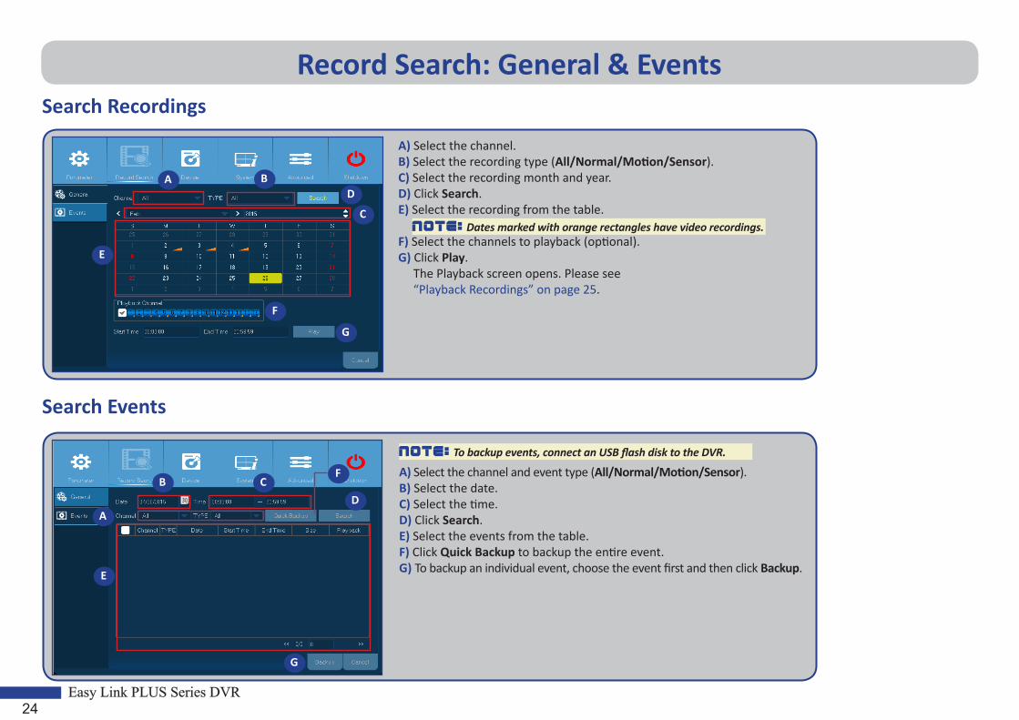
Record Search: General & EventsSearch Recordings
A) Select the channel.B) Select the recording type (All/Normal/Motion/Sensor).C) Select the recording month and year.D) Click Search.E) Select the recording from the table.
F) Select the channels to playback (optional).G) Click Play. The Playback screen opens. Please see “Playback Recordings” on page 25.
NOTE: Dates marked with orange rectangles have video recordings.
A BD
C
E
F
G
Search Events
NOTE: To backup events, connect an USB flash disk to the DVR.
A) Select the channel and event type (All/Normal/Motion/Sensor).B) Select the date.C) Select the time.D) Click Search.E) Select the events from the table.F) Click Quick Backup to backup the entire event.G) To backup an individual event, choose the event first and then click Backup.
A
B
D
C
E
F
G

Easy Link PLUS Series DVR25
Playback Recordings
a) Close - Click to close the Playback screen.b) Recording(s) - Video recordings from selected channels.c) Trim Video - Please see more in “Trimming Videos” on page 27.d) Volume Control - Slide the sliderbar to increase or decrease volume. Click to mute audio.e) Zoom In - Click to zoom in.f) Time Bar - The color indicates the video recording type: Normal recording (green), Motion recording (yellow), and Sensor recording (red).g) Recording Type Indicator - Motion, Smart (please see “Smart Search” on page 26), Sensor, and Normal. h) Time Frame - Select Playback timeline.i) Search Screen - Click to start a new search.j) Channels - Check the channels to playback.k) Recording Calendar - Dates marked with orange triangles have video recordings.
Playback ScreenPlayback Status
Playback Control
c d
f
k
j
gh
i
a
b
eFull screen
Record Search: General (continued)

26Easy Link PLUS Series DVR
Record Search: General (continued)Smart Search
Use this function if you want to find motion of a specific area inside normal continuous recording.
1) Select a channel for playback.
2) Click .3) Use the cursor to mark the area you want to find motion. It can be a certain area or the whole screen.
4) Click . As a result of the Smart Search, you will see motion recordings as
areas marked with dark green color inside the normal recording (green color).
Part of the Screen
Full Screen

Easy Link PLUS Series DVR27
Record Search: General (continued)Trimming Videos
Use this function if you need to backup just a certain section of the video recording.
1) Connect a USB flash drive to the DVR.2) Double-click on the channel (to display in full screen during video playback) that you wish to backup.3) Click on the Time Bar to mark the beginning of the video footage you wish to backup.4) Click .
4) Click on the Time Bar to mark the end of the video footage you wish to backup.5) Click .
The marked up area is now displayed within the red arrows.
A video type selection message appears.
Backup Type
H264
Channel: CH1Size: 890MBStart Time: 05:48:22End Time: 15:54:48
AVI
Save Cancel
6) Choose the video backup type and click Save.
NOTE: The device’s native video type is H.264. To view recordings in this format, please install the media player from the supplied product CD. AVI type is supported by most media players.

28Easy Link PLUS Series DVR
Device: HDD & PTZConfigure here the internal HDD that the DVR uses for saving the recordings. You need to format the HDD only at the first startup and if you replace the HDD.
• Format HDD: Select the HDD you want to format and then click Format HDD. To start formatting, you need to enter your user name and password and then click OK to confirm to continue formatting.
• Overwrite: Use this option to overwrite the old recordings on the HDD when the HDD is full. For example, if you choose the option 7 days then only the last 7 days recordings are kept on the HDD. To prevent overwriting any old recordings, select Disable. If you have disabled this function, please check the HDD status regularly, to make sure the HDD is not full.
This menu is for configuring the PTZ (Pan-Tilt-Zoom) settings for the dome camera. This feature is not supported.
• Channel: Choose a channel where is connected a dome camera.
• Protocol: Choose the communication protocol between the PTZ capable camera and DVR.
• Baudrate: The speed of the information sent from the DVR to the PTZ-capable camera. Make sure it matches the compatibility level of your PTZ-capable camera.
• DataBit/StopBit: The information between the DVR and PTZ-capable camera is sent in individual packages. The DataBit indicates the number of bits sent, while the EndBit indicates the end of the package and the beginning of the next (information) package. The available parameters for DataBit are the following: 8, 7, 6, 5. The available parameters for the StopBit are 1 or 2.
• Cruise: Enable to allow to use the Cruise mode. In order to use the Cruise mode, you need to set a number of preset points.
• Parity: Is necessary for error check. See the documentation of your PTZ-capable camera, to configure this setting.
• Address: Set the command address of the PTZ system. Please be noted that each PTZ-capable camera needs a unique address to function properly.

Easy Link PLUS Series DVR29
System: General & UsersIn this menu, you can configure the general parameters of the system, such as date and time, OSD language, menu timeouts, etc.
• Date/Time: Enter the date and time manually.
NOTE: For date/time automation over the Internet, enable NTP.
• Date Format: Set the date format here. For example, if you keep the default MM/DD/YY and today’s date is November 19th, 2013, the date appears on the footages as 11/19/2013.
• Time Format: Set the time format here. For example, if you keep the default 24Hour and the current time is 5:29:54 PM, the time appears on the footages as 17:29:54.
• Language: Choose the OSD language.
• Video Format: Choose the video format between NTSC and PAL. If the DVR’s picture is flickering or has only black screen, it may be that the video format is not correct.
• Menu Timeouts: Set the time out the DVR will exit the menus when they are not in use.
• Support Overscan: Check to allow adjusting the position of the video image on the live viewing screen.
• Show Wizard: Check if you want the Startup Wizard to reappear each time you startup the DVR.
Here you can configure the user login information.
NOTE: The default user name is “admin” and default password is “123456”.
• User Edit: To enable/disable the user account, modify the user name and password, click on the user account you wish to edit, then click Edit.
• Change User Permissions: To modify user access permissions, click on the user account you wish to modify, then click Permission.

30Easy Link PLUS Series DVR
System: DST & NTPDST stands for Daylight Savings Time.
• DST: Enable if Daylight Saving Time (DST) is observed in your country.
• Time Offset: Select the amount of time to offset for DST.
• Daylight Saving Time: - Start Time: Enter the Start Time by selecting the month, week, day, and time. - End Time: Enter the End Time by selecting the month, week, day, and time.
Stands for Network Time Protocol. This feature allows you to synchronize the date and time automatically on the DVR over Internet. Therefore the DVR needs to be connected to the Internet.
• NTP: Enable if you want the DVR to update the date and time automatically.
• Server Address: Select the NTP (Network Time Protocol) server.
• Time Zone: Select the Time Zone in your location.
• Update Now: Click here to update the system date and time.

Easy Link PLUS Series DVR31
System: Info & LogIn this menu you can view various system related information.
• Device Name: Enter the desired name for your DVR. The name can include both letters and numbers.
• Device ID: Enter the desired ID for your DVR. The device ID is used to identify the DVR, and can only be composed of numbers, and cannot be the same with other IDs when multiple DVRs are connected in the same network.
• MAC Address: Displays the MAC address of the DVR. When multiple DVRs are connected to the same network, each DVR must have a unique MAC address to ensure that the DVR can connect to the network.
The Log menu displays a list of events, presented in chronological order.
• To search for a log, enter the start time/end time to the respective fields and click Search.
• To display log details, double-click on the item.
• To backup a log, connect an external USB disk to the DVR, click on the log event and click Backup.
• Log Type: Select the log type.
• Start Time/End Time: Specify the start and end date/time of the logs you want to review and/or save on an external USB storage device. Click Search. The logs will be listed on the table.

32Easy Link PLUS Series DVR
Advanced: MaintainThe Maintain page allows you to set automatic system maintenance, load factory defaults, update the firmware settings.
• Load Default: Use this feature to restore the factory default settings of the DVR. It is recommended to load defaults for all options, after upgrading the firmware.
• Default User: If you want to log in to the DVR automatically for live view after each startup, then only administrator user account can be set for auto login.
• Auto Reboot: Set enable to reboot the DVR based on a schedule.
• Reboot: Choose to reboot the DVR on daily basis, on weekly basis, or on monthly basis.
• Update: Click to start updating the firmware.
• Load Settings: Select this option to import the settings that you have saved earlier, using the Save Settings function.
• Save Settings: Select this option to save the DVR current settings such as the video recording settings, network configurations, and etc to the USB device.

Easy Link PLUS Series DVR33
Advanced: Events & Auto UpgradeIn this menu you can set the type of events when you want the DVR to issue an alarm.
• Event Type: Select the event type. Options are: - Disk Full: When HDD is full. - Disk Error: If HDD is not detected properly. - Video Loss: If camera is not detected properly.• Enable: Click to enable the monitoring of the event.
• Show Message: Check the box to display a message on the screen when Disk Full, Disk Error, or Video Loss event happens.
• Send Email: Let the DVR to send you an auto-e-mail when an event occurs. To set up the e-mail and schedule, please see “Network: Email & Email Schedule” on page 18.
• Buzzer: Set the buzzer duration when the event occurs (Off/10 S/20 S/40 S/60 S). To disable buzzer, select Off.
The Auto Upgrade page allows you to set the DVR to look for system updates automatically.
• Auto Upgrade: Enable to allow to use on-line system upgrade.
• Check For updates: Check the checkbox to let the DVR look for updates.
• Detect: Click to look for updates.
• Upgrade: Click to upgrade the system over Internet directly.

34Easy Link PLUS Series DVR
Remote Access via Web ClientUse the Web Client to remotely access your DVR at anytime via a PC. Before you access the Web Client, you need to ensure that the network settings of the DVR are configured properly. The most convenient and easiest way is if you have set the DVR a static IP address (please see “Network: Network” on page 16). It means you only need to open the web browser on your PC and type in the static IP address you have set on the DVR. However, if the IP address of the DVR is assigned by a DHCP server (see “Network: Network” on page 16), then it means that each time you reboot the DVR, the IP address changes. In this case, ask if your ISP can provide you a static IP address. If not, then configure the DDNS service. See the network settings in “Network: Network” on page 16 and “Network: DDNS & FTP” on page 19. Also, please make sure the UPnP is configured in the DVR and router, or the manual port forwarding is completed in the router.
Logging In
To access the Web Client, do the following:
1) Launch the web browser (Internet Explorer) on your PC and enter the DVR static IP address or DDNS domain name (Host Name) you have set on DVR in the URL box.NOTE: The following IP address is an example only.
The user login page opens as shown.
2) Enter the User Name and Password.3) Click Login.
The default DVR user name is “admin” and default password is “123456”.

Easy Link PLUS Series DVR35
Remote Access via Web Client (continued)Remote Live Viewing Screen
This is the first screen that opens after you have logged in to the Web Client. Here you can show or disable channels ( ), start recording ( ) manually, take snapshots ( ) of the screens, configure PTZ settings (not supported), etc.
You can look for recorded files stored on the HDD inside the DVR, and save the result to the local directory on your PC. To configure the local directory. Please see “Local Settings Menu” listed below.
• Record Path: Set the path to save manual recordings on your PC’s local drive.• Download Path: Set the path on your PC’s local drive where you want to download
recordings from the DVR.• Snapshot Path: Set the path to save manual snapshots on your PC’s local drive.• Save: Click Save to save the modificaitons.• File Type: Choose your preferred file type for manual recordings.
Remote Playback Screen
Remote Settings Menu Local Settings Menu
Here you can remotely configure the settings of the DVR. Please see “Main Menu” on page 10 for more information.

36Easy Link PLUS Series DVR
TroubleshootingIf you experience any problems in using the DVR, try the following solutions to these common problems before calling for service. If problems persist, contact the customer service in your area.
Question: The DVR does not turn on and the indicators are not lit.
Answer: • Check if the power adapter (12V/2A) is properly connected.• Plug the power adapter to another power outlet, the current outlet may be damaged.• The power adapter may be damaged, contact the dealer to purchase a new one.
Question: Channels have no video signal. Answer: • Check if the cameras are properly connected.• Check if the cameras are supplied with power.• Set the correct video format used in your country (NTSC/PAL). See “System: General & Users” on page 29.• Check if the DVR is connected to KGUARD 720P Megapixel Cameras of PLUS Series (for example, model
number WA713APK or DA713FPK).
Question: The included extension cables (18M) are not long enough.
Answer: • To run longer distance, purchase the standard BNC cables (such as RG59 with pre-installed BNC connectors
on each end) in the length you need. Or contact local KGUARD distributors for more information.
Question: I have changed the administrator password but I cannot remember it.
Answer: • To obtain the factory default password, contact your retailer or directly send an email to KGUARD at
Question: The remote control is not working. Answer: • Make sure nothing is blocking the remote control and the DVR. Aim the remote control at a proper
distance.• Check the remote control batteries.
Question: I am getting too many email alerts. Answer: • Check the Sending Interval setting for the email alerts. See “Network: Email & Email Schedule” on page 18.• If the DVR keep reporting errors such as Video Loss or HDD error, check if the camera is properly connected
or other hardware configurations.
Question: I cannot access the web client. Answer: • Check if the network cable is properly connected to the DVR.• Check if the UPnP function is enabled in router and DVR or if the router does not support UPnP, then make
sure the port forwarding is completed.• Check if the network settings are properly configured. See “Network: Network” on page 16.• Ensure that you have Internet Explorer 6 or above.
Question: The buzzer keeps on sounding. Answer: • Check the Motion or Events settings. Motion Detection or Video Loss may be detected. Check the HDD
capacity and the video connections, which may be triggering the buzzer.

Copyright © 2015 All rights reserved
KGUARD INFORMATION CO., LTD. Address: 4F, No.113, Jian 2nd Road,
Jhonghe District, New Taipei City 23585, TaiwanTEL: +886-2-8228-6080 FAX: +886-2-8221-6857
Email: [email protected]
USA Technical Support ContactTEL:1-866-978-4888
Email: [email protected]
Customer Support