en suite living/dining/kitchen - plansandplanning.co.uk · all pre-stressed concrete lintels to be...
TRANSCRIPT

L0 Ground FFEExisting
0
Prop 1st Floor FCE
5226
Parapet
5815
1st Floor Proposed
2826Ground FCE Proposed
2600
2.6
02
.40
6.2 1st Floor
Roof - EDPM Flat - WARM
3.3 Parapet Gutter
2.1 Timber Framed Walls5.1 Stud Partitions
Floor - New Ground
3.1 Roof over ground flooraccommodation
7.3 External Stairs
7.2 Balustrades
Walls - Foundations
Walls - Rendered
Custom Rooflights to manufacturers specification
76 m²Living/Dining/Kitchen
12 m²En Suite
6 m²Dress 1
UB254x146x37
UB152x89x16
UB203x102x23
Or as specified by specialist supplier thesatisfaction of the building inspector.
Specialist design ot wall and parapetto satisfaction of the buildinginspector and to achieve all to givemin U Value of .28 W/M2K.and AA fire rating
Detail design by specialistto the satisfaction of thebuilding inspector
Render to be replaced by specialistCladding installed to manufacturersinstructions and to achieve min AAfire rating
Asbuilt Drawings - as this is a drawing of an existing building there will be variations on site to wall thicknesses and angles that are not depicted in this drawing.Unless stated inaccessible areas such as roofs have been visualy observed.Unless otherwise stated this is not a topograghic survey and ground levels and features have been estimated.This drawing is the property of Plans and Planning and should not be reproduced without written permission.Contractors are to check all dimensions and levels prior to site works commencementUnless stated specifically this drawing has not been plan checked by Building Control and the notes are for general guidance only.If there are no structural calculations accompanying this drawing then sizes of structural components are approximate and should be checked by the builder.
Client
Site
Petworth Lodge1a Hillbrook RdBramhallStockport SK7 2BT
Project
Job No
plansandplanning
www.plansandplanning.co.uk
Drawing Date
Print to Scale on A1
Email - [email protected] Tel - 07770 820611
Drawing
Date Revision
Status
26/02/2015 08:06:37
26/02/2015 08:06:37
Raj Kalia
7 Sandiway Drive,
Didsbury,
Manchester M20 2FE
Building Regs
Bungalow Extend and ReModel
Sections and Notes BRegs 100
2014-40
Construction Notes Based on Leapfrog Specification and Engineers Notes
Key Value Keynote Text
1 GENERAL NOTES FIRE ALARMS - Smoke and heat detectors to be installed in accordance with BS 5839: Pt.6 - Minimum System D to Grade LD3. Heat alarm in kitchen with smoke alarms in hallways and landing areas. Mains powered Interlinked alarms with back up power supply. Once installed andcommissioned all certificates and instructions for maintenance and use of the system are to be given to the householder.FIRE PROTECTION - Any existing steel beams exposed following site strip out supporting elements of structure are to be wire brushed & intumescent painted, all steel beams to be cased in on all sides with one layer of 12.5mm or15mm British Gypsum Fireline board on GyprocGypliner framing as necessary finished with 5mm gypsum two coat plaster skim to achieve one hour fire resistance.BATHS - All Baths to be provided with a temperature mixing value to the bath, to prevent the temperature of delivered water not exceeding 48°CFIRE SPREAD - Ensure all new/replacement linings meet National Class 1FIRE ESCAPE - New habitable rooms at first floor level to have minimum unobstructed opening of 0.33m2 and at least 450mm high and 450mm wide. The bottom of the opening area to be 1100mm maximum and 800mm minimum above finished floor level.THERMAL BRIDGING - All openings closed at jambs and sills with proprietary closers or block work of suitable depth to give minimum 0.45m2 K/W.LINTELS - insulated and to have base plate perforated. Cavity insulation to be taken up to underside of roof insulation. Door/window frames to overlap proprietary/block work closer by 30mm. All joinery weather stripped. All junctions of joinery and masonry and plaster/render tohave sealant joint.FACIAS & GUTTERS - Fascias, soffit's and barge boards to match and line through with existing. Install PVC gutter 125 half round to eaves and 75mm down pipes, securely fixed back to roof and external walls to give overhang to roof as shown on design details. ensure breathablemembrane turns into gutter from main roof in accordance with manufacturers instructions.GUTTERS/RWP - Rainwater fittings to match existing. Allow for rodding access at base of rainwater pipes.LEADWORK - All lead work to be to Lead Association GuidelinesELECTRICS - Electrical services shall be designed and installed in accordance with the latest amendments of the NICEIC and IEE regulations and installed in accordance with Part P of the Building Regulations for the safety of electrical installations for buildings. See wiringregulations (BS 7671)SWITCHES & SOCKETS - To be wpositioned between 450mm and 1200mm above the floor level.ENERGY - At least 75 of lighting to be energy efficient in accordance with the DOMESTIC SERVICES COMPLIANCE GUIDE 2010HEATERS - and thermostatic controls to radiators and other heater types to be in accordance with the DOMESTIC SERVICES COMPLIANCE GUIDE 2010GAS APPLIANCES - Installed and tested by Gas Safe Registered plumberGLAZING -All glazing located with 800mm above the finished floor level in internal and external walls and partitions. Within 1500mm above the finished floor level in a door or adjacent side panel, should be safety glass in accordance with BS 6206.DOORS - All new doors to have a U Value of 1.8 w/m2k or lowerWINDOWS - All new windows to have a U Value of 1.6 w/m2k or lower minimum Double glazed units, with min 16mm Argon gas filled or 20 mm air gap and low 'e' soft coated inner pane - or as specified in any Heat Loss Calculation suppliedSKIRTINGS & ARCHITRAVES - generally to match existing unless specified by clientCOVING - To match existing unless specified by clientLINTELS - For uniformly distributed loads and standard 2 storey domestic loadings onlyLintel widths are to be equal to wall thickness. All lintels over 750mm sized internal door openings to be 65mm deep pre-stressed concrete plank lintels. 150mm deep lintels are to be used for 900mm sized internal door openings. Lintels to have a minimum bearing of 150mm on eachend. All pre-stressed concrete lintels to be designed and manufactured in accordance with BS 8110, with a concrete strength of 50 or 40 N/mm² and incorporating steel strands to BS 5896 to support loadings assessed to BS 5977 Part 1.For other structural openings provide proprietary insulated steel lintels suitable for spans and loadings in compliance with Approved Document A and lintel manufacture standard tables. Stop ends, DPC trays and weep holes to be provided above all externally located lintels.SVP - Ventilation pipe to terminate min. 300mm above where it penetrates through the finished roof level or if within 3.0m of a window then 900mm above window head. - Pipes which pass through the roof finish to be dressed with roof flashing and to terminate in proprietary ventfitted with durable wire cage or other cover which does not restrict the flow of air.RODDING - SVP to have removable Rodding access at base of SVP to allow for Rodding.INTERNAL SVP - SVP's to be boxed in with 50 x 50mm stud work with plywood finish, with removable panel to allow for access to SVP.WASTE - 100mm waste from WC.40mm waste from WHB with 75mm deep seal trap.50mm waste from shower with 75mm deep seal trap.ALL PROPOSED brickwork/blockwork to be tied into existing walls where they abut using tooth bonding. Cavities are to be made continuous.SAFETY GLASS - Where cill Ht is below 800mm use toghened glass to BS 6399 Pt1 and fit adult overidable opener restrictor (100mm)
All schedules of windows and doors and room sizes are for general assistance and should all be verified by the builder. They should not be used for ordering or relied on for cost estimates.
2.0 External Walls External masonry walls to have their thermal performance upgraded by the addition of 70mm rigid external wall insulation below the render in accordance with document L1B of Building Regulations 2010 http://www.planningportal.gov.uk/uploads/br/BR_PDF_AD_L1B_2011.pdf
2.1 Timber Framed Walls 150mm thk. treated SW stud frame with 15mm OSB/ply sheathing to outer face. Studs filled with 140mm thk. Kingspan Kooltherm K12 or similar and 12.5mm gypsum plasterboard internally with 5mm skim finish. External face clad in breather membrane back to sheathing boardwith 70mm Kingspan EWB or similar direct fixed and mounted on Wemico system profiles then variously rendered in K Rend or similar thin coat silicone render system in white or clad with cedar cladding on treated SW battens.
3.1 Roof over ground flooraccommodation
Warm roof of Dark Grey GRP 3 coat system with Gel coat according to British Standards to BS476 part 3 FAB fully adhered to 100mm Kingspan or similar with tubular fixings through water membrane (vapour barrier) on 18mm structural OSB ply deck fixed on firrings to achievedrainage falls on treated SW timber rafters to Structural Engineer’s specification. Joists filled with mineral wool insulation maintaining 50mm air gap to u/side deck with plasterboard or similar + plaster skim to underside.
3.3 Parapet Gutter Dark Grey GRP 3 coat system with Gel coat according to British Standards to BS476 part 3 FAB fully adhered to 18mm structural WBP ply deck fixed on firrings to acheive falls on treated SW timber joists to S.E specification
5.1 Stud Partitions 100x50mm timber studding with unfaced mineral wool batts or quilt (min. thickness 25mm, min. density 10kg/m3) between studs with 12.5mm plasterboard + plaster skim to both room faces.
6.2 1st Floor 18mm MRMFC or OSB t&g flooring fully glued and screwed on SW timber joists to Structural Engineer’s specification
7.1 Internal Stairs Preformed SW staircase approximately 2.2m wide overall with square nose and cut string
7.2 Balustrades 15mm toughened glass panels in set in steel clamps to PiIlkington standard details. Steel clamps to be concealed by plasterboard and skim linings. Where building control will allow, there will be no or minimal handrails
7.3 External Stairs Galvanised steel spiral stair to lead from the ground floor terrace to the master bedroom external deck. Details to be confirmed.
CATNIC CG70/100 All Window Heads to be supported underneath by Catnic (or othersimilar) LintelsAlso DPC slip planes over as per Manufacturers instructions
CHECKS TO EXISTINGSTRUCTURE
EXISTING STRUCTUREExisting structure including foundations, beams, walls and lintels carrying new and altered loads are to be exposed and checked for adequacy prior to commencement of work and as required by the Building Control Officer.
Drainage - New ABOVE GROUND DRAINAGEAll new above ground drainage and plumbing to comply with BS.5572.1978 for sanitary pipework. All drainage to be in accordance with Part H of the Building Regulations. Wastes to have 75mm deep anti vac bottle traps and rodding eyes to be provided at changes of direction.
Size of wastes pipes and max length of branch connections (if max length is exceeded then anti vacuum traps to be used)Wash basin - 1.7m for 32mm pipe 4m for 40mm pipeBath/shower - 3m for 40mm pipe 4m for 50mm pipeW/c - 6m for 100mm pipe for single WCAll branch pipes to connect to 110mm soil and vent pipe terminating min 900mm above any openings within 3m.Or to 110mm upvc soil pipe with accessible internal air admittance valve complying with BS EN 12380, placed at a height so that the outlet is above the trap of the highest fitting.Waste pipes not to connect on to SVP within 200mm of the WC connection.Supply hot and cold water to all fittings as appropriate.
Drains - Existing Existing Drain positions are approximate - no survey has been carried out.New Services are to connect to existing to the satisfaction of the Building Inspector.Any services terminated must be removed or blocked.All new drains must be roddable and have a minimum fall of at least a 18mm fall in for every metre of pipe run - min diameter 110mmUNDERGROUND FOUL DRAINAGEUnderground drainage to consist of 100mm diameter UPVC proprietary pipe work to give a 1:40 fall. Surround pipes in 100mm pea shingle. Provide 600mm suitable cover (900mm under drives). Shallow pipes to be covered with 100mm reinforced concrete slab over compressiblematerial. Provide rodding access at all changes of direction and junctions. All below ground drainage to comply with BS7158 and BS801.
Floor - New Ground FLOORS - 22mm Moisture resistant t&g chipboardJOISTS - as specified - Double Joists under partitions. - All joists are to have ends treated with 3 coats of green cuprinol and are to be wrapped in DPC prior to fixing to joist hangers/ pfc to external and internal walls. - Fix 100 x 50mm cross noggins to stiffen unsupported endsof t&g at perimeter, middle of room and at board joints.MINIMUM 150mm gap between over site and bottom of joistsINSULATION - 100mm Kingspan TF70 (or equivalent) between the joists to achieve Min U Value of .22 - Fit Noggins to support InsulationVENTILATION - Floor void ventilated as noted with proprietary ventilators at approx 1800 crs fixed in full accordance with manufacturers recommendations - Ensure ventilation is maintained to existing floorOVERSITE - Min 100mm over site with min 150mm to underside of the Joist
Roof - EDPM Flat - WARM WARM FLAT ROOF(imposed load max 1.0 kN/m² - dead load max 0.75 kN/m²)To achieve U value of 0.18 W/m²KFlat roof to be single ply membrane roofing providing aa fire rating for surface spread of flame with a current BBA or WIMLAS Certificate and laid to specialist specification. Single ply membrane to be fixed to 22mm exterior quality plywood over 120mm Kingspan ThermaroofTR27 /FM LPC.Insulation bonded to 22mm external quality plywood decking or similar approved on sw firings to minimum 1 in 80 fall on sw treated 47 x 220mm C24 flat roof joists at 400mm ctrs to give a max span of 5.08m or as Structural Engineer's details and calculations. Underside of joiststo have 12.5mm foil backed plasterboard and skim. Provide cavity tray to existing house where new roof abuts existing house.Provide restraint to flat roof by fixing of 30 x 5 x 1000mm ms galvanised lateral restraint straps at maximum 2000mm centres fixed to 100 x 50mm wall plates and anchored to wall.THIS IS A GENERAL GUIDE BASED ON NORMAL LOADING CONDITIONS FOUND IN DOMESTIC CONSTRUCTION. IT IS YOUR RESPONSIBILITY TO ASSESS YOUR DESIGN TO ASCERTAIN WHETHER ENGINEER'S DETAILS/CALCULATIONS ARE REQUIRED.PLEASE REFER TO THE TRADA DOCUMENT – 'SPAN TABLES FOR SOLID TIMBER MEMBERS IN FLOORS, CEILINGS AND ROOFS FOR DWELLINGS' OR ASK YOUR BUILDING CONTROL OFFICER FOR ADVICE.
RWP New Rain Water Pipe - Connect to main drains - ensure all are roddable - New rainwater goods to be new 110mm UPVC half round gutters taken and connected into 68mm dia UPVC downpipes.
Stairs - New New staircase to comply with Building Regs. Approved Document K1 and Approved Doc B Fire Safety - In particular;Maximum Rise = 220PITCH - not to exceed 42 degeesMinimum Going = 220Min Headroom = 2000 above pitch lineMinimum landing depth 400Handrails both sides at 900-1000mm from pitch lineMax Pitch 42 degreesGuarding such that a 100mm sheer cannot pass through guarding.
Ventilation - Bathrooms RAPID VENTILATION - MECHANICAL EXTRACT VENTILATION capable of extracting at a rate not less than 30 litres per second which may be operated intermittently and should also have rapid ventilation by means of a ventilation opening with a total area of at least 1/20th ofthe floor area of the room, with part of that opening at least 1.75m above the floor.NATURAL VENTILATION - To be provided by one or more ventilation openings with a total area of at least 1/20th of the floor area of the room, with part of that opening at least 1.75m above the finished floor level.BACKGROUND VENTILATION - To be provided by trickle ventilators positioned in the window head which should be controllable and secure having a total area not less that 4000 square millimetres. Maintain min. 10mm air gap beneath doors.DOORS - All new doors to have trickle vents - 10000mm2INNER ROOMS WITHOUT WINDOWS - Ensure 15min extract overrun to WC's and Bathrooms
Ventilation - General NATURAL VENTILATION - To be provided by one or more ventilation openings with a total area of at least 1/20th of the floor area of the room, with part of that opening at least 1.75m above the finished floor level.BACKGROUND VENTILATION - To be provided by trickle ventilators positioned in the window head which should be controllable and secure having a total area not less that 8000 square millimetres. Maintain min. 10mm air gap beneath doors.DOORS - All new doors to have trickle vents - 10000mm2
Ventilation - Kitchens &Utility
RAPID VENTILATION - To be provided by means of an extract fan capable of extracting at a rate not less than 60 litres per second, or cooker hood capable of extracting a rate of 30 litres per second direct to the external air.NATURAL VENTILATION - To be provided by one or more ventilation openings with a total area of at least 1/20th of the floor area of the room, with part of that opening at least 1.75m above the finished floor level.BACKGROUND VENTILATION - To be provided by trickle ventilators positioned in the window head which should be controllable and secure having a total area not less that 2500 square millimetres. Maintain min. 10mm air gap beneath doors. MECHANICAL VENTILATION inUtility of a minimum 30 litre per secondDOORS - All new doors to have trickle vents - 10000mm2
Walls - Brick OUTER LEAF - 102.5mm facing brickwork to match existingCAVITY - 105mm Cavity - Insulation using 50mm Kingspan K8 Cavity Board installed to manufacturers instructions with residual cavity of 50mm all to give min U Value of .28 W/M2K. Anderson waterproofing Xtra load elite pitch free polymeric DPC min 150mm above ground level.Insulated vertical damp proof course to jambs at all openings in external walls.INNER LEAF - 100mm block work inner leaf Thermalite Hi-Strength 7 - designed thermal conductivity 0.19W/mK, Compressive strength 7N/mm2 & a nominal density 730kg/m3WALL TIES - Stainless steel wall ties to relevant BS 1243:1978/81 - 6no per m2 Vertical twist type,max.450mm centers vertically in staggered rows and 750mm centers horizontally; extra ties at reveals max 300mm vertical crs & to each block course to sides of openings (within225mm) all to BS 5628:part 3: 1985CAVITY CLOSERS - Cavities closed at eaves, verges and openings with proprietary insulated cavity closer's as described. - Cavity closer's to be type H cavicloser universal cavity closer DPC by "cavity trays of Yeovil" or similar approved to be at reveals & jambs to providethermal insulation or to be made with block work to seal cavities but still to provide thermal break.CAVITY TRAYS - Bed cavity trays on mortar as work proceeds observe usual codes of practice and standards. incorporate weep vents as required eg.minimum of 2 per cavity tray length. Provide cavity wall weep, to provide an outlet drain to discharge water from tray. Alsoventilator as required to ventilate wall cavities.LINTELS - All new Lintels to be fully insulated proprietary Galvanized pressed steel to BS 5977: 1983 in External Cavity with half hour fire resistance , min 150mm end bearings & built into specification, inc preformed cavity trays & stop ends provided over openings in externalwalls. Profile & gauge of lintels to be in accordance with the manufacturers recommendations & to the Structural Engineers approval. - All new Lintels, steel beams and structural timbers to be in accordance with the Structural Engineers design & schedules including new concretepadstones as specified.WALLS LONGER THAN 12M - to have vertical expansion joints at 12m intervals sealed with proprietary flexible sealant to manufacturers instructions.
Walls - Foundations DEPTH -Min 900mm below ground - 600mm*300mm or as in engineeres notes. If there are any drains within 1000mm of the foundations then foundations to be lower than drains WALLS BELOW GROUND - All new walls to have Class A blockwork below ground level or alternatively semi engineering brickwork in 1:4 masonry cement or equal approved specification. Cavities below ground level to be filled with lean mix concrete min 225mm below damp proofcourse. Or provide lean mix backfill at base of cavity wall (150mm below damp course) laid to fall to weepholes.CAVITY - Weak mix 1:3:6 concrete cavity infill below ground levelWALL TIES- Stainless steel wall ties to relevant BS 1243:1978/81 - 6no per m2 Vertical twist type,max.450mm centers vertically in staggered rows and 750mm centers horizontally; extra ties at reveals max 300mm vertical crs & to each block course to sides of openings (within225mm) all to BS 5628:part 3: 1985DPC - Minimum 150mm above ground level
Walls - Rendered OUTER LEAF - 100mm block work inner leaf Thermalite Hi-Strength 7 - designed thermal conductivity 0.19W/mK, Compressive strength 7N/mm2 & a nominal density 730kg/m3 - RENDERED - and painted to satisfaction of planning department.CAVITY - 105mm Cavity - Insulation using 50mm Kingspan K8 Cavity Board installed to manufacturers instructions with residual cavity of 25mm all to give min U Value of .28 W/M2K.. Anderson waterproofing Xtra load elite pitch free polymeric DPC min 150mm above ground level.Insulated vertical damp proof course to jambs at all openings in external walls.INNER LEAF - 100mm block work inner leaf Thermalite Hi-Strength 7 - designed thermal conductivity 0.19W/mK, Compressive strength 7N/mm2 & a nominal density 730kg/m3WALL TIES - Stainless steel wall ties to relevant BS 1243:1978/81 - 6no per m2 Vertical twist type,max.450mm centers vertically in staggered rows and 750mm centers horizontally; extra ties at reveals max 300mm vertical crs & to each block course to sides of openings(within225mm) all to BS 5628:part 3: 1985CAVITY CLOSERS - Cavities closed at eaves, verges and openings with proprietary insulated cavity closer's as described. - Cavity closer's to be type H cavicloser universal cavity closer DPC by "cavity trays of Yeovil" or similar approved to be at reveals & jambs to providethermal insulation or to be made with block work to seal cavities but still to provide thermal break.CAVITY TRAYS - Bed cavity trays on mortar as work proceeds observe usual codes of practice and standards. incorporate weep vents as required eg.minimum of 2 per cavity tray length. Provide cavity wall weep, to provide an outlet drain to discharge water from tray. Alsoventilator as required to ventilate wall cavities.LINTELS - All new Lintels to be fully insulated proprietary Galvanized pressed steel to BS 5977: 1983 in External Cavity with half hour fire resistance,min 150mm end bearings & built into specification, inc preformed cavity trays & stop ends provided over openings in externalwalls. Profile & gauge of lintels to be in accordance with the manufacturers recommendations & to the Structural Engineers approval. - All new Lintels, steel beams and structural timbers to be in accordance with the Structural Engineers design & schedules including new concretepadstones as specified.WALLS LONGER THAN 12M - to have vertical expansion joints at 12m intervals sealed with proprietary flexible sealant to manufacturers instructions.
1 : 50Cross Section 12
DoorSchedule - Sizes & styles illustrative - dimensions given are approx
Number Type Floor Width Height Fire Rating
01 Doors_ExtSgl_1 L0 Ground FFE Existing 1010 2110
02 Doors_Garage_Horz_Pnl L0 Ground FFE Existing 4278 2100
03 Doors_IntDbl_8 L0 Ground FFE Existing 1510 2110
04 Doors_Sgl_Glass_No_Frame_2 L0 Ground FFE Existing 1590 2562
05 Exterior Sliding Door L0 Ground FFE Existing 1825 2087
06 Exterior Sliding Door L0 Ground FFE Existing 1825 2087
07 Exterior Sliding Door L0 Ground FFE Existing 1825 2087
08 IntSgl Plain L0 Ground FFE Existing 830 1950
09 IntSgl Plain L0 Ground FFE Existing 830 1950
10 IntSgl Plain L0 Ground FFE Existing 830 1950
11 IntSgl Plain L0 Ground FFE Existing 830 1950
12 IntSgl Plain L0 Ground FFE Existing 830 1950
13 IntSgl Plain L0 Ground FFE Existing 830 1950
14 IntSgl Plain L0 Ground FFE Existing 830 1950
15 Sliding-Door L0 Ground FFE Existing 5840 2400
16 Doors_IntDbl_8 1st Floor Proposed 1510 2110
17 IntSgl Panel 1st Floor Proposed 834 1950 -
18 IntSgl Panel 1st Floor Proposed 834 1950 -
19 IntSgl Panel 1st Floor Proposed 834 1950 -
20 IntSgl Panel 1st Floor Proposed 834 1950 -
21 IntSgl Panel 1st Floor Proposed 834 1950 -
22 IntSgl Panel 1st Floor Proposed 834 1950 -
23 IntSgl Panel 1st Floor Proposed 834 1950 -
24 IntSgl Panel 1st Floor Proposed 834 1950 -
25 IntSgl Panel 1st Floor Proposed 834 1950 -
26 Sliding-Door 1st Floor Proposed 4400 2400
27 Sliding_Door_-_Adjustable 1st Floor Proposed 1524 2134
28 Sliding_Door_-_Adjustable 1st Floor Proposed 1524 2134
29 Sliding_Door_-_Adjustable 1st Floor Proposed 1524 2134
30 Sliding_Door_-_Adjustable 1st Floor Proposed 1524 2134
Window Schedule - Sizes & styles illustrative - dimensions given are approx
Number Floor Type Width Height Sill Height
01 L0 Ground FFE Existing Casement (2) 1750 1250 900
02 1st Floor Proposed Casement (2) 1800 1330 1165
03 1st Floor Proposed Casement (2) 1800 1330 1165
04 1st Floor Proposed Casement (2) 1300 500 1900
05 1st Floor Proposed Casement (2) 1167 500 1900
06 1st Floor Proposed Casement (2) 2500 500 1900
07 1st Floor Proposed Sgl Casement - Top Hung 1192 1021 1400
Sheet List
Sheet Number Sheet Issue Date Sheet Name
BRegs 100 08/27/14 Sections and Notes
BRegs 101 11/23/14 Plans and Elevations
BRegs 102 02/21/15 Structural Details
P100 03/05/14 Location
3d Structural1
All Structural details, Positions and connections to be as the engineers notes. All representationsin these drawings are illustrative.
D02
D04D01
01
0705 06
D01 D07
1.40
1.40
1.80
2.7
9
4.5m wide
D15D05 D06
D26
0203
D01
0704
BRegs101
4
BRegs101
2
BRegs101
1
BRegs101
3
BRegs101
6
BRegs101
8
BRegs101
5
BRegs101
7
2
BRegs 100
1.50
1.50 0.9
0
0.90
2.00
1.00
1.20
1.20
RWP
RWP
16 m²Bdrm 316 m²
Lndg
6 m²Bath
19 m²Bdrm 2
Roof Space
6 m²Dress 1
36 m²Bdrm 1
18 m²Bdrm 2
25 m²Lndg
9 m²Bath
19 m²Bdrm 3
19 m²Bdrm 4
Dn
2
BRegs 100
4.89
3.9
66
.32
12 m²En Suite
pproximate Position and style of spiral staircase
4.5
m w
ide
2 m²Robes
3 m²En Suite
1 m²Cpd
6.12 2.155.01
9.1
4
3.504.89
9.0
49
.14
3.03 2.53
0.611.30
1.64
1.80
1.03
1.80
0.6
31.
172
.68
2.5
0
0.531.19
2.0
31.
31
2.201.44
4.44
4.2
9
1.75
2.4
0
D17
D18
D19
D20 D21
D22
D27
D28
D29
D30
D23
D26
D24 D25
D16
02
03
07
04
05
06
27 m²Garage
5 m²Utility
1 m²Boiler
21 m²Kitchen
46 m²Lounge
13 m²Hall
1 m²Stairs
4 m²Cloaks
2 m²WC
14 m²Sitting Room 1
5 m²EnSte 1
3 m²Robes 1
23 m²Bdrm 1
12 m²Study
5 m²Rear Hall
27 m²Garage
10 m²Utility
1 m²Boiler
76 m²Living/Dining/Kitchen
21 m²Hall
2 m²Cloaks
21 m²Study
24 m²Lounge
4 m²Wc
2
BRegs 100
6.79
6.0
0
9.1
3
0.69
7.1 Internal StairsStairs - New
Ventilation - Bathrooms
Ventilation - Kitchens & Utility
Ventilation - General
Drains - ExistingDrainage - New
D08
D03 D09
D10
D11
D02
D12
D13
D15
D04
D01D05
D06
D07
D14
01
Asbuilt Drawings - as this is a drawing of an existing building there will be variations on site to wall thicknesses and angles that are not depicted in this drawing.Unless stated inaccessible areas such as roofs have been visualy observed.Unless otherwise stated this is not a topograghic survey and ground levels and features have been estimated.This drawing is the property of Plans and Planning and should not be reproduced without written permission.Contractors are to check all dimensions and levels prior to site works commencementUnless stated specifically this drawing has not been plan checked by Building Control and the notes are for general guidance only.If there are no structural calculations accompanying this drawing then sizes of structural components are approximate and should be checked by the builder.
Client
Site
Petworth Lodge1a Hillbrook RdBramhallStockport SK7 2BT
Project
Job No
plansandplanning
www.plansandplanning.co.uk
Drawing Date
Print to Scale on A1
Email - [email protected] Tel - 07770 820611
Drawing
Date Revision
Status
26/02/2015 08:06:44
26/02/2015 08:06:44
Raj Kalia
7 Sandiway Drive,
Didsbury,
Manchester M20 2FE
Building Regs
Bungalow Extend and ReModel
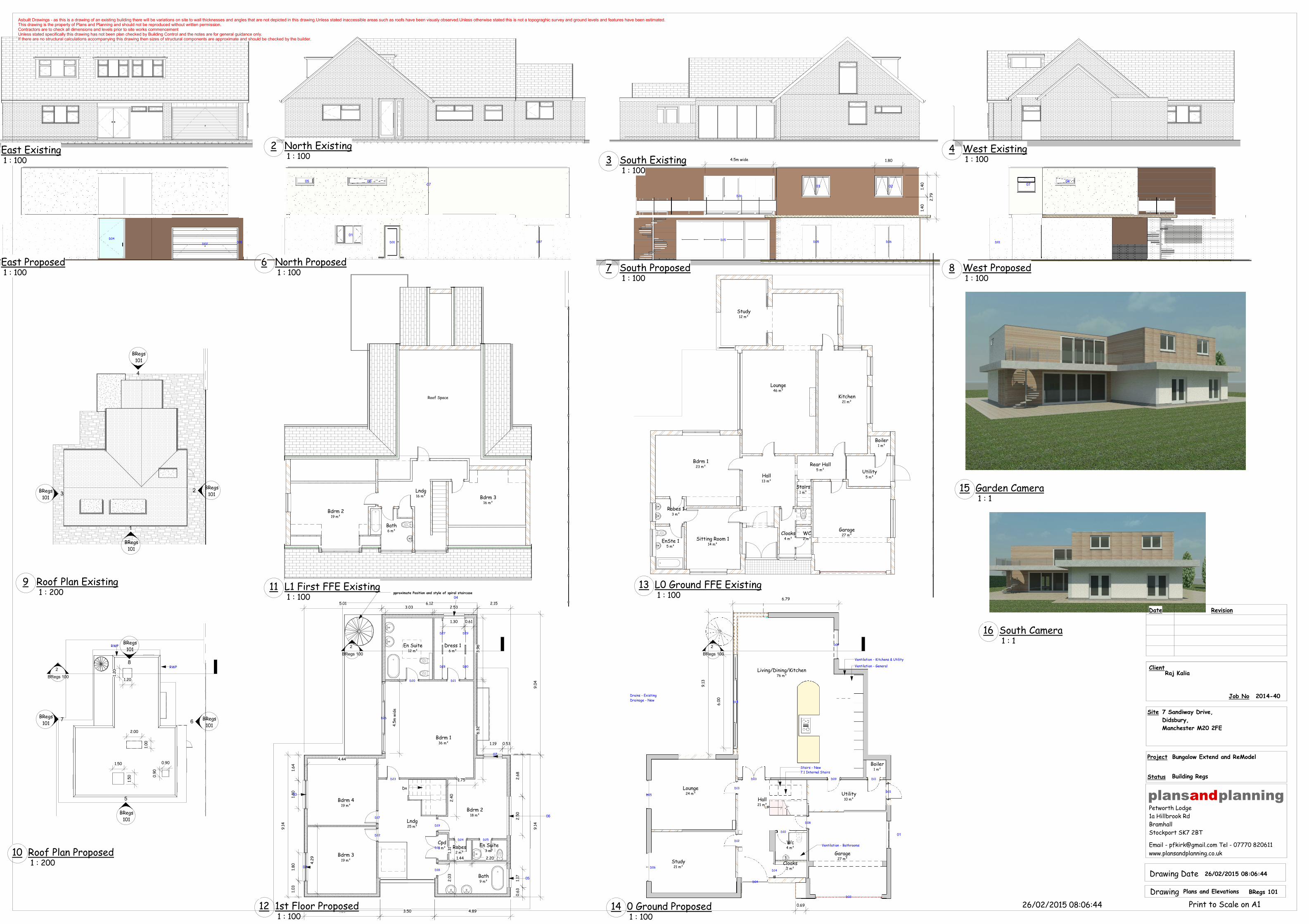
Plans and Elevations BRegs 101
2014-40
1 : 100East Existing
1 : 100North Existing2
1 : 100South Existing3 1 : 100
West Existing4
1 : 100East Proposed
1 : 100North Proposed6
1 : 100South Proposed7
1 : 100West Proposed8
1 : 200Roof Plan Existing9
1 : 200Roof Plan Proposed10
1 : 100L1 First FFE Existing11
1 : 1001st Floor Proposed12
1 : 100L0 Ground FFE Existing13
1 : 1000 Ground Proposed14
1 : 1Garden Camera15
1 : 1South Camera16

Asbuilt Drawings - as this is a drawing of an existing building there will be variations on site to wall thicknesses and angles that are not depicted in this drawing.Unless stated inaccessible areas such as roofs have been visualy observed.Unless otherwise stated this is not a topograghic survey and ground levels and features have been estimated.This drawing is the property of Plans and Planning and should not be reproduced without written permission.Contractors are to check all dimensions and levels prior to site works commencementUnless stated specifically this drawing has not been plan checked by Building Control and the notes are for general guidance only.If there are no structural calculations accompanying this drawing then sizes of structural components are approximate and should be checked by the builder.
Client
Site
Petworth Lodge1a Hillbrook RdBramhallStockport SK7 2BT
Project
Job No
plansandplanning
www.plansandplanning.co.uk
Drawing Date
Print to Scale on A1
Email - [email protected] Tel - 07770 820611
Drawing
Date Revision
Status
26/02/2015 08:06:45
26/02/2015 08:06:45
Raj Kalia
7 Sandiway Drive,
Didsbury,
Manchester M20 2FE
Building Regs
Bungalow Extend and ReModel
Structural Details BRegs 102
2014-40
Asbuilt Drawings - as this is a drawing of an existing building there will be variations on site to wall thicknesses and angles that are not depicted in this drawing.Unless stated inaccessible areas such as roofs have been visualy observed.Unless otherwise stated this is not a topograghic survey and ground levels and features have been estimated.This drawing is the property of Plans and Planning and should not be reproduced without written permission.Contractors are to check all dimensions and levels prior to site works commencementUnless stated specifically this drawing has not been plan checked by Building Control and the notes are for general guidance only.If there are no structural calculations accompanying this drawing then sizes of structural components are approximate and should be checked by the builder.
Client
Site
Petworth Lodge1a Hillbrook RdBramhallStockport SK7 2BT
Project
Job No
plansandplanning
www.plansandplanning.co.uk
Drawing Date
Print to Scale on A1
Email - [email protected] Tel - 07770 820611
Drawing
Date Revision
Status
26/02/2015 08:06:46
26/02/2015 08:06:46
Raj Kalia
7 Sandiway Drive,
Didsbury,
Manchester M20 2FE
Building Regs
Bungalow Extend and ReModel
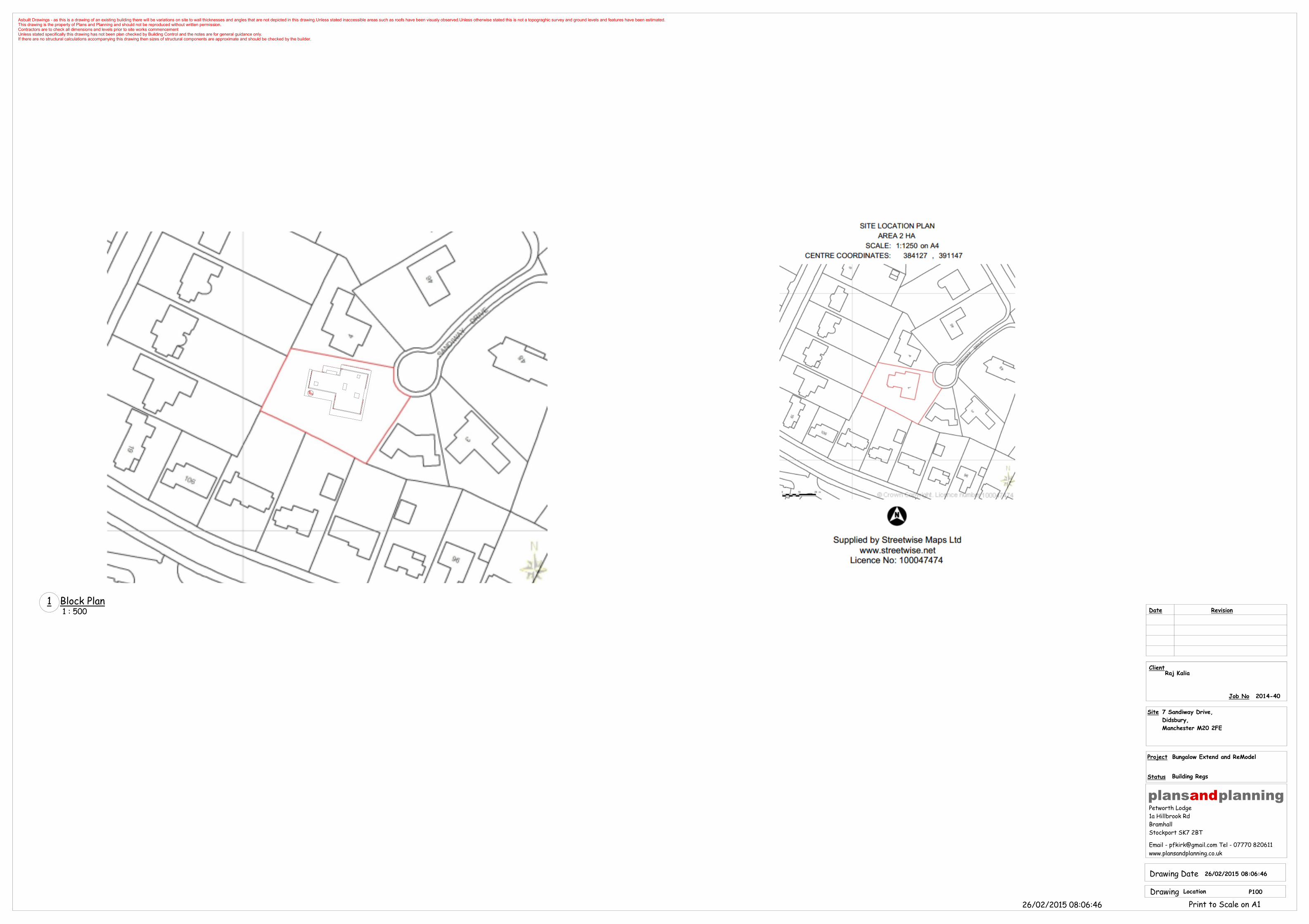
Location P100
2014-40
1 : 500Block Plan1