en metalwork measuring and testing for instructors
TRANSCRIPT

8/8/2019 En Metalwork Measuring and Testing for Instructors
http://slidepdf.com/reader/full/en-metalwork-measuring-and-testing-for-instructors 1/22
Measuring and Testing − Course: Technique for Manual Working ofMaterials. Methodical Guide for Instructors

8/8/2019 En Metalwork Measuring and Testing for Instructors
http://slidepdf.com/reader/full/en-metalwork-measuring-and-testing-for-instructors 2/22

8/8/2019 En Metalwork Measuring and Testing for Instructors
http://slidepdf.com/reader/full/en-metalwork-measuring-and-testing-for-instructors 3/22
Table of ContentsMeasuring and Testing − Course: Technique for Manual Working of Materials. Methodical Guide forInstructors.........................................................................................................................................................1
1. Objectives and contents of practical vocational training in the working techniques of "Measuringand Testing"...........................................................................................................................................12. Organizational preparation.................................................................................................................13. Recommendations for practical vocational training in the working techniques of "Measuring andTesting"..................................................................................................................................................3
4. Application of the working techniques of "Measuring and Testing"..................................................145. Captions and legends of the "Measuring and Testing" transparencies series..................................17
i

8/8/2019 En Metalwork Measuring and Testing for Instructors
http://slidepdf.com/reader/full/en-metalwork-measuring-and-testing-for-instructors 4/22
ii
8/8/2019 En Metalwork Measuring and Testing for Instructors
http://slidepdf.com/reader/full/en-metalwork-measuring-and-testing-for-instructors 5/22
Measuring and Testing − Course: Technique for Manual Working ofMaterials. Methodical Guide for Instructors
Institut für berufliche Entwicklung e.V.Berlin
Original title:Methodische Anleitung für den Lehrenden
"Messen und Prüfen"
Author: Frank Wenghöfer
First edition © IBE
Institut für berufliche Entwicklung e.V.Parkstraße 2313187 Berlin
Order No.: 90−32−3101/2
1. Objectives and contents of practical vocational training in the working techniquesof "Measuring and Testing"
By concluding their training the trainees shall have a good command of the working techniques of "Measuringand Testing". Therefore, the following objectives are to be achieved:
Objectives
− knowledge of the purpose and application of the measuring and testing methods
− mastery of the various basic measuring and testing methods and capability of makingdecisions on quality independently,
− capability of selecting the proper measuring and testing tools and their proper use.
The following contents have to be imparted to the trainees:
Contents
− purpose of measuring and testing− types and uses of measuring and testing tools
2. Organizational preparation
In order to guarantee a trouble−free development of instruction. exercises and teaching, it is necessary toprepare this training appropriately.
The following steps have to be taken:
2.1. Preparation of instructions on labour safety
Prior to the exercises, a brief instruction on the proper use of measuring and testing tools has to be given.This comprises hints for accident−free work,
The main emphasis is to be laid on:
− keeping the measuring and testing tools always separate from cutting/working tools;
1
8/8/2019 En Metalwork Measuring and Testing for Instructors
http://slidepdf.com/reader/full/en-metalwork-measuring-and-testing-for-instructors 6/22
− carrying measuring and testing tools in cases only and greasing them slightly with acid−freegrease to protect them from rust;
− handling measuring and testing tools with care and not exposing them to the risks of shockand dropping.
Familiarity with these hints is to be confirmed by the trainees' signature in a control book.
2.2. Provision of teaching aids
For demonstration purposes during instruction a soft support should be provided on a workbench.
The "Trainees' Handbook of Lessons − Measuring and Testing" is to be handed out to the trainees.
When using the transparencies series of "Measuring and Testing", check whether they are complete(transparencies 1.1. to 1.9.) and whether the overhead projector is functional. (Check the operating conditionsat the place of use and make sure of the proper mains supply!)
Surveys etc. which are to be written on the blackboard have to be completed prior to instruction.
All the measuring and testing tools mentioned in section 3 should be kept ready for illustration purposes.
2.3. Provision of working tools and materials
Sufficient copies of the "Instruction Examples for Practical Vocational Training − Measuring and Testing" mustbe handed out to the trainees to provide them with the theoretical foundations for the exercises to beperformed.
The initial materials necessary for the exercises have to be prepared and laid out in a sufficient number ofcopies, according to the materials mentioned in the "Instruction Examples ...".
Each trainee is to be provided with a workbench with a soft support and appropriate lighting at his workplace.The trainees' workplaces have to be fully equipped with measuring and testing tools according to theexercises planned. Do not forget to check this I
Recommended basic equipment:
− steel rule, tape rule− vernier caliper, depth gauge− external micrometers, dial gauge with support− protractor, universal bevel protractor− calipers, thickness gauge, hole gauge, block gauges− limit gauges− straightedges, squares, angle gauges, radius gauges.
2.4. Time schedule
Time planning is recommended for the following training stages:
− introduction to the working techniques in the form of instructions− necessary demonstrations− job−related instructions to prepare the exercises− performing the exercises− recapitulations and tests.
The necessary time share depends on the respective training conditions. Most of the time is to be allocated tothe exercises.
2
8/8/2019 En Metalwork Measuring and Testing for Instructors
http://slidepdf.com/reader/full/en-metalwork-measuring-and-testing-for-instructors 7/22
3. Recommendations for practical vocational training in the working techniques of"Measuring and Testing"
The following paragraphs comprise proposals on conducting trainee instruction, the demonstration of workingtechniques as well as exercises and tests. We recommend two course variants:
Variant No. 1
This variant is to be chosen for trainees with generally good achievements and receptiveness:
1.1. Introductory instruction for the whole subject with demonstrations based on the "Trainees'Handbook of Lessons".
1.2. Exercises in measuring and testing techniques from the "Instruction Examples 1.1. to1.8." and subsequent evaluation.
1.3. Final test of theory knowledge based on the contents of "Examples for Recapitulation andTests".
Variant No. 2
This variant is to be chosen for trainees with little previous knowledge or poor achievements:
2.1. Introductory instruction for the subject of "Measuring Tools" with demonstrations basedon the "Trainees' Handbook of Lessons".
2.2. Exercises in measuring from the "Instruction Examples 1.1. to 1.3." with subsequentevaluation.
2.3. Supplementary instruction for the subject of "Testing Tools" with demonstrations from the"Trainees' Handbook of Lessons".
2.4. Exercises in measuring and testing from the "Instruction Examples 1.4. to 1.8." with
subsequent evaluation.
2.5. Final test of theory knowledge based on the contents of "Examples for Recapitulation andTests".
Practical skills should be tested immediately after the evaluation tables contained in the working drawingshave been handed in. Knowledge of theory should be constantly checked. However, it is recommended that afinal test paper (point 1.3. or, resp., 2.5.) should be written after concluding the exercises.
3.1. Introductory instruction
If possible, this instruction should be given in a classroom. Ensure that the trainees put down necessarysupplementary hints or answers to questions in their "Trainees' Handbook of Lessons". Instruction can becarried out on the basis of the main points contained in the "Trainees' Handbook of Lessons".
Purpose of measuring and testing
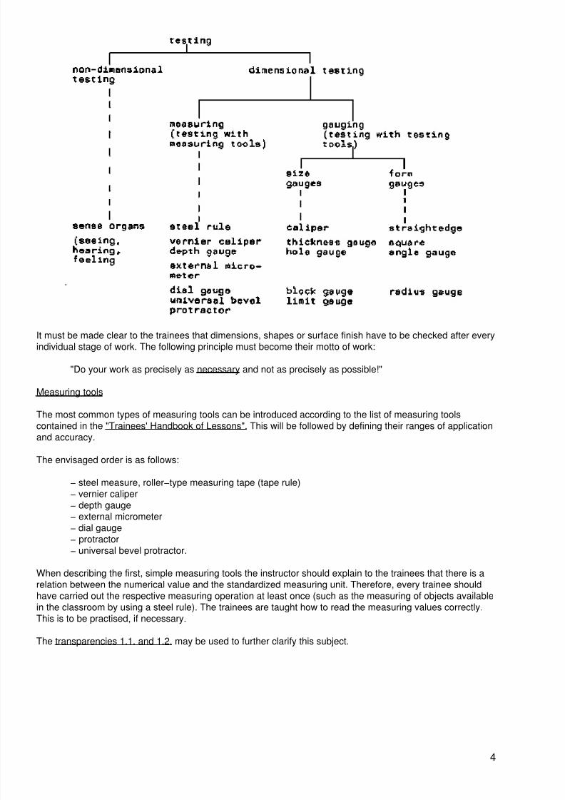
Instruction is to begin with clear−cut definitions of the terms and concepts. The trainees have to learn thatthere is a distinction between testing procedures with measuring tools (measuring) and testing procedureswith testing tools (gauging). The following survey is to facilitate the classification of terms:
3
8/8/2019 En Metalwork Measuring and Testing for Instructors
http://slidepdf.com/reader/full/en-metalwork-measuring-and-testing-for-instructors 8/22
It must be made clear to the trainees that dimensions, shapes or surface finish have to be checked after everyindividual stage of work. The following principle must become their motto of work:
"Do your work as precisely as necessary and not as precisely as possible!"
Measuring tools
The most common types of measuring tools can be introduced according to the list of measuring toolscontained in the "Trainees' Handbook of Lessons". This will be followed by defining their ranges of applicationand accuracy.
The envisaged order is as follows:
− steel measure, roller−type measuring tape (tape rule)− vernier caliper− depth gauge− external micrometer− dial gauge− protractor− universal bevel protractor.
When describing the first, simple measuring tools the instructor should explain to the trainees that there is arelation between the numerical value and the standardized measuring unit. Therefore, every trainee shouldhave carried out the respective measuring operation at least once (such as the measuring of objects availablein the classroom by using a steel rule). The trainees are taught how to read the measuring values correctly.This is to be practised, if necessary.
The transparencies 1.1. and 1.2. may be used to further clarify this subject.
4

8/8/2019 En Metalwork Measuring and Testing for Instructors
http://slidepdf.com/reader/full/en-metalwork-measuring-and-testing-for-instructors 9/22
Transparency 1.1.
5

8/8/2019 En Metalwork Measuring and Testing for Instructors
http://slidepdf.com/reader/full/en-metalwork-measuring-and-testing-for-instructors 10/22
Transparency 1.2.
Experience shows that trainees find it difficult to handle the vernier caliper at the beginning.
Transparency 1.3. should be used to demonstrate the procedure of reading measuring values at this device.
6
8/8/2019 En Metalwork Measuring and Testing for Instructors
http://slidepdf.com/reader/full/en-metalwork-measuring-and-testing-for-instructors 11/22
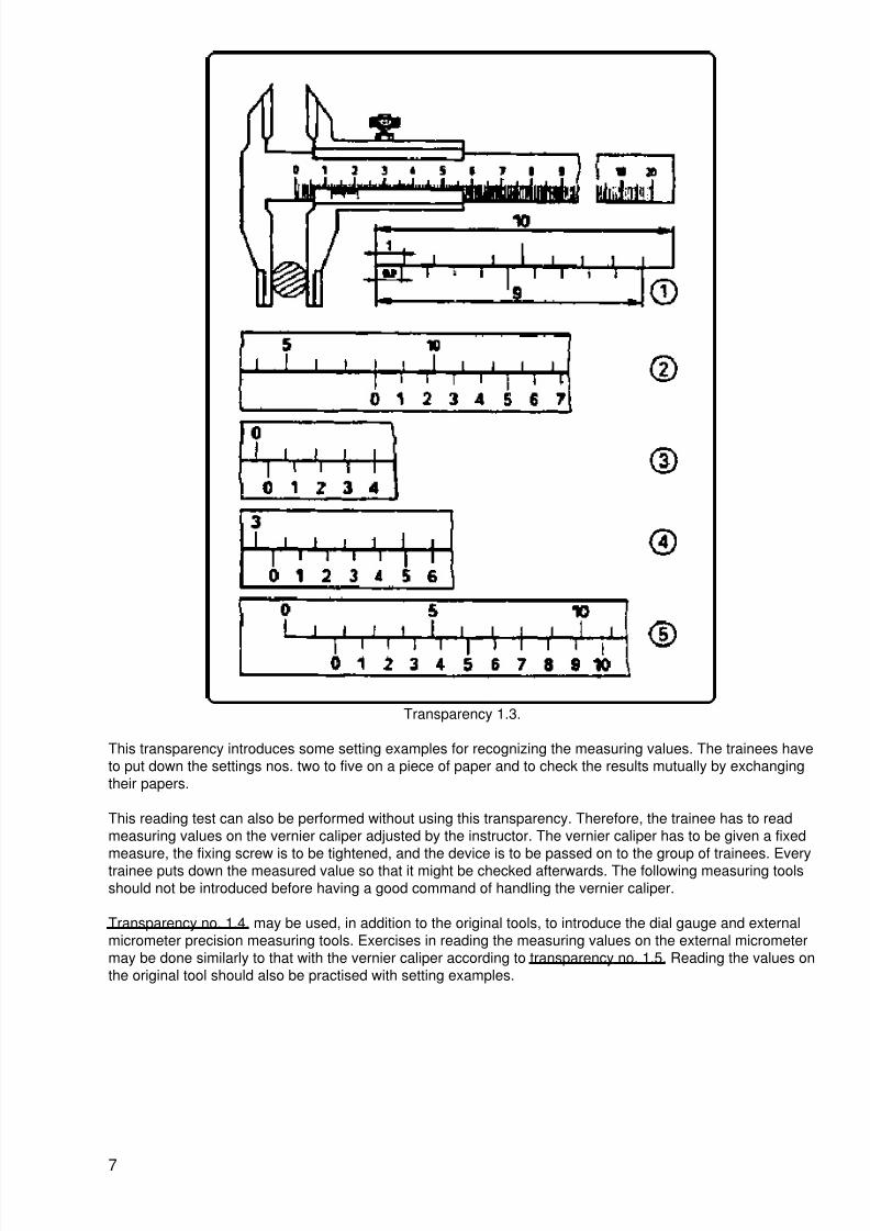
Transparency 1.3.
This transparency introduces some setting examples for recognizing the measuring values. The trainees haveto put down the settings nos. two to five on a piece of paper and to check the results mutually by exchangingtheir papers.
This reading test can also be performed without using this transparency. Therefore, the trainee has to readmeasuring values on the vernier caliper adjusted by the instructor. The vernier caliper has to be given a fixedmeasure, the fixing screw is to be tightened, and the device is to be passed on to the group of trainees. Everytrainee puts down the measured value so that it might be checked afterwards. The following measuring toolsshould not be introduced before having a good command of handling the vernier caliper.
Transparency no. 1.4. may be used, in addition to the original tools, to introduce the dial gauge and externalmicrometer precision measuring tools. Exercises in reading the measuring values on the external micrometermay be done similarly to that with the vernier caliper according to transparency no. 1.5. Reading the values onthe original tool should also be practised with setting examples.
7

8/8/2019 En Metalwork Measuring and Testing for Instructors
http://slidepdf.com/reader/full/en-metalwork-measuring-and-testing-for-instructors 12/22
Transparency 1.4.
Transparency 1.5.
Using the dial gauge may be demonstrated as follows:
The dial gauge rests on its support − a square−shaped workpiece with parallel bottom and top surfaces is tobe put under the tracer pin which is slightly thrown in. The dial gauge scale is adjusted to "Zero" and the limitpointers are set at 10/100 mm on the right and left side of "Zero".
Now the workpiece is to be moved to and fro under the tracer pin. The trainees can be shown that theindicator position beyond the limit pointers means that the range of tolerance has been exceeded.
8

8/8/2019 En Metalwork Measuring and Testing for Instructors
http://slidepdf.com/reader/full/en-metalwork-measuring-and-testing-for-instructors 13/22
The trainees have to learn what the term "tolerance" means. It is to be made clear to the trainees that anindicator position within the range of tolerance means that the quality is still "good".
When describing the instruments for angular measurement, special emphasis is to be laid on handling theuniversal bevel protractor, as it guarantees a universal use. Transparency no. 1.6. can be used for furtherclarification.
Transparency 1.6.
After these instructions, it is recommended that the topic of faulty measurements should be discussed. Ifpossible, the main causes of such faults should be stated clearly:
− fault with the measuring instrument
− fault due to incorrect handling/use− fault caused by environmental circumstances.
These instructions must be followed by hints for the prevention of such faulty measurements,
Testing tools
The order of testing tools in the list contained in the "Trainees' Handbook of Lessons" is to be followed whenexplaining the use of these testing tools. First you should deal with the size gauges and make clear how theydiffer from form gauges. The definition of the terms contained in the "Trainees' Handbook of Lessons" may beused to explain this difference.
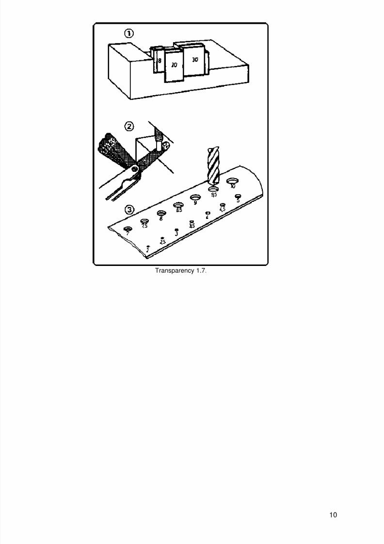
Transparency no. 1.7. can serve to illustrate size gauges
− caliper, thickness gauge, hole gauge. Limit gauges can be seen on transparency no. 1.8.
9
8/8/2019 En Metalwork Measuring and Testing for Instructors
http://slidepdf.com/reader/full/en-metalwork-measuring-and-testing-for-instructors 14/22
Transparency 1.7.
10
8/8/2019 En Metalwork Measuring and Testing for Instructors
http://slidepdf.com/reader/full/en-metalwork-measuring-and-testing-for-instructors 15/22
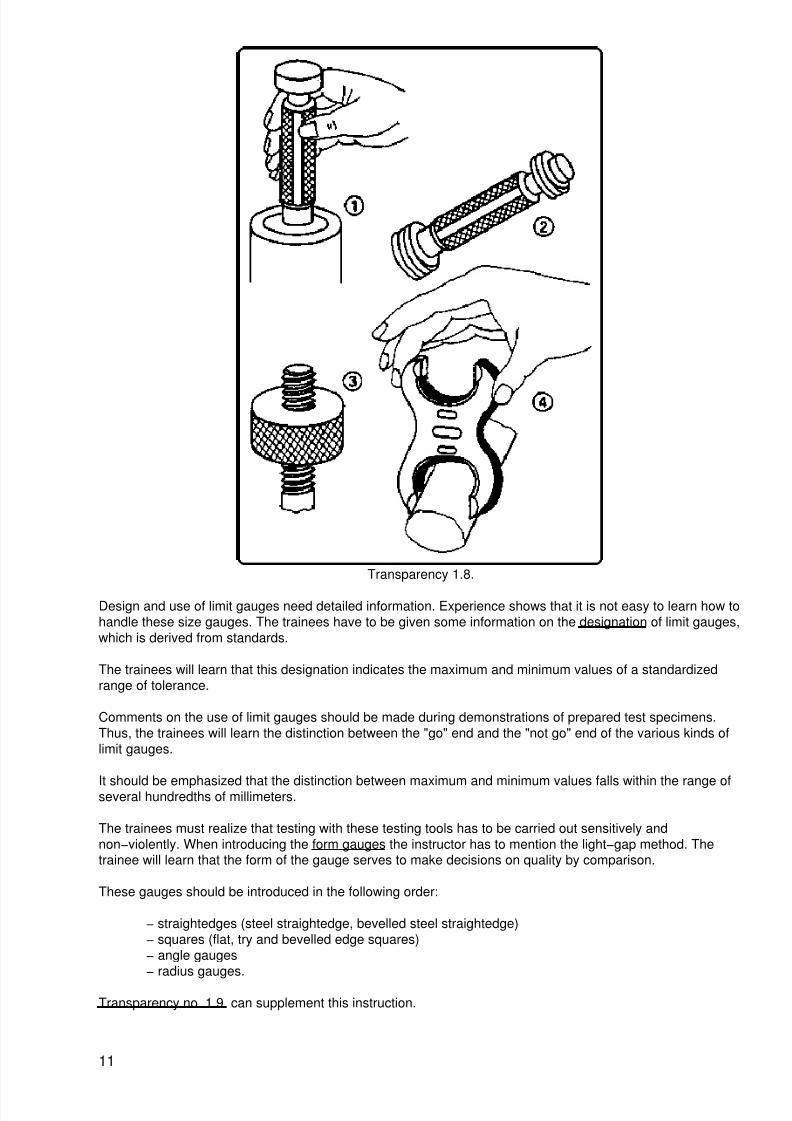
Transparency 1.8.
Design and use of limit gauges need detailed information. Experience shows that it is not easy to learn how tohandle these size gauges. The trainees have to be given some information on the designation of limit gauges,which is derived from standards.
The trainees will learn that this designation indicates the maximum and minimum values of a standardizedrange of tolerance.
Comments on the use of limit gauges should be made during demonstrations of prepared test specimens.Thus, the trainees will learn the distinction between the "go" end and the "not go" end of the various kinds oflimit gauges.
It should be emphasized that the distinction between maximum and minimum values falls within the range ofseveral hundredths of millimeters.
The trainees must realize that testing with these testing tools has to be carried out sensitively andnon−violently. When introducing the form gauges the instructor has to mention the light−gap method. Thetrainee will learn that the form of the gauge serves to make decisions on quality by comparison.
These gauges should be introduced in the following order:
− straightedges (steel straightedge, bevelled steel straightedge)− squares (flat, try and bevelled edge squares)− angle gauges− radius gauges.
Transparency no. 1.9. can supplement this instruction.
11
8/8/2019 En Metalwork Measuring and Testing for Instructors
http://slidepdf.com/reader/full/en-metalwork-measuring-and-testing-for-instructors 16/22
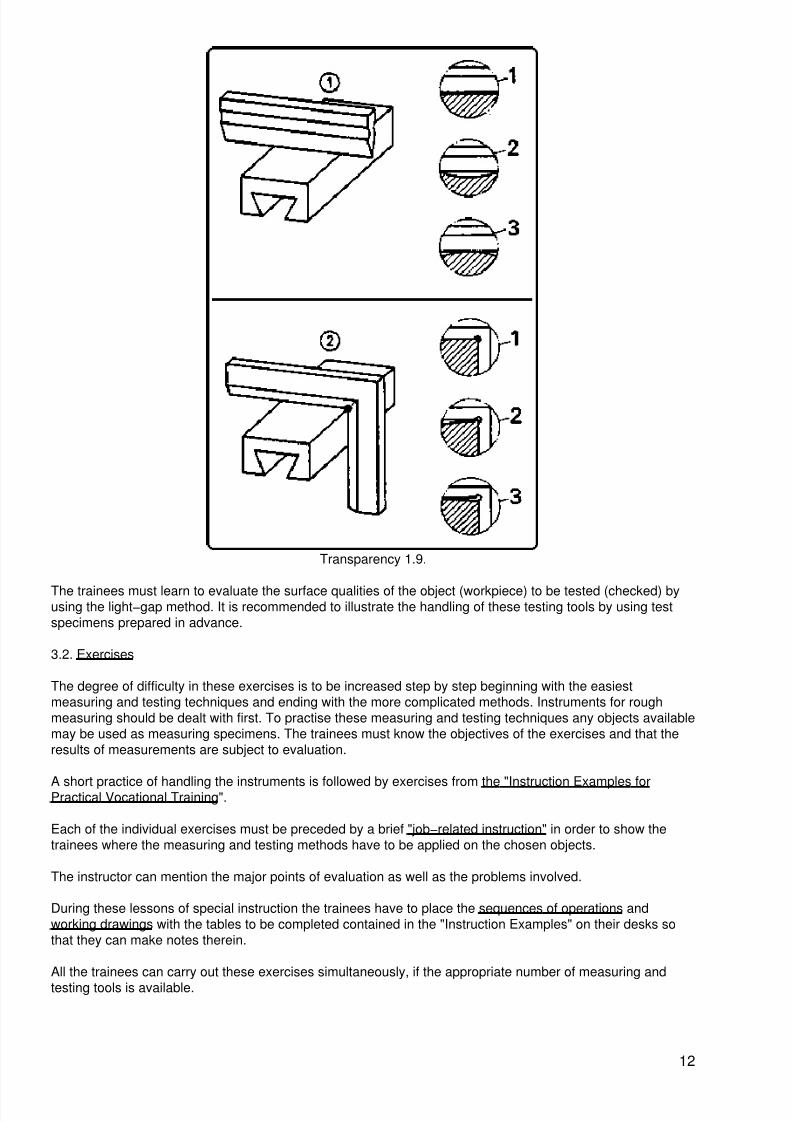
Transparency 1.9.
The trainees must learn to evaluate the surface qualities of the object (workpiece) to be tested (checked) byusing the light−gap method. It is recommended to illustrate the handling of these testing tools by using testspecimens prepared in advance.
3.2. Exercises
The degree of difficulty in these exercises is to be increased step by step beginning with the easiestmeasuring and testing techniques and ending with the more complicated methods. Instruments for roughmeasuring should be dealt with first. To practise these measuring and testing techniques any objects availablemay be used as measuring specimens. The trainees must know the objectives of the exercises and that theresults of measurements are subject to evaluation.
A short practice of handling the instruments is followed by exercises from the "Instruction Examples forPractical Vocational Training".
Each of the individual exercises must be preceded by a brief "job−related instruction" in order to show thetrainees where the measuring and testing methods have to be applied on the chosen objects.
The instructor can mention the major points of evaluation as well as the problems involved.
During these lessons of special instruction the trainees have to place the sequences of operations andworking drawings with the tables to be completed contained in the "Instruction Examples" on their desks sothat they can make notes therein.
All the trainees can carry out these exercises simultaneously, if the appropriate number of measuring andtesting tools is available.
12
8/8/2019 En Metalwork Measuring and Testing for Instructors
http://slidepdf.com/reader/full/en-metalwork-measuring-and-testing-for-instructors 17/22
This being the case, the trainees can do the necessary exercises by themselves without being pushed by timelimits. If the required number of tools cannot be provided, the waiting trainees should do other jobs in theworkshop. It is a good practice to roughly prepare the initial materials for the subsequent exercises, e.g.selection of materials, sawing and shearing to rough nominal sizes, derusting. deburring etc. These activitiesneed supervision!
3.3. Examples for Recapitulation and Tests
This section contains questions which are to consolidate and test the acquired skills and knowledge. All the
exercises are provided with the necessary answers.
Questions which are also contained in the "Trainees' Handbook of Lessons", are marked with the letter "A".
1. What is the purpose of measuring and testing?
(To check dimensions, shape and surface finish of the work−piece during the manufacturingprocess and to compare the data with the manufacturing drawing.)
2. Which testing methods do you know?
"A" (Dimensional and non−dimensional testing methods.)
3. Which dimensional testing methods do you know?
(Testing with measuring tools and testing with testing tools (gauges).)
4. What is the difference between measuring and gauging?
"A" (Measuring serves to determine the exact sizes and dimensions; gauging serves to findout deviations from dimensions and shapes limited by a certain range of tolerance.)
5. Which measuring tools have a measuring accuracy of 1/10 millimeter?
"A" (Vernier caliper, depth gauge.)
6. Which measuring tools are used for precision measurements of 1/100 millimeter measuringaccuracy?
"A" (External micrometer, internal micrometer, depth micrometer, dial gauge.)
7. How do the individual types of instruments for angular measurements differ?
"A" (Protractors with a range of 0 − 180 degrees for rough measurements; universal bevelprotractors with a range of 0 − 360 degrees for precision measurements.)
8. Which measuring faults do you know?
(Faulty measuring instrument, faulty handling, environmental influences.)
9. How can we avoid faulty measuring?
"A" (Repeated measuring; use of faultless measuring instruments, proper handling of theseinstruments; provision of a clean and well−lit workbench; measuring under the sametemperature conditions.)
10. What is the difference between measuring and testing tools?
"A" (Measuring tools are provided with scales to read the measuring value; testing tools do
not have scales but only the designation of the measure.)
11. What are size gauges?
13

8/8/2019 En Metalwork Measuring and Testing for Instructors
http://slidepdf.com/reader/full/en-metalwork-measuring-and-testing-for-instructors 18/22
(Instruments to determine sizes or to check whether or not existing dimensions on an objectare within the stipulated limits.)
12. What are the special features of limit gauges compared to simple size gauges?
"A" (They mostly comprise two size gauges for the maximum and minimum size and are usedwith standardized and very close ranges of tolerance.)
13. Which testing method is typical of using the cylindrical limit plug gauge?
"A" (The "go" end must fit easily into the true−to−size bore hole, the "not go" end must not.)
14. Which testing results do we obtain if we use limit screw plug gauges?
"A" (Result: "go" or "not go", "go" does not say anything about external quality criteria.)
15. What are form gauges?
(Instruments to check flatness, angles and accuracy of radius.)
16. Which testing method is typical of form gauges?
"A" (Light−gap method − comparison of gauge and workpiece through light incidence; lightincidence must be uniform.)
17. How do squares and angle gauges differ?
"A" (Squares are used to check the squareness of surfaces or edges/e.g. 90 degrees/; anglegauges are designed for specific angles/e.g. 55 degrees/.)
18. Which are the main principles to be observed when employing measuring and testingtools?
"A" (Keep measuring and testing tools separate from cutting or hand tools, place them on softpads, protect them shocks and dropping.)
4. Application of the working techniques of "Measuring and Testing"
The sequence of exercises can focus on one subject according to the variant mentioned in section 3 or it maybe divided into several stages.
The "Instruction Examples for Practical Vocational Training −Measuring and Testing" provide 8 exercises, thedegree of difficulty of which increases gradually.
These "Instruction Examples ..." comprise a list of materials required (initial material, measuring and testing
tools, accessories) as well as the sequence of operations and an illustrative working drawing.
Thus, the trainees avail of the necessary information to begin their exercise−related work.
The selection of exercises takes into consideration that in the majority of cases there are no manufacturedpieces of work available and that the acquisition of measuring and testing techniques will be the first activitiesat the beginning of the course for such trainees. That is the reason why we have chosen objects which usuallyare available at the workbench or in the workshop.
4.1. Instruction Examples
What follows is a short description of the individual training examples in order to give a survey of those objects
at which the prior knowledge is to be verified.
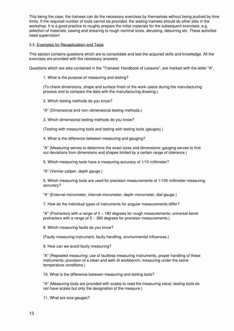
Instruction Example 1.1.Try Square
14
8/8/2019 En Metalwork Measuring and Testing for Instructors
http://slidepdf.com/reader/full/en-metalwork-measuring-and-testing-for-instructors 19/22
This testing tool shall serve as an object for simple rough and precise linear measurements by means of thesteel rule, vernier caliper, depth gauge as well as for flatness testing by means of the bevelled steelstraightedge.
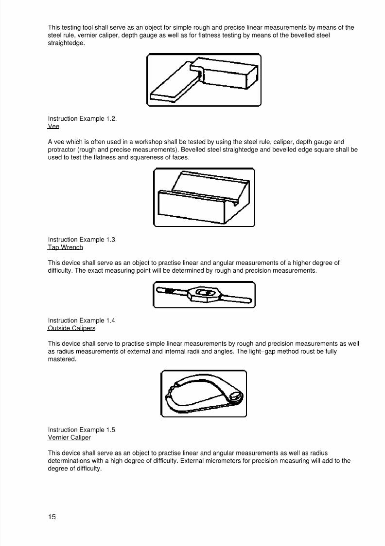
Instruction Example 1.2.Vee
A vee which is often used in a workshop shall be tested by using the steel rule, caliper, depth gauge andprotractor (rough and precise measurements). Bevelled steel straightedge and bevelled edge square shall beused to test the flatness and squareness of faces.
Instruction Example 1.3.Tap Wrench
This device shall serve as an object to practise linear and angular measurements of a higher degree ofdifficulty. The exact measuring point will be determined by rough and precision measurements.
Instruction Example 1.4.Outside Calipers
This device shall serve to practise simple linear measurements by rough and precision measurements as wellas radius measurements of external and internal radii and angles. The light−gap method roust be fullymastered.
Instruction Example 1.5.Vernier Caliper
This device shall serve as an object to practise linear and angular measurements as well as radiusdeterminations with a high degree of difficulty. External micrometers for precision measuring will add to thedegree of difficulty.
15

8/8/2019 En Metalwork Measuring and Testing for Instructors
http://slidepdf.com/reader/full/en-metalwork-measuring-and-testing-for-instructors 20/22
Instruction Example 1.6.Hexagonal−Head Bolt and Nut
In addition to simple linear and angle measurements, the thread is to be determined by using a limit gauge inorder to check whether the external and internal threads are true to size.
Instruction Example 1.7.Block Gauge
Some block gauges are arranged side by side so that differences can be measured by using a dial gauge.The skill of handling external micrometers is to be consolidated.
Instruction Example 1.8.Plain Pins
The external micrometer is used to determine the dimensions of diameters; limit snap gauges shall serve tocheck true−to−size dimensions and tolerances according to standard values.
4.2. Criteria for practical training
It is recommended to determine some major points of observation and evaluation when the work is beingcarried out. The following criteria may serve as a guideline:
− Does the trainee handle the measuring and testing tools with care or negligence?
− Does the trainee select the proper measuring tools?
− Are the surfaces to be measured and tested clean or does the trainee use the
measuring/testing tool on surfaces which are not clean?
− Does the trainee read the correct measuring value or are there reading errors?
16

8/8/2019 En Metalwork Measuring and Testing for Instructors
http://slidepdf.com/reader/full/en-metalwork-measuring-and-testing-for-instructors 21/22
− Does the trainee employ the correct measuring force or does he cause damage by applyingtoo much measuring force?
− Does the trainee use the "go" end and "not go" end of the limit gauges properly?
− Does the trainee put the form gauge on the surface properly or does he cant it?
− Does the trainee see the light gap and can be evaluate it?
5. Captions and legends of the "Measuring and Testing" transparencies series
Transparency No. 1.1: Application of the Steel Rule
Transparency No. 1.2.: Design and Application of Vernier Caliper
(1) Vernier caliper
1 fixed jaw with measuring scale2 sliding jaw with vernier3 measuring jaw for external measurements
4 measuring jaw for internal measurements5 clamping screw6 depth gauge
(2) Vernier with a set measure of 20.8 mm
Transparency No. 1.3.: Vernier Caliper Setting Examples
(1) Comparison of length of scale units and vernier units in millimeters(2) Setting of 8 mm(3) Setting of 0.4 mm(4) Setting of 3.6 mm
(5) Setting of 1.7 mm
Transparency No. 1.4.: Design and Application of Precision Measuring Tools
(1) Dial Gauge
1 dial gauge2 tolerance pointer3 millimeter indicator4 0.01 millimeter indicator5 tracer pin6 workpiece7 support
(2) External Micrometer
1 tracer screw2 case3 dial for 50/100 millimeter indication4 dial for whole and half millimeters5 clamping nut (locking)6 sliding tracer pin (measuring screw)7 fixed tracer pin (anvil)8 frame
Transparency No. 1.5. Setting Examples at the ExternalMicrometer
17

8/8/2019 En Metalwork Measuring and Testing for Instructors
http://slidepdf.com/reader/full/en-metalwork-measuring-and-testing-for-instructors 22/22
(1) 8.27 mm setting(2) 13.01 mm setting(3) 8.77 mm setting(4) 0.59 mm setting
Transparency No. 1.6. Design and Application of Instrumentsfor Angular Measurements
(1) Protractor (120 degrees' setting)
(2) universal bevel protractor (150 degrees' setting)
1 scale with 4 x 90 degrees' division2 vernier3 locking knob for scale4 locking knob for measuring jaw5 adjustable measuring jaw6 fixed measuring jaw (stop)
Transparency No. 1.7.Application of Size Gauges
(1) Testing of a stepped groove by block gauges(2) Testing of a narrow clearance by a thickness gauge(3) Testing of a drill diameter by hole gauges
Transparency No. 1.8.Application of Limit Gauges
(1) Testing of a true−to−size bore hole by a cylindrical limit plug gauge(2) Limit screw plug gauge(3) Testing a bolt by the ring thread gauge(4) Testing a shaft diameter by the limit snap gauge
Transparency No. 1.9.Application of Form Gauges
(1) Testing the flatness by the bevelled steel straightedge
1 flat surface2 hollow surface3 crowned surface
(2) Testing of squareness (90) by the bevelled edge square
1 exact angle2 angle too small
3 angle too big
List of Captions
Figures 1 through 9 according to transparencies 1.1. through 1.9.
Figures 10 through 17 according to instruction examples 1.1. through 1.8.