en / emergency stop, stop category 1 (option +q952) for ... manual. if you ignore them, injury or...
TRANSCRIPT

Options for ABB drives
User’s manualEmergency stop, stop category 1 (option +Q952) for ACS880-07/17/37 drives

List of related manuals
You can find manuals and other product documents in PDF format on the Internet. See section Document library on the Internet on the inside of the back cover. For manuals not available in the Document library, contact your local ABB representative.
Drive hardware manuals and guides Code (English)
ACS880-07 drives (560 to 2800 kW) hardware manual 3AUA0000143261
ACS880-07 drives (45 to 630 kW, 50 to 700 hp) hardware manual
3AUA0000105718
ACS880-17 hardware manual 3AXD50000020436
ACS880-37 hardware manual 3AXD50000020437
Drive firmware manuals and guides
ACS880 primary control program firmware manual 3AUA0000085967
ACS880 primary control program quick start-up guide 3AUA0000098062
ACS880 diode supply control program firmware manual 3AUA0000103295
ACS880 IGBT supply control program firmware manual 3AUA0000131562
PC tool manuals
Start-up and maintenance PC tool Drive composer user’s manual
3AUA0000094606
Functional safety design tool user’s manual 3AXD10000102417
Option manuals and guides
ACS-AP-x Assistant control panels user’s manual 3AUA0000085685
Functional safety; Technical guide No. 10 3AUA0000048753
Safety and functional safety; A general guide 1SFC001008B0201
ABB Safety information and solutions www.abb.com/safety
Manuals and quick guides for I/O extension modules, fieldbus adapters, etc.
ACS880-07 (45 to 630 kW) manuals
ACS880-07 (560 to 2800 kW) manuals
ACS880-17 manuals ACS880-37 manuals

User’s manual
Emergency stop, stop category 1 (option +Q952) for ACS880-07/17/37 drives
3AUA0000119896 Rev EEN
EFFECTIVE: 2016-01-15
2016 ABB Oy. All Rights Reserved.
Table of contents


5
Table of contents
List of related manuals . . . . . . . . . . . . . . . . . . . . . . . . . . . . . . . . . . . . . . . . . . . . . . . . . . . 2
1. Introduction to the manual
Contents this chapter . . . . . . . . . . . . . . . . . . . . . . . . . . . . . . . . . . . . . . . . . . . . . . . . . . . . 7Applicability . . . . . . . . . . . . . . . . . . . . . . . . . . . . . . . . . . . . . . . . . . . . . . . . . . . . . . . . . . . . 7Safety instructions . . . . . . . . . . . . . . . . . . . . . . . . . . . . . . . . . . . . . . . . . . . . . . . . . . . . . . . 8Target audience . . . . . . . . . . . . . . . . . . . . . . . . . . . . . . . . . . . . . . . . . . . . . . . . . . . . . . . . 8Contents . . . . . . . . . . . . . . . . . . . . . . . . . . . . . . . . . . . . . . . . . . . . . . . . . . . . . . . . . . . . . . 8Related documents . . . . . . . . . . . . . . . . . . . . . . . . . . . . . . . . . . . . . . . . . . . . . . . . . . . . . . 8Abbreviations . . . . . . . . . . . . . . . . . . . . . . . . . . . . . . . . . . . . . . . . . . . . . . . . . . . . . . . . . . 9Exclusion of liability . . . . . . . . . . . . . . . . . . . . . . . . . . . . . . . . . . . . . . . . . . . . . . . . . . . . . 10Quick reference guide for implementing a safety system . . . . . . . . . . . . . . . . . . . . . . . . 10
2. Option description and instructions
Contents this chapter . . . . . . . . . . . . . . . . . . . . . . . . . . . . . . . . . . . . . . . . . . . . . . . . . . . 11Description . . . . . . . . . . . . . . . . . . . . . . . . . . . . . . . . . . . . . . . . . . . . . . . . . . . . . . . . . . . 11Operation principle . . . . . . . . . . . . . . . . . . . . . . . . . . . . . . . . . . . . . . . . . . . . . . . . . . . . . 12
ACS880-07 drives, frames R6 to R11 . . . . . . . . . . . . . . . . . . . . . . . . . . . . . . . . . . . . 12ACS880-07 drives, frames nxDXT + nxR8 . . . . . . . . . . . . . . . . . . . . . . . . . . . . . . . . . 14ACS880-17/37 drives . . . . . . . . . . . . . . . . . . . . . . . . . . . . . . . . . . . . . . . . . . . . . . . . . 16
Fault reaction function . . . . . . . . . . . . . . . . . . . . . . . . . . . . . . . . . . . . . . . . . . . . . . . . . . . 17Parameter settings . . . . . . . . . . . . . . . . . . . . . . . . . . . . . . . . . . . . . . . . . . . . . . . . . . . . . 18
ACS880-07/17/37 drives, all frame sizes . . . . . . . . . . . . . . . . . . . . . . . . . . . . . . . . . . 18ACS880-07 drives, frames nxDXT + nxR8i and ACS880-17/37 drives . . . . . . . . . . . 18
Hardware settings . . . . . . . . . . . . . . . . . . . . . . . . . . . . . . . . . . . . . . . . . . . . . . . . . . . . . . 19Wiring . . . . . . . . . . . . . . . . . . . . . . . . . . . . . . . . . . . . . . . . . . . . . . . . . . . . . . . . . . . . . . . 20Start-up and acceptance test . . . . . . . . . . . . . . . . . . . . . . . . . . . . . . . . . . . . . . . . . . . . . 21
Checks and settings with no voltage connected . . . . . . . . . . . . . . . . . . . . . . . . . . 21Settings with voltage connected . . . . . . . . . . . . . . . . . . . . . . . . . . . . . . . . . . . . . . 21Acceptance test . . . . . . . . . . . . . . . . . . . . . . . . . . . . . . . . . . . . . . . . . . . . . . . . . . . 21
Use of the safety function . . . . . . . . . . . . . . . . . . . . . . . . . . . . . . . . . . . . . . . . . . . . . . . . 22Activating . . . . . . . . . . . . . . . . . . . . . . . . . . . . . . . . . . . . . . . . . . . . . . . . . . . . . . . . . . 22Resetting . . . . . . . . . . . . . . . . . . . . . . . . . . . . . . . . . . . . . . . . . . . . . . . . . . . . . . . . . . 22
Emergency stop indications . . . . . . . . . . . . . . . . . . . . . . . . . . . . . . . . . . . . . . . . . . . . . . 22Fault tracing . . . . . . . . . . . . . . . . . . . . . . . . . . . . . . . . . . . . . . . . . . . . . . . . . . . . . . . . . . 23
ACS880-07 drives, frames R6 to R11 . . . . . . . . . . . . . . . . . . . . . . . . . . . . . . . . . . 23Maintenance . . . . . . . . . . . . . . . . . . . . . . . . . . . . . . . . . . . . . . . . . . . . . . . . . . . . . . . . . . 24
Proof test interval . . . . . . . . . . . . . . . . . . . . . . . . . . . . . . . . . . . . . . . . . . . . . . . . . . . . 24Competence . . . . . . . . . . . . . . . . . . . . . . . . . . . . . . . . . . . . . . . . . . . . . . . . . . . . . . . . 24Residual risk . . . . . . . . . . . . . . . . . . . . . . . . . . . . . . . . . . . . . . . . . . . . . . . . . . . . . . . . 24Intentional misuse . . . . . . . . . . . . . . . . . . . . . . . . . . . . . . . . . . . . . . . . . . . . . . . . . . . . 25Decommissioning . . . . . . . . . . . . . . . . . . . . . . . . . . . . . . . . . . . . . . . . . . . . . . . . . . . . 25
Safety data . . . . . . . . . . . . . . . . . . . . . . . . . . . . . . . . . . . . . . . . . . . . . . . . . . . . . . . . . . . 26Safety data values . . . . . . . . . . . . . . . . . . . . . . . . . . . . . . . . . . . . . . . . . . . . . . . . . . . 26
ACS880-07 drives with a main contactor . . . . . . . . . . . . . . . . . . . . . . . . . . . . . . . 27ACS880-17/37 drives with a main contactor . . . . . . . . . . . . . . . . . . . . . . . . . . . . . 29ACS880-07/17/37 drives with a main circuit breaker . . . . . . . . . . . . . . . . . . . . . . . 29
Safety component types . . . . . . . . . . . . . . . . . . . . . . . . . . . . . . . . . . . . . . . . . . . . . . . 29
6
Safety block diagrams . . . . . . . . . . . . . . . . . . . . . . . . . . . . . . . . . . . . . . . . . . . . . . . . 29Relevant failure modes . . . . . . . . . . . . . . . . . . . . . . . . . . . . . . . . . . . . . . . . . . . . . . . 31Fault exclusions . . . . . . . . . . . . . . . . . . . . . . . . . . . . . . . . . . . . . . . . . . . . . . . . . . . . 31Operation delays . . . . . . . . . . . . . . . . . . . . . . . . . . . . . . . . . . . . . . . . . . . . . . . . . . . . 31
General rules, notes and definitions . . . . . . . . . . . . . . . . . . . . . . . . . . . . . . . . . . . . . . . 32Validation of the safety functions . . . . . . . . . . . . . . . . . . . . . . . . . . . . . . . . . . . . . . . 32
Authorized person . . . . . . . . . . . . . . . . . . . . . . . . . . . . . . . . . . . . . . . . . . . . . . . . 32Validation procedure . . . . . . . . . . . . . . . . . . . . . . . . . . . . . . . . . . . . . . . . . . . . . . . 32Acceptance test reports . . . . . . . . . . . . . . . . . . . . . . . . . . . . . . . . . . . . . . . . . . . . 32Competence . . . . . . . . . . . . . . . . . . . . . . . . . . . . . . . . . . . . . . . . . . . . . . . . . . . . . 32
Ambient conditions . . . . . . . . . . . . . . . . . . . . . . . . . . . . . . . . . . . . . . . . . . . . . . . . . . 33ACS880-07 drives, frames R6 to R11 . . . . . . . . . . . . . . . . . . . . . . . . . . . . . . . . . 33
Reporting problems and failures related to safety functions . . . . . . . . . . . . . . . . . . . 33Related standards and directives . . . . . . . . . . . . . . . . . . . . . . . . . . . . . . . . . . . . . . . . . 34
Compliance with the European Machinery Directive . . . . . . . . . . . . . . . . . . . . . . . . . 34
Further information
Product and service inquiries . . . . . . . . . . . . . . . . . . . . . . . . . . . . . . . . . . . . . . . . . . . . . . 35Product training . . . . . . . . . . . . . . . . . . . . . . . . . . . . . . . . . . . . . . . . . . . . . . . . . . . . . . . . 35Providing feedback on ABB Drives manuals . . . . . . . . . . . . . . . . . . . . . . . . . . . . . . . . . . 35Document library on the Internet . . . . . . . . . . . . . . . . . . . . . . . . . . . . . . . . . . . . . . . . . . . 35

Introduction to the manual 7
1
Introduction to the manual
Contents this chapterThis chapter describes the manual in short and gives some general information for the reader. The chapter also contains a quick reference for implementing a safety system.
ApplicabilityThe manual applies to ACS880-07/17/37 drives which have the option: Emergency stop, stop category 1 with main contactor/circuit breaker, with safety relays (option +Q952). For the option +Q952, ABB installs the FIO-01 digital I/O extension module (option +L501) to the drive.

8 Introduction to the manual
Safety instructionsOnly a qualified electrician who has appropriate knowledge on functional/machine/process safety is allowed to install, start up and maintain the safety circuit.
WARNING! After making additions to the drive safety circuit or modifying it, or changing circuit boards inside the drive, always test the functioning of the safety circuit according to the acceptance test procedure. Any changes in the electrical
installations of the drive may affect the safety performance or operation of the drive unexpectedly. All customer-made changes are on the customer’s responsibility.
WARNING! Read and obey all safety instructions given for the drive in its hardware manual. If you ignore them, injury or death, or damage to the equipment can occur.
This manual does not repeat the complete safety instructions of the drive but it only includes the instructions related to the scope of this manual.
Target audienceThe manual is intended for people who install, start up, use and service the safety option of the drive. Read the manual before working on the drive. You are expected to know the fundamentals of electricity, wiring, electrical components, electrical schematic symbols, and functional safety.
ContentsThe chapters of this manual are briefly described below.
Introduction to the manual (this chapter) introduces this manual.
Option description and instructions describes the safety option and instructs how to wire, start up, test, validate, use and maintain it. The chapter also contains the safety data.
Related documents
• Product manuals (see the inside of the front cover)
• Circuit diagrams delivered with the drive
• Part lists delivered with the drive
• Safety data report (if the safety circuit is application engineered)
Introduction to the manual 9
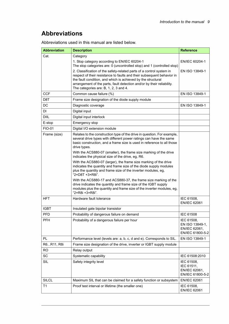
AbbreviationsAbbreviations used in this manual are listed below.
Abbreviation Description Reference
Cat. Category
1. Stop category according to EN/IEC 60204-1The stop categories are: 0 (uncontrolled stop) and 1 (controlled stop)
2. Classification of the safety-related parts of a control system in respect of their resistance to faults and their subsequent behavior in the fault condition, and which is achieved by the structural arrangement of the parts, fault detection and/or by their reliability. The categories are: B, 1, 2, 3 and 4.
EN/IEC 60204-1
EN ISO 13849-1
CCF Common cause failure (%) EN ISO 13849-1
D8T Frame size designation of the diode supply module
DC Diagnostic coverage EN ISO 13849-1
DI Digital input
DIIL Digital input interlock
E-stop Emergency stop
FIO-01 Digital I/O extension module
Frame (size) Relates to the construction type of the drive in question. For example, several drive types with different power ratings can have the same basic construction, and a frame size is used in reference to all those drive types.
With the ACS880-07 (smaller), the frame size marking of the drive indicates the physical size of the drive, eg, R6.
With the ACS880-07 (larger), the frame size marking of the drive indicates the quantity and frame size of the diode supply modules plus the quantity and frame size of the inverter modules, eg, “2×D8T +3×R8i”.
With the ACS880-17 and ACS880-37, the frame size marking of the drive indicates the quantity and frame size of the IGBT supply modules plus the quantity and frame size of the inverter modules, eg, “2×R8i +3×R8i”.
HFT Hardware fault tolerance IEC 61508, EN/IEC 62061
IGBT Insulated gate bipolar transistor
PFD Probability of dangerous failure on demand IEC 61508
PFH Probability of a dangerous failure per hour IEC 61508, EN ISO 13849-1, EN/IEC 62061,EN/IEC 61800-5-2
PL Performance level (levels are: a, b, c, d and e). Corresponds to SIL. EN ISO 13849-1
R6...R11, R8i Frame size designation of the drive, inverter or IGBT supply module
RO Relay output
SC Systematic capability IEC 61508:2010
SIL Safety integrity level IEC 61508, IEC 61511,EN/IEC 62061,EN/IEC 61800-5-2
SILCL Maximum SIL that can be claimed for a safety function or subsystem EN/IEC 62061
T1 Proof test interval or lifetime (the smaller one) IEC 61508, EN/IEC 62061

10 Introduction to the manual
Exclusion of liabilityABB is not responsible for the implementation, verification and validation of the overall safety system. It is the responsibility of the system integrator (or other party) who is responsible for the overall system and system safety.
The system integrator (or other responsible party) must make sure that the entire implementation complies with all relevant standards, directives and local electrical code, and that the system is tested, verified and validated correctly.
Quick reference guide for implementing a safety system
Task
Select the appropriate functional safety standard for the implementation: EN ISO 13849-1, EN/IEC 62061, IEC 61511 or other.
If you select EN/IEC 62061 or IEC 61511, make a safety plan. See EN/IEC 62061 or IEC 61511.
Assess safety: analyze and evaluate risks (estimate SIL/PL) and define risk reduction strategies. Define the safety requirements.
Design the safety system. The part of the design made by ABB is described in chapter Option description and instructions on page 11.
If you made any changes to the delivered safety system, verify the achieved SIL/PL with, for example, FSDT-01 Functional safety design tool or similar. See Functional safety design tool user’s manual (3AXD10000102417 [English]).
Connect the wiring. See section Wiring on page 20.
Set the parameters. See section Parameter settings on page 18.
Validate that the implemented system meets the safety requirements:
• Do the acceptance test. See section Start-up and acceptance test on page 21.
Write the necessary documentation.

Option description and instructions 11
2
Option description and instructions
Contents this chapterThis chapter describes the +Q952 emergency stop option and instructs how to wire, start up, test, validate, use and maintain it. The safety data is also given.
DescriptionThe option +Q952 corresponds to a controlled stop in accordance with stop category 1 (EN/IEC 60204-1). After the user has given the emergency stop command, the drive first decelerates the motor(s) to zero speed according to a preset ramp time. Then, the drive trips the main contactor/breaker which cuts off the input power of the drive.
For the option +Q952, ABB installs the FIO-01 digital I/O extension module (option +L501) to the drive control board (Slot 1).
Note: Drives with the Prevention of unexpected start-up (POUS) option (+Q957): If the user activates the POUS function during the emergency stop deceleration ramp, it overrides the emergency stop function. This activates the Safe torque off (STO) function of the drive immediately and the motor coasts to a stop. For more information on the POUS safety function, see Prevention of unexpected start-up (option +Q957) for ACS880-07/17/37 drives (3AUA0000119910 [English]).
The design principles of the option +Q952 comply with EN ISO13850.
For a list of related standards and European directives, see section Related standards and directives on page 34.

12 Option description and instructions
Operation principle
ACS880-07 drives, frames R6 to R11
- -
+ +
-K21.1 -K63
-K61
RO1
-A412.X
M3~
-Q1/2
~-T1
24 V
DI
-A61
-S61
-A62
-P62
-T22
-K61
~
-S62-Q1/2
-A62
-K63
-Q1/2
L
-K21.1
-K21.1
-A41
XSTO
-A62
FIO-01
OUT
IN1IN2
SGND
-X9691-23-4
Control relays Drive module interface
Main circuit
A41 Control board Q1/2 Main contactorA412.X Digital I/O extension module (FIO-01) P62 Emergency stop indicationA61 Emergency stop safety relay with delay contacts S61 Emergency stop buttonA62 Extension safety relay S62 Emergency stop reset buttonK21.1 Auxiliary safety relay T1 Drive moduleK61 Timer relay T22 24 V power supplyK63 Auxiliary relay X969 STO terminal block
Option description and instructions 13
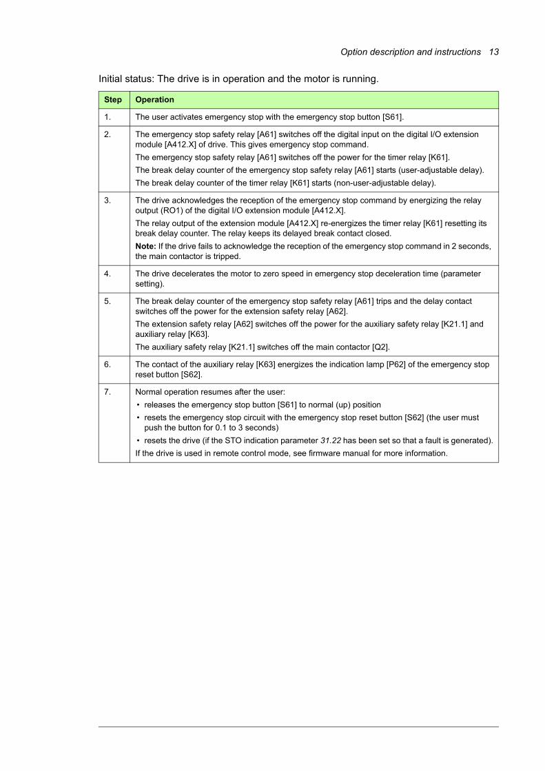
Initial status: The drive is in operation and the motor is running.
Step Operation
1. The user activates emergency stop with the emergency stop button [S61].
2. The emergency stop safety relay [A61] switches off the digital input on the digital I/O extension module [A412.X] of drive. This gives emergency stop command.
The emergency stop safety relay [A61] switches off the power for the timer relay [K61].
The break delay counter of the emergency stop safety relay [A61] starts (user-adjustable delay).
The break delay counter of the timer relay [K61] starts (non-user-adjustable delay).
3. The drive acknowledges the reception of the emergency stop command by energizing the relay output (RO1) of the digital I/O extension module [A412.X].
The relay output of the extension module [A412.X] re-energizes the timer relay [K61] resetting its break delay counter. The relay keeps its delayed break contact closed.
Note: If the drive fails to acknowledge the reception of the emergency stop command in 2 seconds, the main contactor is tripped.
4. The drive decelerates the motor to zero speed in emergency stop deceleration time (parameter setting).
5. The break delay counter of the emergency stop safety relay [A61] trips and the delay contact switches off the power for the extension safety relay [A62].
The extension safety relay [A62] switches off the power for the auxiliary safety relay [K21.1] and auxiliary relay [K63].
The auxiliary safety relay [K21.1] switches off the main contactor [Q2].
6. The contact of the auxiliary relay [K63] energizes the indication lamp [P62] of the emergency stop reset button [S62].
7. Normal operation resumes after the user:
• releases the emergency stop button [S61] to normal (up) position
• resets the emergency stop circuit with the emergency stop reset button [S62] (the user must push the button for 0.1 to 3 seconds)
• resets the drive (if the STO indication parameter 31.22 has been set so that a fault is generated).
If the drive is used in remote control mode, see firmware manual for more information.

14 Option description and instructions
ACS880-07 drives, frames nxDXT + nxR8
-K62.3
-K61
M3~
-Q1/2
~-T1
24 V
-A61-S61
-P62
-T22
-K61
~
-S62
-Q1/2
-K62.2
-Q1/2
L
-K62.1
-K62.1
-K62.1
-K62.3
1) -A412.X
DI
-A41
XSTO
-A51
DIIL
-K62.2
+24DI-K62.2
RO1
OUT
IN1IN2
SGND
FIO-01
-X9691-23-4
1) Reset circuit K61 Timer relayA41 Control board (inverter unit) Q1/2 Main contactorA51 Control board (supply unit) S61 Emergency stop buttonA412.X Digital I/O extension module (FIO-01) S62 Emergency stop reset buttonA61 Emergency stop safety relay with delay contacts P62 Emergency stop indication lampK62.1 Auxiliary safety relay T1 Drive moduleK62.2 Auxiliary relay T22 24 V power supplyK62.3 Auxiliary safety relay X969 STO terminal block
Control relays Inverter and supply unit interface
Main circuit

Option description and instructions 15
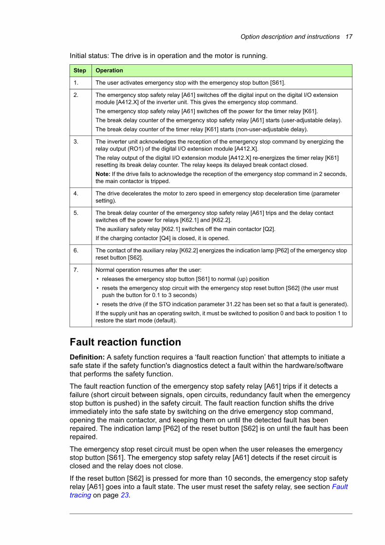
Initial status: The drive is in operation and the motor is running.
Step Operation
1. The user activates emergency stop with the emergency stop button [S61].
2. The emergency stop safety relay [A61] switches off the digital input on the digital I/O extension module [A412.X] of the inverter unit. This gives the emergency stop command.
The emergency stop safety relay [A61] switches off the power for the timer relay [K61].
The break delay counter of the emergency stop safety relay [A61] starts (user-adjustable delay).
The break delay counter of the timer relay [K61] starts (non-user-adjustable delay).
3. The inverter unit acknowledges the reception of the emergency stop command by energizing the relay output (RO1) of the digital I/O extension module [A412.X].
The relay output of the digital I/O extension module [A412.X] re-energizes the timer relay [K61] resetting its break delay counter. The relay keeps its delayed break contact closed.
Note: If the drive fails to acknowledge the reception of the emergency stop command in 2 seconds, the main contactor is tripped.
4. The drive decelerates the motor to zero speed in emergency stop deceleration time (parameter setting).
5. The break delay counter of the emergency stop safety relay [A61] trips and the delay contact switches off the power for relays [K62.1] and [K62.2].
The auxiliary safety relay [K62.1] switches off the main contactor [Q2].
6. The contact of the auxiliary relay [K62.2] energizes the indication lamp [P62] of the emergency stop reset button [S62].
7. Normal operation resumes after the user:
• releases the emergency stop button [S61] to normal (up) position
• resets the emergency stop circuit with the emergency stop reset button [S62] (the user must push the button for 0.1 to 3 seconds)
• resets the drive (if the STO indication parameter 31.22 has been set so that a fault is generated).
If the supply unit has an operating switch, it must be switched to position 0 and back to position 1 to restore the start mode (default).
16 Option description and instructions
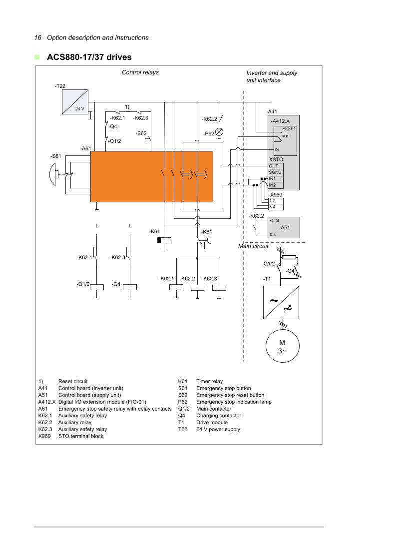
ACS880-17/37 drives
-K62.3
-K61
M3~
-Q1/2
~-T1
24 V
-A61-S61
-P62
-T22
-K61
~
-S62-Q1/2
-K62.2
-Q4
L
-K62.3
-K62.3-K62.1
-K62.1
1)
-A412.X
DI
-A41
XSTO
-A51DIIL
-K62.2
+24DI-K62.2
RO1
OUT
IN1IN2
SGND
FIO-01
-Q1/2
L
-K62.1
-Q4
-X9691-23-4
-Q4
1) Reset circuit K61 Timer relayA41 Control board (inverter unit) S61 Emergency stop buttonA51 Control board (supply unit) S62 Emergency stop reset buttonA412.X Digital I/O extension module (FIO-01) P62 Emergency stop indication lampA61 Emergency stop safety relay with delay contacts Q1/2 Main contactorK62.1 Auxiliary safety relay Q4 Charging contactorK62.2 Auxiliary relay T1 Drive moduleK62.3 Auxiliary safety relay T22 24 V power supplyX969 STO terminal block
Control relays Inverter and supply unit interface
Main circuit
Option description and instructions 17
Initial status: The drive is in operation and the motor is running.
Fault reaction functionDefinition: A safety function requires a ‘fault reaction function’ that attempts to initiate a safe state if the safety function's diagnostics detect a fault within the hardware/software that performs the safety function.
The fault reaction function of the emergency stop safety relay [A61] trips if it detects a failure (short circuit between signals, open circuits, redundancy fault when the emergency stop button is pushed) in the safety circuit. The fault reaction function shifts the drive immediately into the safe state by switching on the drive emergency stop command, opening the main contactor, and keeping them on until the detected fault has been repaired. The indication lamp [P62] of the reset button [S62] is on until the fault has been repaired.
The emergency stop reset circuit must be open when the user releases the emergency stop button [S61]. The emergency stop safety relay [A61] detects if the reset circuit is closed and the relay does not close.
If the reset button [S62] is pressed for more than 10 seconds, the emergency stop safety relay [A61] goes into a fault state. The user must reset the safety relay, see section Fault tracing on page 23.
Step Operation
1. The user activates emergency stop with the emergency stop button [S61].
2. The emergency stop safety relay [A61] switches off the digital input on the digital I/O extension module [A412.X] of the inverter unit. This gives the emergency stop command.
The emergency stop safety relay [A61] switches off the power for the timer relay [K61].
The break delay counter of the emergency stop safety relay [A61] starts (user-adjustable delay).
The break delay counter of the timer relay [K61] starts (non-user-adjustable delay).
3. The inverter unit acknowledges the reception of the emergency stop command by energizing the relay output (RO1) of the digital I/O extension module [A412.X].
The relay output of the digital I/O extension module [A412.X] re-energizes the timer relay [K61] resetting its break delay counter. The relay keeps its delayed break contact closed.
Note: If the drive fails to acknowledge the reception of the emergency stop command in 2 seconds, the main contactor is tripped.
4. The drive decelerates the motor to zero speed in emergency stop deceleration time (parameter setting).
5. The break delay counter of the emergency stop safety relay [A61] trips and the delay contact switches off the power for relays [K62.1] and [K62.2].
The auxiliary safety relay [K62.1] switches off the main contactor [Q2].
If the charging contactor [Q4] is closed, it is opened.
6. The contact of the auxiliary relay [K62.2] energizes the indication lamp [P62] of the emergency stop reset button [S62].
7. Normal operation resumes after the user:
• releases the emergency stop button [S61] to normal (up) position
• resets the emergency stop circuit with the emergency stop reset button [S62] (the user must push the button for 0.1 to 3 seconds)
• resets the drive (if the STO indication parameter 31.22 has been set so that a fault is generated).
If the supply unit has an operating switch, it must be switched to position 0 and back to position 1 to restore the start mode (default).
18 Option description and instructions
Parameter settings
ACS880-07/17/37 drives, all frame sizes
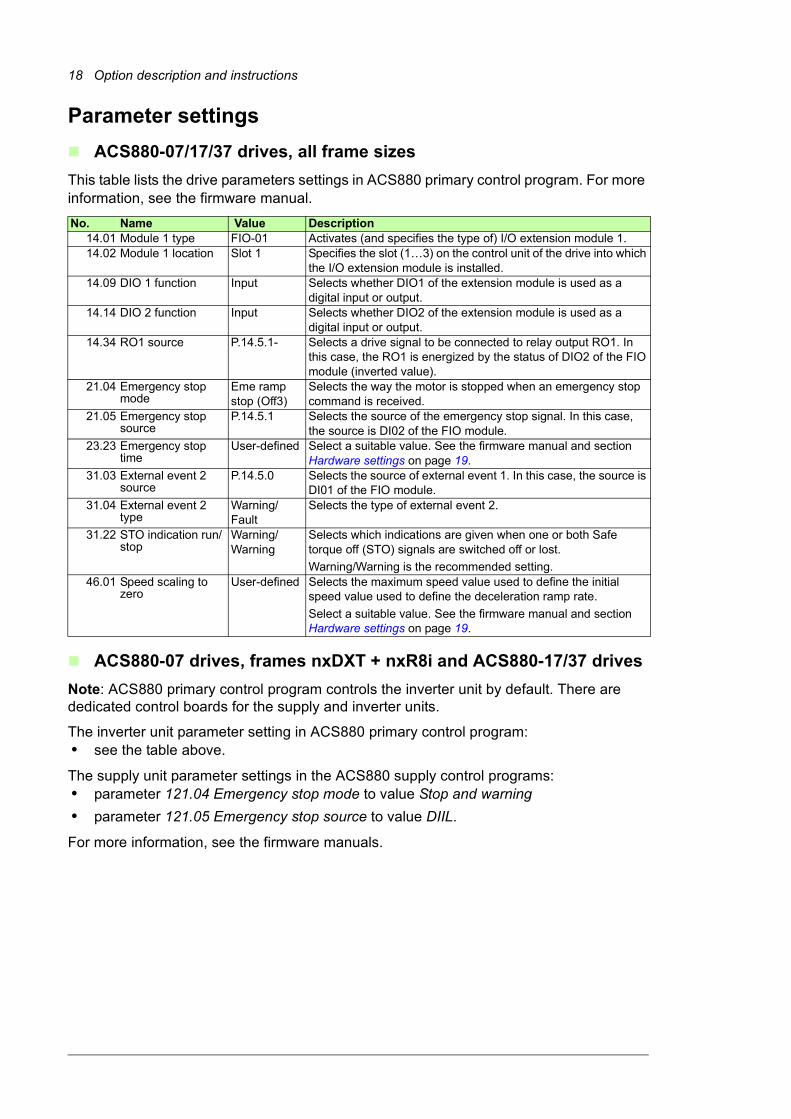
This table lists the drive parameters settings in ACS880 primary control program. For more information, see the firmware manual.
ACS880-07 drives, frames nxDXT + nxR8i and ACS880-17/37 drives
Note: ACS880 primary control program controls the inverter unit by default. There are dedicated control boards for the supply and inverter units.
The inverter unit parameter setting in ACS880 primary control program:• see the table above.
The supply unit parameter settings in the ACS880 supply control programs:• parameter 121.04 Emergency stop mode to value Stop and warning
• parameter 121.05 Emergency stop source to value DIIL.
For more information, see the firmware manuals.
No. Name Value Description14.01 Module 1 type FIO-01 Activates (and specifies the type of) I/O extension module 1.14.02 Module 1 location Slot 1 Specifies the slot (1…3) on the control unit of the drive into which
the I/O extension module is installed.14.09 DIO 1 function Input Selects whether DIO1 of the extension module is used as a
digital input or output.14.14 DIO 2 function Input Selects whether DIO2 of the extension module is used as a
digital input or output.14.34 RO1 source P.14.5.1- Selects a drive signal to be connected to relay output RO1. In
this case, the RO1 is energized by the status of DIO2 of the FIO module (inverted value).
21.04 Emergency stop mode
Eme ramp stop (Off3)
Selects the way the motor is stopped when an emergency stop command is received.
21.05 Emergency stop source
P.14.5.1 Selects the source of the emergency stop signal. In this case, the source is DI02 of the FIO module.
23.23 Emergency stop time
User-defined Select a suitable value. See the firmware manual and section Hardware settings on page 19.
31.03 External event 2 source
P.14.5.0 Selects the source of external event 1. In this case, the source is DI01 of the FIO module.
31.04 External event 2 type
Warning/Fault
Selects the type of external event 2.
31.22 STO indication run/stop
Warning/Warning
Selects which indications are given when one or both Safe torque off (STO) signals are switched off or lost.
Warning/Warning is the recommended setting.46.01 Speed scaling to
zeroUser-defined Selects the maximum speed value used to define the initial
speed value used to define the deceleration ramp rate.
Select a suitable value. See the firmware manual and section Hardware settings on page 19.

Option description and instructions 19
Hardware settings
Set the time delay of the emergency stop safety relay [A61] according to the application needs with the rotary switches on the safety relay.
Example: Required time (tv) = 30 s, set:
• tmax = 30 s and t = 1 (tv = tmax x t = 30 s x 1 = 30 s),
or• tmax = 300 s and t = 0.1 (tv = tmax x t = 300 s x 0.1 = 30 s).
Tune the delay for the emergency stop safety relay [A61] a little longer than the emergency stop deceleration time defined by drive parameters 23.23 and 46.01 (see section Parameter settings on page 18).
Switch Value Description
tFkt 1 Selects the delay mode. Must be 1.
tmax User-defined Selects the time range (in seconds) for the delayed contacts. Value range: 1-300 s.
t User-defined Adjusts the time within the selected range in 10% steps. Value range: 0.1-1.
20 Option description and instructions
WiringOne emergency stop button and one reset button are installed on the cabinet door and wired to the drive at the factory. There are double contacts in the emergency stop button and double wiring (two-channel connection) between the button and the emergency stop safety relay [A61]. The safety relay detects cross faults and faults across one contact from the emergency stop button. This function must be used in a redundant manner, that is, the emergency stop button must be connected to both terminals with a separate contact.
If needed, install additional emergency stop buttons on site and wire them to the appropriate terminal block inside the drive cabinet. See the circuit diagrams delivered with the drive. Follow the rules below:
1. Use only double-contact button approved for the emergency stop circuits.
2. Connect the emergency stop buttons with two conductors (two-channel connection). Note: Keep the channels separate. If you use only one channel, or if the first and second channels are connected together (for example, in a chain), the cross fault detection of the emergency stop safety relay trips and activates the emergency stop command of the drive as it detects a redundancy fault.
3. Use a shielded, twisted pair cable. We recommend a double-shielded cable and gold-plated contacts in the emergency stop button.
4. Ensure that the sum resistance for one channel (loop resistance) from the field to the safety relay does not exceed 1 kohm.
5. Follow the general control cable installation instructions given in the drive hardware manual.
You can also install additional reset buttons and indication lamps for the emergency stop circuit on site. We recommend gold-plated contacts in the reset button. Wire the buttons to the appropriate terminal block inside the drive cabinet. See the circuit diagrams delivered with the drive. Follow the rules below:
1. Sum resistance of the external reset circuit may not exceed 1 kohm.
2. Follow the general control cable installation instructions given in the drive hardware manual.

Option description and instructions 21
Start-up and acceptance testYou need the Drive composer PC tool or a control panel to perform the start-up and acceptance test.
Initial status: Make sure that the drive is ready for use, that is, you have done the tasks of the drive start-up procedure. See the hardware manual.
Action
WARNING! Obey the Safety instructions, page 8. If you ignore them, injury or death, or damage to the equipment can occur.
Checks and settings with no voltage connected
If any connections of emergency stop circuit have been done on site (such as wiring of additional emergency stop buttons, connection of shipping splits of large drives, etc.), check the connections against the appropriate circuit diagrams.
Drives with R8i inverter modules: Check that the STO OUT output on the inverter control unit [A41] is chained to the STO inputs of all inverter modules. The STO circuit is disabled in spare part modules.
Check that the hardware settings relevant to the safety function are set as defined in section Hardware settings on page 19.
Settings with voltage connected
Check that the parameters relevant to the safety function are set as defined in section Parameter settings on page 18.
Acceptance test
Ensure that the motor can be run and stopped freely during the test.
Start the drive and ensure that the motor is running. If possible, use a motor speed close to the maximum speed of the application.
Push the emergency stop button [S61].
Ensure that the drive stops the motor by decelerating and displays a related warning. See section Emergency stop indications on page 22.
Drives with R8i inverter modules: Ensure that “STO hardware failure” (5090) is not generated.
Ensure that the indication lamp [P62] switches on.
Ensure that you cannot switch the power on with the operating switch.
Ensure that you cannot start the drive and motor from any control location: Ensure that the motor does not start even if you switch the start signal off and on or push the start key of the panel.
Turn the emergency stop button [S61] until it releases and returns to the up position.
Push the emergency stop reset button [S62]. Ensure that the indication lamp [P62] switches off.
Switch off the drive start signal.
Power up the drive (see the hardware and firmware manuals).
Restart the drive and motor and check that they operate normally.
Repeat the test from each operating location (every emergency stop button and reset button).
Fill in and sign the acceptance test report which verifies that the safety function is safe and accepted to operation.

22 Option description and instructions
Use of the safety function
Activating
1. Push the emergency stop button [S61]. The emergency stop activates and the button locks in “ON” (open) position.
Resetting
1. Turn the emergency stop button [S61] until it releases.
2. Push the emergency stop reset button [S62] on the cabinet door. The indication lamp [P62] of the reset button [S62] goes out, the emergency stop deactivates. Note: You must push the reset button [S62] for 0.1 to 3 seconds.
3. Reset the drive if necessary.
4. If necessary, close the main contactor with the operating switch (see the hardware and firmware manuals).
The main contactor/breaker closes and the drive is powered up.
5. Make sure that the drive has received the start signal (depends on the configuration, see the firmware manual).
6. You can now restart the drive.
Note: You have to reset the emergency stop circuit with the reset button [S62] also after you have powered up the drive.
Emergency stop indicationsWhen the emergency stop is on:• the drive control program has the warning Emergency stop (off1 or off3) and warning
Safe torque off active.
• the emergency stop reset button [S62] on cabinet door is illuminated (indication lamp [P62]) after the emergency stop deceleration ramp time has passed.
• the ON LED of the emergency stop safety relay [A61] is green and steady.
Option description and instructions 23
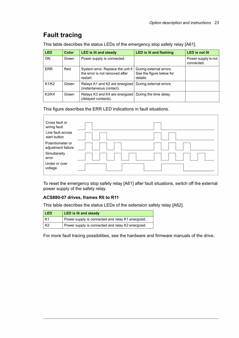
Fault tracingThis table describes the status LEDs of the emergency stop safety relay [A61].
This figure describes the ERR LED indications in fault situations.
To reset the emergency stop safety relay [A61] after fault situations, switch off the external power supply of the safety relay.
ACS880-07 drives, frames R6 to R11
This table describes the status LEDs of the extension safety relay [A62].
For more fault tracing possibilities, see the hardware and firmware manuals of the drive.
LED Color LED is lit and steady LED is lit and flashing LED is not lit
ON Green Power supply is connected. Power supply is not connected.
ERR Red System error. Replace the unit if the error is not removed after restart.
During external errors.See the figure below for details.
K1/K2 Green Relays K1 and K2 are energized(instantaneous contact).
During external errors.
K3/K4 Green Relays K3 and K4 are energized(delayed contacts).
During the time delay.
LED LED is lit and steady
K1 Power supply is connected and relay K1 energized.
K2 Power supply is connected and relay K2 energized.
Cross fault or wiring fault
Line fault across start button
Potentiometer or adjustment failure
Simultaneity error
Under or over voltage
24 Option description and instructions
MaintenanceAfter the operation of the safety function is tested at start-up, it does not need any scheduled maintenance, excluding the main contactor which has a limited lifetime. Replace the contactor before the end of its lifetime. See the contactor data sheet or manual. Repeat the acceptance test for the function after the replacement. See section Start-up and acceptance test (page 21).
In addition to proof testing, it is a good practice to check the operation of the function when other maintenance routines of the machinery are carried out. Do the acceptance test described in section Start-up and acceptance test (page 21).
If you change any wiring or component after the start up, or restore parameters to their default values:• Use only ABB approved spare parts.
• Register the change to the change log for the safety circuits.
• Test the safety function again after the change. Obey the rules given in section Start-up and acceptance test (page 21).
• Document the tests and store the report into the logbook of the machine.
Proof test interval
After the operation of the safety function is validated at start-up, the safety function must be maintained by periodic proof testing. In high demand mode of operation, the maximum proof test interval is 20 years. In low demand mode of operation, the maximum proof test interval is 2 years (high or low demand as defined in IEC 61508, EN/IEC 62061 and EN ISO 13849-1). Regardless of the mode of operation, it is a good practice to check the operation of the safety function at least once a year. Do the test as described in section Start-up and acceptance test on page 21.
The person responsible for the design of the complete safety function should also note the Recommendation of Use CNB/M/11.050 published by the European co-ordination of Notified Bodies for Machinery concerning dual-channel safety-related systems with electromechanical outputs:• When the safety integrity requirement for the safety function is SIL 3 or PL e (cat. 3 or
4), the proof test for the function must be performed at least every month.
• When the safety integrity requirement for the safety function is SIL 2 (HFT = 1) or PL d (cat. 3), the proof test for the function must be performed at least every 12 months.
This is a recommendation and depends on the required (not achieved) SIL/PL. For example, safety relays, contactor relays, emergency stop buttons, switches etc. are typically safety devices which contain electromechanical outputs.
Competence
The maintenance and proof test activities of the safety function must be carried out by a competent person with adequate expertise and knowledge of the safety function as well as functional safety, as required by IEC 61508-1 clause 6.
Residual risk
The safety functions are used to reduce the recognized hazardous conditions. In spite of this, it is not always possible to eliminate all potential hazards. Therefore the warnings for the residual risks must be given to the operators.
Option description and instructions 25
Intentional misuse
The safety circuit is not designed to protect a machine against intentional misuse.
Decommissioning
When you decommission an emergency stop circuit or a drive, make sure that the safety of the machine is maintained until the decommissioning is complete.
26 Option description and instructions
Safety dataThe safety data given below is valid for the default design of the safety circuit. In case the final design differs from the default, ABB calculates new safety data and delivers it separately to the customer.
Safety data values
The safety data calculations are based on the following assumptions on the operation of the main contactor [Q2]:• It is switched at low load current (normal use, ~0%, AC-1).
• It is used for the emergency stop once a week.
• It is used for the ordinary on and off once a day.
The safety data calculations are based on the following assumptions on the operation of the main circuit breaker:• It is switched at low load current (normal use, ~0%, AC-1).
• It is used for the emergency stop once a week.
• It is used for the ordinary on and off once a week.

Option description and instructions 27
ACS880-07 drives with a main contactor
ACS880-07 type
Contactor SIL / SILCL
SC PL PFH[1/h]
PFD DC3)
[%]
Cat. HFT CCF Lifetime[a]
T12)
[a]
-0105A-3 to-0293A-3
-0096A-5to-0260A-5
-0061A-7to-0271A-7
AF145 or
AF260
2 3 d 5.0E-7 1.8E-03 >90 2 0 65 20 20/2
-0363A-3-0430A-3
-0302A-5to-0414A-5
-0330A-7to-0425A-7
AF400 2 3 d 5.0E-7 1.8E-03 >90 2 0 65 20 20/2
-0505A-3to-0725A-3
-0460A-5to-0715A-5
-0470A-7to-0650A-7
AF750 2 3 d 5.0E-7 1.8E-03 >90 2 0 65 20 20/2
-0820A-3-0880A-3-1140A-3
-0820A-5-1070A-5
-0900A-7
AF1250 or
AF2050
2 3 d 5.0E-7 1.8E-03 >90 2 0 65 20 20/2
28 Option description and instructions
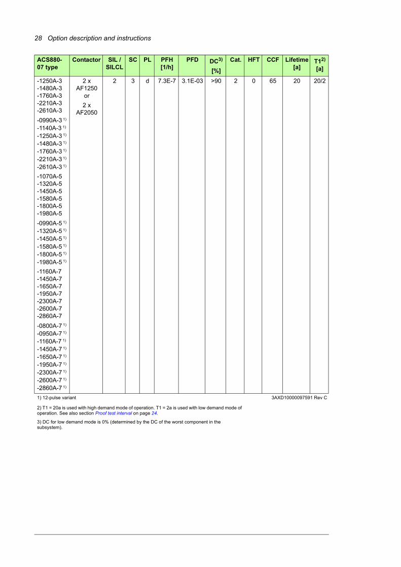
-1250A-3-1480A-3-1760A-3-2210A-3-2610A-3
-0990A-3 1)
-1140A-3 1)
-1250A-3 1)
-1480A-3 1)
-1760A-3 1)
-2210A-3 1)
-2610A-3 1)
-1070A-5-1320A-5-1450A-5-1580A-5-1800A-5-1980A-5
-0990A-5 1)
-1320A-5 1)
-1450A-5 1)
-1580A-5 1)
-1800A-5 1)
-1980A-5 1)
-1160A-7-1450A-7-1650A-7-1950A-7-2300A-7-2600A-7-2860A-7
-0800A-7 1)
-0950A-7 1)
-1160A-7 1)
-1450A-7 1)
-1650A-7 1)
-1950A-7 1)
-2300A-7 1)
-2600A-7 1)
-2860A-7 1)
2 x AF1250
or
2 x AF2050
2 3 d 7.3E-7 3.1E-03 >90 2 0 65 20 20/2
1) 12-pulse variant 3AXD10000097591 Rev C
2) T1 = 20a is used with high demand mode of operation. T1 = 2a is used with low demand mode of operation. See also section Proof test interval on page 24.
3) DC for low demand mode is 0% (determined by the DC of the worst component in the subsystem).
ACS880-07 type
Contactor SIL / SILCL
SC PL PFH[1/h]
PFD DC3)
[%]
Cat. HFT CCF Lifetime[a]
T12)
[a]
Option description and instructions 29
ACS880-17/37 drives with a main contactor
ACS880-07/17/37 drives with a main circuit breaker
Safety component types
Safety component types as defined in IEC 61508-2:• emergency stop button: type A
• safety relays: type A
• contactor(s), circuit breaker: type A.
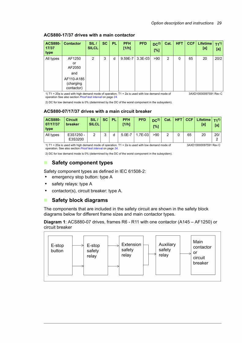
Safety block diagrams
The components that are included in the safety circuit are shown in the safety block diagrams below for different frame sizes and main contactor types.
Diagram 1: ACS880-07 drives, frames R6 - R11 with one contactor (A145 – AF1250) or circuit breaker
ACS880-17/37 type
Contactor SIL / SILCL
SC PL PFH[1/h]
PFD DC2)
[%]
Cat. HFT CCF Lifetime[a]
T11)
[a]
All types AF1250 or
AF2050
and
AF110-A185 (charging contactor)
2 3 d 9.59E-7 3.3E-03 >90 2 0 65 20 20/2
1) T1 = 20a is used with high demand mode of operation. T1 = 2a is used with low demand mode of operation See also section Proof test interval on page 24.
3AXD10000097591 Rev C
2) DC for low demand mode is 0% (determined by the DC of the worst component in the subsystem).
ACS880-07/17/37 type
Circuit breaker
SIL / SILCL
SC PL PFH[1/h]
PFD DC2)
[%]
Cat. HFT CCF Lifetime[a]
T11)
[a]
All types E3S1250 -E3S3200
2 3 d 5.0E-7 1.7E-03 >90 2 0 65 20 20/2
1) T1 = 20a is used with high demand mode of operation. T1 = 2a is used with low demand mode of operation. See also section Proof test interval on page 24.
3AXD10000097591 Rev C
2) DC for low demand mode is 0% (determined by the DC of the worst component in the subsystem).
E-stop button
E-stop safety relay
Extension safetyrelay
Auxiliary safety relay
Main contactor or circuit breaker

30 Option description and instructions
Diagram 2: ACS880-07 drives, frames n x R8i with one contactor (AF1250 – AF2050)
Diagram 3: ACS880-07 drives, frames n x R8i, 12-pulse variants with two contactors (2 x AF2050)
Diagram 4: ACS880-17/37 drives
E-stop button
E-stop safety relay
Auxiliary safety relay
Main contactor
E-stop button
E-stop safety relay
Main contactor
Auxiliary safety relay
Main contactor
Charging contactor
E-stop button
E-stop safety relay
Auxiliary safety relay
Auxiliary safety relay
Main contactor or circuit breaker
Option description and instructions 31
Relevant failure modes
• The main contactor does not open when requested. (All contactor failures are considered dangerous.)
• Internal failures of safety relays and the emergency stop button. These failures are included in the PFH value of the function.
Fault exclusions
Fault exclusions (not considered in the calculations):• any short and open circuits in the cables of the safety circuit
• any short and open circuits in the cabinet terminal blocks of the safety circuits.
Operation delays
Emergency stop total delay: Emergency stop deceleration ramp time + 250 ms

32 Option description and instructions
General rules, notes and definitions
Validation of the safety functions
You must do an acceptance test (validation) to validate the correct operation of safety functions.
Authorized person
An authorized person with expertise and knowledge of the safety function must do the acceptance test of the safety function. The authorized person must fill in and sign the test report.
Validation procedure
You must do the acceptance test using the checklist given in section Start-up and acceptance test on page 21:• at initial start-up of the safety function
• after any changes related to the safety function (wiring, components, safety function related parameter settings etc.)
• after any maintenance action related to the safety function.
The acceptance test must include at least the following steps:• you must have an acceptance test plan
• you must test all commissioned functions for proper operation, from each operation location
• you must document all acceptance tests.
Acceptance test reports
You must store the signed acceptance test reports in the logbook of the machine. The report must include, as required by the referred standards:• a description of the safety application (including a figure)
• a description and revisions of safety components that are used in the safety application
• a list of all safety functions that are used in the safety application
• a list of all safety related parameters and their values
• documentation of start-up activities, references to failure reports and resolution of failures
• the test results for each safety function, checksums, date of the tests and confirmation by the test personnel.
You must store any new acceptance test reports performed due to changes or maintenance in the logbook of the machine.
Competence
The acceptance test of the safety function must be carried out by a competent person with adequate expertise and knowledge of the safety function as well as functional safety, as required by IEC 61508-1 clause 6. The test procedures and report must be documented and signed by this person.
Option description and instructions 33
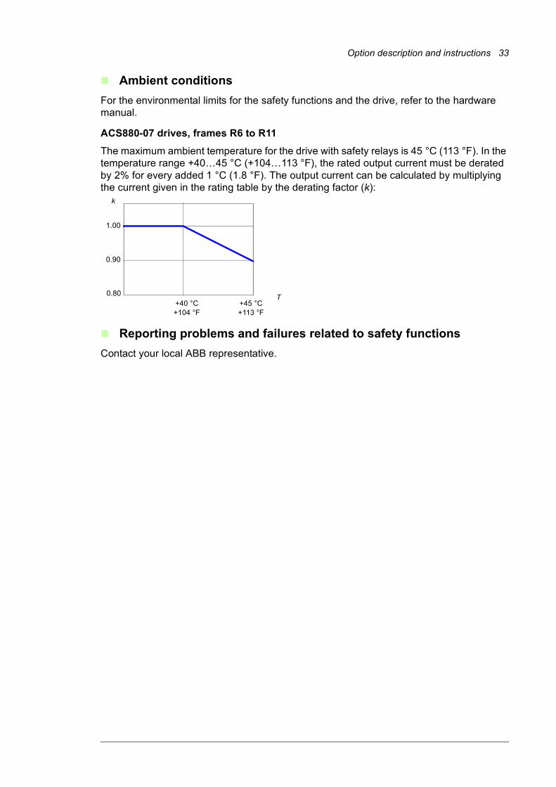
Ambient conditions
For the environmental limits for the safety functions and the drive, refer to the hardware manual.
ACS880-07 drives, frames R6 to R11
The maximum ambient temperature for the drive with safety relays is 45 °C (113 °F). In the temperature range +40…45 °C (+104…113 °F), the rated output current must be derated by 2% for every added 1 °C (1.8 °F). The output current can be calculated by multiplying the current given in the rating table by the derating factor (k):
Reporting problems and failures related to safety functions
Contact your local ABB representative.
T
1.00
0.90
+40 °C+104 °F
+45 °C+113 °F
k
0.80

34 Option description and instructions
Related standards and directives
Compliance with the European Machinery Directive
The drive is an electronic product which is covered by the European Low Voltage Directive. However, the drive internal safety function of this manual (option +Q952) is in the scope of the Machinery Directive as a safety component. This function complies with European harmonized standards such as EN/IEC 61800-5-2. The declaration of conformity is delivered with the drive.
Standard Name
EN 60204-1:2006 + AC:2010IEC 60204-1:2005 + A1:2008
Safety of machinery – Electrical equipment of machines – Part 1: General requirements
IEC 61508:2010 Functional safety of electrical/electronic/programmable electronic safety-related systems. Contains all parts 1…7 of IEC 61508.
EN/IEC 61800-5-2:2007 Adjustable speed electrical power drive systems – Part 5-2: Safety requirements – Functional
EN/IEC 62061:2005 + A1:2013
Safety of machinery – Functional safety of safety-related electrical, electronic and programmable electronic control systems
EN ISO 12100:2010 Safety of machinery – General principles for design – Risk assessment and risk reduction
EN ISO 13849-1:2008 + AC:2009ISO 13849-1:2006
Safety of machinery – Safety-related parts of control systems – Part 1: General principles for design
EN ISO 13849-2:2012 Safety of machinery – Safety-related parts of control systems – Part 2: Validation
EN ISO 13850:2008ISO 13850:2006
Safety of machinery. Emergency stop. Principles for design
IEC 61511:2003 Functional safety – Safety instrumented systems for the process industry sector
IEC 61326-3-1: 2008 Electrical equipment for measurement, control and laboratory use – EMC requirements – Part 3-1: Immunity requirements for safety-related systems and for equipment intended to perform safety-related functions (functional safety) – General industrial applications
2006/42/EC European Machinery Directive
Other Machine-specific C-type standards

Further information
Product and service inquiries
Address any inquiries about the product to your local ABB representative, quoting the type designation and serial number of the unit in question. A listing of ABB sales, support and service contacts can be found by navigating to www.abb.com/searchchannels.
Product training
For information on ABB product training, navigate to new.abb.com/service/training.
Providing feedback on ABB Drives manuals
Your comments on our manuals are welcome. Navigate to new.abb.com/drives/manuals-feedback-form.
Document library on the Internet
You can find manuals and other product documents in PDF format on the Internet at www.abb.com/drives/documents.

Contact us
www.abb.com/driveswww.abb.com/drivespartners
3AUA0000119896 Rev E (EN) 2016-01-15