en - cdn.sick.com
TRANSCRIPT

EN
IOLG2EC-03208R01 – EtherCAT®
IO-Link Master
O P E R AT I N G I N S T R U C T I O N S

Operating instructions IO-Link Master IOLG2EC-03208R01 – EtherCAT®
2 © SICK AG • Presence Detection • Subject to change without notice • 8018499.YV31
Copyright protection!
This work is protected by copyright. The associated rights are reserved by SICK AG. Reproduction of this document is only permissible within the limits of the legal determination of copyright law. Al-teration or abridgment of the document is not permitted without the explicit written approval of SICK AG.

© SICK AG • Presence Detection • Subject to change without notice • 8018499.YV31 3
Operating instructions IO-Link Master IOLG2EC-03208R01 – EtherCAT®
Contents
Contents1 General information ........................................................................... 7
1.1 Information on the operating instructions ................................7
1.2 Explanation of symbols ..............................................................7
1.3 Registered trademark .................................................................7
1.4 Abbreviations ..............................................................................8
1.5 Limitation of liability ...................................................................8
1.6 Scope of delivery.........................................................................9
1.7 Customer service ........................................................................9
1.8 EU declaration of conformity ......................................................9
2 Safety ................................................................................................ 10
2.1 Correct use ............................................................................... 10
2.2 Incorrect use ............................................................................ 10
2.3 Requirementsforqualifiedpersonnel .................................... 11
3 Setup and function .......................................................................... 12
3.1 Setup ........................................................................................ 12
3.2 Function .................................................................................... 13
3.3 Status indicators and operating elements ............................. 13
4 Mounting .......................................................................................... 16
4.1 Mounting the IO-Link Master .................................................. 16
5 Electrical connection ....................................................................... 16
5.1 Safety ........................................................................................ 16
5.2 IO-Link Master electrical connection ...................................... 17
5.3 Connection diagrams .............................................................. 18
5.3.1 Connection diagram for “POWER OUT” and “POWER IN” supply voltage ....... 18
5.3.2 “EtherCAT®” connection diagram .............................. 19
5.3.3 “IO-Link port” connection diagram ........................... 19
6 Systemintegrationandconfiguration............................................ 20
6.1 EtherCAT® and project planning .............................................. 20
6.2 ConfiguringtheIO-LinkMasterusing project planning software and integrating it into the system ........................................... 20
6.3 ConfiguringtheIO-LinkMaster ............................................... 24
6.3.1 Bit mapping and functions of the modules .............. 26
6.4 Startup ...................................................................................... 28

Operating instructions IO-Link Master IOLG2EC-03208R01 – EtherCAT®
Contents
4 © SICK AG • Presence Detection • Subject to change without notice • 8018499.YV31
6.5 Object directory ........................................................................ 30
6.5.1 Input process data (pin 2) Ch. x (0x2000 – 0x2FFF) ........................................... 30
6.5.2 Input process data (pin 4) Ch. x (0x2000 – 0x2FFF) ........................................... 31
6.5.3 AdditionalIO-Linkconfigurationdata(pin4) Ch. x (0x2000 – 0x2FFF) ........................................... 31
6.5.4 AdditionalIOconfigurationdata(pin2) Ch. x (0x2000 – 0x2FFF) ........................................... 31
6.5.5 Display LEDs (0x2A01) .............................................. 31
6.5.6 Module status (0x2A02) ............................................ 32
6.5.7 Output process data Ch. x (0x3000 – 0x3FFF) ........ 32
6.5.8 IO-Link service data Ch. x (0x4000 – 0x4FFF) ......... 32
6.5.9 IO-Linkconfigurationdata Ch. x (0x8000 – 0x8FFF) ........................................... 32
6.5.10 IO-Link information data Ch. x (0x9000 – 0x9FFF) ........................................... 33
6.5.11 IO-Link diagnosis data Ch. x (0xA000 – 0xAFFF) ..... 33
6.5.12 IO-Link status data Ch. x (0xF100) ........................... 33
7 Operation on the IO-Link Master .................................................... 34
7.1 Status indicators and operating buttons ............................... 34
7.1.1 Operating buttons ...................................................... 34
7.1.2 ConfiguringdisplayLEDs ........................................... 34
7.2 Modes and displays ................................................................. 35
7.2.1 Operating mode .......................................................... 35
7.2.2 Display mode .............................................................. 35
7.3 Commissioning ........................................................................ 35
7.4 Main menu ............................................................................... 36
7.5 “NETWORK CONFIG” menu ..................................................... 36
7.6 “MODULE INFO” menu – information about the IO-Link Master .................................... 36
8 Operation via the web server .......................................................... 37
8.1 General information ................................................................. 37
8.2 Configuringaccesstothewebserver ..................................... 37
8.3 Views ......................................................................................... 37
9 Cleaning and maintenance ............................................................. 44
10 Disposal ............................................................................................ 44

© SICK AG • Presence Detection • Subject to change without notice • 8018499.YV31 5
Operating instructions IO-Link Master IOLG2EC-03208R01 – EtherCAT®
Contents
11 Technical data .................................................................................. 45
11.1 Dimensions .............................................................................. 45
11.2 Supply ....................................................................................... 46
11.3 EtherCAT® .................................................................................................................................................46
11.4 Ambient conditions .................................................................. 46
11.5 Structural design...................................................................... 47
Index .......................................................................................................... 49

Operating instructions IO-Link Master IOLG2EC-03208R01 – EtherCAT®
6 © SICK AG • Presence Detection • Subject to change without notice • 8018499.YV31

© SICK AG • Presence Detection • Subject to change without notice • 8018499.YV31 7
Operating instructions IO-Link Master IOLG2EC-03208R01 – EtherCAT®
General information
1 General information
1.1 Information on the operating instructions
These operating instructions supplement the supplied QuickStart guide and include additional information and more detailed descriptions of work-ing with the IOLG2EC-03208R01 EtherCAT® IO-Link Master.
Theseoperatinginstructionsareintendedforqualifiedpersonnelandelec-trical specialists and must be read before starting any work.
1.2 Explanation of symbols
Physical damage Warnings in these operating instructions are labeled with symbols.
These warnings must be observed at all times and care must be taken to avoid physical damage.
WARNING!
… indicates a possible hazardous situation which may lead to physical damage if it is not avoided.
Tips and recommendationsNOTE!
… highlights useful tips and recommendations as well as information for efficient and trouble-free operation.
1.3 Registered trademark
EtherCAT®
EtherCAT® is a registered trademark and patented technology licensed by Beckhoff Automation GmbH, Germany

Operating instructions IO-Link Master IOLG2EC-03208R01 – EtherCAT®
General information
8 © SICK AG • Presence Detection • Subject to change without notice • 8018499.YV31
1.4 Abbreviations
Abbreviation Description
DID Device ID
ECT EtherCAT®
EMC Electromagnetic compatibility
FE Functional grounding
I Standard input port
O Standard output port
VID Vendor ID
Table 1: Abbreviations
1.5 Limitation of liability
Applicable standards and regulations, the latest state of technological development, and many years of knowledge and experience have all been taken into account when assembling the data and information contained in these operating instructions.
The manufacturer accepts no liability for damage caused by:
• Failing to observe the operating instructions
• Incorrect use
• Use by untrained personnel
• Opening the housing
• Unauthorized conversions
• Technicalmodifications
• Use of defective devices
• Use of unauthorized spare parts/consumable parts.
With special variants, where optional extras have been ordered, or owing to the latest technical changes, the actual scope of delivery may vary from the features and illustrations shown here.
© SICK AG • Presence Detection • Subject to change without notice • 8018499.YV31 9
Operating instructions IO-Link Master IOLG2EC-03208R01 – EtherCAT®
General information
1.6 Scope of delivery
Included with delivery:
• EtherCAT® IO-Link Master IOLG2EC-03208R01
• 4 M12 blind plugs for sealing unused IO-Link ports
• M4 ground strap with M4 x 6 screw
• 20 labels
Supplied documentation:
• QuickStart
1.7 Customer service
If you require any technical information, our customer service department will be happy to help.
Seethebackpageforyourrepresentativeoffice.
NOTE!
In order to allow us to deal with the matter quickly, please note down the type designation and order number before calling. This information can be found on the side of the IO-Link Master.
1.8 EU declaration of conformity
→ You can download the EU declaration of conformity via the Internet from “www.sick.com”.

Operating instructions IO-Link Master IOLG2EC-03208R01 – EtherCAT®
Safety
10 © SICK AG • Presence Detection • Subject to change without notice • 8018499.YV31
2 Safety
2.1 Correct use
The IOLG2EC-03208R01 IO-Link Master is a remote IO-Link input and out-put module for integration into an EtherCAT® network.
The IOLG2EC-03208R01 IO-Link Master may only be used in applications in which the safety of personnel does not depend on the device function.
SICK AG assumes no liability for losses or damage arising from the use of the product, either directly or indirectly. This applies in particular to use of the product that does not conform to its intended purpose and is neither described nor mentioned in this documentation.
2.2 Incorrect use
The IOLG2EC-03208R01 IO-Link Master must not be used in explosive environments.
Any other use that is not described as a correct use is prohibited.
No accessories may be connected which have not been explicitly stipulat-ed, in terms of quantity and properties, and approved by SICK AG.

© SICK AG • Presence Detection • Subject to change without notice • 8018499.YV31 11
Operating instructions IO-Link Master IOLG2EC-03208R01 – EtherCAT®
Safety
2.3 Requirements for qualifiedpersonnel
WARNING!
Damage to the device in the event of improper han-dling!
Improper handling may lead to physical damage.
For this reason:
• All work must only ever be carried out by the stipulated persons.
Theoperatinginstructionsstatethefollowingqualificationrequirementsforthe various areas of work:
• Qualified personnel are able to carry out the work assigned to them and independently recognize potential risks due to their specialist training, knowledge, and experience, as well as knowledge of the relevant regulations.
• Electrical specialists are able to carry out work on electrical systems and independently recognize potential risks due to their specialist training, knowledge, and experience, as well as knowledge of the relevant standards and regula-tions. InGermany,electricalspecialistsmustmeetthespecificationsoftheBGV A3 Work Safety Regulations (e.g., Master Electrician). Other relevant regulations applicable in other countries must be observed.

Operating instructions IO-Link Master IOLG2EC-03208R01 – EtherCAT®
Setup and function
12 © SICK AG • Presence Detection • Subject to change without notice • 8018499.YV31
3 Setup and function
3.1 Setup
US UA RUN ERR 100 L/A1 100 L/A2
0 1
0 10 1
0 1
0 1
0 1
0 1
0 1
0 1
0 1
2 3
4 5
6 7
LK1IN
LK2OUT
POWEROUT
POWERIN
255P
S ↑
2
1
3
4
5
6
7
8
9
ß
ç
æ
å
ä
ã
â
á
à
Fig. 1: EtherCAT® IO-Link Master setup IOLG2EC-03208R011 Functional grounding connection
2 EtherCAT® port 1 IN
3 Display with operating buttons and two display LEDs
4 Output supply voltage
5 Status LED: IO-Link Master/ Ethernet communication
6 Port 0 (IO-Link, standard I/O)
7 Port 2 (IO-Link, standard I/O)
8 Port 4 (IO-Link, standard I/O)
9 Port 6 (IO-Link, standard I/O)
ß Mounting hole
à EtherCAT® port 2 OUT
á Label
â Input supply voltage
ã Port 1 (IO-Link, standard I/O)
ä Pin/port LEDs: Signal status
å Port 3 (IO-Link, standard I/O)
æ Port 5 (IO-Link, standard I/O)
ç Port 7 (IO-Link, standard I/O)

© SICK AG • Presence Detection • Subject to change without notice • 8018499.YV31 13
Operating instructions IO-Link Master IOLG2EC-03208R01 – EtherCAT®
Setup and function
3.2 Function
The IOLG2EC-03208R01 IO-Link Master is a remote IO-Link input and out-put module for integration into an EtherCAT® network.
Theeightportscanbeconfiguredandusedindependentlyofoneanother.TheycaneitherbeconfiguredasIO-LinkportsorstandardI/Oports.
TheIO-LinkMasterisintegratedandconfiguredusingprojectplanningsoft-ware. It can also be operated via the display or the web server.
3.3 Status indicators and operating elements
255P
S ↑
��
�
��
Fig. 2: Status indicators and operating buttons
1 Display LED (configurable)
2 Arrow pushbutton
3 Display
4 Set pushbutton
5 Display LED (configurable)
Pushbuttons Pushbutton Description
↑ • Select menu.• Scroll through the menu.
S • Scroll through the main menu.
Table 2: Pushbuttons

Operating instructions IO-Link Master IOLG2EC-03208R01 – EtherCAT®
Setup and function
14 © SICK AG • Presence Detection • Subject to change without notice • 8018499.YV31
Function indicators (LEDs)
US UA RUN ERR 100 L/A1 100 L/A2
0 1 0 1
0 11
2
Fig. 3: Function indicators (LEDs)
1 Status LEDs: IO-Link Master/communication
2 Pin/port LEDs: Signal status
Pin/port LEDs: Pin 2 and pin 4 assignment
Portconfiguredas Right LED Left LED
IO-Link port Pin 4 signal status Pin 2 signal status
Standard I/O port Pin 2 signal status Pin 4 signal status
Table 3: Pin/port LEDs: Assignment
Status LEDs: IO-Link Master Function indicator Description
US • LED lights up green: Sensor supply OK.• LEDflashesred:Sensorsupply<18V
UA • LED lights up green: Actuator voltage OK.• LEDflashesred:Actuatorvoltage<18V• LED lights up red: No actuator voltage
RUN Current status of the IO-Link Master• LED off: INIT• LEDflashesgreen:PRE-OPERATIONAL.• LEDsingleflashinggreen:SAFE-OPERATIONAL• LED lights up green: OPERATIONAL
ERR • LED off: No error• LEDflashesred:Invalidconfiguration• LEDsingleflashingred:Localerror• LEDdoubleflashingred:Applicationwatchdogtime
exceeded• LED red: Error in the application
Table 4: Status LEDs: IO-Link Master
Status LEDs: Communication
Function indicator Description
100 • LED off: Transfer rate 10 Mbit/s• LED lights up yellow: Transfer rate 100 Mbit/s
L/A1 and L/A2 • LED green: Data transfer
Table 5: Status LEDs: Communication

© SICK AG • Presence Detection • Subject to change without notice • 8018499.YV31 15
Operating instructions IO-Link Master IOLG2EC-03208R01 – EtherCAT®
Setup and function
Pin/port LEDs: Standard I/O port LED display Description
Off The I/O status of the relevant input or output pin is “0”
Yellow The I/O status of the relevant input or output pin is “1”
Flashing red Short-circuit in sensor supply between pin 1 and pin 3
Red Short-circuit on relevant output, either between pin 2 and pin 3 and/or between pin 4 and pin 3
Table 6: Pin/port LEDs: Standard I/O port
Pin/port LEDs: IO-Link port LED display Description
Green IO-Link connection active
Flashing green No IO-Link connection
Green,fastflashing IO-Link preoperate during data storage
Red,fastflashing • Validation failed• IncorrectconfigurationofIO-Linkdatalength• Data storage failed• Incorrect device for data storage
Red IO-Link short-circuit between pin 3 and pin 4
Table 7: Pin/port LEDs: IO-Link port

Operating instructions IO-Link Master IOLG2EC-03208R01 – EtherCAT®
Mounting
16 © SICK AG • Presence Detection • Subject to change without notice • 8018499.YV31
4 Mounting
4.1 Mounting the IO-Link Master
> Mount the IO-Link Master using the 2 mounting holes with M6 screws and washers.
5 Electrical connection
5.1 Safety
Electromagnetic interferenceWARNING!
Electromagnetic interference!
Electromagnetic interference can cause the device, sys-tem, or nearby devices to malfunction! The IO-Link Master meets the requirements of Class A (industrial applica-tions). Operation in other electromagnetic environments may cause faults or malfunctions.
• The operator must take appropriate precautions.
• Only connect the IO-Link Master to approved voltage supplies.
• Only use approved cables.
Working with live partsWARNING!
Equipment damage due to working with live parts!
Working with live parts may result in damage to the equipment.
• Only connect and disconnect cable connections when the power is off.
Incorrect supply voltageWARNING!
Equipment damage due to incorrect supply voltage!
An incorrect supply voltage may result in damage to the equipment.
• Protect the supply voltage with max. 8 A fuses.

© SICK AG • Presence Detection • Subject to change without notice • 8018499.YV31 17
Operating instructions IO-Link Master IOLG2EC-03208R01 – EtherCAT®
Electrical connection
Excessive current loadWARNING!
Equipment damage due to excessive current load!
An excessive current load may result in damage to the equipment.
• Do not exceed the maximum permissible total current of 8 A for the IO-Link Master.
• Each output provides a maximum current of 2 A.
• The sensors/bus and the actuator should be powered via separate current sources if possible.
Incorrect functional groundingWARNING!
Incorrect functional grounding!
An incorrect functional grounding may result in equip-ment damage or malfunction.
• The grounding between the IO-Link Master and the machine must be a low-impedance system.
• The ground connection must be as short as possible.
5.2 IO-Link Master electrical connection
1. Ensure power supply is not connected.
2. Connect the IO-Link Master to the functional grounding of the system usingthesuppliedgroundstrap.Seefollowingfigure.
3. Connect supply voltage to “POWER IN” using a suitable cable.
4. ConnectfieldbusconnectionviaLK1/LK2.
5. Connect IO-Link devices or standard devices to the IO-Link ports.
6. If provided, connect the next gateway to “POWER OUT”.
Functional grounding
Fig. 4: Ground connection

Operating instructions IO-Link Master IOLG2EC-03208R01 – EtherCAT®
Electrical connection
18 © SICK AG • Presence Detection • Subject to change without notice • 8018499.YV31
7. IO-Link ports that are not in use must be sealed with M12 blind plugs to ensure the enclosure rating of IP 67.
NOTE!
Four M12 blind plugs are included in the scope of delivery.
5.3 Connection diagrams
5.3.1 Connection diagram for “POWER OUT” and “POWER IN” supply voltage
NOTE!
Note the pin assignment of the used connecting cables.
51
3
2 4
15
3
4 2
Fig. 5: Supply voltage Left: Output “POWER OUT” 7/8” female connector, 5-pin Right: Input “POWER IN” 7/8” male connector, 5-pin
Contact Signal Description
1 0 V GND actuator supply
2 0 V GND IO-Link Master and/or sensor supply
3 FE Functional grounding
4 24 V DC IO-Link Master and/or sensor supply
5 24 V DC Actuator supply
Table 8: Description of “POWER OUT” and “POWER IN” supply voltage

© SICK AG • Presence Detection • Subject to change without notice • 8018499.YV31 19
Operating instructions IO-Link Master IOLG2EC-03208R01 – EtherCAT®
Electrical connection
5.3.2 “EtherCAT®” connection diagram
3
4
1
2
Fig. 6: EtherCAT® connection diagram, M12 female connector, D-coded, 4-pin
Contact Signal Description
1 Tx+ Sender+
2 Rx+ Receiver+
3 Tx– Sender–
4 Rx– Receiver–
Table 9: EtherCAT® description, M12 female connector, D-coded, 4-pin
5.3.3 “IO-Link port” connection diagram
35
4
1
2
Fig. 7: IO-Link port connection diagram, M12 female connector, A-coded, 5-pin
Port used as I/O port Contact Signal Description
1 L+ 24 V DC, 1.6 A
2 I/O Input or output (max. 2 A)
3 M GND
4 IO-Link Input or output (max. 2 A)
5 Not connected Not connected
Table 10: IO-Link port description, M12 female connector, A-coded, 5-pin
Port used as IO-Link port Contact Signal Description
1 L+ 24 V DC, 1.6 A
2 I/O Input or output (max. 2 A)
3 M GND
4 IO-Link IO-Link
5 Not connected Not connected
Table 11: IO-Link port description, M12 female connector, A-coded, 5-pin
For the digital sensor inputs, see EN 61131-2, type 2.

Operating instructions IO-Link Master IOLG2EC-03208R01 – EtherCAT®
Systemintegrationandconfiguration
20 © SICK AG • Presence Detection • Subject to change without notice • 8018499.YV31
6 Systemintegrationandconfiguration
6.1 EtherCAT® and project planning
Components Communication between the IO-Link Master and the controlling system takes place via EtherCAT®.
The system consists of the following components:
• Bus master
• Bus modules (slave) such as the IO-Link Master.
The IO-Link Master is mapped as a modular device in the project planning software. The data modules of the inputs/outputs, the IO-Link ports, and any additional modules are presented in the project planning software on the basis of slots. Slots that are not in use can be left empty.
ThedevicedatarequiredforprojectplanningisstoredintheESIfiles.TheESIfilesprovidethepossibledatamodules,suchasinputs/outputs,IO-Link ports with a different data width, and other additional modules. Thesefilesareusedtoconfigurethebusmasterinamannerappropriateto its type.
6.2 ConfiguringtheIO-LinkMasterusingprojectplanningsoftware and integrating it into the system
Theconfigurationandsystemintegrationaredescribedusinganexamplein which the IO-Link Master is connected to a Beckhoff TwinCAT controller with the “TwinCAT® System Manager (Version 2)”.
When using other controllers and project planning software, refer to the relevant documentation.
1. DownloadtheESIfilesfrom“www.sick.com”.
2. CopytheESIfilesintothe“TwinCAT”directory.Defaultpath: C:\TwinCAT\lo\EtherCAT The IO-Link Master will be available the next time the “TwinCAT® System Manager” is started.
3. Make sure that the EtherCAT® system is safe and de-energized.
4. Connect the IO-Link maser to the EtherCAT® network.
5. Switch on the supply voltage.
6. Start the “TwinCAT®SystemManager”in“ConfigMode”.
7. Append the IO-Link Master. You can either append the IO-Link Master manually or you can use automatic scanning.

© SICK AG • Presence Detection • Subject to change without notice • 8018499.YV31 21
Operating instructions IO-Link Master IOLG2EC-03208R01 – EtherCAT®
Systemintegrationandconfiguration
Appending the IO-Link master using automatic scanning
> Execute the “Scan devices” command via the context menu.
Fig. 8: “Scan devices”
Appending the IO-Link Master manually
> Select the “Append box” command via the context menu.
Fig. 9: “Append box”

Operating instructions IO-Link Master IOLG2EC-03208R01 – EtherCAT®
Systemintegrationandconfiguration
22 © SICK AG • Presence Detection • Subject to change without notice • 8018499.YV31
Appending the IO-Link Master manually (continued)
8. Select the IO-Link Master in the “Insert EtherCAT® Device” window. You will see the following screen:
Fig. 10: Insert EtherCAT® Device
9. If the IO-Link Master was appended successfully, the tree structure appears.
Fig. 11: TwinCAT tree structure

© SICK AG • Presence Detection • Subject to change without notice • 8018499.YV31 23
Operating instructions IO-Link Master IOLG2EC-03208R01 – EtherCAT®
Systemintegrationandconfiguration
EoE (Ethernet over Ethercat) 10. The IO-Link Master supports EoE (Ethernet over Ethercat). To use this function, enter a valid DNS name and IP address. “EtherCAT®” tab – Path: Advanced Settings > Mailbox > EoE
Fig. 12: Insert EtherCAT® Device
Fig. 13: Activate and deactivate EoE function
NOTE!
The “EoE” function is activated by default. The function is deactivated using the “Virtual Ethernet Port” check box.

Operating instructions IO-Link Master IOLG2EC-03208R01 – EtherCAT®
Systemintegrationandconfiguration
24 © SICK AG • Presence Detection • Subject to change without notice • 8018499.YV31
Station alias The station alias is used for the EtherCAT function “Hot Connect”.
11. Enter a value for “Station Alias”. The new value will only apply after a reset. “EtherCAT®” tab – Path: Advanced Settings > ESC Access > E2PROM > ConfiguredStationAlias
Fig. 14: Setting a station alias
6.3 ConfiguringtheIO-LinkMaster
Slot structure of the IO-Link Master
The IO-Link Master is a modular device with the following slot structure:
Slot number Description
1 to 8 IO-Link ports
9 to 16 Unused slots, reserved for future extensions
17 Input pin 2
18 Short-circuit pin 2
19 Short-circuit pin 4
20 Sensor short-circuit
21 IO-Link state (module status)
22 to 32 Unused slots, reserved for future extensions
33 Output pin 2
34 Restart pin 2
35 Restart pin 4
36 Display LEDs
Table 12: Slot structure of the IO-Link Master

© SICK AG • Presence Detection • Subject to change without notice • 8018499.YV31 25
Operating instructions IO-Link Master IOLG2EC-03208R01 – EtherCAT®
Systemintegrationandconfiguration
You can assign a certain amount of process data (buffer size) to the slots.
Theconnecteddevicespecifiesthelengthoftheprocessdataataport.Select the right module according to the connected device.
The slots for future extensions are not used.
→Foradetaileddescriptionoftheslots,seepage26,chapter6.3.1.
Fig. 15: “Slots” tab for the IO-Link Master
Fig. 16: Example module configuration

Operating instructions IO-Link Master IOLG2EC-03208R01 – EtherCAT®
Systemintegrationandconfiguration
26 © SICK AG • Presence Detection • Subject to change without notice • 8018499.YV31
6.3.1 Bit mapping and functions of the modules
Inputs pin 4 Inputs pin 2 Outputs pin 4 Outputs pin 2
The slots mentioned in table 12 are described in detail below.
Signalsfromconfiguredinputsandoutputsaremappedinmodulesasfollows:
Module Inputs/outputs
STD_IN_1bit Inputs pin 4
Input pin 2 Inputs pin 2
STD_OUT_1bit Outputs pin 4
Output pin 2 Outputs pin 2
Table 13: Modules for the input and output signals
IO-Link module schema IO-Link modules are structured according to the following schema:
• IOL_I/O_x/xBytes
Description
I/O • I: Input data• O: Output data• I/O: Input and output data
x/xBytes Amount of process data used. The amount should be equal to or greater than the process data length of the IO-Link device.
Table 14: IO-Link module schema
Short-circuit pin 2 or short circuit pin 4
This module indicates whether there is a short-circuit between a set output and ground on a port.
Bit 7 Bit 6 Bit 5 Bit 4 Bit 3 Bit 2 Bit 1 Bit 0
Port 7 Port 6 Port 5 Port 4 Port 3 Port 2 Port 1 Port 0
Restart pin 2 or restart pin 4
Thismoduleenablesyoutoconfigurethestartupbehaviorafteranactua-tor short-circuit.
• Bit set: Automatic restart
• Bit not set: No automatic restart; restart must be triggered manually.
Bit 7 Bit 6 Bit 5 Bit 4 Bit 3 Bit 2 Bit 1 Bit 0
Port 7 Port 6 Port 5 Port 4 Port 3 Port 2 Port 1 Port 0

© SICK AG • Presence Detection • Subject to change without notice • 8018499.YV31 27
Operating instructions IO-Link Master IOLG2EC-03208R01 – EtherCAT®
Systemintegrationandconfiguration
IO-Link state (module status) This module indicates the current status of each port.
Status Description
0x_0 Port disabled
0x_1 Port in std dig in
0x_2 Port in std dig out
0x_3 Port in communication OP
0x_4 Port in communication COMSTOP
0x1_ Watchdog detected
0x2_ Internal error
0x3_ Invalid device ID
0x4_ Invalid vendor ID
0x5_ Invalid IO-Link version
0x6_ Invalid frame capability
0x7_ Invalid cycle time
0x8_ Invalid PD in length
0x9_ Invalid PD out length
0xA_ No device detected
Table 15: “IO-Link state” module
Sensor short-circuit This module indicates whether there is a short-circuit in the sensor supply on a port.
Bit 7 Bit 6 Bit 5 Bit 4 Bit 3 Bit 2 Bit 1 Bit 0
Port 7 Port 6 Port 5 Port 4 Port 3 Port 2 Port 1 Port 0
Display LED This module enables you to control the display LEDs.Bit 7 Bit 6 Bit 5 Bit 4 Bit 3 Bit 2 Bit 1 Bit 0
Green LED
Red LED

Operating instructions IO-Link Master IOLG2EC-03208R01 – EtherCAT®
Systemintegrationandconfiguration
28 © SICK AG • Presence Detection • Subject to change without notice • 8018499.YV31
6.4 Startup
YoucanpreconfiguretheIO-Linkportsandtheoutputsinthe“Startup”tab.You can edit the entry by selecting it and then calling up the context menu. Theentriesaretransferredwhentheconfigurationisoverwritten.
You also have the option of activating the validation for an IO-Link port. This allows you to check whether a particular device is connected.
Fig. 17: “Startup” tab
Fig. 18: Edit entry

© SICK AG • Presence Detection • Subject to change without notice • 8018499.YV31 29
Operating instructions IO-Link Master IOLG2EC-03208R01 – EtherCAT®
Systemintegrationandconfiguration
Validation The following options are available for validation:
Option Description
0 = No validation Validation is deactivated. Every IO-Link device is accepted.
1: Compatibility (VID + DID)
Manufacturer ID and device ID are compared with the module data. IO-Link communication only starts if they match.
2: Identity (VID + DID + SN)
Manufacturer ID, device ID, and serial number are com-pared with the module data. IO-Link communication only starts if they match.
Table 16: Validation
Parameter server The following options are available for the parameter server:
Option Description
0x8X Switch on The data storage functions are active. Parameter data and identificationdataoftheIO-Linkdevicesareresiduallysaved.
0x0X Switch off The data storage functions are deactivated. The saved data is retained.
0x40 Delete The data storage functions are deactivated. The saved data is deleted.
0xX1 Enable or block upload
Enable or block the parameter data upload into the IO-Link Master port data storage.• Enable upload:
The IO-Link Master starts to upload the parameter data as soon as an IO-Link device requests an upload (upload flagset)orifthereisnodatastoredinthemasterport,e.g.,afterthedatahasbeendeletedorbeforethefirstdata upload
• Block upload: The data is not uploaded. If an IO-Link de-vice sends an upload request, a download starts if there are different parameter sets since an upload cannot take place. The download must be enabled.
0xX2 Enable or block download
Enable or block the parameter data download to the IO-Link device.• Enable download: As soon as the saved parameter
data in the parameter server of the port differs from a connected IO-Link device and there is no upload request from the IO-Link device, a download is performed.
• Block download: If the download is blocked, the param-eterdataisuploaded.TheuploadflagfortheIO-Linkdevice does not need to be set in this case. The upload must be enabled.
Block upload and download
If both upload and download are blocked, the parameter data is not exchanged. However, the IO-Link device still communicates with the IO-Link port.
Table 17: Parameter server

Operating instructions IO-Link Master IOLG2EC-03208R01 – EtherCAT®
Systemintegrationandconfiguration
30 © SICK AG • Presence Detection • Subject to change without notice • 8018499.YV31
NOTE!
After the parameter data upload, the vendor ID and de-vice ID are retained until the data sets of the connected IO-Link device are deleted.
A validation takes place when the connected IO-Link de-vice starts up. This means that only one IO-Link device of the same type can be used for data storage. In order to use an IO-Link device of a different type, you must delete the content of the parameter server.
IO-Linkdeviceuploadflag You set the function individually for each port via the object “0x20n2” and “0x20n3”. “n” in this case stands for the relevant port number – 0 to 7. →Seepage31,chapter6.5.3andpage31,chapter6.5.4.
Formoreinformationaboutconfiguration,pleaserefertotheIO-Linkser-vice data on the next page.
Iftheuploadflagisset,datathatisalreadysavedintheparameterservercan be overwritten with new parameter data for the same IO-Link device.
Safe state Thisfunctionisanextensionofanoutputconfigurationoftherelevantportpin.Foreachportpin,youcanpredefineasafestatewhichshouldbeassumed if bus communication is lost.
The following options are possible:
• 0x00: 0
• 0x01: 1
• 0x02: Last state
6.5 Object directory
IO-Linkconfiguration IO-Link ISDU parameters can be read or written from the IO-Link device via the “0x4000 (IO-Link service data Ch. X)” object.
To do this, you must enter the corresponding index and subindex. To write the parameters, you must also enter the corresponding length and the data.
The read or write task is started via the “control object”. The result is dis-played in the “status object”.
6.5.1 Input process data (pin 2) Ch. x (0x2000 – 0x2FFF)
Index Subindex Name Data type Access Description/Value
0x20n0n = 0 … 7
0x01 Input pin 2 BOOLEAN RO –
0x02 Actor short-circuit pin 2 BOOLEAN RO –

© SICK AG • Presence Detection • Subject to change without notice • 8018499.YV31 31
Operating instructions IO-Link Master IOLG2EC-03208R01 – EtherCAT®
Systemintegrationandconfiguration
6.5.2 Input process data (pin 4) Ch. x (0x2000 – 0x2FFF)
Index Subindex Name Data type Access Description/Value
0x20n1n = 0 … 7
0x01 Actor short-circuit pin 4 BOOLEAN RO –
0x02 Sensor supply short-circuit BOOLEAN RO A potential short circuit on a port is indicated as follows:Bit 7: Port 7Bit 6: Port 6Bit 5: Port 5Bit 4: Port 4Bit 3: Port 3Bit 2: Port 2Bit 1: Port 1Bit 0: Port 0
6.5.3 AdditionalIO-Linkconfigurationdata(pin4)Ch.x(0x2000–0x2FFF)
Index Subindex Name Data type Access Description/Value
0x20n2n = 0 … 7
0x01 Safe state UINT8 RW 0x00: 00x01: 10x02: Last state
0x02 Validation type UINT8 RW 0: No validation1: Compatibility (VID + DID)2: Identity (VID + DID + SN)→Seepage29,table16.
0x03 Parameter server UINT8 RW →Seepage29,table17.
6.5.4 AdditionalIOconfigurationdata(pin2)Ch.x(0x2000–0x2FFF)
Index Subindex Name Data type Access Description/Value
0x20n3n = 0 … 7
0x01 Safe state UINT8 RW • 0x00: 0• 0x01: 1• 0x02: Last state
6.5.5 Display LEDs (0x2A01)
Index Subindex Name Data type Access Description/Value
0x2A01 0x01 LED red BOOLEAN RO Bit 1: Green LED
0x02 LED green BOOLEAN RO Bit 0: Red LED

Operating instructions IO-Link Master IOLG2EC-03208R01 – EtherCAT®
Systemintegrationandconfiguration
32 © SICK AG • Presence Detection • Subject to change without notice • 8018499.YV31
6.5.6 Module status (0x2A02)
Index Subindex Name Data type Access Description/Value
0x2A02 0x01 UA low BOOLEAN RO –
0x02 US low BOOLEAN RO –
0x03 no UA BOOLEAN RO –
6.5.7 Output process data Ch. x (0x3000 – 0x3FFF)
Index Subindex Name Data type Access Description/Value
0x30n0 0x01 Output pin 2 BOOLEAN RO –
0x02 Restart pin 2 BOOLEAN RO –
0x30n1n = 0 … 7
0x01 Restart pin 4 BOOLEAN RO –
6.5.8 IO-Link service data Ch. x (0x4000 – 0x4FFF)
Index Subindex Name Data type Access Description/Value
0x40n0n = 0 … 7
0x01 Control UINT8 RW • 0: no control action• 3: read• 2: write
0x02 Status UINT8 RO • 0: no activity• 1: busy• 2: success• 4: error• 0xFF: failure
0x03 Index UINT16 RW –
0x04 Subindex UINT8 RW –
0x05 Length UINT8 RW –
0x06 Data UINT232 RW –
0x07 Error code UINT16 RO –
6.5.9 IO-LinkconfigurationdataCh.x(0x8000–0x8FFF)
Index Subindex Name Data type Access Description/Value
0x80n0n = 0 … 7
0x04 Device ID UINT32 RW –
0x05 Vendor ID UINT32 RW –
0x06 Product ID UINT32 RW –
0x08 Serial number UINT32 RW –
0x20 IO-Link revision UINT8 RW –
0x21 Frame capability UINT8 RW –
0x22 Min cycle time UINT8 RW –
0x24 Process data in length UINT8 RW –
0x25 Process data out length UINT8 RW –
0x28 Master control UINT16 RW –

© SICK AG • Presence Detection • Subject to change without notice • 8018499.YV31 33
Operating instructions IO-Link Master IOLG2EC-03208R01 – EtherCAT®
Systemintegrationandconfiguration
6.5.10 IO-Link information data Ch. x (0x9000 – 0x9FFF)
Index Subindex Name Data type Access Description/Value
0x90n0n = 0 … 7
0x04 Device ID UINT32 RO –
0x05 Vendor ID UINT32 RO –
0x06 Product ID UINT32 RO –
0x08 Serial number UINT32 RO –
0x20 IO-Link revision UINT8 RO –
0x21 Frame capability UINT8 RO –
0x22 Min cycle time UINT8 RO –
0x24 Process data in length UINT8 RO –
0x25 Process data out length UINT8 RO –
6.5.11 IO-Link diagnosis data Ch. x (0xA000 – 0xAFFF)
Index Subindex Name Data type Access Description/Value
0xA0n0n = 0 … 7
0x01 IO-Link state UINT8 RO –
0x02 Lost frames UINT8 RO –
6.5.12 IO-Link status data Ch. x (0xF100)
Index Subindex Name Data type Access Description/Value
0xF100 0x01 IO-Link state port 0 UINT8 RO –
0x02 IO-Link state port 1 UINT8 RO –
0x03 IO-Link state port 2 UINT8 RO –
0x04 IO-Link state port 3 UINT8 RO –
0x05 IO-Link state port 4 UINT8 RO –
0x06 IO-Link state port 5 UINT8 RO –
0x07 IO-Link state port 6 UINT8 RO –
0x08 IO-Link state port 7 UINT8 RO –

Operating instructions IO-Link Master IOLG2EC-03208R01 – EtherCAT®
Operation on the IO-Link Master
34 © SICK AG • Presence Detection • Subject to change without notice • 8018499.YV31
7 Operation on the IO-Link Master
You can use the display on the IO-Link Master to call up the following infor-mation:
• Station alias
• Hardwareandfirmwareversion.
7.1 Status indicators and operating buttons
Overview
255P
S ↑
��
�
��
Fig. 19: Status indicators and operating buttons
1 Display LED (configurable)
2 Arrow pushbutton
3 Display
4 Set pushbutton
5 Display LED (configurable)
7.1.1 Operating buttons
Functions Pushbutton Description
↑“Arrow” pushbutton
• Select menu.• Scroll through the menu.
S“Set” pushbutton
• Scrollthroughthemainmenu:Presspushbuttonbriefly.
Table 18: Functions of the operating buttons
7.1.2 ConfiguringdisplayLEDs
ThedisplayLEDsareconfiguredviathe“DisplayLED”function. → See “Display LED” on page 27.

© SICK AG • Presence Detection • Subject to change without notice • 8018499.YV31 35
Operating instructions IO-Link Master IOLG2EC-03208R01 – EtherCAT®
Operation on the IO-Link Master
7.2 Modes and displays
7.2.1 Operating mode
The IO-Link Master is in operation when in operating mode. The display shows the station alias.
7.2.2 Display mode
Display mode allows you to call up information.
If no pushbuttons are pressed for 10 seconds, the display returns to oper-ating mode.
7.3 Commissioning
SICK
IOLG2EC-03208R01
VERSIONHW : 1 . 0SW : 1 . 0
STATIONALIAS 1001
�
�
�
�
Fig. 20: Commissioning
1 SICK
2 IO-Link Master device designation
3 Current hardware and firmware
4 Current station alias

Operating instructions IO-Link Master IOLG2EC-03208R01 – EtherCAT®
Operation on the IO-Link Master
36 © SICK AG • Presence Detection • Subject to change without notice • 8018499.YV31
7.4 Main menu
Main menu
S
NETWORKCONFIG
MODULINFO
S
↑
S
�
�
� ↑
S
STATIONALIAS 1001
STATIONALIAS 1001
IOLG2EC-03208R01
S
Fig. 21: Main menu
1 Status indicator: Station alias
2 Menu for network configuration
3 Menu for displaying information about the IO-Link Master
7.5 “NETWORK CONFIG” menu
S�
NETWORKCONFIG
↑�STATIONALIAS 1001
↑
Fig. 22: “NETWORK CONFIG” menu
1 Current station alias
2 To “MODULE INFO” menu
7.6 “MODULE INFO” menu – information about the IO-Link Master
S�
MODULINFO
↑
IOLG2EC-03208R01 ↑ VERSIONHW : 1 . 0SW : 1 . 0
↑
� �
Fig. 23: “MODULE INFO” menu Displays information about the IO-Link Master
1 IO-Link Master device designation
2 Current hardware and firmware version
3 To “NETWORK CONFIG” menu

© SICK AG • Presence Detection • Subject to change without notice • 8018499.YV31 37
Operating instructions IO-Link Master IOLG2EC-03208R01 – EtherCAT®
Operation via the web server
8 Operation via the web server
8.1 General information
The IO-Link Master has an integrated interface for a web server.
You can use the web server to carry out the following tasks:
• Call up detailed information on the current status of the IO-Link Master.
• Call up information about connected IO-Link devices.
• ConfigureconnectedIO-Linkdevices.
Make sure that the device is correctly integrated into the network. To set up a connection with the web server, enter the IP address of the IO-Link Master into the address bar in the browser. A welcome page appears.
Use the current version of Internet Explorer and deactivate the proxy server.
8.2 Configuringaccesstothewebserver
InordertoaccessthewebserveroftheIO-LinkMaster,youmustconfigurethe system as follows:
> Enter a valid DNS name, a valid IP address, and the IP address of the network card of the EtherCAT® strand as the default gateway in the “TwinCAT System Manager” project planning software. “EtherCAT®” tab – Path: Advanced Settings > Mailbox > EoE
8.3 Views
The web server comprises the following views:
• Welcome page
• Home
• Diagnostic process
• Device properties
• Diagnostic module
• Configuration
• Contact

Operating instructions IO-Link Master IOLG2EC-03208R01 – EtherCAT®
Operation via the web server
38 © SICK AG • Presence Detection • Subject to change without notice • 8018499.YV31
Welcome page
Fig. 24: Welcome page of the web server
1 IP address of the IO-Link Master in the address bar of the browser
2 Device designation, in this case IOLG2EC-03208R01
3 Navigation bar for switching between the views
4 View, in this case “Welcome page” view
5 “Play” button
> Click the “Play” button to switch to the “Home” view.

© SICK AG • Presence Detection • Subject to change without notice • 8018499.YV31 39
Operating instructions IO-Link Master IOLG2EC-03208R01 – EtherCAT®
Operation via the web server
“Home” view • Displays information about the IO-Link Master
• Displays the network activity of the IO-Link Master
Operating instructions IO-Link Master IOLG2EC-03208R01 – EtherCAT®
Operation via the web server
40 © SICK AG • Presence Detection • Subject to change without notice • 8018499.YV31
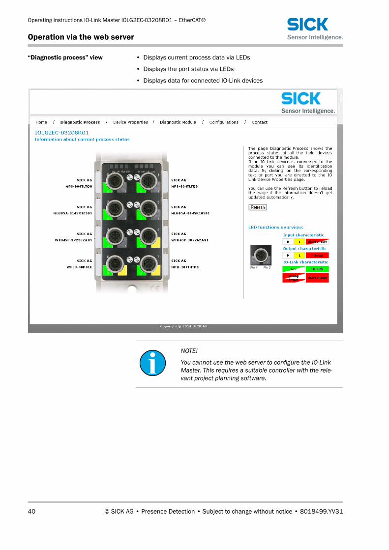
“Diagnostic process” view • Displays current process data via LEDs
• Displays the port status via LEDs
• Displays data for connected IO-Link devices
NOTE!
You cannot use the web server to configure the IO-Link Master. This requires a suitable controller with the rele-vant project planning software.

© SICK AG • Presence Detection • Subject to change without notice • 8018499.YV31 41
Operating instructions IO-Link Master IOLG2EC-03208R01 – EtherCAT®
Operation via the web server
“Device properties” view • Displays the process data for the relevant IO-Link device
> TodisplaytheinformationandconfigurationfortherightIO-Linkdevice,selectthecorrespondingportinthefigureontheright-handside.
NOTE!
You cannot use the web server to set Process values for the IO-Link device.

Operating instructions IO-Link Master IOLG2EC-03208R01 – EtherCAT®
Operation via the web server
42 © SICK AG • Presence Detection • Subject to change without notice • 8018499.YV31
“Device properties” view – port for the desired IO-Link device selected
• ConfigurationoftherelevantIO-Linkdevice
• Parameter data: Read and write IO-Link parameter data. For the indi-ces and subindices, please refer to the operating instructions for the relevant IO-Link device.
• Events: Displays the current events for the IO-Link device
• Parameter server content: Displays the content of the parameter server
“Diagnostic module” view • Displays the current status of the IO-Link Master
• Displays the current status of the network
For a description, see Page 14, Table 4 and Page 14, Table 5.

© SICK AG • Presence Detection • Subject to change without notice • 8018499.YV31 43
Operating instructions IO-Link Master IOLG2EC-03208R01 – EtherCAT®
Operation via the web server
“Configuration”view You can use this view to change the description and position for the IO-Link Master. To change the data, enter the following user name and password:
• User name: sick
• Password: IOLG2

Operating instructions IO-Link Master IOLG2EC-03208R01 – EtherCAT®
Cleaning and maintenance
44 © SICK AG • Presence Detection • Subject to change without notice • 8018499.YV31
“Contact” view • Contact information for SICK AG
9 Cleaning and maintenance
SICK devices are maintenance-free. We do recommend checking the screw and male/female connections and cleaning the device at regular intervals.
10 Disposal
Please observe the following when disposing of the device:
• Do not dispose of the device in domestic refuse.
• Disposeofthedeviceaccordingtotherelevantcountry-specificregula-tions.

© SICK AG • Presence Detection • Subject to change without notice • 8018499.YV31 45
Operating instructions IO-Link Master IOLG2EC-03208R01 – EtherCAT®
Technical data
11 Technical data
NOTE!
You can download, save, and print the relevant on-line data sheet with technical data, dimensions, and connection diagrams for the IO-Link Master online at “www.sick.de”. Enter the order number “6053254” for the IOLG2EC-03208R01 IO-Link Master on the web page.
11.1 Dimensions
USUA
RUNERR
100L/A1
100L/A2
01
01
01
01
01
01
01
01
01
01
23
45
67
LK1IN
LK2OUT
POWER
OUTPOW
ERIN
255P
S↑
21.2
(0.8
3)
37.9
(1.4
9)
0.3
(0.0
1)
68 (2
.68)
64.4
(2.5
4)
Ø 7.
5 (0
.3)
Ø 7.
5 (0
.3)
M12 x 1 (8x)
224 (8.82)
209.4 (8.24)
6.5 (0.26) 7/8" M12 x 1
30.5 (1.20) 25 (0.98) 7/8" M12 x 1 1.8 (0.07)
21.2
(0.8
3)
25 (0.98) 25 (0.98) Fig. 25: Dimensions of the IOLG2EC-03208R01 EtherCAT® IO-Link Master
Dimensions in mm (inch)

Operating instructions IO-Link Master IOLG2EC-03208R01 – EtherCAT®
Technical data
46 © SICK AG • Presence Detection • Subject to change without notice • 8018499.YV31
11.2 Supply
Supply voltage DC 18 V … 30.2 V
Connection 7/8” male connector, 5-pin
Functional grounding 1 FE connection for M4 ground strap
Current consumption at 24 V DC 130 mA
Residual ripple <1%
Input ports/output ports 8 x M12 female connector, 5-pin, A-coded
Table 19: Supply
11.3 EtherCAT®
EtherCAT® port 2 x 100Base-Tx
EtherCAT® port connection 2 x M12 female connector, 4-pin, D-coded
Data transmission rate 10 / 100 Mbit/s
Suitable cable types in accordance with IEEE 802.3
Screened, twisted cable pair, at least STP CAT5 or STP CAT5e
Max. cable length 100 m
Flow control Full duplex (IEEE 802.33x-Pause)
Table 20: EtherCAT®
11.4 Ambient conditions
Mark of conformity CE
EMC EN 61000-6-2
EN 61000-6-4Ambient temperature range • Operation: –5 °C … +70 °C
• Storage: –25 °C … +70 °CEnclosure rating (IEC 60529) IP 67 when plugged in and screwed together
Shock resistance EN 60068-2-27
Vibration resistance EN 60068-2-6, EN 60068-2-64
Table 21: Ambient conditions

© SICK AG • Presence Detection • Subject to change without notice • 8018499.YV31 47
Operating instructions IO-Link Master IOLG2EC-03208R01 – EtherCAT®
Technical data
11.5 Structural design
Dimensions → See Page 45, Chapter 11.1.
Housing material Zinc die cast, matt nickel-plated
Weight Approx. 670 g
Mounting 2 mounting holes for M6 screws
Table 22: Structural design

Operating instructions IO-Link Master IOLG2EC-03208R01 – EtherCAT®
Technical data
48 © SICK AG • Presence Detection • Subject to change without notice • 8018499.YV31

Operating instructions IO-Link Master IOLG2EC-03208R01 – EtherCAT®
Index
49 © SICK AG • Presence Detection • Subject to change without notice • 8018499.YV31
AAmbient conditions ....................................................... 46
CCleaning ......................................................................... 44Configuration ................................................................. 43Connection diagram
EtherCAT ................................................................... 19IO-Link port .............................................................. 19POWER IN supply voltage ........................................ 18POWER OUT supply voltage .................................... 18
Correct use .................................................................... 10Customer service .............................................................9
DDevice properties .......................................................... 41Diagnostic module ........................................................ 42Diagnostic process ........................................................ 40Dimensions .................................................................... 45Display LEDs
Configuration ........................................................... 34Display mode ................................................................. 35Disposal ......................................................................... 44
EElectrical connection..................................................... 16Electrical specialists
Requirement ............................................................ 11EtherCAT
Technical data ......................................................... 46EU declaration of conformity ...........................................9Explanation of symbols ....................................................7
FFunction ......................................................................... 13Functional grounding .................................................... 18Function indicators ....................................................... 14
HHome .............................................................................. 39
IIncorrect use .................................................................. 10IO-Link Master
Electrical connection ............................................... 17
LLEDs ............................................................................... 14Limitation of liability .........................................................8
MMain menu .................................................................... 36Maintenance ................................................................. 44MODULE INFO ............................................................... 36“MODULE INFO” menu .................................................. 36Mounting ........................................................................ 16
OObject directory ............................................................. 30Operating elements ...................................................... 13Operating instructions .....................................................7Operating mode............................................................. 35Operation
On the IO-Link Master ............................................. 34Via the web server ................................................... 37
PParameter server .......................................................... 29Pin/port LEDs
IO-Link port .............................................................. 15Standard I/O port .................................................... 15
Pushbutton descriptions ............................................... 13
QQualifiedpersonnel ....................................................... 11
Requirements .......................................................... 11
SSafety ............................................................................. 10
Electrical connection ............................................... 16Scope of delivery ..............................................................9Setup .............................................................................. 12Status indicators ........................................................... 13Status LEDs
Communication ....................................................... 14IO-Link Master.......................................................... 14
Structural design ........................................................... 47Supply ............................................................................ 46Supply voltage ............................................................... 18System integration ........................................................ 20
TTechnical data ............................................................... 45Trademark.........................................................................7
VValidation ....................................................................... 29
WWelcome page ............................................................... 38
Index

© SICK AG • Presence Detection • Subject to change without notice • 8018499.YV31 50
Operating instructions IO-Link Master IOLG2EC-03208R01 – EtherCAT®
Index

Operating instructions IO-Link Master IOLG2EC-03208R01 – EtherCAT®
51 © SICK AG • Presence Detection • Subject to change without notice • 8018499.YV31

SICK AG | Waldkirch | Germany | www.sick.com
8018499.YV31/2016-07-07∙KOD
/ITL∙(2016-07)∙A44cint43 Australia
Phone +61 3 9457 0600 1800 33 48 02 – tollfreeE-Mail [email protected]
Belgium/LuxembourgPhone +32 (0)2 466 55 66E-Mail [email protected]
BrasilPhone +55 11 3215-4900E-Mail [email protected]
CanadaPhone +1 905 771 14 44E-Mail [email protected]
Česká republikaPhone +420 2 57 91 18 50E-Mail [email protected]
ChinaPhone +86 4000 121 000E-Mail [email protected] +852-2153 6300E-Mail [email protected]
DanmarkPhone +45 45 82 64 00E-Mail [email protected]
DeutschlandPhone +49 211 5301-301E-Mail [email protected]
EspañaPhone +34 93 480 31 00E-Mail [email protected]
FrancePhone +33 1 64 62 35 00E-Mail [email protected]
Great BritainPhone +44 (0)1727 831121E-Mail [email protected]
IndiaPhone +91–22–4033 8333E-Mail [email protected]
IsraelPhone +972-4-6881000E-Mail [email protected]
ItaliaPhone +39 02 27 43 41E-Mail [email protected]
JapanPhone +81 (0)3 5309 2112E-Mail [email protected]
MagyarországPhone +36 1 371 2680E-Mail [email protected]
NederlandPhone +31 (0)30 229 25 44E-Mail [email protected]
Norge Phone +47 67 81 50 00E-Mail [email protected]
ÖsterreichPhone +43 (0)22 36 62 28 8-0E-Mail [email protected]
PolskaPhone +48 22 837 40 50E-Mail [email protected]
RomâniaPhone +40 356 171 120 E-Mail [email protected]
RussiaPhone +7-495-775-05-30E-Mail [email protected]
SchweizPhone +41 41 619 29 39E-Mail [email protected]
SingaporePhone +65 6744 3732E-Mail [email protected]
SlovenijaPhone +386 (0)1-47 69 990E-Mail [email protected]
South AfricaPhone +27 11 472 3733E-Mail [email protected]
South KoreaPhone +82 2 786 6321/4E-Mail [email protected]
SuomiPhone +358-9-25 15 800E-Mail [email protected]
SverigePhone +46 10 110 10 00E-Mail [email protected]
TaiwanPhone +886 2 2375-6288E-Mail [email protected]
TürkiyePhone +90 (216) 528 50 00E-Mail [email protected]
United Arab EmiratesPhone +971 (0) 4 88 65 878E-Mail [email protected]
USA/MéxicoPhone +1(952) 941-6780 1 (800) 325-7425 – tollfreeE-Mail [email protected]
More representatives and agencies at www.sick.com