ems 007/2010. 4x4 and 2x4... · web viewthe unit should be accompanied by a manual liquid soap...
TRANSCRIPT

NATIONAL TREASURY: REPUBLIC OF SOUTH AFRICA
EMERGENCY MEDICAL SERVICES
AMBULANCE CONVERSION TECHNICAL SPECIFICATION: AMBULANCE 4X4 AND 2X4
EMS 002/2018
NOTE:
1. All materials used in the construction of the ambulance conversion are to meet SANAS/SABS standards.
2. Conversion is to be approved by the relevant End-User Department after a “prototype” has been inspected and approved.
3. Contractor must be an accredited ISO 9000 manufacturer.4. All conversion aspects related workmanship must carry at least 36
months warranty.5. Contractors to submit detailed project plan which should include
midway inspection or at any time during production of each vehicle by the end user.
6. Sign off will depend on end user acceptance as per the prototype specification.

List of abbreviations
LHS – Left Hand Side (passenger side)RHS – Right hand side (driver side)OEM – Original equipment manufacturerGMAW – Gas metal arc weldingGTAW - Gas tungsten arc welding

REQUIREMENTS COMMENTSSECTION ONE: VEHICLE EXTERIOR1.1 Take original load bin off vehicle.1.2 Take out leaf springs, add extra leaves and
adjust to suit new body weight1.3 Vehicle chassis needs to be extended with
additional mounting brackets.1.4 Provisions need to be made to accept a
rear bumper step.SECTION TWO: AMBULANCE BODY2.1 The original load box of the body must be
replaced with a new Composite construction Aluminium insulated box type Body.
2.2 The new body will have following external dimensions:Length: 2500mmWidth:1780mmHeight: 1650mm (top of vehicle chassis)
2.3 The sub frame will be constructed from 6,3mm aluminium channel and strongly welded in place. Reinforcing needs to be put in place to hold various attachments on the floor.The main body frame must be of sufficient strength to bear the load imposed on it.The sub frame will be bolted to the chassis by means of steel brackets.16mm HT bolts, washers and 16mm nuts.
2.4 The new body constructed with a cavity of 38mm and have various brackets for internal attachments.
2.5 The entire body to be manufactured from suitable Aluminium Extrusions (Grade 6063) and Aluminium plate (Grade 120044)
2.6 All Aluminium body exterior, Gutter, Front, Rear roof and Side panels are to be bonded onto a main frame using a one component UV resistant high modules Polyurethane based adhesive.
2.7 The entire Aluminium frame, Tail panel, Floor, Storage areas, Door frames and related items to be joined by fusion welding method GMAW or GTAW.
2.8 The entire body must be of sufficient substance as to withstand disintegration in the event off a rollover accident
SECTION THREE: BODY COMPOSITION

3.1 LEFT HAND SIDE:Integrated into the left side it will have compartments/boxes allocated for hand wash unit and bench. The lid of the bench will tip up and also have a tip up backrest for the patient. A single shelf placed inside the bench as well as allowances for a trauma board and scoop stretcher that must be accessed from the outside. It will have 1x eminence O² point by the rear doorIt will also have space for a window.
3.2 RIGHT HAND SIDE:Integrated into the right side it will have a compartment/box allocated for 2x O² cylinders with an inspection hole for monitoring the pressure gauge and 1x eminence point, 1x vacuum point, porta vac pump and an ON/OFF switch.Porta Vac to be supplied by end user as per RT4 specification.It will also have space for a window.
3.3 Bulkhead:The bulkhead will have allocation for a nose cone to hold various items and has a capacity 10kgA window for communication between cab and body, mounting point for folding tray and MI system
3.4 REAR:The rear will have a single door fitted on the right with and aperture size of ± 980mm (w) x 1460mm (H).The door will have a fixed frosted glass, with glazed rubber fitted to the top half of the door and open in a wrap around and have a suitable retainer. A high quality lock needs to be used to lock the door.A single frosted glass to be fitted on the left between the door and post.
2 x grab handles,2 x eye bolts for a loose ramp
3.5 ROOF:The roof will have an escape hatch as well as stiffeners to hold various items like Air conditioner and hand rail
3.6 SPRAY:All exterior work to be sprayed the same colour of the existing vehicle.All interior to be sprayed colour as interior panels.

3.7 FLOOR:The original vehicle floor should be prepared to accept a 15mm thick waterproof plywood floor panel.Packing/spaces are to be fitted within floor corrugations along with suitable reinforcing in same area for attendant seat, stretcher location and other floor fittings.
The plywood floor panel should be precisely cut to fit the original floor.Separate floor panels should be joined by a half-lap method of 20mm. The completed floor sections should be bonded into the vehicle using a polyurethane adhesive.
Floor to be levelled to facilitate stretcher handling and should have a tough, hard-wearing and waterproof finish. Floor finish to be grey (colour code - #575960)Fibre-reinforced vinyl transport sheeting of a minimum of 1.9mm thickness. It should cover the entire floor and fold up all vertical surfaces at least 80mm in the front and 40mm on the sides. Fibre-reinforced vinyl transport sheeting to be fitted by an approved contractor or suitable fitter. The Fibre-reinforced vinyl transport sheeting transport vinyl must be secured to the waterproof plywood with a Transport sheeting appropriate adhesive.
All joints must be seam-welded. All exposed seams must be sealed with a liquid resistant sealer that is capable of withstanding continuous, extended vibrations (gravel road driving)
The extensions from the floor to the sides must be 1-piece with no joints in the corners.
High wear and edge floor areas are to be fitted with an extruded aluminium step edging.
SECTION FOUR: INTERIOR DESIGN4.1 Reinforcement:
Reinforce roof, body sides, floor and front sections of vehicle in order to accept

numerous internal fittings.4.2 The side panels should be manufactured
from a non-porous, smooth, white high-gloss material. The panels should be washable and scratch resistant. The side walls should have a minimum thickness of 4mm. The panels must be secured with 8 x 20 mm dual location plugs or other suitable securing methodThe roof panel should be blue (#009fff hex colour) with decal in white as indicated in the attached picture
4.3 Where the interior panels intersect with the body or fittings, a polyurethane adhesive should be used to form a non-porous seal
4.4 Light weight insulation needs to be placed in between the internal panels and outside skin.
4.5 a)Stretcher specification
1 x Four-castor self-loading ambulance stretcher with elevating head and fixed end will be fitted. The stretcher is to be positioned with the head closes to the front of the vehicle, with suitable leg space for attendant sitting on seat at stretcher head (if body length allows for it).
The stretcher should have as a minimum requirement the following features:
- Self-loading design- 3 x cross-strap restraints- Lightweight, rugged aluminium
construction- High visibility, powder coated frame- Seven height positions- Easy to use release handle design- One-hand release breakaway head
section with safety bar- One-hand release, fold down side rails- One-hand release, multi-positioning
backrest- Adequately sized wheels with sealed
caster and wheel bearings- Sealed bolster mattress- 2 x lap belts and 1 x four-point shoulder
restraintStretcher to be part of the vehicle

conversion – stretcher to be bought off the RT4 contract and type determined by the end user
4.6 Gabbler Rail:An 1820mm Gabbler rail must be fitted on the right hand side approximately 715mm from the floor to center. The Gabbler rail should be fastened securely to the side with 3 x 8mm stainless steel fasteners, and should be spaced away from the body side by a minimum of 40mm.The Gabbler rail should have a certified minimum load capacity of 10kg
4.7 1 x 1kg or 1 x 1.5kg SABS approved, fire extinguisher with steel retaining bracket and retaining “R” clip to be fitted in the driver cab – placement in consultation with end user
4.8 The light switch will be mounted upper right by the door
4.9 A loading light will be fitted on the upper right hand door aperture
4.10
Portable O² bracket to be mounted. Fitted in consultation with the end user
4.11
Invertor to be fitted securely next to O² box
4.12
O² box should have an inspection hole, 1x eminence point, 1x vacuum point, porta vac pump (supplied by end user) and an ON/OFF switch
4.13
Left Hand Side
Waist RailA custom manufactured waist rail is fitted to the LHS of the vehicle. This provides reinforcing along the length of the LH body side, in between the LHS hand wash box and rear apertures. The waist rail is epoxy coated in white to match the finish of the interior panels and is constructed from 1.6mm mild steel.
Integrated into the waist rail are the following:- Mounting points for 3 x passenger
inertia lap belt fastenings. 3 (three) SABS or E marked approved Inertia cap type seat belts are to be supplied and fitted, to be mounted onto a

combination bracket.
- 1 x 12 volt DC hella type socket to be fitted at the forward most point of the waist rail.
4.14
Back RestA backrest is to be securely fitted above the Waist rail. Length: 1750 mm (may require adjusting according to vehicle type), Height: 200 mm x 12mm ply, Depth: 60 mm. It should have a high-density foam insert and be trimmed in a non-absorbent blue (colour code - #009fff) vinyl material
4.15
BenchThe bench will be placed underneath the waist rail and have a high density foam cushion and covered in non-absorbent vinyl material (colour code #009fff) There will also be 2x lap belts and 2x web stalk placed as per end user request.
4.16
Attendants chairA commuter 2000 single blue ( #009fff hex colour) vinyl seat is to be fitted, which is secured by 4 x 10mm, 8.8 grade bolts with heavy duty galvanized fender washers and Nylock nuts to underside of vehicleSeat positioned at the head of the primary stretcher facing the rear doors, sufficient space for attendance legs should be considered within the available interior space.1 (one) SABS or E marked approved Inertia cap type belt is to be supplied and fitted onto the seatLocated beneath attendant seat cushion should be a custom built bracket for secure retention of a standard sharps container. The sharps container should be readily accessible
4.17
Water Hand Washing UnitA mobile, collapsible water hand washing unit must be fitted. The unit should have a minimum capacity of 3 litres and provide at least 15 x 12 second hand washes per filling. The unit should provide self-containment of all waste water with the option of external drainage if needed.
The unit should be accompanied by a manual liquid soap dispenser/or hand

sanitizer dispenser. The dispenser should have a minimum volume of 1 litre. It should dispense 1,5 ml liquid per use and be refillable. An epoxy coated bracket needs to be made to hold dispenser bottle and be securely fastened to the bulkhead.
(Optional. The unit should be accompanied by a transparent paper towel holder and securely fastened to the bulkhead, to hold a minimum of 30 x KIMDRI regular folded hand towels or equivalent)
Placement of hand washing unit:Hand wash unit and its accessories are to be placed in the box provided as mentioned above
4.18
Roof
Air conditioner:
A slim line air conditioner will be placed above the attendant’s seat facing the rear and be connected to the vehicles A/C unitEscape Hatch:
An SABS APPROVED ESCAPE HATCH will be placed in the centre of the roofLight Bracket:The light bracket will follow the full length of the roof both sides and will have a diffuser lens.
Hand rail:
A custom made hand rail for holding onto while in motion. Extensive hand rails should be provided throughout the vehicle, securely fastened to predetermined, reinforced points within the module. Hand rails to be powder coated yellow (colour code f9f036)
Drip:
2x(two) drip hooks will be mounted in the roof( location by end user)
SECTION FIVE: OXYGEN5.1 2x heavy duty bulk oxygen brackets to be
placed inside O² box.

1x portable O² bracket to be mounted on RHS (Location by end user)
5.2 A bullnose oxygen regulator with DISS is to be supplied and fitted.The regulator is to be piped via certified oxygen piping from this compartment into 1x eminence oxygen outlet mounted in the bench seat and 1x eminence oxygen outlet mounted in O² box
5.3 Oxygen pipe should have the following requirements or equivalent :
Reinforced anti-static, low toxic liner. Specially selected high tensile
polyester fibres used at the optimum braid angle of 54° 44’ (54.73°) creates an effective and balanced pressure hose.
Exceptional performance and renowned for reliability.
Conforms to BS EN ISO 5359:2008 meeting the current criteria for use with low pressure medical gases
Cadmium and silicone free. Carefully selected materials
conforming to BS ISO 2878:2005 Electrical Conductivity.
Medical colour standards. Striped hoses for mixed gases.
Resistant to a wide range of chemicals5.4 The oxygen system should be certified,
and a test certificate should be issued with the vehicle
5.5 All pipes connections must be clamped with OERTIKA type clamps or equivalent
NOTE: Oxygen bottles and any oxygen equipment other than stated would be end-user supplied.SECTION SIX: WINDOWS6.1 220V AC Power
1x (one) left and 1x (one) right custom made sliding window will be fitted on each side on the upper part of the body.These windows will be a PLANT ON TYPE window which is securely fastened to the body.Dimensions of these windows are determined by end user.All sliders to be frosted.
6.2 1x (one) frosted shatterproof fixed glass to be fitted in the rear door. Glass to be fitted with glazing rubber.
6.3 1x (one) frosted shatterproof fixed glass to be fitted between the post and rear door. Glass to be fitted

with glazing rubber6.4 1x (one) sliding window to be placed on bulkhead for
communication between cab and attendant.6.5 The driver and passenger door windows shall be fitted
with Anti Smash And Grab 100mic clear Safety Film or equivalent
SECTION SEVEN: ELECTRICALPower Provision & Distribution7.1 220V AC Power7.1.1 A 12V DC to 220V AC 1500W – 2000W Pure sine
wave inverter must be fitted.7.1.2 The inverter shall incorporate a multi stage intelligent
battery charger capable of 35A at 12V7.1.3 The inverter/charger shall conform to EN 60335-1
safety standards (minimum) and 2004/104/EC automotive EMC directive
7.1.4 A remote On/Off switch for the inverter is to be located within the patient compartment. An indicator light is to be provisioned to indicate the presence of 220V power from the inverter.
7.1.5 220V AC is to be distributed via a distribution board to 2 outlets.The distribution board shall be fitted with an earth leakage circuit breaker and a suitably rated overload protection breaker (6A max).Each outlet must contain a standard South African 3 pin 16A (Type D), a Euro (Type J) and a Schuko (Type F) socket. Each outlet to have its own on/off switch
7.1.6 An auto eject electrical input system is to be provisioned on the outside of the vehicle to allow connection to grid (shore) power.Upon sensing engine start, plug ejects from receptacle and away from vehicle path.After eject, weatherproof cover snaps into position over inlet.An indicator light is to be fitted inside the power inlet to indicate the presence of grid power
7.1.7 The power inlet will auto-eject the power supply cable when the vehicle’s ignition switch is turned to the IGN position
7.1.8 A 2.5mm² wire x 20 meter extension lead with matching coupler and real is to be provided
7.2 12V D Power7.2.1 A second, auxiliary battery (12V) is to be fitted. The
battery must be a lead-acid, deep cycle battery with a minimum rating of 80A/h. The second battery is to be connected to the vehicle’s main battery via an automatic isolator/combiner.
7.2.2 The isolator/combiner must engage when either one of the batteries’ voltage exceeds 13.1V and disengage when combined battery voltage is below 12.8V. The Isolator/combiner is to have a continuous current rating of 120A (minimum). Both main and auxiliary side of the isolator/combiner to be fused

(100A).The auxiliary battery 12V DC is to be distributed via a distribution board.
7.2.3 One 12V DC Hella type socket is to be fitted in the patient compartment – one left.
7.2.4 The Hot Water Hand Washing Unit must switch on/off with the vehicle’s ignition switch but power must be provided by the auxiliary battery.
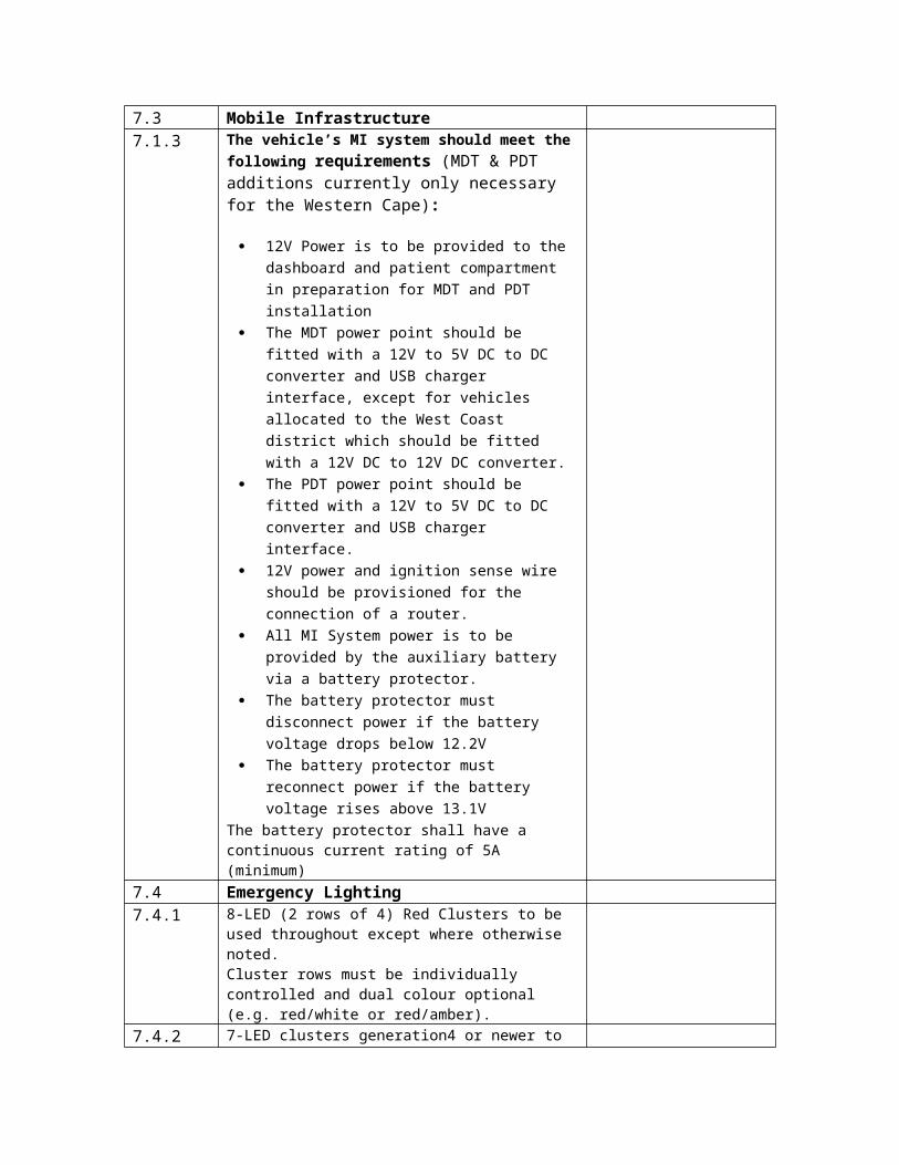
7.3 Mobile Infrastructure7.1.3 The vehicle’s MI system should meet the
following requirements (MDT & PDT additions currently only necessary for the Western Cape):
12V Power is to be provided to the dashboard and patient compartment in preparation for MDT and PDT installation
The MDT power point should be fitted with a 12V to 5V DC to DC converter and USB charger interface, except for vehicles allocated to the West Coast district which should be fitted with a 12V DC to 12V DC converter.
The PDT power point should be fitted with a 12V to 5V DC to DC converter and USB charger interface.
12V power and ignition sense wire should be provisioned for the connection of a router.
All MI System power is to be provided by the auxiliary battery via a battery protector.
The battery protector must disconnect power if the battery voltage drops below 12.2V
The battery protector must reconnect power if the battery voltage rises above 13.1V
The battery protector shall have a continuous current rating of 5A (minimum)
7.4 Emergency Lighting7.4.1 8-LED (2 rows of 4) Red Clusters to be used
throughout except where otherwise noted.Cluster rows must be individually controlled and dual colour optional (e.g. red/white or red/amber).
7.4.2 7-LED clusters generation4 or newer to be used on the nose cone.Lights need to be arranged five forward facing clusters. One cluster at 90° to be fitted on the left and right of the nose cone.
7.4.3 On each side of the vehicle, one cluster to be positioned top rear and top front.
7.4.4 On the rear door, one cluster at top left, top right and top center.
7.4.5 Two clusters to be fitted in the radiator grill (left and right). These clusters to be red/white. Two 4-LED clusters may be substituted for a single 8-LED cluster where the mounting of an 8-LED cluster is impractical.
7.4.6 A two channel flasher unit is to be used to flash all

clusters7.4.7 Single colour clusters must flash both rows
simultaneously. Dual colour cluster must flash each colour alternately
7.5 Interior LightingAll interior lighting should be rigid LED strip lights, using 50/50 SMT Cool White LED at 30 LED per meter unless otherwise notedAll LED lights should be mounted behind a light diffuser lensLights switch should be clearly marked and switched off simultaneously.Lights switch must be easily accessible from the outsidePatient compartment ceiling lights should run the full length of the vehicle on both sidesA LED 27 watt loading light should be fitted inside at the right hand upper corner of the rear door aperture. Switch should be easily accessible from the rear
7.6 Exterior LightingThe driver and passenger door to be fitted with red LED strip light along the trailing edge of the door.20cm per strip; 6 x 50/50 SMT LED per strip.Strip light to switch on when door is opened and off when door is closed (using existing door switches).
7.7 SirenOutput 200W with 1 speaker.
Wail, yelp & phaser tones. Dual tone (stereo) - one tone through speaker. Touch control panel.Horn ring control (press twice to activate response mode - lights & siren on – press again to change tone; press twice to silence siren; press once to switch lights off.
7.8 Park Distance ControlPark distance control to be fitted, with 4 x bumper mount sensors to detect the proximity of objects up to 1.5m away.
Features required: Slow beeps are sounded when an object is
detected with the 1.5 - 0.9m range Fast beeps are sounded when an object is
detected with the 0.9 – 0.45m range A continuous tone is sounded if an object is
detected with 0.45mAuto-on when reverse gear is selected
7.9 Rear CameraRear CameraA rear facing camera and LED spot light shall be mounted on the rear above the doors.The screen for the camera shall be incorporated into the dash.Loading lights needs to be incorporated with the

camera while in motion. A buzzer with a timer needs to be installed to notify the driver of activation while driving.
SECTION EIGHT: BODY REFURBISHMENT & LIFESPAN8.1 The ambulance conversion components must be
manufactured in such a manner that they provide two lifespans of approximately 4 years each.After 4 years of normal service life, selected components should have the ability to be removed from the base vehicle and undergo refurbishment in preparation for fitting into a new vehicle, so as to provide an additional 4 years of service after refurbishment.
8.2 The refurbishment of these components should result in a minimum of a 20% saving against the cost of a brand new ambulance conversion, excluding equipment and base vehicle.
SECTION NINE: ADDITIONAL REQUIREMENTS9.1 Heavy Duty Off Road Bumper.
A LED spot light to go mounted on nudge bar must have a separate on/off switch in the driving cab, clearly marked with an LED lightHeavy Duty Off Road Bumper fitment to be decided by end user. OEM approved and fitted
9.2 Vehicle must include the supply and installation of an UV light effective against micro-organisms which is equivalent to the Sani 18. UV lamp capable of emitting UV-C light at a wavelength of 253.7/254 nm and should be 12-24 Volt.
The unit must have a twelve month guarantee and a second year service plan.
9.3 Air-Conditioning system for the patient compartment of vehicle to be supplied, installed, fitted and included in the final pricing schedule as an Must carry a minimum of a 3-year warranty.
9.4 All instruments, gauges and switches shall be clearly marked as to their use. Dymo stencilling shall not be accepted.
SECTION 10: DRAWINGSThe following detailed drawings shall be included in the Bid submission.Failing to do so will result in rejection of Bid.10.1 Side view of Ambulance
Total Length, height, and loading height Overall height Window position and dimension. Sign writing and stripping Compartment mounting to chassis Load distribution of complete Ambulance

from body builderBody construction showing material used and dimension
10.2 Rear view of Ambulance Door dimension Interior dimensions Plan of outlay of equipment Rear view showing placement of light
units Detail of attachments to hold drip bottles
and stretcher anchoring devices Detailed drawing of body construction
showing material used and dimensions Diagram of battery linking (management
system)10.3 Front view of Ambulance
Front view indicating light unit placement, type and sign writing
10.4 Top view of patient compartment Plan indicating the compartment layout
from a top view.Complete diagram indicating the electrical management system
10.5 Spare wheel mounting10.6 Full vehicle wiring diagram10.7 Drawings and diagrams subject to the type of base
vehicle selected. To be provided upon selection if different from section 11
SECTION 11 – PAINTING AND MARKING11.1 Yellow and green segmented Battenberg style,
high visibility markings made from reflective material on the LHS and RHS of vehicle
11.2 Star of life on LHS and RHS with Protekta Glaze clear coat for added scratch resistance and UV protection.
11.3 To be indicated on the LHS and RHS respectively:
1. The respective “Province” 2. Emergency Medical Services3. Fleet number
11.4 Telephone icon with ‘112’ on LHS and RHS
11.5 SA flag depicted on LHS and RHS
11.6 Provincial Coat of Arms to be displayed on both cab doors. With Protekta Glaze clear coat for added scratch resistance and UV protection

11.7 Star of life on Bonnet with Protekta Glaze clear coat for added scratch resistance and UV protection.
11.8 The word ‘Ambulance’ to be displayed on bonnet, with a reflective strip below. Size: 600mm x 150mm as well as on the rear of vehicle
11.9 The word ‘Diesel/Petrol’ (vehicle dependent) to be displayed below the fuel cap
11.10 High visibility segmented chevron patterned reflective marking to cover the entire back panel of the vehicle. Vinyl specification: Orange and lime green 3M
11.11 Large call sign to be displayed on vehicle roof (approximately 785 x 355mm)
11.12 Printed on 3M IJ 680-10 cast reflective digital print vinyl – white overlamed.
11.13 The words “No Smoking” decal to be stuck on the inside where visible (or alternatively the international “No Smoking” pictograph sign may be applied). This will also be required in the drivers compartment
11.14 All vehicles will be marked as per provincial end-user requirements in 3M Vehicle reflective materials as per the national branding specifications
11.15 The words “Emergency Exit” to be displayed on rear and sliding doors
ADDITIONAL ACCESSORIES
1. Flashing red lights connected to the back door of the ambulance2. Separate switches for lights inside passenger compartment3. Optional bull bar to meet the following requirements – comply with vehicle
safety features – should be OEM approved, should have the option of not reducing the ground clearance of the vehicle and additional lights (end user specified).
4. Inverter should be standard (pure sine wave); 1500 - 2000 Watt. Modifications to inverter will not be accepted

1. HOMOLOGATION & CERTIFICATION
a) The conversion must be supplied complete with Natis documentation and certification including:
A Certified Weight Bridge Certificate stating the Total Tare Mass of the Converted Vehicle.
All Ambulance Conversion Homologation Documentation. A Manufacturer’s/ End Manufacturers Certificate Stating: Body conversion
Number AND NRCS Natis Number applicable to the particular conversion. Any other Information related to the Conversion. Must stipulate the amount of seated patients the vehicle may carry post
conversion
b) The unit should comply with all relative legislation pertaining to the conversion.
2. ADDITIONAL CONDITIONS WITH PENALTIES
a) The successful body converter must construct a prototype within 5 weeks for inspection and testing by a representative of the Department of Transport and end user for approval and/or possible alterations, before constructing any subsequent units.
b) The prototype unit, when accepted, shall serve as a standard for the construction of further units.
c) The End-User reserves the right of inspection of the prototype, as well as of any other units, at any stage of their construction.
d) A representative of the bid company shall be present during the inspections to record all faults and decisions for future reference
The End-User Department is at liberty to reject and return equipment supplied should there be any deviation from the information given in the above schedule or elsewhere in this bid and where relevant should there be any difference between masses given in the schedule and the actual mass measuring bridge figures
The completed vehicle must be handed over to the End-User Department with the following documentation.
a) Certified weigh bridge certificate stating the total Tare mass
b) Relevant body homologation documentationc) Manufacture certificate with body number, NATIS number and conversion mass
All Bidders must be registered as a Manufacturer, Builder and Importer of motor vehicles as per National Road Traffic Act 1996 Act 93 section 5
The installer of the Oxygen piping must issue a Test and compliance certificate.
GUARANTEE
The complete body must be guaranteed for at least four (4) years against rust to the body work or paint defects; fair wear and tear excluded.
All the electrical equipment including the warning lights and sirens must be guaranteed for 36 months.
DELIVERY
Bidders must specify dispatch dates clearly in terms of lead time, rate of dispatch and completion of contract.
DEVIATIONS
Electrical conversion – no deviations will be accepted. Failure to correct will result in penalties and will result in end-user not accepting the vehicle and the converter reported to the OEM with the view of blacklisting.
Mechanical conversion – no deviations will be accepted. Failure to correct will result in penalties and will result in end-user not accepting the vehicle and the converter reported to the OEM with the view of blacklisting
Structural conversion – no deviations will be accepted. Failure to correct will result in penalties and will result in end-user not accepting the vehicle and the converter reported to the OEM with the view of blacklisting
Branding - no deviations will be accepted. Failure to correct will result in penalties and will result in end-user not accepting the vehicle and the converter reported to the OEM with the view of blacklisting.


