emr’16 udes - longueuil june 2016 - emrwebsite - … - thermal... · 08/07/2016 1 emr’16 udes -...
TRANSCRIPT
08/07/2016
1
EMR’16
UdeS - Longueuil
June 2016
Summer School EMR’16
“Energetic Macroscopic Representation”
Thermal hybridization and heating
strategies of a fuel cell / battery pack
system using EMR
A. Amamou1, L. Boulon1,2, S.Kelouwani1, K.Agbossou1,2, P.Sicard2
1Institut de Recherche sur l’Hydrogène
2Groupe de Recherche en Électronique Industrielle
Université du Québec à Trois-Rivières, Québec, Canada
EMR’16
UdeS - Longueuil
June 2016
Summer School EMR’16
“Energetic Macroscopic Representation”
1- Introduction
2- Thermal management strategies
3- System Description
4- Model development
5- Simulation Results
6- Conclusion
08/07/2016
2
EMR’16
UdeS - Longueuil
June 2016
Summer School EMR’16
“Energetic Macroscopic Representation”
«Introduction»
EMR’16
UdeS - Longueuil
June 2016
Summer School EMR’16
“Energetic Macroscopic Representation”
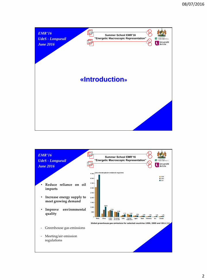
• Reduce reliance on oilimports
• Increase energy supply tomeet growing demand
• Improve environmentalquality
- Greenhouse gas emissions
- Meeting/air emissionregulations
Global greenhouse gas emissions for selected countries 1990, 2005 and 2011 [1]

08/07/2016
3
EMR’16
UdeS - Longueuil
June 2016
Summer School EMR’16
“Energetic Macroscopic Representation”
Zero emission
High fuel efficiency high power densities
Quick response
low operating temperature
EMR’16
UdeS - Longueuil
June 2016
Summer School EMR’16
“Energetic Macroscopic Representation”
The formed ice can :
• Reduce the performance
• Damage the cell components
• Block the gas passages
• Coat the catalyst
• lead to cold start failure

08/07/2016
4
EMR’16
UdeS - Longueuil
June 2016
Summer School EMR’16
“Energetic Macroscopic Representation”
Technical Solutions for heating up the fuel cell
Waste heat
External fluid based warm-up systems
Hot air forced ventilation using a
compressor
[LHO,07]
The exothermicchemical reaction Operate the stack
near short circuit conditions
EMR’16
UdeS - Longueuil
June 2016
Summer School EMR’16
“Energetic Macroscopic Representation”
«Thermal management strategies»

08/07/2016
5
EMR’16
UdeS - Longueuil
June 2016
Summer School EMR’16
“Energetic Macroscopic Representation”
Thermal management
strategies
Keep warm strategy
Thaw at start strategy
Maximize the energy efficiency and optimize the startup time
0 1 2 3 4 5 6 7 8 9 10 11 12 13 14 15 16 17 18 19 20 21 22-30
-20
-10
0
10
20
30
40
50
60
Time (hour)
Te
mp
era
ture
(°C
)
Thaw at Start strategy
Keep-Warm strategy
Fuel cell temperature evolution after shutdown for both strategies at -20 °C
EMR’16
UdeS - Longueuil
June 2016
Summer School EMR’16
“Energetic Macroscopic Representation”
«System Description»

08/07/2016
6
EMR’16
UdeS - Longueuil
June 2016
Summer School EMR’16
“Energetic Macroscopic Representation”
PEMFC
Heater
Battery
Natural convective
heat transfer
m w
Tfc
Tamb
Tw,in
Tw,out
Electrical connectionHeating fluid flow
Heat flow
EMR’16
UdeS - Longueuil
June 2016
Summer School EMR’16
“Energetic Macroscopic Representation”
• A Proton Exchange Membrane Fuel Cells with 25 cells (Hyteon).
• A heater with a maximum heating power of 5 kW.
• An anti-freeze fluid (a mixture of water and glycol)
• A Lithium GBS-LFMP100Ah battery with 32 cells
Parameters Values
Fuel cellN 23 cells
mfc 12 [kg]Cfc 700 [J·kg-1·K-1]
Tfc,min 5°CTfc,max 60°C
Nominal voltage (V) 3.2
Max.
discharging
current
Consistent
current
<= 300
Impulse current <= 1000
Internal resistance 1.8 mΩ
Working temperature [-20°C ; 65°C]
Energy
delivered at
-20°C (Wh)
Discharging
current (A) : 50183
Discharging
current (A) :
100
215
Battery discharging cycles and battery temperature evolutions atfour temperatures tests for a constant discharging current of 50A [3].
Characteristics of Lithium GBS-LFMP100Ah battery [3].

08/07/2016
7
EMR’16
UdeS - Longueuil
June 2016
Summer School EMR’16
“Energetic Macroscopic Representation”
«Model development»
EMR’16
UdeS - Longueuil
June 2016
Summer School EMR’16
“Energetic Macroscopic Representation”
Electro-thermal model
• Determine the heating time, power and energy requirements for both strategies;
• Energetic Macroscopic Representation (EMR) is used to represent the model;
• Inputs : Flow rate of fluid (mw), heating power (Phemax);
• Outputs : Fuel cell temperatures (Tfc), power and energy requirements (Phe, Ehe), Heating time (ts );
Electrical modelV = OCV – r * i
Phe = R * i²
Thermal modelmW CW TW = Phe - 𝑤ℎ𝑒mFC CFC Tfc = - 𝑎𝑚𝑏 + 𝑤ℎ𝑒
𝑄𝑤ℎ𝑒 = Kw (Tw,in - Tfc)𝑎𝑚𝑏= hnc Snc (Tfc - Tamb)
Electrothermal model linked by a heater
Phemax
Outputs
Outputs
(Tfc0, Tfc,ref ,Tw0, Tamb)
(power and energy requirements (Phe, Ehe))
Inputs(Tfc0 ,Tfc,ref ,Tw0
,Tamb , Phemax)
08/07/2016
8
EMR’16
UdeS - Longueuil
June 2016
Summer School EMR’16
“Energetic Macroscopic Representation”
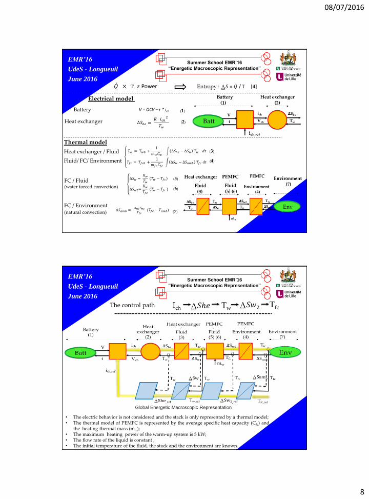
Electrical model
V = OCV – r * ich
∆𝑆ℎ𝑒 =𝑅 𝑖𝑐ℎ
2
𝑇𝑤
Battery
Heat exchanger
Thermal model
Heat exchanger / Fluid
Fluid/ FC/ Environment
FC / Fluid(water forced convection)
FC / Environment(natural convection)
Entropy : 𝑆 = / T [4] × T ≠ Power
𝑇𝑤 = 𝑇𝑤0 +1
𝑚𝑤𝐶𝑤 ∆𝑆ℎ𝑒 − ∆𝑆𝑤 𝑇𝑤 𝑑𝑡
𝑇𝑓𝑐 = 𝑇𝑓𝑐0 +1
𝑚𝑓𝑐𝐶𝑓𝑐 ∆𝑆𝑤 − ∆𝑆𝑎𝑚𝑏 𝑇𝑓𝑐 𝑑𝑡
∆𝑆𝑤 =𝐾𝑤𝑇𝑤(𝑇𝑤 − 𝑇𝑓𝑐)
∆𝑆𝑤2=𝐾𝑤𝑇𝑓𝑐
(𝑇𝑤 − 𝑇𝑓𝑐 )
∆𝑆𝑎𝑚𝑏 =ℎ𝑛𝑐 𝑆𝑛𝑐
𝑇𝑓𝑐(𝑇𝑓𝑐 − 𝑇𝑎𝑚𝑏)
(1)
(2)
(3)
(4)
(5)
(6)
(7)
EMR’16
UdeS - Longueuil
June 2016
Summer School EMR’16
“Energetic Macroscopic Representation”
• The electric behavior is not considered and the stack is only represented by a thermal model;• The thermal model of PEMFC is represented by the average specific heat capacity (Cfc) and
the heating thermal mass (mfc);• The maximum heating power of the warm-up system is 5 kW;• The flow rate of the liquid is constant ;• The initial temperature of the fluid, the stack and the environment are known.
Global Energetic Macroscopic Representation
The control path

08/07/2016
9
EMR’16
UdeS - Longueuil
June 2016
Summer School EMR’16
“Energetic Macroscopic Representation”
«Simulation Results»
EMR’16
UdeS - Longueuil
June 2016
Summer School EMR’16
“Energetic Macroscopic Representation”
0 1 2 3 4 5 6 7 8 9 10 11 12 13 14
-20
-10
0
10
20
30
40
50
60
Te
mp
era
ture
(°C
)
Thaw at Start strategy
Keep-Warm strategy
0 1 2 3 4 5 6 7 8 9 10 11 12 13 140
100
200
300
400
500
600
700
800
900
1 000
Time (hour)
En
erg
y r
eq
uire
d (
KJ)
D
Keep Warm
• The Keep Warm strategy continuouslyrequires energy;
• The Keep-Warm strategy does not allow thestack to freeze and Tfc remains in itstemperature operating range;
• A low heating power (383 W) is required tokeep Tfc around Tfcmin at -20°C.
Thaw at Start strategy
• Energy requirement depends only on theinitial stack temperature;
• Energy requirement does not vary with vehiclestorage time;
• A high heating power (5 KW) is required toraise Tfc from subfreezing temperature to Tfcminduring a certain heating time (ts).
Comparison of energy consumption between Thaw at Start and Keep- Warm strategies at -20°C

08/07/2016
10
EMR’16
UdeS - Longueuil
June 2016
Summer School EMR’16
“Energetic Macroscopic Representation”
-30 -25 -20 -15 -10 -5 00
2
4
6
8
10
12
14
16
18
20
22
Temperatures (°C)
Tim
e (
ho
ur)
-40°-35°-30°-25°-20°-15°-10°-5°0°5°0
10
20
30
40
50
60
70
80
90
100
110
120
130
140
Temperatures (°C)
He
atin
g tim
e (
s)
• A higher temperature provides a significantincrease in D (by roughly 15 hours for anambient temperature rising from -20°C to 0°C);
• D is highly dependent on the ambienttemperature.
• Decreasing Tamb provides a significantincrease in ts (by roughly 101 seconds for anambient temperature drop from 0°C to -40°C);
• ts highly depends on the heating power andambient temperature;
• The Keep Warm strategy is always moreadvantageous in term of cold start-up time.
The break-even parking duration (D) evolution curve for various ambient temperatures
Heating time evolution of Thaw at Start strategy for different ambient temperatures
EMR’16
UdeS - Longueuil
June 2016
Summer School EMR’16
“Energetic Macroscopic Representation”
«Conclusion»

08/07/2016
11
EMR’16
UdeS - Longueuil
June 2016
Summer School EMR’16
“Energetic Macroscopic Representation”
Conclusion
• The main focus of this study is to present a thermal management system modelthat allows the comparison of energy, power and heating time requirements forthe Keep Warm and Thaw at Start strategies;
• Simulation results show that the Keep-Warm strategy is more effective for a shortparking time and for mild sub-freezing temperatures but becomes inefficient forlong parking time;
• The Thaw at Start strategy requires less energy for long parking time, yet,requests high-power and significant time to start;
• Ambient temperature and parking time are the most important factors affectingthe cold startup time and energy requirements.
EMR’16
UdeS - Longueuil
June 2016
Summer School EMR’16
“Energetic Macroscopic Representation”
Conclusion
• After this study, we have chosen the thaw at start stategy for cold startup becauseit’s difficult to predict the parking time
• After that, we developed an experimental test to identify the critical parametersfor cold startup of PEMFC like stochiometrie, short circuit, voltage, hydrogenpressure and purge
• A semi-empirical model has been proposed and tested for online identification inorder to improve the cold startup from -20°C

08/07/2016
12
EMR’16
UdeS - Longueuil
June 2016
Summer School EMR’16
“Energetic Macroscopic Representation”
« BIOGRAPHIES AND REFERENCES »
EMR’16
UdeS - Longueuil
June 2016
Summer School EMR’16
“Energetic Macroscopic Representation”
[1] R. n. Canada. (2013). Global greenhouse gas emissions for selected countries 1990, 2005 and
2011. Available: http://www.rncan.gc.ca/energie
[2] R. n. Canada. (2013). Distribution of greenhouse gas emissions by economic sector, Canada, 2013. Available: http://www.rncan.gc.ca/energie
[3] J. Jaguemont, L. Boulon, Y. Dube, and D. Poudrier, "Low Temperature Discharge Cycle Tests for a Lithium Ion Cell," in 2014 IEEE Vehicle Power and Propulsion Conference (VPPC), 2014, pp. 1-6.
[4] L. Boulon, THESE, "Mod´elisation multiphysique des ´el´ements de stockage et de conversion d’´energie pour les v´ehicules ´electriques hybrides. Approche syst´emique pour la gestion d’´energie, 2009, pp. 25-80.

08/07/2016
13
EMR’16
UdeS - Longueuil
June 2016
Summer School EMR’16
“Energetic Macroscopic Representation”