employment of amphibious assault vehicles (aavs)
TRANSCRIPT

MCWP 3-13 w/chg 1
Employment of Amphibious Assault Vehicles (AAVs)
U.S. Marine Corps
DISTRIBUTION STATEMENT A: Approved for public release; distribution is unlimited.
PCN 143 000103 00

To Our Readers
Changes: Readers of this publication are encouraged to submit suggestions and changes that will improve it. Recommendations may be sent directly to Commanding General, Marine Corps Combat Development Command, Doctrine Division (C 42), 3300 Russell Road, Suite 318A, Quantico, VA 22134-5021 or by fax to 703-784-2917 (DSN 278-2917) or by E-mail to [email protected]. Recommendations should include the following information:
l Location of changePublication number and titleCurrent page numberParagraph number (if applicable)Line numberFigure or table number (if applicable)
l Nature of changeAdd, deleteProposed new text, preferably double-spaced and typewritten
l Justification and/or source of change
Additional copies: A printed copy of this publication may be obtained from Marine Corps Logistics Base, Albany, GA 31704-5001, by following the instructions in MCBul 5600, Marine Corps Doctrinal Publications Status. An electronic copy may be obtained from the Doctrine Division, MCCDC, world wide web home page which is found at the following uni-versal reference locator: http://www.doctrine.usmc.mil.
Unless otherwise stated, whenever the masculine gender is used, both men and women are included.

DEPARTMENT OF THE NAVY Headquarters United States Marine Corps
Washington, DC 20380-1775
17 February 2005
CHANGE 1 to MCWP 3-13 1. Marine Corps Warfighting Publication (MCWP) 3-13, Employment of Amphibious Assault
Vehicles, should be changed as follows:
a. On page 1-7 of Chapter 1, in “Assault Amphibian Section,” delete sentences two and three and replace with, “The Rifle Platoon Commander exercises maneuver control of his platoon through the AAV Section Leader. While mounted or dismounted, the Rifle Platoon Commander coordinates AAV direct fires through the AAV Section Leader.”
b. On page 2-2 of Chapter 2, in “Assault Amphibian Platoon,” paragraph 2, delete
sentences three, four and five and replace with, “The Rifle Company Commander exercises maneuver control of his company through the AA Platoon Commander. While mounted or dismounted, the Rifle Company Commander coordinates AAV direct fires through the AAV Platoon Commander.”
c. On page 3-7 of Chapter 3, in “Planning,” delete sentence three, which currently reads,
“During this period, the AA unit leader maintains TACON over the unit.” d. On page 3-17 of Chapter 3, in “The Assault,” delete the first sentence, which currently
reads, “AA unit leaders, in conjunction with the designated PCO, maintain TACON of AAVs and embarked troops during waterborne movement.”
2. Reviewed and approved this date.
BY DIRECTION OF THE COMMANDANT OF THE MARINE CORPS
J. N. MATTIS Lieutenant General, U.S. Marine Corps
Commanding General Marine Corps Combat Development Command
PCN: 143 000103 01

DEPARTMENT OF THE NAVYHeadquarters United States Marine Corps
Washington, D.C. 20380-1775
10 September 2003
FOREWORD
Marine Corps Warfighting Publication (MCWP) 3-13, Employment of Amphibi-ous Assault Vehicles, provides the doctrinal basis for the use of amphibiousassault vehicles (AAVs) in support of Marine air-ground task force (MAGTF)operations. This publication addresses the mechanized capability of the assaultamphibian unit, section, and platoon in support of MAGTF missions. Thesemissions include seizure and defense of naval and air bases, conduct of landoperations essential to naval operations, and sustained operations ashore thatsupport joint or combined force land operations.
The target audience for MCWP 3-13 is officers and staff noncommissioned offic-ers serving as members of MAGTF staffs and assault amphibian battalions. Thepublication provides information for consideration in the planning and employ-ment of AAVs in combat operations and military operations other than war.
Reviewed and approved this date.
BY DIRECTION OF THE COMMANDANT OF THE MARINE CORPS
EDWARD HANLON, JR.Lieutenant General, U.S. Marine Corps
Commanding GeneralMarine Corps Combat Development Command
Publication Control Number: 143 000103 00
DISTRIBUTION STATEMENT A: Approved for public release; distribution isunlimited.
TABLE OF CONTENTS
Chapter 1. FundamentalsAAV Capabilities . . . . . . . . . . . . . . . . . . . . . . . . . . . . . . . . . . . . . . . . . . . . . 1-1
Armor Protection. . . . . . . . . . . . . . . . . . . . . . . . . . . . . . . . . . . . . . . . . . 1-1Land Operation . . . . . . . . . . . . . . . . . . . . . . . . . . . . . . . . . . . . . . . . . . . 1-1Water Operation . . . . . . . . . . . . . . . . . . . . . . . . . . . . . . . . . . . . . . . . . . 1-1
Types of AAVs . . . . . . . . . . . . . . . . . . . . . . . . . . . . . . . . . . . . . . . . . . . . . . . 1-2AAVP7A1 and AAV7A1 Reliability, Availability, and
Maintainability/Rebuild to Standard . . . . . . . . . . . . . . . . . . . . . . . 1-2AAVC7A1. . . . . . . . . . . . . . . . . . . . . . . . . . . . . . . . . . . . . . . . . . . . . . . 1-3AAVR7A1. . . . . . . . . . . . . . . . . . . . . . . . . . . . . . . . . . . . . . . . . . . . . . . 1-3
Organization . . . . . . . . . . . . . . . . . . . . . . . . . . . . . . . . . . . . . . . . . . . . . . . . . 1-4Assault Amphibian Battalion . . . . . . . . . . . . . . . . . . . . . . . . . . . . . . . . 1-4Assault Amphibian Battalion, Headquarters and Service Company. . . 1-4Assault Amphibian Company . . . . . . . . . . . . . . . . . . . . . . . . . . . . . . . . 1-6Assault Amphibian Platoon. . . . . . . . . . . . . . . . . . . . . . . . . . . . . . . . . . 1-7Assault Amphibian Section. . . . . . . . . . . . . . . . . . . . . . . . . . . . . . . . . . 1-7Assault Amphibian Crew . . . . . . . . . . . . . . . . . . . . . . . . . . . . . . . . . . . 1-7
Chapter 2. Operational PrinciplesCommand Relationships . . . . . . . . . . . . . . . . . . . . . . . . . . . . . . . . . . . . . . . . 2-1
Operational Control. . . . . . . . . . . . . . . . . . . . . . . . . . . . . . . . . . . . . . . . 2-1Administrative Control . . . . . . . . . . . . . . . . . . . . . . . . . . . . . . . . . . . . . 2-1Assault Amphibian Battalion . . . . . . . . . . . . . . . . . . . . . . . . . . . . . . . . 2-1Assault Amphibian Company . . . . . . . . . . . . . . . . . . . . . . . . . . . . . . . . 2-2Assault Amphibian Platoon. . . . . . . . . . . . . . . . . . . . . . . . . . . . . . . . . . 2-2Assault Amphibian Section. . . . . . . . . . . . . . . . . . . . . . . . . . . . . . . . . . 2-2
Task Organization . . . . . . . . . . . . . . . . . . . . . . . . . . . . . . . . . . . . . . . . . . . . . 2-2Fundamentals . . . . . . . . . . . . . . . . . . . . . . . . . . . . . . . . . . . . . . . . . . . . 2-3Cross Attachment . . . . . . . . . . . . . . . . . . . . . . . . . . . . . . . . . . . . . . . . . 2-3Combat Support. . . . . . . . . . . . . . . . . . . . . . . . . . . . . . . . . . . . . . . . . . . 2-4AAV Allocations. . . . . . . . . . . . . . . . . . . . . . . . . . . . . . . . . . . . . . . . . . 2-6
Movement . . . . . . . . . . . . . . . . . . . . . . . . . . . . . . . . . . . . . . . . . . . . . . . . . . . 2-7Control. . . . . . . . . . . . . . . . . . . . . . . . . . . . . . . . . . . . . . . . . . . . . . . . . . 2-7Considerations. . . . . . . . . . . . . . . . . . . . . . . . . . . . . . . . . . . . . . . . . . . . 2-7

iv _______________________________________________________________________________________________________ MCWP 3-13
Chapter 3. Amphibious OperationsTypes of Operations . . . . . . . . . . . . . . . . . . . . . . . . . . . . . . . . . . . . . . . . . . . 3-1
Assault . . . . . . . . . . . . . . . . . . . . . . . . . . . . . . . . . . . . . . . . . . . . . . . . . 3-1Raid . . . . . . . . . . . . . . . . . . . . . . . . . . . . . . . . . . . . . . . . . . . . . . . . . . . 3-1Demonstration . . . . . . . . . . . . . . . . . . . . . . . . . . . . . . . . . . . . . . . . . . . 3-2Withdrawal. . . . . . . . . . . . . . . . . . . . . . . . . . . . . . . . . . . . . . . . . . . . . . 3-2Military Operations Other Than War. . . . . . . . . . . . . . . . . . . . . . . . . . 3-2
Intelligence Requirements . . . . . . . . . . . . . . . . . . . . . . . . . . . . . . . . . . . . . . 3-2Hydrography . . . . . . . . . . . . . . . . . . . . . . . . . . . . . . . . . . . . . . . . . . . . 3-2Enemy Defenses. . . . . . . . . . . . . . . . . . . . . . . . . . . . . . . . . . . . . . . . . . 3-6Sources of Hydrographic Information . . . . . . . . . . . . . . . . . . . . . . . . . 3-7
Planning . . . . . . . . . . . . . . . . . . . . . . . . . . . . . . . . . . . . . . . . . . . . . . . . . . . . 3-7Assault Amphibian Unit Special Staff Officer . . . . . . . . . . . . . . . . . . 3-7Organization for Amphibious Assaults . . . . . . . . . . . . . . . . . . . . . . . . 3-8Landing Plan . . . . . . . . . . . . . . . . . . . . . . . . . . . . . . . . . . . . . . . . . . . . 3-10Preparation of Landing Documents . . . . . . . . . . . . . . . . . . . . . . . . . . . 3-10Organization of the Amphibious Objective Area . . . . . . . . . . . . . . . . 3-10Launch Planning . . . . . . . . . . . . . . . . . . . . . . . . . . . . . . . . . . . . . . . . . 3-12AAV Maximum Ship-to-Shore Swim Distance. . . . . . . . . . . . . . . . . . 3-12
Embarkation . . . . . . . . . . . . . . . . . . . . . . . . . . . . . . . . . . . . . . . . . . . . . . . . . 3-12Amphibious Shipping Characteristics . . . . . . . . . . . . . . . . . . . . . . . . . 3-12Embarkation Planning . . . . . . . . . . . . . . . . . . . . . . . . . . . . . . . . . . . . . 3-12Embarkation of AAVs . . . . . . . . . . . . . . . . . . . . . . . . . . . . . . . . . . . . . 3-13Securing AAVs . . . . . . . . . . . . . . . . . . . . . . . . . . . . . . . . . . . . . . . . . . 3-15
Rehearsal and Movement. . . . . . . . . . . . . . . . . . . . . . . . . . . . . . . . . . . . . . . 3-15Planning Considerations . . . . . . . . . . . . . . . . . . . . . . . . . . . . . . . . . . . 3-16Types . . . . . . . . . . . . . . . . . . . . . . . . . . . . . . . . . . . . . . . . . . . . . . . . . . 3-16Preoperational Briefing and Security . . . . . . . . . . . . . . . . . . . . . . . . . . 3-17Unit Preparation . . . . . . . . . . . . . . . . . . . . . . . . . . . . . . . . . . . . . . . . . . 3-17
The Assault . . . . . . . . . . . . . . . . . . . . . . . . . . . . . . . . . . . . . . . . . . . . . . . . . 3-17Command and Control . . . . . . . . . . . . . . . . . . . . . . . . . . . . . . . . . . . . . 3-17Fundamentals of the Assault . . . . . . . . . . . . . . . . . . . . . . . . . . . . . . . . 3-19Infantry Concept Determination . . . . . . . . . . . . . . . . . . . . . . . . . . . . . 3-19Debarkation Procedures . . . . . . . . . . . . . . . . . . . . . . . . . . . . . . . . . . . . 3-20Grid Reference System . . . . . . . . . . . . . . . . . . . . . . . . . . . . . . . . . . . . 3-22Quiet Landing Procedures . . . . . . . . . . . . . . . . . . . . . . . . . . . . . . . . . . 3-22Position Location Reporting System . . . . . . . . . . . . . . . . . . . . . . . . . . 3-22Global Positioning System. . . . . . . . . . . . . . . . . . . . . . . . . . . . . . . . . . 3-23Formations . . . . . . . . . . . . . . . . . . . . . . . . . . . . . . . . . . . . . . . . . . . . . . 3-23Rate of Advance. . . . . . . . . . . . . . . . . . . . . . . . . . . . . . . . . . . . . . . . . . 3-23Screening . . . . . . . . . . . . . . . . . . . . . . . . . . . . . . . . . . . . . . . . . . . . . . . 3-25Actions on the Beach . . . . . . . . . . . . . . . . . . . . . . . . . . . . . . . . . . . . . . 3-25
Shore-to-Objective Maneuver . . . . . . . . . . . . . . . . . . . . . . . . . . . . . . . . . . . 3-25Planning . . . . . . . . . . . . . . . . . . . . . . . . . . . . . . . . . . . . . . . . . . . . . . . . 3-25Execution . . . . . . . . . . . . . . . . . . . . . . . . . . . . . . . . . . . . . . . . . . . . . . . 3-25Operations in Navigable Waters . . . . . . . . . . . . . . . . . . . . . . . . . . . . . 3-25
Employment of Amphibious Assault Vehicles __________________________________________________________________ v
Night and Low Visibility Operations . . . . . . . . . . . . . . . . . . . . . . . . . . . . . . 3-26Preparation . . . . . . . . . . . . . . . . . . . . . . . . . . . . . . . . . . . . . . . . . . . . . . 3-26Night Launches. . . . . . . . . . . . . . . . . . . . . . . . . . . . . . . . . . . . . . . . . . . 3-26Formations and Speed . . . . . . . . . . . . . . . . . . . . . . . . . . . . . . . . . . . . . 3-26Beach Markings . . . . . . . . . . . . . . . . . . . . . . . . . . . . . . . . . . . . . . . . . . 3-27
Chapter 4. Offensive Operations
Section I. Forms of Offensive ManeuverFrontal Attack . . . . . . . . . . . . . . . . . . . . . . . . . . . . . . . . . . . . . . . . . . . . . . . . 4-1Flanking Attack . . . . . . . . . . . . . . . . . . . . . . . . . . . . . . . . . . . . . . . . . . . . . . 4-1Envelopment . . . . . . . . . . . . . . . . . . . . . . . . . . . . . . . . . . . . . . . . . . . . . . . . . 4-1Turning Movement . . . . . . . . . . . . . . . . . . . . . . . . . . . . . . . . . . . . . . . . . . . . 4-2Penetration . . . . . . . . . . . . . . . . . . . . . . . . . . . . . . . . . . . . . . . . . . . . . . . . . . 4-2Infiltration . . . . . . . . . . . . . . . . . . . . . . . . . . . . . . . . . . . . . . . . . . . . . . . . . . . 4-2
Section II. Types of OperationsMovement to Contact . . . . . . . . . . . . . . . . . . . . . . . . . . . . . . . . . . . . . . . . . . 4-2
Security Elements . . . . . . . . . . . . . . . . . . . . . . . . . . . . . . . . . . . . . . . . . 4-2Main Body . . . . . . . . . . . . . . . . . . . . . . . . . . . . . . . . . . . . . . . . . . . . . . 4-3Actions on Contact in Meeting Engagement . . . . . . . . . . . . . . . . . . . . 4-3Actions on Contact in a Bypass . . . . . . . . . . . . . . . . . . . . . . . . . . . . . . 4-3
Attack . . . . . . . . . . . . . . . . . . . . . . . . . . . . . . . . . . . . . . . . . . . . . . . . . . . . . . 4-3Deliberate Attack . . . . . . . . . . . . . . . . . . . . . . . . . . . . . . . . . . . . . . . . . 4-3Hasty Attack . . . . . . . . . . . . . . . . . . . . . . . . . . . . . . . . . . . . . . . . . . . . . 4-10Reconnaissance in Force . . . . . . . . . . . . . . . . . . . . . . . . . . . . . . . . . . . 4-10Feint . . . . . . . . . . . . . . . . . . . . . . . . . . . . . . . . . . . . . . . . . . . . . . . . . . . 4-10Demonstration . . . . . . . . . . . . . . . . . . . . . . . . . . . . . . . . . . . . . . . . . . . 4-11Raid. . . . . . . . . . . . . . . . . . . . . . . . . . . . . . . . . . . . . . . . . . . . . . . . . . . . 4-11Spoiling Attack . . . . . . . . . . . . . . . . . . . . . . . . . . . . . . . . . . . . . . . . . . . 4-11Counterattack . . . . . . . . . . . . . . . . . . . . . . . . . . . . . . . . . . . . . . . . . . . . 4-11
Exploitation . . . . . . . . . . . . . . . . . . . . . . . . . . . . . . . . . . . . . . . . . . . . . . . . . 4-11Characteristics . . . . . . . . . . . . . . . . . . . . . . . . . . . . . . . . . . . . . . . . . . . 4-11Planning . . . . . . . . . . . . . . . . . . . . . . . . . . . . . . . . . . . . . . . . . . . . . . . . 4-11
Pursuit . . . . . . . . . . . . . . . . . . . . . . . . . . . . . . . . . . . . . . . . . . . . . . . . . . . . . . 4-11
Section III. Mechanized OperationsMutual Support . . . . . . . . . . . . . . . . . . . . . . . . . . . . . . . . . . . . . . . . . . . . . . . 4-12Employment Methods. . . . . . . . . . . . . . . . . . . . . . . . . . . . . . . . . . . . . . . . . . 4-12
Tanks and Mechanized Infantry Attack Together . . . . . . . . . . . . . . . . 4-13Tanks and AAVs Support by Fire Only . . . . . . . . . . . . . . . . . . . . . . . . 4-13Multiaxis Attack . . . . . . . . . . . . . . . . . . . . . . . . . . . . . . . . . . . . . . . . . . 4-14
Mechanized Movement . . . . . . . . . . . . . . . . . . . . . . . . . . . . . . . . . . . . . . . . 4-14

vi _______________________________________________________________________________________________________ MCWP 3-13
Maneuver Considerations . . . . . . . . . . . . . . . . . . . . . . . . . . . . . . . . . . . . . . . 4-15Tanks Lead . . . . . . . . . . . . . . . . . . . . . . . . . . . . . . . . . . . . . . . . . . . . . . 4-15Infantry Mounted . . . . . . . . . . . . . . . . . . . . . . . . . . . . . . . . . . . . . . . . . 4-15Infantry Dismounted . . . . . . . . . . . . . . . . . . . . . . . . . . . . . . . . . . . . . . . 4-15
Dismount Points . . . . . . . . . . . . . . . . . . . . . . . . . . . . . . . . . . . . . . . . . . . . . . 4-16Short of the Objective . . . . . . . . . . . . . . . . . . . . . . . . . . . . . . . . . . . . . . 4-16On the Objective . . . . . . . . . . . . . . . . . . . . . . . . . . . . . . . . . . . . . . . . . . 4-16After Passing Through the Objective . . . . . . . . . . . . . . . . . . . . . . . . . . 4-17
Base of Fire and Maneuver . . . . . . . . . . . . . . . . . . . . . . . . . . . . . . . . . . . . . . 4-17Elements . . . . . . . . . . . . . . . . . . . . . . . . . . . . . . . . . . . . . . . . . . . . . . . . 4-17Attacks . . . . . . . . . . . . . . . . . . . . . . . . . . . . . . . . . . . . . . . . . . . . . . . . . 4-17
Assault. . . . . . . . . . . . . . . . . . . . . . . . . . . . . . . . . . . . . . . . . . . . . . . . . . . . . . 4-18Mounted . . . . . . . . . . . . . . . . . . . . . . . . . . . . . . . . . . . . . . . . . . . . . . . . 4-18Dismounted . . . . . . . . . . . . . . . . . . . . . . . . . . . . . . . . . . . . . . . . . . . . . . 4-18
Consolidation and Reorganization . . . . . . . . . . . . . . . . . . . . . . . . . . . . . . . . 4-19
Section IV. Role of the Reserve
Section V. Conduct of Passage of LinesPlanning . . . . . . . . . . . . . . . . . . . . . . . . . . . . . . . . . . . . . . . . . . . . . . . . . . . . 4-20Unit Responsibilities . . . . . . . . . . . . . . . . . . . . . . . . . . . . . . . . . . . . . . . . . . . 4-20Command and Control . . . . . . . . . . . . . . . . . . . . . . . . . . . . . . . . . . . . . . . . . 4-20Rearward Passage of Lines . . . . . . . . . . . . . . . . . . . . . . . . . . . . . . . . . . . . . . 4-20
Chapter 5. Defensive OperationsDefense Fundamentals . . . . . . . . . . . . . . . . . . . . . . . . . . . . . . . . . . . . . . . . . 5-1
Maneuver . . . . . . . . . . . . . . . . . . . . . . . . . . . . . . . . . . . . . . . . . . . . . . . 5-1Preparation . . . . . . . . . . . . . . . . . . . . . . . . . . . . . . . . . . . . . . . . . . . . . . 5-1Concentration of Combat Power. . . . . . . . . . . . . . . . . . . . . . . . . . . . . . 5-1Flexibility . . . . . . . . . . . . . . . . . . . . . . . . . . . . . . . . . . . . . . . . . . . . . . . 5-1Offensive Actions . . . . . . . . . . . . . . . . . . . . . . . . . . . . . . . . . . . . . . . . . 5-1Use of Terrain . . . . . . . . . . . . . . . . . . . . . . . . . . . . . . . . . . . . . . . . . . . . 5-1Security . . . . . . . . . . . . . . . . . . . . . . . . . . . . . . . . . . . . . . . . . . . . . . . . . 5-2Mutual Support . . . . . . . . . . . . . . . . . . . . . . . . . . . . . . . . . . . . . . . . . . . 5-2Defense in Depth. . . . . . . . . . . . . . . . . . . . . . . . . . . . . . . . . . . . . . . . . . 5-2Fire Support and Obstacle Plans . . . . . . . . . . . . . . . . . . . . . . . . . . . . . . 5-2
Defensive Position Variations. . . . . . . . . . . . . . . . . . . . . . . . . . . . . . . . . . . . 5-2Reverse-Slope Defense . . . . . . . . . . . . . . . . . . . . . . . . . . . . . . . . . . . . . 5-2Perimeter Defense . . . . . . . . . . . . . . . . . . . . . . . . . . . . . . . . . . . . . . . . . 5-2
Organization of the Battlespace . . . . . . . . . . . . . . . . . . . . . . . . . . . . . . . . . . 5-2

Employment of Amphibious Assault Vehicles ________________________________________________________________ vii
Organization of the Force . . . . . . . . . . . . . . . . . . . . . . . . . . . . . . . . . . . . . . . 5-2Security Forces . . . . . . . . . . . . . . . . . . . . . . . . . . . . . . . . . . . . . . . . . . . 5-3Main Battle Forces . . . . . . . . . . . . . . . . . . . . . . . . . . . . . . . . . . . . . . . . 5-3Rear Area Forces . . . . . . . . . . . . . . . . . . . . . . . . . . . . . . . . . . . . . . . . . 5-3
Types of Missions. . . . . . . . . . . . . . . . . . . . . . . . . . . . . . . . . . . . . . . . . . . . . 5-3Security . . . . . . . . . . . . . . . . . . . . . . . . . . . . . . . . . . . . . . . . . . . . . . . . . 5-3Defend in Sector . . . . . . . . . . . . . . . . . . . . . . . . . . . . . . . . . . . . . . . . . . 5-3Defend a Battle Position . . . . . . . . . . . . . . . . . . . . . . . . . . . . . . . . . . . . 5-3Defend a Strong Point. . . . . . . . . . . . . . . . . . . . . . . . . . . . . . . . . . . . . . 5-4Reserve . . . . . . . . . . . . . . . . . . . . . . . . . . . . . . . . . . . . . . . . . . . . . . . . . 5-5Counterattacks . . . . . . . . . . . . . . . . . . . . . . . . . . . . . . . . . . . . . . . . . . . 5-6
Planning . . . . . . . . . . . . . . . . . . . . . . . . . . . . . . . . . . . . . . . . . . . . . . . . . . . . 5-6Intelligence . . . . . . . . . . . . . . . . . . . . . . . . . . . . . . . . . . . . . . . . . . . . . . 5-6Maneuver . . . . . . . . . . . . . . . . . . . . . . . . . . . . . . . . . . . . . . . . . . . . . . . 5-7Fires . . . . . . . . . . . . . . . . . . . . . . . . . . . . . . . . . . . . . . . . . . . . . . . . . . . 5-7Direct fire . . . . . . . . . . . . . . . . . . . . . . . . . . . . . . . . . . . . . . . . . . . . . . . 5-7Positioning . . . . . . . . . . . . . . . . . . . . . . . . . . . . . . . . . . . . . . . . . . . . . . 5-7Methods of Engagement . . . . . . . . . . . . . . . . . . . . . . . . . . . . . . . . . . . . 5-8Fire Control. . . . . . . . . . . . . . . . . . . . . . . . . . . . . . . . . . . . . . . . . . . . . . 5-8Preparations for the Defense. . . . . . . . . . . . . . . . . . . . . . . . . . . . . . . . . 5-10Engineering. . . . . . . . . . . . . . . . . . . . . . . . . . . . . . . . . . . . . . . . . . . . . . 5-11Logistics . . . . . . . . . . . . . . . . . . . . . . . . . . . . . . . . . . . . . . . . . . . . . . . . 5-12Command and Control . . . . . . . . . . . . . . . . . . . . . . . . . . . . . . . . . . . . . 5-12
Types of Defense . . . . . . . . . . . . . . . . . . . . . . . . . . . . . . . . . . . . . . . . . . . . . 5-12Mobile and Position Defense . . . . . . . . . . . . . . . . . . . . . . . . . . . . . . . . 5-12Deployment Methods in Position Defense . . . . . . . . . . . . . . . . . . . . . . 5-12
Chapter 6. Logistics OperationsLogistic Trains . . . . . . . . . . . . . . . . . . . . . . . . . . . . . . . . . . . . . . . . . . . . . . . 6-1
Types of Trains . . . . . . . . . . . . . . . . . . . . . . . . . . . . . . . . . . . . . . . . . . . 6-1Command and Control . . . . . . . . . . . . . . . . . . . . . . . . . . . . . . . . . . . . . 6-2Battalion Support Area . . . . . . . . . . . . . . . . . . . . . . . . . . . . . . . . . . . . . 6-3Replenishment Methods . . . . . . . . . . . . . . . . . . . . . . . . . . . . . . . . . . . . 6-3Recovery and Repair . . . . . . . . . . . . . . . . . . . . . . . . . . . . . . . . . . . . . . 6-5
AA Battalion Organic Logistic Support . . . . . . . . . . . . . . . . . . . . . . . . . . . . 6-6Supply . . . . . . . . . . . . . . . . . . . . . . . . . . . . . . . . . . . . . . . . . . . . . . . . . . 6-6Maintenance . . . . . . . . . . . . . . . . . . . . . . . . . . . . . . . . . . . . . . . . . . . . . 6-7Transportation. . . . . . . . . . . . . . . . . . . . . . . . . . . . . . . . . . . . . . . . . . . . 6-7Engineering. . . . . . . . . . . . . . . . . . . . . . . . . . . . . . . . . . . . . . . . . . . . . . 6-8Health Services . . . . . . . . . . . . . . . . . . . . . . . . . . . . . . . . . . . . . . . . . . . 6-8Services. . . . . . . . . . . . . . . . . . . . . . . . . . . . . . . . . . . . . . . . . . . . . . . . . 6-8
Logistic Support Requirements . . . . . . . . . . . . . . . . . . . . . . . . . . . . . . . . . . 6-8Supply . . . . . . . . . . . . . . . . . . . . . . . . . . . . . . . . . . . . . . . . . . . . . . . . . . 6-8Maintenance . . . . . . . . . . . . . . . . . . . . . . . . . . . . . . . . . . . . . . . . . . . . . 6-9Transportation. . . . . . . . . . . . . . . . . . . . . . . . . . . . . . . . . . . . . . . . . . . . 6-9

viii ______________________________________________________________________________________________________ MCWP 3-13
AAV-Unique Planning Considerations. . . . . . . . . . . . . . . . . . . . . . . . . . . . . 6-10Refueling. . . . . . . . . . . . . . . . . . . . . . . . . . . . . . . . . . . . . . . . . . . . . . . . 6-10Preventive Maintenance . . . . . . . . . . . . . . . . . . . . . . . . . . . . . . . . . . . . 6-10Environmental Effects. . . . . . . . . . . . . . . . . . . . . . . . . . . . . . . . . . . . . . 6-10
Chapter 7. Special OperationsMarine Expeditionary Unit Operations. . . . . . . . . . . . . . . . . . . . . . . . . . . . . 7-1
Organization . . . . . . . . . . . . . . . . . . . . . . . . . . . . . . . . . . . . . . . . . . . . . 7-1Training. . . . . . . . . . . . . . . . . . . . . . . . . . . . . . . . . . . . . . . . . . . . . . . . . 7-1Missions . . . . . . . . . . . . . . . . . . . . . . . . . . . . . . . . . . . . . . . . . . . . . . . . 7-1
Nuclear, Biological, and Chemical Defense Operations. . . . . . . . . . . . . . . . 7-2Organization . . . . . . . . . . . . . . . . . . . . . . . . . . . . . . . . . . . . . . . . . . . . . 7-2Nuclear, Biological, and Chemical Environmental Effects . . . . . . . . . 7-3Nuclear Defense . . . . . . . . . . . . . . . . . . . . . . . . . . . . . . . . . . . . . . . . . . 7-3Chemical/Biological Defense . . . . . . . . . . . . . . . . . . . . . . . . . . . . . . . . 7-4Decontamination Procedures . . . . . . . . . . . . . . . . . . . . . . . . . . . . . . . . 7-4
Road March Operations . . . . . . . . . . . . . . . . . . . . . . . . . . . . . . . . . . . . . . . . 7-9Military Operations Other Than War . . . . . . . . . . . . . . . . . . . . . . . . . . . . . . 7-9
Types. . . . . . . . . . . . . . . . . . . . . . . . . . . . . . . . . . . . . . . . . . . . . . . . . . . 7-10Employment Advantages . . . . . . . . . . . . . . . . . . . . . . . . . . . . . . . . . . . 7-10Employment Disadvantages . . . . . . . . . . . . . . . . . . . . . . . . . . . . . . . . . 7-10
Breaching Operations . . . . . . . . . . . . . . . . . . . . . . . . . . . . . . . . . . . . . . . . . . 7-10MK-154 Linear Mine Clearing System . . . . . . . . . . . . . . . . . . . . . . . . 7-11Organization of Mobility, Countermobility Assets. . . . . . . . . . . . . . . . 7-12Mobility, Countermobility Precepts . . . . . . . . . . . . . . . . . . . . . . . . . . . 7-13Preparations for Amphibious Operations . . . . . . . . . . . . . . . . . . . . . . . 7-13
Chapter 8. AAV Gunnery and Fire ControlWeapons System Employment . . . . . . . . . . . . . . . . . . . . . . . . . . . . . . . . . . . 8-1
Fire Control Responsibilities . . . . . . . . . . . . . . . . . . . . . . . . . . . . . . . . 8-1Classes of Fire . . . . . . . . . . . . . . . . . . . . . . . . . . . . . . . . . . . . . . . . . . . . 8-2Weapons Effectiveness . . . . . . . . . . . . . . . . . . . . . . . . . . . . . . . . . . . . . 8-2Water Gunnery . . . . . . . . . . . . . . . . . . . . . . . . . . . . . . . . . . . . . . . . . . . 8-4Range Determination Methods . . . . . . . . . . . . . . . . . . . . . . . . . . . . . . . 8-4Principles of Fire Distribution. . . . . . . . . . . . . . . . . . . . . . . . . . . . . . . . 8-5Fire Control Techniques . . . . . . . . . . . . . . . . . . . . . . . . . . . . . . . . . . . . 8-6Range Cards . . . . . . . . . . . . . . . . . . . . . . . . . . . . . . . . . . . . . . . . . . . . . 8-7Fire Commands . . . . . . . . . . . . . . . . . . . . . . . . . . . . . . . . . . . . . . . . . . . 8-9Infantry Calls for Fire . . . . . . . . . . . . . . . . . . . . . . . . . . . . . . . . . . . . . . 8-10Antiaircraft Gunnery . . . . . . . . . . . . . . . . . . . . . . . . . . . . . . . . . . . . . . . 8-10

Employment of Amphibious Assault Vehicles _________________________________________________________________ ix
Smoke Generation . . . . . . . . . . . . . . . . . . . . . . . . . . . . . . . . . . . . . . . . . . . . 8-10Engine Generating System . . . . . . . . . . . . . . . . . . . . . . . . . . . . . . . . . . 8-10M-257 Smoke Grenade Launcher. . . . . . . . . . . . . . . . . . . . . . . . . . . . . 8-11
Chapter 9. Operations in Special TerrainJungle Operations . . . . . . . . . . . . . . . . . . . . . . . . . . . . . . . . . . . . . . . . . . . . . 9-1
Intelligence . . . . . . . . . . . . . . . . . . . . . . . . . . . . . . . . . . . . . . . . . . . . . . 9-1Combat Service Support . . . . . . . . . . . . . . . . . . . . . . . . . . . . . . . . . . . . 9-1Tactical Planning . . . . . . . . . . . . . . . . . . . . . . . . . . . . . . . . . . . . . . . . . 9-2Fire Support . . . . . . . . . . . . . . . . . . . . . . . . . . . . . . . . . . . . . . . . . . . . . 9-2Engineer . . . . . . . . . . . . . . . . . . . . . . . . . . . . . . . . . . . . . . . . . . . . . . . . 9-2Communications . . . . . . . . . . . . . . . . . . . . . . . . . . . . . . . . . . . . . . . . . . 9-2
Riverine Operations . . . . . . . . . . . . . . . . . . . . . . . . . . . . . . . . . . . . . . . . . . . 9-3Environment . . . . . . . . . . . . . . . . . . . . . . . . . . . . . . . . . . . . . . . . . . . . . 9-3Concept of Operations . . . . . . . . . . . . . . . . . . . . . . . . . . . . . . . . . . . . . 9-6Missions . . . . . . . . . . . . . . . . . . . . . . . . . . . . . . . . . . . . . . . . . . . . . . . . 9-7Command Relationships. . . . . . . . . . . . . . . . . . . . . . . . . . . . . . . . . . . . 9-7Organization Fundamentals . . . . . . . . . . . . . . . . . . . . . . . . . . . . . . . . . 9-8Plan of Attack . . . . . . . . . . . . . . . . . . . . . . . . . . . . . . . . . . . . . . . . . . . . 9-8Control Measures . . . . . . . . . . . . . . . . . . . . . . . . . . . . . . . . . . . . . . . . . 9-8Movement Techniques . . . . . . . . . . . . . . . . . . . . . . . . . . . . . . . . . . . . . 9-9Tactics. . . . . . . . . . . . . . . . . . . . . . . . . . . . . . . . . . . . . . . . . . . . . . . . . . 9-9Combat Service Support Employment . . . . . . . . . . . . . . . . . . . . . . . . . 9-9
River Crossing Operations . . . . . . . . . . . . . . . . . . . . . . . . . . . . . . . . . . . . . . 9-11Planning Factors . . . . . . . . . . . . . . . . . . . . . . . . . . . . . . . . . . . . . . . . . . 9-12Types of Crossings . . . . . . . . . . . . . . . . . . . . . . . . . . . . . . . . . . . . . . . . 9-14
Urbanized Terrain Operations . . . . . . . . . . . . . . . . . . . . . . . . . . . . . . . . . . . 9-16Types of Urbanized Terrain . . . . . . . . . . . . . . . . . . . . . . . . . . . . . . . . . 9-16Hub Phenomenon . . . . . . . . . . . . . . . . . . . . . . . . . . . . . . . . . . . . . . . . . 9-17Offense . . . . . . . . . . . . . . . . . . . . . . . . . . . . . . . . . . . . . . . . . . . . . . . . . 9-17Defense . . . . . . . . . . . . . . . . . . . . . . . . . . . . . . . . . . . . . . . . . . . . . . . . . 9-17
Desert Operations . . . . . . . . . . . . . . . . . . . . . . . . . . . . . . . . . . . . . . . . . . . . . 9-18Maintenance Considerations. . . . . . . . . . . . . . . . . . . . . . . . . . . . . . . . . 9-18Tactical Considerations . . . . . . . . . . . . . . . . . . . . . . . . . . . . . . . . . . . . 9-19
Mountain and Cold Weather Operations . . . . . . . . . . . . . . . . . . . . . . . . . . . 9-19Mobility . . . . . . . . . . . . . . . . . . . . . . . . . . . . . . . . . . . . . . . . . . . . . . . . 9-19Logistic Considerations . . . . . . . . . . . . . . . . . . . . . . . . . . . . . . . . . . . . 9-21Vehicular Considerations . . . . . . . . . . . . . . . . . . . . . . . . . . . . . . . . . . . 9-21Tactical Employment Considerations. . . . . . . . . . . . . . . . . . . . . . . . . . 9-22Individual Equipment Considerations . . . . . . . . . . . . . . . . . . . . . . . . . 9-23

x ________________________________________________________________________________________________________ MCWP 3-13
Chapter 10. CommunicationsForms of Communications . . . . . . . . . . . . . . . . . . . . . . . . . . . . . . . . . . . . . . 10-1
Visual Signals . . . . . . . . . . . . . . . . . . . . . . . . . . . . . . . . . . . . . . . . . . . . 10-1Radio . . . . . . . . . . . . . . . . . . . . . . . . . . . . . . . . . . . . . . . . . . . . . . . . . . . 10-1Wire. . . . . . . . . . . . . . . . . . . . . . . . . . . . . . . . . . . . . . . . . . . . . . . . . . . . 10-2Messenger . . . . . . . . . . . . . . . . . . . . . . . . . . . . . . . . . . . . . . . . . . . . . . . 10-2
AAV Assets. . . . . . . . . . . . . . . . . . . . . . . . . . . . . . . . . . . . . . . . . . . . . . . . . . 10-2AAVP7A1. . . . . . . . . . . . . . . . . . . . . . . . . . . . . . . . . . . . . . . . . . . . . . . 10-2AAVC7A1 . . . . . . . . . . . . . . . . . . . . . . . . . . . . . . . . . . . . . . . . . . . . . . 10-3
Chapter 11. Safety GuidelinesGeneral Safety. . . . . . . . . . . . . . . . . . . . . . . . . . . . . . . . . . . . . . . . . . . . . . . . 11-1
Responsibilities . . . . . . . . . . . . . . . . . . . . . . . . . . . . . . . . . . . . . . . . . . . 11-1Vehicle Employment. . . . . . . . . . . . . . . . . . . . . . . . . . . . . . . . . . . . . . . 11-1Preventive Maintenance . . . . . . . . . . . . . . . . . . . . . . . . . . . . . . . . . . . . 11-2Operational Briefs . . . . . . . . . . . . . . . . . . . . . . . . . . . . . . . . . . . . . . . . . 11-2Passenger Orientation . . . . . . . . . . . . . . . . . . . . . . . . . . . . . . . . . . . . . . 11-2
Waterborne Safety. . . . . . . . . . . . . . . . . . . . . . . . . . . . . . . . . . . . . . . . . . . . . 11-2Required Equipment . . . . . . . . . . . . . . . . . . . . . . . . . . . . . . . . . . . . . . . 11-2Operational Requirements. . . . . . . . . . . . . . . . . . . . . . . . . . . . . . . . . . . 11-3Rescue Teams . . . . . . . . . . . . . . . . . . . . . . . . . . . . . . . . . . . . . . . . . . . . 11-4Safety Criteria . . . . . . . . . . . . . . . . . . . . . . . . . . . . . . . . . . . . . . . . . . . . 11-4Water Operating Speeds and Distances . . . . . . . . . . . . . . . . . . . . . . . . 11-4Emergency Signals . . . . . . . . . . . . . . . . . . . . . . . . . . . . . . . . . . . . . . . . 11-4Embarked Troops . . . . . . . . . . . . . . . . . . . . . . . . . . . . . . . . . . . . . . . . . 11-4
Land Safety . . . . . . . . . . . . . . . . . . . . . . . . . . . . . . . . . . . . . . . . . . . . . . . . . . 11-4Crew Composition . . . . . . . . . . . . . . . . . . . . . . . . . . . . . . . . . . . . . . . . 11-5Operating Speeds . . . . . . . . . . . . . . . . . . . . . . . . . . . . . . . . . . . . . . . . . 11-5Operating Distances . . . . . . . . . . . . . . . . . . . . . . . . . . . . . . . . . . . . . . . 11-5Road Crossings . . . . . . . . . . . . . . . . . . . . . . . . . . . . . . . . . . . . . . . . . . . 11-5Operational Environments . . . . . . . . . . . . . . . . . . . . . . . . . . . . . . . . . . 11-5
Other Safety Considerations . . . . . . . . . . . . . . . . . . . . . . . . . . . . . . . . . . . . . 11-6Weather . . . . . . . . . . . . . . . . . . . . . . . . . . . . . . . . . . . . . . . . . . . . . . . . . 11-6Nuclear, Biological, and Chemical Operations. . . . . . . . . . . . . . . . . . . 11-6Medical Evacuation. . . . . . . . . . . . . . . . . . . . . . . . . . . . . . . . . . . . . . . . 11-6Lasers . . . . . . . . . . . . . . . . . . . . . . . . . . . . . . . . . . . . . . . . . . . . . . . . . . 11-6Up-Gunned Weapon Station . . . . . . . . . . . . . . . . . . . . . . . . . . . . . . . . . 11-6Linear Mine Clearing . . . . . . . . . . . . . . . . . . . . . . . . . . . . . . . . . . . . . . 11-7Onboard Vehicle Fires . . . . . . . . . . . . . . . . . . . . . . . . . . . . . . . . . . . . . 11-7
Employment of Amphibious Assault Vehicles _________________________________________________________________ xi
AppendicesA. AAVP7A1 Data . . . . . . . . . . . . . . . . . . . . . . . . . . . . . . . . . . . . . . . . . . . . A-1B. AAVP7A1 (RAM/RS) Data . . . . . . . . . . . . . . . . . . . . . . . . . . . . . . . . . . B-1C. AAVC7A1 Data. . . . . . . . . . . . . . . . . . . . . . . . . . . . . . . . . . . . . . . . . . . . C-1D. AAVR7A1 Data. . . . . . . . . . . . . . . . . . . . . . . . . . . . . . . . . . . . . . . . . . . . D-1E. Rescue Procedures for Disabled AAVs . . . . . . . . . . . . . . . . . . . . . . . . . . E-1F. Landing Documents . . . . . . . . . . . . . . . . . . . . . . . . . . . . . . . . . . . . . . . . . F-1G. Grid Reference System . . . . . . . . . . . . . . . . . . . . . . . . . . . . . . . . . . . . . . G-1H. Amphibious Ship AAV Capacities . . . . . . . . . . . . . . . . . . . . . . . . . . . . . H-1I. Embarkation and Debarkation Procedures . . . . . . . . . . . . . . . . . . . . . . . . I-1J. Standard Flags, Lights, and Markers Used to Control AAVs. . . . . . . . . . J-1K. Hand and Arm Signals for Control of AAVs . . . . . . . . . . . . . . . . . . . . . K-1L. Sample Time Schedule for Ship-to-Shore Movement of AAVs . . . . . . . L-1M. Amphibious Ship Launch Tracks . . . . . . . . . . . . . . . . . . . . . . . . . . . . . . M-1N. Glossary . . . . . . . . . . . . . . . . . . . . . . . . . . . . . . . . . . . . . . . . . . . . . . . . . . N-1O. References and Related Publications. . . . . . . . . . . . . . . . . . . . . . . . . . . . O-1
Tables2-1. AAV Allocation . . . . . . . . . . . . . . . . . . . . . . . . . . . . . . . . . . . . . . . . . . 2-6
3-1. Sea State Conditions . . . . . . . . . . . . . . . . . . . . . . . . . . . . . . . . . . . . . . . 3-33-2. Safe Breaker Heights and Breaker Periods . . . . . . . . . . . . . . . . . . . . . . 3-43-3. Notional Boat Team for an AAVP7A1 . . . . . . . . . . . . . . . . . . . . . . . . . 3-93-4. AAV Launch Intervals . . . . . . . . . . . . . . . . . . . . . . . . . . . . . . . . . . . . . 3-213-5. RPM/Speed Conversions. . . . . . . . . . . . . . . . . . . . . . . . . . . . . . . . . . . . 3-25
7-1. M/CM Organization . . . . . . . . . . . . . . . . . . . . . . . . . . . . . . . . . . . . . . . 7-12
8-1. MK-19 Time of Flight Table. . . . . . . . . . . . . . . . . . . . . . . . . . . . . . . . . 8-38-2. Grenades for the AAV M-257 Grenade Launcher . . . . . . . . . . . . . . . . 8-11
9-1 Freshwater Ice Crossing . . . . . . . . . . . . . . . . . . . . . . . . . . . . . . . . . . . . . 9-21
Figures1-1. H&S Company . . . . . . . . . . . . . . . . . . . . . . . . . . . . . . . . . . . . . . . . . . . 1-51-2. AA Company. . . . . . . . . . . . . . . . . . . . . . . . . . . . . . . . . . . . . . . . . . . . . 1-6
2-1. Tank-Heavy Force. . . . . . . . . . . . . . . . . . . . . . . . . . . . . . . . . . . . . . . . . 2-42-2. Mech-Heavy Force . . . . . . . . . . . . . . . . . . . . . . . . . . . . . . . . . . . . . . . . 2-4
3-1. Amphibious Operations Area . . . . . . . . . . . . . . . . . . . . . . . . . . . . . . . . 3-113-2. Tactical Launch Diagram . . . . . . . . . . . . . . . . . . . . . . . . . . . . . . . . . . . 3-143-3. Single Grip . . . . . . . . . . . . . . . . . . . . . . . . . . . . . . . . . . . . . . . . . . . . . . 3-153-4. Double Grip. . . . . . . . . . . . . . . . . . . . . . . . . . . . . . . . . . . . . . . . . . . . . . 3-163-5. AAV Formations . . . . . . . . . . . . . . . . . . . . . . . . . . . . . . . . . . . . . . . . . . 3-24

xii _______________________________________________________________________________________________________ MCWP 3-13
Figures (Continued)5-1. Defense-in-Sector Plan . . . . . . . . . . . . . . . . . . . . . . . . . . . . . . . . . . . . . 5-4
6-1. Service Station Method . . . . . . . . . . . . . . . . . . . . . . . . . . . . . . . . . . . . . 6-46-2. Tailgate Issue Method . . . . . . . . . . . . . . . . . . . . . . . . . . . . . . . . . . . . . . 6-5
7-1. M11 DAP. . . . . . . . . . . . . . . . . . . . . . . . . . . . . . . . . . . . . . . . . . . . . . . . 7-57-2. M13 DAP. . . . . . . . . . . . . . . . . . . . . . . . . . . . . . . . . . . . . . . . . . . . . . . . 7-57-3. M17 LDS . . . . . . . . . . . . . . . . . . . . . . . . . . . . . . . . . . . . . . . . . . . . . . . . 7-67-4. M100 SDS . . . . . . . . . . . . . . . . . . . . . . . . . . . . . . . . . . . . . . . . . . . . . . . 7-77-5. Thorough Decontamination Site . . . . . . . . . . . . . . . . . . . . . . . . . . . . . . 7-97-6. MK-154 LMC . . . . . . . . . . . . . . . . . . . . . . . . . . . . . . . . . . . . . . . . . . . . 7-11
8-1. Range Card Example . . . . . . . . . . . . . . . . . . . . . . . . . . . . . . . . . . . . . . . 8-8
9-1. AAVs Moving on Opposite Shorelines . . . . . . . . . . . . . . . . . . . . . . . . . 9-10
10-1. AAVC7A1 Layout. . . . . . . . . . . . . . . . . . . . . . . . . . . . . . . . . . . . . . . . 10-3

CHAPTER 1. FUNDAMENTALS
The amphibious assault vehicle (AAV) isemployed to conduct mechanized (mech) opera-tions and related combat support in subsequentoperations ashore. A fully-tracked amphibian, theAAV is used by the assault amphibian (AA) bat-talion to accomplish its mission to land the sur-face assault elements of the landing force (LF)and their equipment in a single lift from assaultshipping during amphibious operations to inlandobjectives. The AA battalion and subordinateunits perform the following tasks:
Transport assault elements, selected equipment,and supplies ashore in mech ship-to-shore move-ment, and other combat support operations.
Participate in the planning, coordination, andexecution of mech, linkup, riverine, landing,and other operations as directed.
Use organic weapon systems to provide firesupport during amphibious operations.
Provide support by clearing lanes through mine-fields and other obstacles during amphibiousoperations and subsequent operations ashore.
Execute the missions associated with AAVspecial mission kits.
AAV Capabilities
Understanding the capabilities and limitations ofthe AAV are important to maximizing its opera-tional utility on the battlefield. An amphibiousarmored personnel carrier (APC), the AAV iscapable of open ocean operation from offshoreshipping through rough seas and plunging surf;and without modification, it is capable of travers-ing beaches, crossing rough terrain, and perform-ing high speed operations on improved roads.AAVs provide the ground combat element (GCE)with armor protection as well as land and wateroperation capabilities.
Armor Protection
The AAV provides armor-protected mobility to theembarked infantry who will dismount to carry thefight to the enemy, while the AAV crew fightsfrom overwatch. The hull of the AAV is con-structed from welded plates of ballistic aluminumand will provide a high degree of protection againstsmall arms fire, up to .30 caliber at 300 meters and105-millimeter high explosive (HE) (variable time)fragmentation at 15 meters.
Land Operation
The AAV is capable of worldwide operation innearly any terrain. Possessing a ground pressureof roughly 9.1 pounds per square inch, the AAVis capable of operating in soft soil that is inac-cessible to the M1A1 tank or light armoredvehicle-25 (LAV-25). The AAV has a 300-mileoperating range at a cruising speed of 25 milesper hour on a flat, hard surface road with a max-imum land speed of 45 miles per hour. Thevehicle can operate on forward slopes of 60 per-cent and side slopes of 40 percent. It can crossan 8-foot trench and a 3-foot vertical obstacle.
Water Operation
The AAV is the most seaworthy personnel land-ing craft in military service. It is capable of operat-ing in calm to moderate seas. Depending on thecargo load, the AAV can negotiate up to 10-feetplunging surf and can self-right from a 180-degreeroll. Powered by two 21-inch water-jets, the AAVhas a maximum water speed of 8.2 miles per hourand is capable of a waterborne range in excess of45 miles in calm seas. Although relatively slow inthe water, the vehicle is capable of safe, long dis-tance water marches that are limited only by
1-2 ______________________________________________________________________________________________________ MCWP 3-13
extremely rough seas and associated effects ofmotion sickness on embarked personnel.
Types of AAVs
Three AAV7A1 family variants provide person-nel transport, command, and recovery functions.
AAVP7A1 and AAV7A1 Reliability, Availability, and Maintainability/Rebuild to Standard
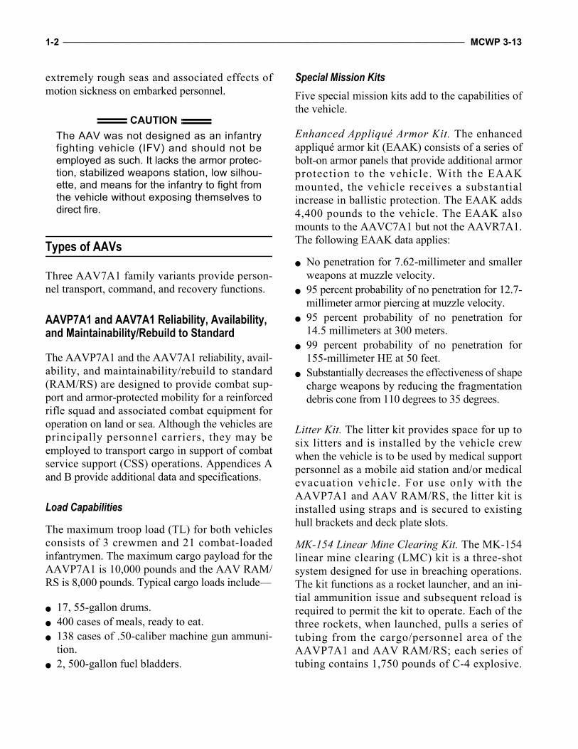
The AAVP7A1 and the AAV7A1 reliability, avail-ability, and maintainability/rebuild to standard(RAM/RS) are designed to provide combat sup-port and armor-protected mobility for a reinforcedrifle squad and associated combat equipment foroperation on land or sea. Although the vehicles areprincipally personnel carriers, they may beemployed to transport cargo in support of combatservice support (CSS) operations. Appendices Aand B provide additional data and specifications.
Load Capabilities
The maximum troop load (TL) for both vehiclesconsists of 3 crewmen and 21 combat-loadedinfantrymen. The maximum cargo payload for theAAVP7A1 is 10,000 pounds and the AAV RAM/RS is 8,000 pounds. Typical cargo loads include—
17, 55-gallon drums. 400 cases of meals, ready to eat. 138 cases of .50-caliber machine gun ammuni-tion.
2, 500-gallon fuel bladders.
Special Mission KitsFive special mission kits add to the capabilities ofthe vehicle.
Enhanced Appliqué Armor Kit. The enhancedappliqué armor kit (EAAK) consists of a series ofbolt-on armor panels that provide additional armorprotection to the vehicle. With the EAAKmounted, the vehicle receives a substantialincrease in ballistic protection. The EAAK adds4,400 pounds to the vehicle. The EAAK alsomounts to the AAVC7A1 but not the AAVR7A1.The following EAAK data applies:
No penetration for 7.62-millimeter and smallerweapons at muzzle velocity.
95 percent probability of no penetration for 12.7-millimeter armor piercing at muzzle velocity.
95 percent probability of no penetration for14.5 millimeters at 300 meters.
99 percent probability of no penetration for155-millimeter HE at 50 feet.
Substantially decreases the effectiveness of shapecharge weapons by reducing the fragmentationdebris cone from 110 degrees to 35 degrees.
Litter Kit. The litter kit provides space for up tosix litters and is installed by the vehicle crewwhen the vehicle is to be used by medical supportpersonnel as a mobile aid station and/or medicalevacuation vehicle. For use only with theAAVP7A1 and AAV RAM/RS, the litter kit isinstalled using straps and is secured to existinghull brackets and deck plate slots.
MK-154 Linear Mine Clearing Kit. The MK-154linear mine clearing (LMC) kit is a three-shotsystem designed for use in breaching operations.The kit functions as a rocket launcher, and an ini-tial ammunition issue and subsequent reload isrequired to permit the kit to operate. Each of thethree rockets, when launched, pulls a series oftubing from the cargo/personnel area of theAAVP7A1 and AAV RAM/RS; each series oftubing contains 1,750 pounds of C-4 explosive.
CAUTIONThe AAV was not designed as an infantryfighting vehicle (IFV) and should not beemployed as such. It lacks the armor protec-tion, stabilized weapons station, low silhou-ette, and means for the infantry to fight fromthe vehicle without exposing themselves todirect fire.

Employment of Amphibious Assault Vehicles ________________________________________________________________ 1-3
Upon detonation, the system is capable of open-ing a 100-meter long, 16-meter wide lane, at95-percent proof, through the minefield.
Winterization Kit. The winterization kit helps thevehicle operate in temperatures to -45 degreesFahrenheit. The kit consists of an engine coolantheater, winterization personnel heater, and batterybox heat exchanger.
Visor Kit. Used when the AAV is operated underextreme cold weather conditions, the visor kit pro-tects the driver from the elements and provides agreater field of vision. The kit consists of a visor,windshield wiper and motor, defroster hose, andattaching hardware. The visor kit may be installedon the driver’s hatch opening of AAV7A1 andAAV RAM/RS variants.
Communications The AAVP7A1 and AAV RAM/RS are equippedwith single-channel ground and airborne radiosystems (SINCGARSs) for use by the crew andembarked infantry commander. A vehicle inter-communications system provides the capabilityfor the crew and infantry commander to passinformation while the vehicle is in operation.
Firepower AAVP7A1 and AAV RAM/RS vehicles areequipped with the up-gunned weapons station(UGWS) that mounts an M2, .50-caliber, heavy-barreled (HB) machine gun and an MK-19,40-millimeter grenade launcher. The UGWS pro-vides an effective mix of firepower for offensiveand defensive requirements.
AAVC7A1As the command and control (C2) variant of theAAV7A1 family, the AAVC7A1 is employed bythe supported unit at the battalion and regimentalheadquarters level as a mobile command echelon/fire support coordination center (FSCC). The
AAVC7A1 is not configured for the AdvancedField Artillery Tactical Data System.
CommunicationsThe AAVC7A1 is equipped with six very high fre-quency (VHF), one ultrahigh frequency (UHF), andone high frequency (HF) radio transmitters andreceivers to allow secure communications with sub-ordinate, adjacent, and higher units, as well as withsupporting arms and logistic agencies. It includesworkstations for up to five staff officers and fiveradio operators. The AAVC7A1 intercommunica-tions assets provide the embarked commander andstaff with the capability to communicate with eachother while stationary or moving and to remotelyoperate radio assets from staff positions within thevehicle . Appendix C provides addi t ionalAAVC7A1 technical data and specifications.
FirepowerWhile the AAVC7A1 is not an offensive weap-ons system, it is equipped with the current 7.62-millimeter machine gun for self-defense.
AAVR7A1The AAVR7A1 is the maintenance and recoveryvariant of the AAV7A1 family. It is organic tothe AA company and battalion as well as themaintenance battalion of the force service supportgroup (FSSG). The AAVR7A1 supports vehiclerecovery and maintenance in the field throughthird echelon.
Capabilities The principal equipment of the AAVR7A1includes a hydraulic, telescoping, boom cranewith a 6,000-pound capacity, 30,000-poundcapacity recovery winch, as well as cutting,welding, and other portable maintenance equip-ment. Appendix D provides additional technicaldata and specifications.

1-4 ______________________________________________________________________________________________________ MCWP 3-13
Firepower Although the AAVR7A1 is not an offensiveweapons system, it is equipped with the current7.62-millimeter machine gun for self-defense.
Organization
AA units are organized and equipped to land thesurface assault elements of the LF and theirequipment in a single lift from assault shippingduring amphibious operations to inland objec-tives and to conduct mech operations and relatedcombat support in subsequent operations ashore.In addition, AA units can conduct shore-to-shoreassault operations, riverine operations, sea con-trol operations in littoral areas, and other mis-sions in support of Marine air-ground task force(MAGTF) operations. AA units may be tasked-organized as a maneuver element for riverineoperations and operations in littoral areas for theconduct of rear area security. These varied mis-sions reflect the flexibility and operational utilityof the AAV on the modern battlefield.
Assault Amphibian Battalion
The AA battalion is assigned to a Marine divi-sion. The battalion and/or its subordinate unitsare attached to or placed in support of a GCEcommander to provide ship-to-shore lift of thesurface assault elements of the LF. Once ashore,the battalion provides tactical mobility and com-munications to the supported force. The AA bat-talion augments the AA company’s organiclogistic capability by providing personnel, medi-cal, resupply, and overflow second and third ech-elon maintenance. Although primarily employedto mechanize the surface assault elements of aregimental landing team (RLT), AA battalion ele-ments may be employed in a CSS role forward ofthe forward edge of the battle area (FEBA) or inthe beach support area. The AA battalion has thecommand, staff, and resources necessary to planand execute mech operations as a maneuver con-trol headquarters when augmented with combat,
combat support forces, and FSCC representa-tives (i.e., air officer, naval guns liaison officer,81-millimeter mortar forward observers [FOs],and artillery FO).
The I Marine Expeditionary Force (MEF) and IIMEF each have a full AA battalion. The III MEFpossesses one AA company that is part of the unitdeployment program. This program is sourcedfrom I MEF. Marine Corps Forces Reserve hasone AA battalion (minus) consisting of two linecompanies and one headquarters and service(H&S) company.
Assault Amphibian Battalion, Headquarters and Service Company
The H&S company, AA battalion, provides the AA battalion commander the means to effect C2 of the battalion. Through its subordinate platoons and sections, the H&S company provides mainte-nance, communications, administrative, medical, supply, and other service support functions to the AA battalion. See figure 1-1.
Headquarters PlatoonThe headquarters platoon includes the medical,chaplain, and headquarters sections as well as thecompany staff.
Medical Section. The medical section includesmedical personnel organic to the battalion. Inaddition to their medical qualifications, these per-sonnel are familiar with the capabilities and limi-tations of the AAV. Section personnel provideadvice on the employment of AAVs as mobileaid stations and casualty evacuation vehicles andoperate the vehicles in support of such missions.
Chaplain Section. The chaplain section is respon-sible for the spiritual welfare of the battalion.
Headquarters Section. The headquarters sectioncontains those assets associated with the AA bat-talion staff functions, e.g., manpower staff officer(S-1)/communications and information systemsofficer (S-6).

Employment of Amphibious Assault Vehicles ________________________________________________________________ 1-5
Company Staff. In addition to exercising com-mand over H&S company, the company staff con-ducts functions associated with supporting andcoordinating personnel, logistics, and trainingrequirements for personnel attached to the H&Scompany. The company staff also exercise com-mand functions over the general support (GS) pla-toon and mobility, countermobility (M/CM)platoon when it is located at the battalion level.
General Support PlatoonThis unit is composed of a GS section and a com-mand, control, and communications section.
General Support Section. Composed of nineAAVP7A1s organized into three sections of threevehicles, the GS section provides support to thebattalion logistic trains.
Command, Control , and CommunicationsSection. Composed of six AAVC7A1 communica-tion vehicles and three AAVP7A1 chase vehicles,
the command, control, and communicationssection supports the C2 requirements of the AAbattalion and supported GCE maneuver units.
Mobility/Countermobility Platoon
The M/CM p la toon i s c o m p o s e d o f 2 4AAVP7A1s with 12 MK-154 LMC kits that aredivided between the MK-154 section and theobstacle clearing detachment. The mission of theM/CM platoon is to land combat engineer ele-ments from ship-to-shore or from shore-to-shoreto support the breaching of beachhead defensesand provide M/CM support to subsequent opera-tions ashore.
Motor Transport Platoon
The motor transport platoon is responsible for theoperation and maintenance of wheeled vehicles inthe battalion except those assigned to the AAcompanies.
SupplyPlatoon
MedicalSection
ChaplainSection
Command,Control, and
CommunicationsSection
CompanyStaff
H&SCompany
MaintenancePlatoon
CommunicationsPlatoon
HeadquartersPlatoon
HeadquartersSection
General SupportPlatoon
General SupportSection
ObstacleClearing
Detachment
MK-154Section
Motor TransportPlatoon
Mobility/Countermobility
Platoon
Figure 1-1. H&S Company.

1-6 ______________________________________________________________________________________________________ MCWP 3-13
Communications Platoon The communications platoon installs, operates,and maintains the communication system for thebattalion headquarters. The platoon is responsiblefor repairs through second echelon to communica-tions equipment organic to the battalion headquar-ters. In addition, the platoon supports the companycommunications sections as required.
Supply PlatoonThe supply platoon is organized to provide sup-ply support for organic battalion units.
Maintenance Platoon The maintenance platoon is responsible for thirdechelon maintenance of tracked vehicles in thebattalion. The maintenance platoon operates andmaintains the battalion’s two AAVR7A1s.
Assault Amphibian Company
The AA company consists of three line platoons,a headquarters platoon, and a maintenance pla-toon. See figure 1-2. Each of the line platoons has12 AAVP7A1s. The headquarters platoon pro-vides the company administrative and logisticsupport. The headquarters platoon includes the
headquarters section, command tractor sectionthat provides AAVC7A1 assets to the supportedunit headquarters, and GS section that providestactical mobility and logistic train assets to theAA company. The maintenance platoon providesthe AA company maintenance capability throughsecond echelon. The maintenance platoonincludes the AAV maintenance section, commu-nications section, and the retriever section thatmaintain the company’s AAVR7A1. The AAcompany may be reinforced with M/CM assetsfrom the AA battalion.
The AA company is usually employed to lift theassault elements of a reinforced infantry battal-ion. Whether attached or in direct support (DS)/GS, the AA company commander functions as aspecial staff officer in AAV employment. Infan-try and AAVs are task-organized to create a sin-gle tactical combat unit. The AA companycommander and subordinate commanders workin harmony with their supported unit counter-parts to achieve unity of command and effortaccording to the supported infantry commander’sconcept of operation. One or two of the AA com-pany’s AAVC7A1s along with chase AAVP7A1sare employed by the infantry headquarters to sup-port command echelon operations. The AA com-pany’s limited CSS capabilities, augmented by
MaintenancePlatoon
AAV MaintenanceSection
CommunicationsSection
RetrieverSection
HeadquartersPlatoon
HeadquartersSection
CommandTractor Section
General SupportSection
AA Company
AA Platoon AA Platoon AA Platoon
Figure 1-2. AA Company.

Employment of Amphibious Assault Vehicles ________________________________________________________________ 1-7
AA battalion resources, provide essential admin-istrative and logistic support.
Assault Amphibian Platoon
Organ i zed i n to fou r s ec t i ons o f t h r eeAAVP7A1s, the AA platoon normally conductsoperations attached to or in DS/GS of the infantrycompany. The AA platoon commander directsthe employment of the AA platoon according tothe supported unit commander’s concept of oper-ations. The AA platoon employs AAVs to—
Achieve mech mobility. Negotiate obstacles. Support the commander’s plan of fires. Enhance the commander’s communications capa-bility.
As a general employment guideline, AAVsexploit cover and concealment provided by ter-rain to reduce the risk of antiarmor attack. Toincrease the security of the AAVs, particularly inlimited visibility terrain, the vehicle should oper-ate with cargo hatches in the open-and-lockedposition to enable the embarked infantry to pro-vide added observation and fire protection.
Assault Amphibian Section
Organized with four AAVP7A1 vehicles, the AAsection provides combat support to the infantryrifle platoon. The AA section leader exercisestactical control (TACON) of AAVs under thecommand of the AA platoon commander. Thesection leader is responsible for the section’s firecontrol and responds to calls for fire from thesupported infantry commander. An AA sectionmay be used for transporting units (e.g., 81-milli-meter mortar platoon, engineer platoon).
Assault Amphibian Crew
The three members of the AA crew and vehicleprimarily support a reinforced infantry squad.The AA crewmen operate their vehicle under thedirection of the AA section leader.
Senior Crewman (Vehicle Commander or Crew Chief)Responsible for the employment of the AAV, thesenior member commands the AAV from theUGWS and employs the weapon systems.
Second Senior CrewmanAs the vehicle driver, the second senior crewmanoperates the vehicle at the direction of the seniorcrewman and in accordance with factors such asthe terrain, tactical situation, standing operatingprocedures (SOPs), and immediate action drills.
Third CrewmanThe third crewman is positioned in the vehicle tosupport the mission. When required, the thirdcrewman—
Serves as the assistant gunner. Supplies ammunition to the vehicle com-mander.
Maintains good order and discipline in thetroop compartment.
Warns of violations to the integrity of thewatertight hull.
Assists in embarking and debarking of theinfantry.
CAUTIONOnly qualified and licensed crewmen with amilitary occupational specialty (MOS) 1833 areallowed to operate the UGWS.

CHAPTER 2. OPERATIONAL PRINCIPLES
Command relationships in amphibious operationsshould help cooperative planning between the sup-ported infantry commander and the AAV com-mander/special staff officer to accomplish thespecified mission. The supported infantry com-mander and the AAV commander/special staffofficer must develop and train to the SOPs inher-ent to mech operations. The AAV commander/spe-cial staff officer must be involved with planningphases involving waterborne and ground move-ment to ensure the proper employment of the AAVunit. Once the commander’s intent is established,the AAV commander/special staff officer will pro-vide valuable guidance on the maneuver/employ-ment of the AAV unit based on the capabilitiesand limitations of the AAV unit in relation to theweather, enemy, and terrain. During operations,AAVs can support in DS or GS.
DS is a mission requiring a force to supportanother specific force and authorizing it to answerdirectly to the supported force’s request for assis-tance. The supported infantry unit maintains opera-tional control (OPCON). DS is the dominantcommand relationship for AAV units in support ofinfantry units.
GS is support given to the supported force as awhole, not to a particular subdivision of thatforce. When in GS, the AAV unit maintainsOPCON over its own unit and responds to sup-port requests equally. GS is typically in large-scale amphibious operations that require AAVs toconduct multiple lifts.
Command Relationships
To maximize the capabilities of the AAV unit,the supported infantry commander should inte-grate the AAV unit and establish cohesive work-
ing command relationships. Keeping the lines ofcommunications open will help C2 and foster theone-team, one-fight ethos. The command rela-tionship options available to the supported unitcommander include OPCON and administrativecontrol (ADCON). In some situations, the sup-ported infantry unit is responsible for logisticalsupport for the attached AAV unit. Normally, aninfantry company is not equipped to logisticallysupport an AAV platoon. Hence, AAV units areseldom attached to units below the infantry bat-talion level. In most cases, an AAV platoon isattached to a battalion landing team (BLT) and isin DS of one of the infantry companies (mechinfantry company).
Operational Control
The supported unit operationally controls theAAV unit. OPCON does not include authorita-tive direction for logistics or matters of admin-istration, discipline, internal organization orunit training.
Administrative Control
The supported unit administratively controls theAAV unit.
Assault Amphibian Battalion
A separate battalion organic to the Marine divi-sion, the AA battalion possesses the assets tomechanize one infantry regiment or parts of multi-ple regiments. The AA battalion commanderserves as a special staff officer to the commandinggeneral of the Marine division and directs themaintenance and logistic efforts of the battalion tosupport operations and on-order missions. The AAbattalion has the ability to function as a maneuverelement headquarters when provided augmentationfrom higher headquarters for FSCC positions (i.e.,

2-2 ______________________________________________________________________________________________________ MCWP 3-13
air officer, naval gunfire [NGF] liaison officer,FOs, and fire support coordinator [FSC]).
Assault Amphibian Company
When the AA company is attached to anotherorganization or given a support mission, the AAcompany commander works directly for the com-manding officer of the supported unit and becomesa special staff officer to the supported infantrycommander. When the company is 80 percenttask-organized with the infantry, the AA companycommander will directly command the remaining20 percent of the company’s assets. The com-mander’s primary duties include simultaneouslydirecting the maintenance and logistics supportorganic to the AA company and advising the sup-ported commander on the employment of AAVs.
Assault Amphibian Platoon
When the AA platoon is attached to anotherorganization or given a support mission, the AAplatoon commander works directly for the sup-ported company commander. In mech opera-tions, the supported commander is normally theinfantry, tank company or battal ion com-mander. Based on mission, enemy, terrain andweather, troops and support available—timeavailable (METT-T), the supported commandermay be from another combat support unit orCSS service unit (e.g., AA platoon participatingin foreign humanitarian assistance [FHA]/disas-ter relief operations).
The supported commander is collocated with theAA platoon commander in the command vehiclefor ease of C2. Normally, the AA platoon com-mander occupies the AAV turret, while the sup-ported commander is positioned in the hatch of thetroop commander (TC). As the senior AA officerassigned to a battalion, the platoon commanderserves as a special staff officer to the battalioncommander and advises the supported com-mander on the tactical employment of AAVs. TheAA platoon commander directs the platoon’s
movement according to the supported com-mander’s intent. During movements, the AA pla-toon commander maintains the TACON of the AAplatoon and the individual employment of AAVs.
Assault Amphibian Section
The AA section leader is responsible to the AAplatoon commander for the maintenance andreadiness of the platoon’s AAVs. The sectionleader occupies the AAV turret with the sup-ported infantry platoon commander occupyingthe TC’s hatch. In addition to duties similar tothat of the AA platoon commander, the sectionleader serves as a focal point for rapid dissemina-tion of the AA unit SOP to infantry platoon com-manders and helps the infantry and AAV crewsform into a cohesive team. The section leader isalso the focal point for employing the AA sec-tion’s weapons systems.
Task Organization
The Marine Corps is one of the few armed forcesin the world that conducts mech operations withtemporarily formed units of light infantry andarmor/antiarmor units. These well-trained, gen-eral-purpose infantry units are capable of execut-ing air assault, mech or other ground combatoperations. The predominant method of employ-ing AA units is through task organization, bywhich an AA unit possessing the required quan-tity and mix of assets is attached to the battalionand in DS/GS of the supported unit.
In mech operations, the AA unit provides theinfantry commander with a ready pool of exper-tise and experience to assist in the accomplish-ment of the assigned mission. The establishedAA tactical organization, the AA unit leaders’experience and familiarity with the unit’sstrengths and weaknesses, and the establishedSOP provide the infantry commander with thetactical and logistical requirements for move-ment of embarked infantry.

Employment of Amphibious Assault Vehicles ________________________________________________________________ 2-3
To maximize the capabilities of the AAV and itscrew, the supported unit should quickly integratethe AA unit, establish close working relationshipsat peer levels, and keep communications openbetween the supported unit and the supportingunit. The level of success or failure that the mechforce will achieve is greatly dependent on the teamconcept, level of cooperation, and mutual trust.
Fundamentals
The process of task organization distributes avail-able units to a supported headquarters by estab-l i sh ing va r i ous command and suppo r trelationships. A mechanized task force (MTF) iscreated by task-organizing mech infantry and/ortanks under the command of a single battalion orregimental commander. Air, artillery, lightarmored reconnaissance (LAR), motor transport,and other combat support and CSS units supportthe MTF. The following fundamentals apply totask organization:
Flexibility—Task organization is based on thecurrent situation but must also be prepared tomeet new requirements due to rapidly chang-ing events. The task-organized elements of aunit should have a similar degree of mobility.
Unity of command—Mech forces normallyoperate at distances and a tempo that precludecentralized control of supporting units by theparent headquarters. To ensure positive con-trol and unity of effort, supporting units shouldbe attached to the base maneuver units. Thecommander must have the means and authorityto control the employment of the combinedarms force. Command and support relation-ships must provide the commander maximumflexibility to accomplish the assigned mission.To develop familiarity, teamwork, and trust
within subordinate units, the commandershould avoid making frequent changes to thetask organization and strive to establish stand-ing relationships among units.
Self-sufficiency—Because subordinate unitsare highly mobile and may operate at consider-able distance from one another, the highercommander should also assign sufficient com-bat support and CSS to accomplish the mission.
Tactical integrity—To facilitate and simplifyC2, the commander should maintain the tacticalintegrity of units when task-organizing. Main-taining tactical integrity of combat supportunits is secondary to the tactical integrity ofcombat units.
Cross Attachment
Task-organizing a force for a specific mission ona temporary basis creates cross attachment. Forexample, a tank battalion detaches a tank com-pany that is subsequently attached to an infantrybattalion mechanized in AAVs. The infantry bat-talion mechanized in AAVs detaches a companyto the tank battalion to create two battalion taskforces with complementary capabilities. Cross-attached units are described by their mix of tankand mech infantry.
Tank HeavyA tank-heavy force has more subordinate tankunits than infantry units. See figure 2-1 on page2-4. The headquarters of a tank-heavy task forceis usually that of a tank battalion. Tank-heavyforces are preferred when—
Shock action and firepower are desired. Terrain is open with few obstacles. Enemy antitank (AT) fire is easily suppressed.

2-4 ______________________________________________________________________________________________________ MCWP 3-13
Mech HeavyA mech-heavy force, also known as infantry-heavy force, has more subordinate infantry unitsmounted in tracked vehicles [AAVs] than subor-dinate tank units. See figure 2-2. The headquar-ters of a mech-heavy task force is usually that ofan infantry battalion or regiment. Mech-heavyforces are employed—
In the conduct of security operations suitablefor LAR or mech infantry.
When specific terrain must be seized and held. In built-up areas or other restrictive terrain. When visibility is limited. Against strong points. When heavy AT fires or obstacles are expected.
BalancedA balanced force has an equal number of subordi-nate tank and mech infantry units. The headquar-ters of a balanced task force can be either that ofa tank battalion or infantry battalion/regiment. A
balanced task force enhances tank and infantrycapabilities while retaining similar mobility.
Company-Size ManeuverA company-size maneuver element is a teamorganized by cross attachment of one or moretank platoons and/or mounted or dismountedinfantry platoons. An infantry or tank battalioncommander receiving tank or mech infantrycompanies based on METT-T may tailor thoseunits by cross-attaching tank platoons and mechinfantry companies to form company teams. Thecompany is the smallest element of a mech forcetask-organized with combined arms. A com-pany-sized mech unit typically consists of a tankor infantry headquarters; a combination of sev-eral tank, infantry, and/or LAR platoons; and anattached AA unit supporting the infantry. Othersupporting units, such as combat engineers, mayalso be attached. The following are types ofmech company teams:
Tank-heavy teams. Mech-heavy teams. Balanced teams. Mech-pure companies. Tank-pure companies.
Combat Support
In carrying out their mission of supporting theinfantry, AA units typically receive combat sup-port from various units. These combat supportunits may be attached, GS/DS or organic to thesupported unit. Support will come from the GCEand other elements of the MAGTF, including theaviation combat element. The types of combat sup-port provided will depend on METT-T.
AntiarmorAntiarmor support is provided by tube-launched,optically-tracked, wire-command link guidedmissile (TOW) sections and Javelin sections ofthe antiarmor platoon located in the infantry bat-talion weapons company. The tank battalionmaintains an AT platoon equipped with TOWs
Figure 2-1. Tank-Heavy Force.
Figure 2-2. Mech-Heavy Force.

Employment of Amphibious Assault Vehicles ________________________________________________________________ 2-5
mounted on a high mobility multipurposewheeled vehicle (HMMWV).
TOW. The TOW is used to engage enemy armorat ranges up to 3,750 meters and assigned mis-sions to overwatch lead units or to cover flanks.HMMWV-mounted TOWs do not possess thesame cross-country mobility as the AAV, tank orLAV. Because TOWs are vulnerable to suppres-sive fires, firing positions must be camouflagedto take advantage of the TOW’s long firing rangeand to conceal the vulnerable TOW shooter.
Javelin. The Javelin is the replacement for theDragon antitank guided munition (ATGM). It is atop-attack or direct-fire mode, man-portable, ATmissile. The Javelin’s lock-on-before-launch,fire-and-forget capability increases the probabil-ity of a hit because the gunner is not exposed toenemy suppressive fires while tracking the mis-sile to its target. The Javelin’s maximum effec-tive range of 2,000-plus meters is beyond themaximum effective range of current threat tankand combat vehicle coaxial machine guns. TheAAV provides the embarked infantry carryingthese systems with mobility and limited armoredprotection.
81-Millimeter MortarThe 81-millimeter mortar of the weapons companyof the infantry battalion provides an ability todeliver immediate suppressive fires or target mark-ing. Mortar squads may depend upon AAVs fortransport during mech operations. Because of theirlimited range, mortar squads are usually placedwell forward in the vehicle formation. If the entiremortar platoon is assigned, the two sections willbound to alternating firing positions to keep thelead elements of the force within their firing fan. Ifonly one section is available, it will normallyestablish a firing position when required. Thisallows the fires of the section to be massed.
Heavy Machine GunsThe infantry battalion weapons company’sMK-19, 40-millimeter grenade launcher and M2,
.50-caliber machine gun are normally employedin security missions and can provide direct firesupport to dismounted infantry. When mountedon transport vehicles, the M2 and MK-19 can beused in the conduct of route reconnaissance.AAVs can also provide direct fire support withthe M2 and MK-19 machine guns in the vehi-cles’ UGWS.
ArtilleryArtillery is the primary supporting arm for landoperations. It provides most of the suppressive firethat allows assaulting elements to maneuver. Avariety of projectiles (e.g., HE, smoke, illumina-tion, chemical, dual purpose improved conven-tional munitions [DPICM], laser-guided munitions[Copperhead]) are available. The DPICM andCopperhead rounds have an antiarmor capability.FO teams from supporting artillery batteries origi-nate calls for fire. In the absence of FO teams,AAV crews can call for and adjust artillery fires.Because towed artillery cannot displace as rapidlyas the mech force, artillery must echelon firingunits forward to provide continuous coverage foran advancing mech force. The artillery FO sup-porting the mech force should maintain close coor-dination to determine the exact status of artillerysupport. If mech units advance while their support-ing artillery is displacing, early coordination withother supporting arms can potentially prevent gapsin fire support coverage.
Naval Gun Fire Although the MAGTF does not have an organicNGF capability in most amphibious operations,Navy ships will provide NGF support to theforces ashore. AAVs may have their own NGFliaison officer attached that will coordinate NGFfor the AAV unit or supported commander duringamphibious operations or during subsequentoperations that are conducted near the coastline.
ReconnaissanceGCE units provide reconnaissance support.Reconnaissance teams using organic assets areinserted by air or mech patrols of tanks and

2-6 ______________________________________________________________________________________________________ MCWP 3-13
AAVs/LAVs. Patrols will normally patrol forwardand to the flanks not to exceed the supportingarms umbrella provided by the MAGTF.
Combat EngineersEngineers conduct minefield breaching/emplace-ment and obstacle clearing/installation. To sup-port the task force, engineers should be providedAAVs for transportation to have the same mobil-ity as the maneuver elements. Combat engineersshould be well forward in the mech force if chokepoints, obstacles, and minefields are expected.
To rapidly breach minefields and obstacles, engi-neers use the MK-154, LMC kit, that is organic tothe H&S company, AA battalion. The MK-154 canbe mounted on any AAVP7A1. The kit is com-posed of three rocket-propelled line charges con-taining 1,750 pounds of C-4 plastic explosive thatis stored in the AAVP7A1 troop compartment. TheMK-154 can clear a lane 100 meters by 16 meters.When attached to the mech force, the chase vehi-cles assigned to the MK-154 provide added mobil-ity to breaching teams and combat engineers.
AntiairAir defense for the mech force is a multilayeredsystem. It includes long-range attack aircraft thatstrike enemy airfields and conduct combat airpatrols to intercept enemy aircraft and the low alti-tude air defense (LAAD) battalion. LAAD teamsusing the Stinger surface-to-air missile are posi-tioned around the force with overlapping sectors offire to provide defense against enemy aircraft.Although the LAAD teams have their own trans-port, they may be carried in AAVs to increase theirmobility to that of the mech force.
AirClose air support (CAS) is provided to the mechforce by both fixed- and rotary-wing aircraft.Rotary-wing aircraft allows overwatch of theMAGTF during mech operations and enhance sit-uational awareness of the battlefield.
AAV Allocations
Each AA battalion has at least four letter compa-nies and an H&S company. Each letter companyis equipped with 43 AAVP7A1s, 2 AAVC7A1s,and 1 AAVR7A1. The AAVs used to support theGCE come from the three line platoons of eachletter company. Each line platoon is equippedwith 12 AAVP7A1s.
Approximately 42 AAVs are required to mecha-nize a reinforced infantry battalion; however, theAA company possesses only 36 AAVP7A1s ded-icated for support. Table 2-1 shows the typicalnumbers of AAVs required to mechanize ele-ments of the GCE.
Table 2-1. AAV Allocation.
The AA company has 36 AAVP7A1s in 3 lineplatoons available for assignment to GCE units.Based on the mission and other transportationassets assigned, the GCE commander can assignfour additional AAVP7A1s to the GS section ofthe AA company headquarters platoon. Nor-mally, these vehicles provide support in towingdisabled AAVs to the maintenance collectionpoint for repair, support the company logistictrain, and provide local security to the AA com-pany headquarters.
The AA platoon is the basic building block fortask organization. Generally, no more than 18Marines should be assigned to any one vehiclesince more than this number requires precisestaging and seating arrangements that candegrade the ability of embarked personnel torespond to tactical situations. No more than 21Marines should be contemplated for ship-to-shore
UnitNumber
RequiredThree infantry companies (rein) 36 AAVP7A1s81-millimeter mortar platoon 8 AAVP7A1sEngineers 3 AAVP7A1sBattalion aid station (BAS) 3 AAVP7A1sCommand 2 AAVP7A1s
2 AAVC7A1s

Employment of Amphibious Assault Vehicles ________________________________________________________________ 2-7
movement. The established method of task orga-nization is one AA section for each rifle platoonand one AA section for support missions. Thesesupport missions include the command AAVused by the infantry company commander andthe AA platoon commander, logistic AAV, 60-millimeter mortar section, and engineer vehicle toprovide mobility for any other assets attached tothe company by higher headquarters.
Movement
Self-deploying AAVs allow the MAGTF tomaneuver forces from ship to shore and inland ina seamless transition. The AAV provides theprincipal means of armored-protected land andwater mobility for supported units.
Control
The AA unit movement is controlled throughcentralized and decentralized techniques.
CentralizedThe centralized control technique enables thesupported commander to control the movementof the mech force through verbal orders to theAA unit leader. This technique maximizes theexperience and skill of the AA unit to facilitatethe movement of the force. In addition, the cen-tralized control technique may be employed forthe conduct of tactical road marches or move-ment to contact when the unit is travelingtogether. Centralized control allows the supportedcommander to—
Coordinate fire support. Plan. Issue orders to assigned unit leaders. Conduct liaison with other units on the marchwhile retaining centralized control of theembarked force.
Decentralized ControlThe decentralized control technique passes con-trol of the movement of AA sections to subordi-nate leaders of the embarked force. For example,the infantry platoon commander would exercisethe control of movement through the supportingAA section leader. The AA section leaderreceives direction from the infantry platoonleader and controls the movement of the AAVs inthe section accordingly. This technique may beused in the following situations:
Upon initiation of contact. In the approach to the point of debarkation. When the mech infantry platoons are operatingaway from the main body.
Considerations
Dispersion, speed, possible immediate actions, andthe commander’s location to effectively control theunit should be considered when maneuveringforces. During movement, the commander should—
Use terrain to mask movement/noise and toavoid exposure to the enemy.
Use supporting arms to suppress enemy antiar-mor fires.
Move quickly out of the impact area whenencountering enemy indirect fire.
Change the AAV’s primary position afterengaging the enemy.
DispersionThe factors of METT-T greatly influence disper-sion and mobility. For example, when operatingin a traveling/column manner, a battalion-sizedMTF can occupy over 17 kilometers from front torear. Such an MTF cannot generate significantcombat power quickly. If the point elements haltand engage the enemy, it could take 30 minutesfor the remainder of the column to close the for-mation and join the fight. Commanders mustminimize the effects of this dispersion of combatpower. Having units maneuver on broader fronts

2-8 ______________________________________________________________________________________________________ MCWP 3-13
when the terrain permits can reduce the effects ofimproper dispersion.
Speed
Mech columns routinely travel at speeds aver-aging 20 miles per hour. A meeting engage-ment of two opposing mech forces can occur at40 miles per hour, and a single column canmove quickly into the opposing force’s antiar-mor kill zone without notice. Speed has the fol-lowing advantages:
Permits the rapid massing of combat powerfrom across a broad expanse of terrain at thedecisive point in the battle.
Supports the rapid exploitation of openingsin the enemy’s front, permitting the armor-protected movement of infantry into theenemy’s rear.
Permits the commander to maneuver forcesswiftly and place them on crucial sections ofthe battlefield, thereby forcing the opposingcommander to surrender the initiative.
Immediate ActionsThe individual training of AAV crews and infantrywill carry the first critical moments of the mech bat-tle, while the mech force continues to maneuver byeither advancing or seeking cover and concealmentfrom enemy fire. Immediate action drills of funda-mental responses to enemy actions must be war-gamed and rehearsed to the point where they can beconfidently carried out instantly. In mech opera-tions, the commander’s decisionmaking often is lim-ited to a matter of seconds, and actions are executedby the forces in less time than it takes the com-mander to assess the situation and decide on a spe-cific action.
Commander’s Location Normally positioned as far forward in the formationas feasible under the tactical situation, the MTF com-mander should position the command vehicle imme-diately behind the forward screening section ofAAVs, tanks or LAVs. From an overwatch position,the commander will be able to employ supportingarms and direct additional mech forces forward tothe developing tactical situation.
CHAPTER 3. AMPHIBIOUS OPERATIONS
During World War II, the amphibious and mechcharacteristics of the amphibious tractor made itthe backbone of the Marine Corps’ amphibiousassault capability. The landing vehicle, tracked,was originally designed to operate primarily inthe water and in a logistical role, but its demon-strated utility and versatility quickly led toimprovements that largely reversed its initial con-cept of employment. Continuous upgradesenhanced its inherent ability to transition from anarmored landing craft to an APC. Vast improve-ments were made to the vehicle’s mobility andfirepower ashore. These combined changes pro-duced the highly capable AAV that is a criticalpart of the Marine Corps’ amphibious doctrine.
Joint Publication (JP) 3-02, Joint Doctrine forAmphibious Operations, defines an amphibiousoperation as a military operation launched fromthe sea by an amphibious force, embarked inships or craft with the primary purpose of intro-ducing a landing force ashore to accomplish theassigned mission. Amphibious operations includeassaults, withdrawals, demonstrations, raids, andother operations in a permissive, uncertain orhostile environment.
The AAV7A1’s demonstrated ability to negoti-ate various surf conditions and obstacles whilesimultaneously withstanding small arms firemakes it uniquely suited to conducting the initialportion of any amphibious operation. These char-acteristics allow the Marine Corps the flexibilityto exploit gaps in the enemy’s coastal defensesand/or mass substantial combat power at a deci-sive place to create such gaps.
Once the enemy’s defenses have been pene-trated, the mech and highly mobile nature of theAAV enable the embarked assault forces to rap-idly deploy to their inland objective. This dual
nature of the AAV helps to generate an over-whelming operational tempo thus maintaining theoverall momentum of the assault.
Types of Operations
There are five principal types of amphibiousoperations—the assault, raid, demonstration,withdrawal, and other operations. Various capa-bilities and functions of AAVs provide supportfor these amphibious operations.
Assault
The amphibious assault is the most importanttype of amphibious operation. It involves estab-lishing a force on a hostile or potentially hostileshore for the immediate execution of inlandmaneuver. The unique combination of armor andamphibious capabilities of the AAV make it themainstay of surface assault forces conductingamphibious assaults.
Raid
An amphibious raid is a landing from the seainvolving swift incursion into hostile territory fora specified purpose that is followed by a plannedwithdrawal. Raids are conducted to—
Inflict loss or damage. Secure information. Create a diversion. Capture or evacuate individuals and/or material.
Raid forces consist of individuals or unit(s) withthe capabilities or skills required to accomplish themission. Raid forces should be as small as possi-ble to maximize stealth and speed and to achieve

3-2 ______________________________________________________________________________________________________ MCWP 3-13
the desired effect. AAVs should be used when themission requirements dictate the need for armor,firepower, and mobility. AAVs also have the abil-ity to extract the raid force back to sea without theassistance of additional landing craft.
Demonstration
The amphibious demonstration is conducted todeceive the enemy by a show of force with theexpectation of deluding the enemy into a course ofaction unfavorable to him. The effectiveness of ademonstration increases in direct proportion to thedegree of realism involved in its execution. TheAAVs’ imposing presence enhanced through theutilization of their smoke generation system andnoise signature makes AAVs a convincing show offorce. The amphibious and mech nature of theAAV pressures the enemy to divert forces to dealwith the threat, thus achieving the desired effect.
Withdrawal
The amphibious withdrawal involves the evacua-tion of land forces by sea in naval ships or craftfrom a hostile shore. Amphibious withdrawalsmay be conducted to extract a force under pres-sure, to assist in the repositioning of forces else-where in theater, to reconstitute forces afloat or toestablish a reserve after introduction of follow-onforces. The armored and amphibious nature ofAAVs makes them particularly well suited forwithdrawing forces from hostile shores. Theirself-sufficient amphibious capability enablesthem to act as a covering force for other assetswithdrawing aboard landing crafts air cushion(LCACs), landing crafts, utility (LCUs) or land-ing craft, mechanized (LCMs).
Military Operations Other Than War
Amphibious operations in support of MOOTWmay involve elements of both combat and non-combat operations. Some of these operations mayparallel other types of amphibious operations (e.g.,a noncombatant evacuation operation [NEO] mayclosely parallel an amphibious raid) and may
require minor adjustments to planning. OtherMOOTW (e.g., FHA) may require considerableflexibility on the part of the planners. MOOTWare normally more sensitive to political consider-ations due to the overriding goal to prevent, pre-empt or limit potential hostilities. In addition toflexibility of platform, amphibious and mech capa-bilities, and force protecting armor, AAVs have asubstantial cargo capacity to assist in conductingvaried operations ranging from NEOs to reliefoperations.
Intelligence Requirements
The impact of environmental conditions andenemy defenses must be considered when AAVsare employed, because AAVs are typically thefirst assault wave in amphibious operations. Intel-ligence information on hydrography and enemydefenses will be required to effectively employAAVs to negotiate the seaward approaches and tomove from the surf zone to inland objectives.
Hydrography
Hydrography, the description and study of bod-ies of water and their touching land areas, is usedto interpret sea, surf, and beach conditions onAAV employment. Many complex factors influ-ence these conditions and have varying effectsupon AAV operations. The success or failure ofan amphibious landing using AAVs largelydepends on the completeness and accuracy ofintelligence data and upon the AAV unit leader’sinterpretation of that data. Although sea, surf,and beach characteristics contribute to the fol-lowing AAV casualties, appendix E providesAAV recovery criteria:
Swamping, flipping or capsizing by breakerswhen approaching the shore.
Sinking due to structural damage sustained fromimpacting reefs or other natural obstructions.
Broaching on a sandbar, obstacles or the beach.

Employment of Amphibious Assault Vehicles ________________________________________________________________ 3-3
Sea States AAVs have a demonstrated ability to easily nego-tiate sea states 1 through 3 (see table 3-1), butwill experience difficulty maintaining speed andmaneuverability in sea state 4. AAVs can sur-vive operations in sea state 5, but at reducedeffectiveness. Troops should not be embarkedaboard AAVs in sea state 5 conditions, and it isnot advisable to conduct operations in sea state 5or greater.
Sea WavesCaused by high winds in storm areas, sea wavesare usually steep, have a short period, and oftencrest and break in deep water. They are com-monly referred to as white caps or combers ifvery large. Combers affect the speed and maneu-verability of the AAV. In addition, the driver’svisibility will be reduced because of the sprayencountered. Operations in sea states 3 to 5should be conducted with the driver’s hatchclosed to enable the driver to maintain speed. Inthese conditions, the vehicle commander, mag-netic heading device or precision lightweight glo-
bal positioning system (GPS) receiver system(PLGRS) may be used to assist the driver inmaintaining course. High seas must be antici-pated in the navigation plan, landing formation,and landing schedule.
Swell A swell is characterized by its lack of steepnessand longer, rolling period. Depending on theirsize and orientation to the AAV, swells canimpede the vehicle’s speed and maneuverability.Swell conditions must be anticipated in the navi-gation plan, landing formation, and landingschedule. Heavy swells (sea state 5 or greater)may also make debarkation from naval shippingmore difficult or dangerous. Swells more com-monly affect embarked personnel by causingmotion or seasickness and fatigue. Long water-borne movements (greater than 15,000 yards) inlarge swells (sea state 4 or greater) should beavoided as they reduce the combat effectivenessof embarked assault forces. Swells have thegreatest effect upon AAVs once they reach theshore and form breakers.
Table 3-1. Sea State Conditions.
Sea State Conditions
1Wind speeds between 5 to 9 miles per hour (5 to 8 knots).Wave heights considered small wavelets between 0.5 and 1 feet (0.6093 to 0.304 meters.Small wavelets with glassy-appearing crests and no breaking.
2Wind speeds between 10 to 11 miles per hours (9 to 10 knots).Wave heights considered large wavelets, between 1.5 and 2 feet (0.456 to 0.609 meters).Large wavelets, crests begin to break and whitecaps are scattered.
3Wind speeds between 16 to 17 miles per hour (14 to 15 knots).Wave heights considered small, between 3.5 and 4 feet (1.06 to 1.21 meters).Small waves becoming longer and whitecaps are numerous.
4Wind speeds between 19 to24 miles per hour (17 to 21 knots).Wave heights considered moderate, between 4 and 7.5 feet (1.24-2.5 meters).Moderate waves forming numerous white caps and some spray.
5Wind speeds between 24 to 28 miles per hour (21 to 25 knots).Wave heights considered large, between 8 and 12 feet (2.43 to 3.65 meters).Large waves form and whitecaps are common, along with more spray.

3-4 ______________________________________________________________________________________________________ MCWP 3-13
TidesThe stage of tide affects the width of the beach andsurf zone; therefore, in amphibious operationsusing AAVs, the high and low tides and the tiderange must be known. Tides affect the type of surf,depth of water over sandbars and reefs, and theeffectiveness of underwater obstacles. For exam-ple, high tides will enable AAVs to more easilyovercome sandbars, reefs, and obstacles but maytend to increase the percentage of plunging break-ers by shortening the surf zone. Low tides mayhave the direct opposite effect by increasing spill-ing breakers. Extreme highs and lows, which mayremain unchanged over the course of several days,can occur and severely affect operations.
Surf Various factors can greatly affect amphibiousoperations using AAVs in the surf zone. The min-imum information on the surf conditions neededto safely conduct AAV operations should includethe following:
Significant breaker height. Maximum breaker height. Breaker period or interval in seconds. Breaker types (i.e., spilling, plunging or surging). Breaker angle. Littoral or long shore current in knots. Width of the surf zone. Number of breaker lines.
Before AAV operations, a surf observation report(SUROB) must be conducted. For large-scaleoperations, the SUROB should be conductedhourly for 4 hours before H-hour.
Surf ZoneThe most dangerous portion of an amphibiouslanding is negotiat ing the surf zone. Theenergy of the wave is released at this point andmost landing craft casualties occur at this time.Conditions in the surf zone are the combinedresult of the following factors:
Breaker type. Maximum breaker height.
Breaker period or interval. Vehicle load.
Table 3-2 illustrates the handling capabilities andsafety criteria of the AAV under various condi-tions. This table represents the maximum safebreaker heights and breaker periods allowed foreach type of AAV load. Exceeding these condi-tions is unsafe for AAV operations.
The load criteria is based on three internal cargoweights that act as a type of ballast for the AAV:combat load (CL) 10,000 pounds; TL 5,600pounds; and combat equipped (CE), which is anempty vehicle. The vehicle can handle shorterintervals between breakers or right itself as thecargo or ballast increases. The listed breaker periodshould be read as the minimum interval in seconds.
Narrow surf zones can hinder AAV operations ifthe surf is high (4 to 6 feet) and moving in excess
Table 3-2. Safe Breaker Heights andBreaker Periods.
Type of AAV Load
Maximum BreakerHeight (feet)
Breaker Period(seconds)
100 Percent Plunging Breakers
CL 610*
9 9*
TL 6 10*
9 9*
CE 6 8*
13 13*
50 Percent Plunging/50 Percent Spilling Breakers
CL 6 8
TL 6 8
CE 6 10
100 Percent Spilling Breakers
CL 6 5
TL 6 5
CE 6 7
* Used when planning combat operations.

Employment of Amphibious Assault Vehicles ________________________________________________________________ 3-5
of 8.5 knots. These combined conditions cancause the vehicle to contact the bottom quicklyand sometimes violently, become swamped, andflip over.
Reefs, Sandbars, and Other Natural Obstructions A distinct advantage AAVs have over conven-tional landing craft is their tracked suspension.This alone enables them to negotiate reefs, sand-bars, and other natural obstructions that mayimpede boats. The surf beat, vertical climb, andbreakers must be considered before AAVs arenavigated through those obstructions. Informa-tion needed for AAV operations over reefs orbars should include the following:
Nature or type of the obstruction. Distance offshore or location of the obstruction. Slope (seaward). Depth of water at various tidal stages or heightof obstruction above water.
Gaps or passages in the sandbar, reef orobstruction.
Breaker height.
Surf Beat. Surf beat is the distinct rise and fall ofthe mean water level within the surf zone. Surfbeat can be of significance to AAVs approachingsubmerged obstacles such as sandbars or reefs.Normally, surf beat is equal to 10 percent of thebreaker height. This quick raising and dropping ofalmost a foot at times can throw an AAV against areef hard enough to severely damage the suspen-sion, because reefs can be composed of coral orrock. The damaging effects of surf beat upon avehicle can be overcome if the tide provides suffi-cient water depth over the obstacle or if the com-position of the sandbar or reef is soft material.
Vertical Climb. On land, AAVs can climb a 3-foot wall, but in water, the vertical distance ismuch less. The depth of the water over a steepgradient obstruction (e.g., reef, sea wall) shouldbe at least 3 feet to allow the tracks to be able toengage and climb it. This is not a concern wherethe gradient is less steep (e.g., sandbars), since
the tracks will eventually contact the bottom andgain traction to transverse the obstacle. Becausereefs are irregular and often contain many pock-ets or holes, care should be taken to avoid get-ting an AAV stuck in one without sufficientwater depth to climb out.
Breakers. Despite the AAV’s ability to climbsandbars and reefs, additional care should betaken whenever approaching these obstacles asswells may break violently upon them. Whereverbars or reefs are present, the wave crest will peakas the waves roll over them. The water depth overthe sandbar or reef and the wave height determinewhether or not breaking takes place on or near theobstruction. Generally, if the depth is less thanone and a half times the breaker height, waveswill break upon the sandbar or reef. For exam-ple, a 6-foot swell will break upon a sandbar orreef unless the water depth over that obstructionis a least 9 feet.
Currents In conducting amphibious landings, planners aremost often concerned with the effects of longshore or littoral current, but offshore seasonalcurrents can have a greater effect on AAVs. Inconducting AAV operations, the speeds of longshore (littoral) and offshore currents should becollected and considered.
Offshore Currents. Tidal and nontidal offshorecurrents are found outside the surf zone. Cur-rents in excess of 3 knots will adversely affect anAAV’s navigation and speed.
Long Shore/Littoral Currents. Littoral currentsare set up within the surf zone by the breakingwaves. They flow parallel to the shoreline insidethe breaker line. They increase with larger breakerangles, beach gradients, and breaker heights.Larger intervals between breakers tend to slow thevelocity of littoral currents. These currents presentlittle problem for AAVs since the vehicles haveusually gained positive traction before reachingthe point where they occur. These currents cancause conventional landing craft to broach along

3-6 ______________________________________________________________________________________________________ MCWP 3-13
the shoreline. At this point, AAVs are out of thesurf zone and past the high watermark.
GradientGradient tends to have little effect upon AAVoperations unless it is nearly vertical. Depth of thesurf zone, number of breakers present, and type ofbreaker that will be encountered are gradientcharacteristics that may affect AAV operations.Steep gradients of more than 1:15 (7 percent) tendto produce a very high percentage of plungingbreakers. Steep beaches normally have short surfzones with one line of breakers present. Moder-ate gradients of between 1:15 (7 percent) and 1:30(3 percent) tend to produce spilling breakers, butoften create a mixed percentage of both plungingand spilling breakers. Moderate gradients pro-duce bars and extend the surf zone creating two tofour lines of breakers. Mild gradients of greaterthan 1:30 (3 percent) tend to produce a very highpercentage of spilling breakers. They also pro-duce several bars that greatly extend the surf zoneand lines of breakers.
Beach Composition
The beach may be composed of silt, mud, sand,gravel, boulders, rock, coral or any combinationof these. The nature and composition of the beachforeshore, backshore, and hinterland may affectthe trafficability for AAVs.
Foreshore. Coarser materials (i.e., gravel, rocksor cobblestones) from the surf zone to the highwatermark provide poor traction for AAVs begin-ning to ground themselves and moving out of thewater. Since AAVs are not fully grounded at theforeshore, they tend to slip on these coarse mate-rials. The heavier the AAV and the steeper thegradient, the less traction an AAV will get. Themost critical area of trafficability on the beach isthe foreshore due to the increased gradient andlooseness of the material. As the gradient
increases to its peak, AAVs will tend to becomestuck or mired in the loose bottom material.
Backshore. The composition of the backshore isusually soft, loose, and dry. Normally, the back-shore does not present a problem to trafficabilitysince it generally has a mild gradient, but AAVsmay lose traction if the gradient is steeper.
Hinterland. The hinterland is the area just pastthe backshore behind the first line of permanentvegetation. AAVs may encounter trafficabilityproblems in the hinterland if confronted withdunes or cliffs. If these obstacles are too steep,the AAV may advance only to the backshore.
Beach Exits Avenues off the beach or beach exits allowAAVs to quickly move inland. Natural or man-made obstacles may channel or prevent AAVsfrom exiting the beach to move inland. The AAVcan climb a 3-foot wall and cover an 8-foot span,but any obstacle greater than this must bebreached or avoided.
Enemy Defenses
Amphibious operations will normally avoid con-centrated enemy defenses or surfaces. The LFwill require the armored, amphibious capabilitiesof the AAV. Enemy defenses against AAV land-ings can vary from AT mines and tetrahedrons toentrenched infantry with ATGM or a combina-tion thereof. Operational considerations for usingAAVs are the enemy situation and obstacles.
Enemy SituationEnemy situation intelligence required when plan-ning AAV landings includes—
Tank and IFV threat. ATGM threat. Heavy machine gun (above 12.5 millimeters)threat.

Employment of Amphibious Assault Vehicles ________________________________________________________________ 3-7
Hardened positions (e.g., bunkers, trenches). Enemy capability to observe beach-landingsites.
Location of enemy mobile reserves. High-speed avenues of approach and lines ofcommunications (LOC).
Obstacles Manmade obstacles can range from AT and per-sonnel mines to steel tetrahedrons and rock-filledcribs. Beach obstacles are typically laid out inbelts from the low tide line to the high water-mark and beyond. Overcoming these obstaclesrequires a high water depth, but even at high tide,vehicle casualties are likely to occur. Surface orsubmerged obstructions must be cleared beforelanding operations commence. If only narrowpassages or lanes are cleared, AAVs commonlywill use the column formation to safely traversethe cleared channels.
Sources of Hydrographic Information
The following resources should be used whenplanning for an operation involving AAVs:
Confirmatory beach reports. SUROB. Mapping, charting, and geodesy materials (e.g.,National Imagery and Mapping Agency maps,charts).
Tourist guides and maps. Aerial observation and photos. Multispectral imagery.
Planning
See JP 3-02.1, Joint Doctrine for Landing ForceOperations, for definition of amphibious force(AF), amphibious task force (ATF), and landingforce (LF).
Although assigned as a component of the GCE, theAA unit is under the OPCON of commander,amphibious task force (CATF) or supported unitcommander for the conduct of the operation. Dur-ing this period, the AA unit leader maintainsTACON over the unit. The AA unit leader isresponsible to the CATF or supported unit com-mander for landing the embarked infantry on thecorrect beach at the proper time. See JP 3-02.1, foradditional information on command relationships.
Assault Amphibian Unit Special Staff Officer
During planning for amphibious operations, theAA unit leader is a special staff officer to theGCE commander under the staff cognizance ofthe operations officer. As special staff officer tothe GCE commander, the AA unit leader dealswith matters pertaining to employment of thesupported unit’s AAVs in the conduct of amphib-ious operations and the subsequent operationsashore. The AA unit leader’s responsibilities arevaried but must include providing estimates ofsupportability to the ATF.
Coordination with CATF and CLF Although a subordinate element of the GCE, theAA unit leader is responsible to CATF or the sup-ported unit commander for the unit’s safe opera-tion of the ship-to-shore movement as well aswaterborne operations conducted in the amphibi-ous objective area (AOA). The AA unit leadermust conduct the necessary coordination with thenaval personnel responsible for planning and exe-cuting the operation. The AA unit leader willensure adequate safety measures have beenplanned for launch, recovery, and coordination ofemergency procedures. The coordination must beconducted with the concurrence of the GCE com-mander and commander, landing force (CLF), andit should support the GCE’s scheme of maneuver.To ensure that the tenets of parallel and concur-rent planning are occurring, the AA unit leader

3-8 ______________________________________________________________________________________________________ MCWP 3-13
should always participate in the planning of theamphibious operation to provide appropriate rec-ommendations and expertise regarding safe AAoperation. The AA unit leader should be collocatedwith the supported commander during planningand in communication during the conduct phase ofthe operation.
Estimates of Supportability Planning continues with receipt of the order alert-ing AF elements of upcoming operations. TheAA unit leader is responsible for providingappropriate recommendations regarding the tacti-cal employment, operational safety, and logisti-cal support requirements of the unit . Theestimates of supportability should be provided foreach course of action considered by the GCEcommander for the ship-to-shore operation andsubsequent operations ashore. The AA unit leadermust support operational planning and executionto ensure the safe accomplishment of the missionand should make recommendations regarding thefollowing aspects of the operation:
Overall mission and task organization forAAVs.
Assignment to various classes of shipping. Request for essential elements of informationfrom Navy component intelligence staff officer(N-2)/intelligence staff officer (S-2).
Estimates of supportability for proposed GCEcourses of action.
Interactions with the Navy component opera-tions staff officer (N-3)/operations staff officer(S-3) for scheme of maneuver for ship-to-shoremovement.
Development of the landing plan. Tactics/techniques of amphibious assault usingAAVs.
Waterborne assault breaching of obstacles andminefields.
Night operations/landings. Rehearsals and associated prelanding/operationtraining.
Logistical requirements.
Communications considerations. Safety. Subsequent operations/tactics ashore.
Organization for Amphibious Assaults
An amphibious operation is inherently among themost complex operation to plan, involving air,naval, and land units. To facilitate planning formovement and landing, troops and equipmentmust be organized into various categories, serials,and boat teams.
Landing CategoriesPersonnel, equipment, and supplies are furthersubdivided into one of five categories based upontheir importance to the operation and the timesthey will be needed.
Scheduled Waves. Scheduled waves are units thathave a predetermined time and place of landing.They consist of AA units, landing craft or heli-copters that carry the MAGTF assault troops andtheir initial combat supplies. AA units are gener-ally employed as scheduled waves. After thewaterborne waves have crossed the line of depar-ture (LD), the landing of scheduled waves pro-ceeds without change, except in an emergency.Scheduled waves land according to the assaultschedule. AAVs and their embarked LFs are typi-cally landed in scheduled waves because theirtime and place of landing are predetermined.
On-Call Waves. Units that may be required ashoresoon, but with allowed discretion as to time andplace of landing based on the assigned mission, aredesignated as on-call waves. On-call waves maycontain infantry reserves, antimechanized units orcombat support units. These waves are requested byserial number and are usually held in readiness forimmediate landing. On-call waves are listed in theassault schedule, following the scheduled waves.
Nonscheduled Units. Nonscheduled units are gen-erally held aboard ship in readiness to land.These units are usually comprised of troops and

Employment of Amphibious Assault Vehicles ________________________________________________________________ 3-9
equipment not required ashore during the initialoffloading. An example of a nonscheduled unit isa free boat. A free boat could be an AAV and/orlanding craft designated to carry commanders,command/control groups or other LF personnelashore. AAVs are not normally employed in thelanding of nonscheduled units.
Prepositioned Emergency Supplies. Prepositionedemergency supplies are designated by the CLF tomeet expected critical needs for CSS replenish-ment early in the ship-to-shore movement. Theseserialized supplies, available for immediate deliv-ery ashore, are organized into floating dumps andprestaged, helicopter-lifted supplies. AAVs and/or other landing craft may be preloaded with crit-ical combat supplies (e.g., ammunition, water,fuel) and positioned near the LD as floatingdumps. AAVs are not normally employed asfloating dumps.
Remaining Landing Force Supplies. This cate-gory consists of replenishment supplies and equip-ment not included in a unit commander’s prescribedloads or floating dumps. This category is largelyplaced ashore during the general unloading periodbut can be selectively dispatched to replenish float-ing dumps or dumps ashore.
SerialsTo provide a convenient means to identify ele-ments of the LF, each grouping is given a serialnumber. A serial number is assigned to each unit,part of a unit, or grouping (including its equip-ment and initial combat supplies) embarkedaboard one ship to be landed as a unit at the sametime at one landing beach. Serial numbers are pri-marily reference numbers assigned by the CLFthat act as a code to identify and control the unitor grouping for brevity in communications. Anexample of a serial might be an infantry com-pany embarked aboard AAVs from the same shipthat will land at the same beach at the same time.
Boat TeamsSerials are further broken down into boat teams.These are tactical divisions of the LF elementswithin that serial. Normally serials are assigned tolanding craft or groups of landing craft. Boat teamsare the tactical units or teams that are assigned to aparticular landing craft; therefore, serials can haveseveral boat teams or just one, depending on thenumber or capacity of the landing craft.
The serial designator of a boat team is a numberfollowed by a dash and another number (e.g., 1-1,1-2, 1-3). The first digit indicates the wave num-ber and the second indicates the position in thewave. The AAV’s position number indicates thevehicle farthest to the left facing the beach or thefirst craft in a column.
The notional tactical organization in table 3-3largely composed of 1st Squad, is labeled BoatTeam 1-1, thus being the left most vehicle of thefirst wave. Boat teams are made up of boat spacesthat are variables, which account for the spaceand weight factor of personnel/equipment beingassigned to a landing craft or amphibious vehi-cle. These spaces are based on the requirementsof individual equipment (240 pounds occupying13.5 cubic feet of space).
Table 3-3. Notional Boat Team for an AAVP7A1.
Boat Team
Personnel and Equipment
Boat Spaces
1-1 1st Squad, 1st Platoon, Company B 11
Corpsman 1
1st Machine Gun Team, Machine Gun Squad, Weapons Platoon, Company B
3
81-millimeter FO Team 2
Radio Operator 1
Total 18

3-10 _____________________________________________________________________________________________________ MCWP 3-13
Landing Plan
The landing plan reflects the operational conductof the amphibious operation and focuses on theestablishment of the LF ashore. It is the productof extensive planning and coordination betweenthe CATF and CLF and supports the maneuver ofthe GCE ashore. The AA unit commander willactively participate in the formulation and execu-tion of the landing plan. The GCE scheme ofmaneuver ashore will be of primary concern inthe development of the landing plan. The schemeof maneuver should be well understood by theAA unit Marines to facilitate planning and coor-dination of the ship-to-shore movement and sub-sequent operations ashore. Other factors are theCL of the infantry being supported, their assignedobjectives, and the commander’s intent.
Preparation of Landing Documents
The landing documents, completed by the LF inconnection with waterborne movements fromship to shore, are of vital concern to participatingAA units. These documents assign AA units toelements of the LF, prescribe loads, stipulatelanding formations, and provide for AAVemployment subsequent to the landing. Seeappendix F for landing documents of specificinterest to AA units.
Organization of the Amphibious Objective Area
The AOA is organized into operating areas to meettactical requirements and to facilitate control of theship-to-shore movement. See figure 3-1. AA unitleaders must understand the TACON and adminis-trative significance of these areas.
Line of DepartureThe LD is a designated line offshore, parallel tothe beach that represents the seaward extent of theboat lane. It is a coordinating line from which suc-cessive assault waves are dispatched for their finalmovement ashore. Topographic, oceanographic,
and tactical considerations determine the locationof the LD. A separate LD may be provided forAAVs to reduce waterborne transit times.
Boat Lane Boat lanes extend seaward from the landingbeaches to the LD. The width of the landing beachdetermines the width of the boat lane. The typicallength is from 2,000 to 2,700 yards. The width isusually 500 yards. See the grid reference system inappendix G. The flanks of the boat lane may bemarked at the LD by a control ship, marker boatsor buoys. The Navy is responsible for clearingmines or obstructions in the boat lane. AAV move-ment from the AAV launch area to the beach iscontrolled by the primary control ship (PCS) orsecondary control ship (SCS) when designated.
Inner Transport AreaThe inner transport area is an area located as closeto the landing beach as depth of water, navigationalhazards, boat traffic, and enemy action will permitassault shipping to move to expedite unloading.
AAV Launch AreaAAV launch areas are usually located as close tothe seaward side of the LD as possible (within1,500 yards). Amphibious ships carrying AAVswill conduct either static or underway launch ofAAVs in this area. Upon entering the water, theAAVs will be directed to the LD or to an assignedmaneuvering area to await dispatch to the LD. AAunit leaders should coordinate their launch to mini-mize loitering in the AAV launch area.
Control Ship StationsControl ship stations are assigned to control shipsfor guiding and controlling the ship-to-shore move-ment. These stations are generally assigned asunderway sectors to avoid shore-based threats. Ifthe enemy situation permits, these stations may belocated on either flank of the LD. During landingunder quiet landing procedures (QLPs), AA unit

Employment of Amphibious Assault Vehicles _______________________________________________________________ 3-11
leaders receive visual control signals from controlship stations for the ship-to-shore movement.
Approach LaneAn approach lane is an extension of the boat lanefrom the LD toward the inner transport area. Itindicates the route AAVs use to approach the LDand boat lane from the transport area. Generally,this lane is used when AAVs must launch furtherthan 1,500 yards from the LD. The typical lengthis from 2,000 to 10,000 yards depending upon thedeep-water hydrography.
Boat Return LaneA boat return lane is designated to the left or rightof the boat lane to facilitate the return of landing
craft or disabled AAVs seaward without interfer-ing with the landing. AA units returning to theirships following a turn-away landing also use theboat return lane.
Landing Beach
The landing beach is the area assigned for thelanding of troops and equipment by AAVs andlanding craft. Beaches are colored and numberedto facilitate the identification and control of theforce beachhead. Colored beaches are generallyallotted for the landing of elements of one unit ora regimental-sized unit, with numbered beachessupporting the landing of battalion-sized unitswithin the regimental (colored) beach. A landingbeach is generally 500 to 1,000 meters in width.
LD
AAV Launch Area
Inner Transport Area
Approach Lane
Control Ship Station
BoatReturnLane
BoatLane
Landing Beach LCAC Landing Zone
Figure 3-1. Amphibious Operations Area.

3-12 _____________________________________________________________________________________________________ MCWP 3-13
Air Cushion Landing ZonesAir cushion landing zones (LZs) are the desig-nated landing areas for LCAC. These areas areusually separate from beaches used by AAVs orconventional landing craft. AA units shouldavoid air cushion LZs to preclude possible mis-haps or interference with LCAC operations.
Launch Planning
Launch planning is essential to the effective sup-port of the established landing plan. It providesfor the underway or static launch of AAVs fromamphibious ships, the formation of waves, andthe linkup with designated safety boats. This pro-cess can become more complex if the AAVscomprising the assault waves come from two ormore ships. The AAV launch must be planned tofacilitate the expeditious formation of waves toexecute the landing plan. The AA unit leadermust coordinate the proposed launch and ship-to-shore movement with the cognizant Navy ship-to-shore officer, ship operations officer, boatofficers, and ship’s first lieutenant. Consider-ations for coordination include—
Ship’s AAV launch/recovery safety criteria. Ship’s ship-to-shore timeline. Serial number. Unit. Relation of the AAV launch area with respectto LD.
Speed of ship (if launched underway). Well-deck lighting (if night launched). Staging of AAVs for launch. Communications and signals. Launch interval between vehicles. Location and dispositions of other amphibiousships in the AAV launch area, transport area,LD or boat lane.
Location of safety boats. Coordination of safety procedures for AAVemergencies.
AAV Maximum Ship-to-Shore Swim Distance
The maximum range for an AAV in the water is 7hours under normal operating conditions. Thedistance from amphibious ships that the AAV canlaunch is normally determined by the AAV com-mander, supported unit commander, and theship’s captain using METT-T with considerationfor troop and crew fatigue.
Embarkation
AAVs are normally embarked and transportedto the AOA on amphibious ships designed forAA operations. AAVS can be embarked on thefollowing ship types: landing ship dock (LSD);landing ship, tank (LST); landing platform dock(LPD); landing helicopter dock (LHD); andgeneral purpose amphibious assaul t ship(LHA). Employment of these ships to transportAAVs allow—
Rapid embarkation/debarkation of AAVs. Ease of maintenance/preparation of vehicles forassault.
High speed underway launch of AAVs on ornear the LD.
Amphibious Shipping Characteristics
Amphibious ships have varying characteristicsthat affect their AAV transport capacity. Eachship has a published ship’s loading characteristicspamphlet that details the AAV capacity and otherlimitations for the ship. Appendix H provides theestimated AAV capacities for the listed class andvariant of ship for planning purposes only. Closeliaison with the designated embarkation officerand ship’s first lieutenant will provide the actualAAV spaces available for embarkation.
Embarkation Planning
Representatives of AA units must attend planningor presail conferences to advise supported unit

Employment of Amphibious Assault Vehicles _______________________________________________________________ 3-13
commanders and naval representatives on ship-ping requirements and recommended methods ofembarking and employing their units. Resultingplans appear as tables showing the types andnumber of AAVs to be carried by transport groupor task force ships. Plans for the embarkation ofAAVs are completed before the arrival of assaultshipping. Embarkation planning considerationsfor AA units include—
Embarkation of vehicles and crews. Coordination of plans for underway launchwith respect to embarkation.
Embarkation of command, maintenance, andcommunication personnel; equipment; andwheeled vehicles to support AAV operations.
Loading of supplies; petroleum, oils, and lubri-cants (POL); repair parts or equipment to sup-port embarked vehicles.
Staffing and equipping ships designated asAAV repair ships.
Preloading supported unit’s equipment andcargo as required.
Embarkation of AAVs
AAVs can move on dry land without entering thewater (dry loaded) pier side or at anchorage underthe supervision of the embarkation officer orship’s first lieutenant; however, AAVs normallyenter the water and transit out to the ship (wetloaded) offshore. In doing so, AAVs are normallygrouped on the beach according to the ship onwhich they will embark. Upon notification thatthe ship is ready for embarkation, the AAVs pro-ceed to the ship for loading. AA unit leaders mustensure the AAVs are embarked in the properlaunching sequence for landing (e.g., first vehi-cle on, last vehicle off).
Launch ProceduresAAVs only enter the water after an SUROB hasbeen sent to the controlling ship; the prewateroperational checks have been performed; the pas-sengers have been briefed, instructed, and
embarked; the manifest list has been submitted;and permission has been received to launch. Adesignated unit leader will control the launch ofAAVs into the water. Before launching, the unitleader ensures that each crew chief inspects theAAV, conducts a prewater check, and completesa passenger manifest list. When satisfied that theAAVs are ready for waterborne operations, theunit leader launches the AAV by visual signal orradio. Launch interval will depend on conditionswithin the surf zone.
Tactical (Combat) LaunchThe tactical (combat) launch is normally usedwhen withdrawing from a hostile or potentiallyhostile beach or during training operations simulat-ing such conditions. Under combat conditions,units typically form a defensive perimeter positionbefore splashing back to amphibious shipping.Forming a defensive perimeter position can bedone at the beach or at a secure site (e.g., assem-bly area located further inland). AAVs shouldenter the water soon after the prewater operationschecklists have been completed. A prewater opera-tions check ensures the watertight integrity of thevehicle and overall safety of the operation. Typi-cally the defensive perimeter is used with infantrydeployed slightly forward of the AAVs to providelocal security. See figure 3-2 on page 3-14.
Forming a defensive perimeter position willspread the AA unit over several hundred metersand will rely heavily on the individual crewchiefs and section leaders for control and safety.Once personnel are in place, the AA unit leaderwill establish communications with the ship, des-ignate personnel to conduct the surf report, andensure that prewater operation checks are beingconducted. The AA unit leader will coordinatethe following information with the ship:
Launch time. (When will the ship be ready?) Launch location. (Where is the unit located?) Surf report. Use of safety or guide boats. Recovery procedures for disabled vehicles.

3-14 _____________________________________________________________________________________________________ MCWP 3-13
Crew chiefs will complete the prewater opera-tion checks, using a standard prelaunch checklistfrom the unit SOP and turn them over to eachsection leader or platoon commander. Passengermanifests, completed previously, should onlyrequire updating. Manifests will be turned over tothe section leader or platoon sergeant. Once theAAVs are ready to launch, the crew chief willnotify the section leader. When the AA unitleader orders the AAVs to launch, each sectionleader will move individual AAVs to the launchpoint. The launch point is a predetermined loca-tion on the beach from which vehicles will enterthe surf. The AA unit leader’s vehicle, chemicallights or a green range flag usually mark thispoint. For increased safety, a launch team, agroup of three Marines organized to conductstandardized water safety checks to ensure water-tight integrity and proper mechanical operation,may be collocated at the launch point to quickly
check each vehicle before it enters the water.Once waterborne, the individual sections transitto the ship and begin to embark. After all sectionsare waterborne, the AA unit leader’s vehiclelaunches and transits to the ship. The platoon ser-geant’s vehicle is typically the first to board theship. Once aboard, the platoon sergeant shouldfurther coordinate on-load and/or special recov-ery procedures if needed.
Nontactical (Administrative) LaunchNontactical launches are used during basic train-ing operations involving inexperienced crews andwhen other safety conditions dictate (e.g., lim-ited visibility, high surf). This method involveslining the vehicles up either side by side or in acolumn on the beach and launching from thatcentral point. The procedures are largely the sameas for a tactical launch, except for the close prox-imity of vehicles and the use of launch teams.
X Splash Point
HeadquartersAAV
1st Platoon/Section
Mortars AAV
Logistics AAV
3d Platoon/Section
2d Platoon/Section
Water Line Water Line
Defensive Perimeter
Figure 3-2. Tactical Launch Diagram.

Employment of Amphibious Assault Vehicles _______________________________________________________________ 3-15
The launch team will dispatch each vehicle, usingeither radio or hand and arm signal, in desig-nated order once it determines the vehicle isready to launch. This technique should only beused for training operations to establish basicsafety procedures in preparation for the moreadvanced tactical launch. The open, linear forma-tion makes it susceptible to attack from theground and air and, therefore, unsuitable for com-bat conditions.
Ship ClassWet well ships, such as LPDs, LSDs, LHDs, andLHAs, provide the easiest platforms for conduct-ing embarkation and debarkation. AAVs willwork mostly with LSDs and LPDs, but on occa-sion, will embark aboard LHDs and LHAs. LSTsprovide the most challenge to embarkationbecause they are not wet well ships. Although theAAV has little difficulty in embarking LSTs, thenarrow dimensions of the stern gate opening andthe steepness of the ramp require greater driverskill than with other ships. For information con-cerning embarkation procedures aboard eachclass, see appendix I.
Securing AAVs
Aboard ship, AAV crews secure vehicles usinggripping gear (furnished by the ship). Four clev-ises (1 1/8-inch screw-pin anchor shackles) will
be provided by the AAV unit and attached toeach towing eye to receive lashing cable eyes.AAVs are normally secured by four 70,000-pound, test-lashing assemblies. See figure 3-3.
Additional lashing may be required when the vehi-cles will be remaining aboard for long durations orwhen rough seas are expected. In this case, twolashing assemblies will be used on each towingeye for a total of eight. See figure 3-4 on page 3-16. Lashing assemblies will never be attached to orwrapped around the track, sprockets or idlerassemblies of the AAVs. Rubber track pads elimi-nate metal-on-metal contact, and, in most circum-stances, additional dunnage is not required. Thecommanding officer of the ship is ultimatelyresponsible for ensuring that AAVs are properlysecured and is the final authority on the proceduresto be followed. The AA unit leader should ensurethat daily checks of grips are conducted.
Rehearsal and Movement
A rehearsal is that phase of an amphibious opera-tion in which one or more exercises are con-ducted by the AF, or elements thereof, underconditions simulating those of the anticipatedamphibious operation. It is executed according toa plan that parallels the plan for the specific oper-ation, and rehearsal participants should include
Cable/Gripe
Figure 3-3. Single Grip.

3-16 _____________________________________________________________________________________________________ MCWP 3-13
units that are to take part in the operation.Rehearsals are used to test—
Plan and procedures. Timing of detailed operations such as debarka-tion schedules.
Combat readiness of vehicles and crews. Communications.
Planning Considerations
The AA unit leader may be called on to assist theCATF and CLF in the planning of rehearsals.Leaders planning rehearsals should consider thenumber, nature, and scope of rehearsals as well asthe date, time, and location for each. AAV-spe-cific considerations include—
Delays involved in embarking and refuelingAAVs aboard ship.
Necessary repair or replacement of AAVsdamaged during rehearsals.
Additional requirements for fuel, repair parts,and other related supplies.
The AA unit leader must participate in AFdebriefs to evaluate the exercise and correct mis-takes from the AA perspective. Each rehearsalshould also be critiqued within the AA unit.
Types
Given the complexity of the mission assigned,level of unit training, time available, and opera-tional security considerations, every attemptshould be made to conduct staff rehearsals,rehearsals without infantry, and rehearsals withinfantry before the assault landing.
Staff RehearsalsStaff rehearsals are conducted by staffs partici-pating in the operation and take the form of wargames or tactical exercises without troops. Theserehearsals are conducted before integratedrehearsals and should include the use ofAAVC7A1s, if available, and fire support teams.
Rehearsals Without InfantryA rehearsal without infantry is an integratedrehearsal conducted by the AA unit. It generallyinvolves a turn-away before the beach. Focusingon AAV and naval personnel, rehearsals withoutinfantry are conducted to perfect the C2 of theship-to-shore movement. Timing of the ship-to-shore movement is the most critical aspect to eval-uate and is vital to the successful coordination ofNGF and air support. The AA unit leader shouldadjust time and distance-to-shore factors with the
Cable/Gripe
Figure 3-4. Double Grip.

Employment of Amphibious Assault Vehicles _______________________________________________________________ 3-17
PCS as required. Most primary control officers(PCOs) plan on an average speed of 5 knots orless for timing AAV movement in the boat lane.This speed should be adjusted to allow for wind,currents, and sea conditions in the AOA and tomaximize the AAV water speed.
Rehearsals With InfantryThe rehearsal with infantry is a final integratedrehearsal conducted, as nearly as possible, inaccordance with the planned assault . Therehearsal should include extensive troop partici-pation to include actions on objectives. Eachrehearsal should be followed by a critique. Shipswill conduct periodic embarkation drills, wherethe infantry are called away to the tank or welldeck to practice embarking on their assignedAAV. During the rehearsal, crew chiefs willguide their assigned infantry squad in the properloading of the AAV and will review waterbornesafety and evacuation procedures. Embarkinginfantry leaders will allow them to practice withthe communication equipment, view the boatlane, and identify targets inland.
Preoperational Briefing and SecurityBefore rehearsals, and again before the operation,preoperational briefings should be conducted tothe lowest level. In addition to the regular opera-tional briefs, AA unit personnel will receive spe-cial briefs concerning beach hydrography,weather, and the amphibious control measures.
Unit PreparationDuring movement to the AOA, a maximum effortis made to prepare men and machines for combatconsidering both AA and supported unit SOPs.AA unit leaders should allow time for the follow-ing activities:
Vehicle and equipment inspections. Preoperational checks and services. Communication checks. Weapon checks and test firing. Training for naval, infantry, and AAV person-nel as required.
The Assault
AA unit leaders, in conjunction with the desig-nated PCO, maintain TACON of AAVs andembarked troops during waterborne movement.The CATF accomplishes the movement of the LFto the beach through the AA unit and naval ele-ments of the ATF. Landing ships and craft, heli-copters, and AAVs may be employed in thismission. The waterborne formations of AAVs inthe assault are similar to those of infantry forma-tions. AAVs’ low silhouette and armored hullmake them very survivable against direct and indi-rect fire weapons if detected in the assault.
Command and Control
The waterborne portion of an amphibious assaultis a highly controlled effort involving precisenavigation, timing, and coordination by elementsof the AF. The AA unit leader must understandthe responsibilities and missions of the elementsof the ATF.
Naval Control Group The naval control group (NCG) consists of thepersonnel, ships, boats, and landing craft that aredesignated to plan and control the waterborneship-to-shore movement. The AA unit leader, asthe wave guide officer (WGO), is part of theNCG. The organization of the control group isbased on the arrangement and number of landingbeaches. Normally, the NCG includes a centralcontrol officer (CCO), a PCS and officer, SCSand officer, boat control team, boat group com-mander (BGC), WGO, and safety boats.
Central Control Officer. Designated by theCATF to plan and conduct the waterborne ship-to-shore movement, the CCO is responsible fororganizing the control group to support the AFlanding plan. The CCO directs the movement ofscheduled waves to the beach and maintains closecontact with the tactical-logistical group.
3-18 _____________________________________________________________________________________________________ MCWP 3-13
Primary Control Ship and Officer. A PCO andPCS are designated for each colored beach andtransport organization landing an RLT or BLT.Their mission is to control the movement ofAAVs, landing craft, and landing ships to andfrom the beach. When assault forces are to belanded over widely separated beaches, additionalPCOs may be required for each beach. ThePCO’s responsibilities include—
Directing scheduled waves over their assignedbeach at a specified time.
Designating the communications method to beused between boats, AAVs, and PCS.
Maintaining current location and status of shipswithin the PCO’s control area and of assignedboats, including safety and salvage boats.
Monitoring surf conditions and long and shortterm weather reports, and making recommen-dations to CATF to terminate boating whensurf or weather conditions dictate.
Maintaining the status of debarkation/embarka-tion using the landing plan.
Effecting liaison with the LF tactical logisticsradio net for serial offload.
Arranging for the refueling of boats and thefeeding and rest of boat crews.
Secondary Control Ship and Officer. Secondarycontrol officers and SCSs may be stationed on theLD to assist the PCOs and ships. They are usuallystationed so that they mark the flank of the boatlane at the LD.
Boat Control Team. The boat control team plots,tracks, and controls the movements of scheduledwaves from the PCS combat information center(CIC). The team is composed of the following:
Supervisor. Wave controller. Grid plotter. Radio net operators (Alpha and Bravo). Radar operator. Visual bearing takers. Signalman for visual communications.
The boat control team uses the signals in appendi-ces J and K, and the grid reference system inappendix G for wave control. See Marine CorpsWarfighting Publication (MCWP) 3-31.5/NavalWarfare Publication (NWP) 3-02.1, Ship-to-ShoreMovement, for additional signals information.
Boat Group Commander. The CATF employsboat groups to control AAVs and landing craft inscheduled waves for each numbered beach. Eachboat group will have a BGC, and assistant BGC ifrequired, to help guide the movement of thegroup to or from the beach. During the water-borne movement, boat groups are organized intowaves that are groups of AAVs or landing craft,which are scheduled to land simultaneously. TheBGC is a Navy officer. The BGC and assistantBGC are embarked aboard small naval craft thatmay be tasked to act as safety boats in the eventof emergencies.
Wave Guide Officer. A WGO or wave com-mander will be assigned to each AAV wave. Thesenior AAV officer, staff noncommissionedofficer or noncommissioned officer (NCO) ineach wave is designated the WGO. The WGOleads the wave to the LD and assumes a positionin the wave to best control movement. Responsi-bilities of the WGO include—
Forming the AAVs into the proper organiza-tion for landing.
Reporting to the PCS, giving any details con-cerning the wave readiness.
Ensuring that the wave is maintaining properposition and interval in the boat lane.
Controlling fires of AAVs during the ship-to-shore phase.
Retracting AAVs from the beach.
Safety Boats. Safety boats may be employed torender assistance and pick up personnel from dis-abled or sinking AAVs. Safety boats are normallynaval craft from the launching ship, but if notavailable, an empty AAV in each wave should bedesignated to act as a safety boat.

Employment of Amphibious Assault Vehicles _______________________________________________________________ 3-19
CommunicationsCommunications for the ship-to-shore movementmay be by radio, light and flag signals or handand arm signals.
Radio. Radio will be the primary means of com-munication between the PCS and the wave andbetween units/vehicles within the wave. AA andnaval units will use the following nets during theship-to-shore movement:
The boat B net is used by the WGO after thelaunch of AAVs to report to the PCS and toreceive instructions for vectoring to the LD.The boat B net is used to control surface craftseaward of the LD.
The boat A net is used by the wave commanderafter crossing the LD or on order from the PCSto report to the PCS for directions, vectors, andtime hacks.
The AAV safety net is established to coordi-nate the rescue of disabled or sinking AAVs.AAVs, safety boats, and the PCS should guardthis frequency.
The AAV command net is used by the AA unitfor the C2 of the waves and for fire control inthe assault. It is guarded by AAVs in the unitand is assigned as their tactical net.
Light and Flag Signals. Light and flag signalsfrom the PCS are the secondary means used tocontrol respective waves during QLPs. It is help-ful for wave commanders or platoon communica-tor to have an understanding of semaphore orMorse code. See appendix J for illustrations ofstandard flags, lights, and markers used to con-trol AAVs.
Hand and Arm Signals. Communications withinthe wave of AAVs may rely on hand and arm sig-nals as a secondary means of control. AAV per-sonnel must be familiar with the standard hand andarm signals used. See appendix K for illustrationsof hand and arm signals used in AAV operations.
Fundamentals of the Assault
The AA unit focuses primarily on the seizure ofLF and ATF objectives. The CLF’s concept ofoperation determines the nature of the assault.The factors of METT-T will determine whetherthe amphibious operation will be conducted fromnear shore or from over the horizon (OTH).Space and logistic considerations are other fac-tors of the operation that must be considered. Thenear shore assault is conducted from approxi-mately 4,000 to 15,000 meters off the target land-ing beaches. Although the near-shore assaultallows for the launch of AAVs outside of therange of direct fire AT weapons as well as allow-ing a short transit time in the ship-to-shore move-ment, it requires the amphibious ships to operatewithin the range of enemy artillery and antishipweapons (e.g., missiles, mines). The OTH assaultprovides for the launching of AAVs and landingcraft outside of the range of enemy indirect fireweapons and short-range antiship missiles.
Infantry Concept Determination
If not previously involved in the operation devel-opment at the Marine expeditionary unit (MEU),RLT or BLT, the AA unit leader should find outthe infantry’s plans for reaching shore. The AAunit leader will need the following minimum infor-mation for planning the ship-to-shore movement:
Infantry load plans. General infantry scheme of maneuver onceashore.
Infantry communications plan.
Debarkation from ShipThe following procedures are a general outlinefor conducting debarkation from amphibiousshipping. For detailed debarkation procedures,see appendix I. The NCG establishes the timefor AAV launching and provides for the calcu-lated launch time, formation of the waves,
3-20 _____________________________________________________________________________________________________ MCWP 3-13
ship-to-shore transit, and landing in accordancewith the assault schedule. Each ship publishesa ship-to-shore timeline that details the exacttimes each event will occur. See appendix L fora sample t imeline. Normally, AAV crewsboard their vehicles at least 1 hour before thescheduled launch time to conduct the requiredprewater operations checks and needed repairs.
The officer in charge or petty officer in charge(POIC) of the well/tank deck orders the start andwarmup of vehicles. The embarked TC ensuresMarines are embarked according to the landingcraft and amphibious vehicle assignment table andserial assignment table. AAV crew chiefs super-vise the embarkation of their assigned passengers.A written manifest for each AAV must be pre-pared, life jackets must be issued and put on, andappropriate safety briefs must be given to theembarked troops. Before launching AAVs, desig-nated naval personnel guide or stage each vehicleinto their launch positions. AAV crewmen closethe rear personnel and cargo hatches and plenumsbefore staging. Hatches may be opened only in anextreme emergency. The topside driver, TC, andvehicle commander’s hatches are closed no laterthan 2 minutes before launch. Naval personnel inthe launch control station supervise and conductthe launching of AAVs. Light and flag signals areused to launch AAVs.
Underway Launch. The underway launch ofAAVs combines the elements of speed and sur-prise. See appendix M for underway launch illus-trations. This technique should be used wheneverminimum exposure time is desired for the protec-tion of the ATF. The underway launch does notrequire the congestion of ships anchored aboutthe LD. As an example, two LSDs carrying 48troop-laden AAVs can make a high speed (21.5knots), angled approach to an LD that is 2,000yards from a target beach. The AAVs can belaunched in two columns at 5-second intervals,and in 2 minutes, 48 vehicles will be waterborne.
Within 11 minutes, 864 combat-equippedMarines will be ashore, and the delivery shipswill be quickly approaching the horizon.
Static Launch. The near-static or at-anchorlaunch of AAVs may be required by the hydro-graphic, size or depth limitations of the AAVlaunch area. The static launch will require agreater launch interval between vehicles. AAVsshould enter the water at a speed sufficient toclear the end of the stern gate without strikingtowing pintles.
(AAVs can be embarked for transit aboardLCACs and LCUs to close the distance for OTHmovements. They can be launched from thesecraft, but special coordination is required andrehearsals are vital.)
Movement to the Line of DepartureAfter AAVs have entered the water in column,each wave commander will report to the PCO/PCS on boat B and commence the assault. Eachwave, in turn, will form on line and maneuveracross the LD by executing a flanking movement.During daylight landings, the PCS will hoist anumeral-one flag at half-mast 5 minutes beforethe first wave is to cross the LD. Wave one willthen move to a position just seaward of the LD.Two minutes before crossing, the flag is hoisted tothe top and when the flag drops, wave one crossesthe LD. For succeeding waves, only the 2 minutewarning and execute signals will be given, usingthe numerical flag corresponding to the wavebeing dispatched.
Debarkation Procedures
To debark AAVs from static or underwayamphibious shipping, the AA unit leader willconduct close, small-unit liaison with the respec-tive ship’s personnel. Issuing the warning orderand coordinating intelligence and launch infor-mation are vital to the success of the operation.

Employment of Amphibious Assault Vehicles _______________________________________________________________ 3-21
Issue the Warning OrderUpon being alerted that a launch may occur, theAA unit leader should issue a warning order topersonnel. This will allow them to begin the fol-lowing preparations for the actual launch:
Draw personal weapons from ship’s armory. Boresight/check crew-served weapons. Draw and stow ammunition aboard vehicles. Conduct preoperational checks and trouble-shoot vehicles.
Conduct communications checks. Ungrip vehicles and stow grips.
Coordinate Intelligence and Launch InformationThe intelligence and launch information must bedetermined before launch.
Hydrographic/Surf Conditions. Intelligencerequirements should be checked and updatedbefore launch. At a minimum, a current SUROBmust be analyzed to determine if it is or will besafe to launch AAVs.
Center Beach Location. Coordination as to theexact location of center beach should be con-ducted before launch. The AA unit leader shouldensure that the Navy’s plot for center beach is con-sistent with the LF’s concept of operations ashore.
Boat Lane Length/Width. Boat lanes are nor-mally between 2,000 and 2,700 yards long and500 yards wide. The AA unit leader should checkassigned boat lanes for accuracy.
Launch Track. If an underway launch is planned,the ship’s approach to the launch site or launchtrack should be checked. The approach that theship takes will greatly affect the launch and land-ing of AAVs. The underway launch tracks thatthe Navy employs are covered in appendix M.
Launch Speed and Interval. The speed of the shipwill affect the interval between AAVs in time anddistance. The interval is a function of ship speed atlaunch, width of the area AAVs are to be launched,and the number of AAVs to be launched.
The minimum safe interval between vehicles is 5seconds. Intervals of at least 15 seconds are neededat speeds less than 10 knots to provide for a safedistance of 50 meters between vehicles in thewater after launch. Launch control must ensurethat each vehicle clears the ship’s wake beforeanother AAV is launched. AAVs may be launchedsingularly by amphibious ships and in two col-umns from LPDs, LSDs, LHAs, and LHDs. Table3-4 can be used to adjust the spacing betweenvehicles in the water.
Table 3-4. AAV Launch Intervals.
Speed of Ship (knots)
50-Meter Interval (seconds)
60-Meter Interval (seconds)
70-Meter Interval (seconds)
0 12 14 16
2 11.2 13.1 15
4 10.2 12.2 14
6 9.5 11.3 13
8 8.9 10.5 12.2
10 7.5 9.5 11
12 6.3 8.7 10.1
14 5.5 7.5 8.8
16 5 6.7 7.8
18 5 6 7
20 5 5.3 6.2

3-22 _____________________________________________________________________________________________________ MCWP 3-13
Launch Criteria. The Navy will normally ensureproper safety criteria for launching AAVs are fol-lowed. Various types of ships have different crite-ria. See appendix I. The AA unit should know thecorrect safety procedures for the following criteria.
Stern gate position. Vent fans status. Ship’s ballast position. Water depth at the sill. Maximum ship speed. Turntable position (LSTs only). Stern anchor position (LSTs only).
Squat Draft. The Navy will be concerned withthe effect the ocean’s bottom has on the ship asit travels at high speeds. The launch trackshould avoid large variations in water depth,especially at depths less then 100 feet. Transit-ing from deep water to relatively shallow areascauses the ship to squat. The resulting increasein depth of water over the sill or in the well isundesirable and extremely dangerous, causingAAVs to lose steering control during launches,collide with the bulkheads, and get caught in theship’s wake. In some cases, this squat drafteffect may increase the draft as much as 8.5 feetdeeper than the preselected ballast draft. Toreduce this effect, either a reduction in speed isrequired or the preselected draft must bereduced to allow for squat. The AA unit leadershould be aware that significant squat draft willoccur in depths less than 60 feet and higherspeeds will increase the effect.
Approach Lane Length. CATF/CLF staff willdetermine approach lane length with METT-Tand vehicle capabilities input from subordinateunit leaders, including AA leaders. The totalapproach lane and boat lane distance should notexceed the range of AAV unless underway fuel-ing is planned.
Enemy Situation. Intelligence requirements for theenemy situation should be checked and updatedbefore launch.
Grid Reference System
AA units use the grid reference system to controlAAV waves moving across the LD and down theboat lane until the waves land on their assignedbeach. A standard voice procedure is used toreduce voice transmission to a minimum, whiletransmitting accurate positions to the waves. SeeAppendix G.
Quiet Landing Procedures
QLPs allow the LFs to reduce or cease radiotransmission during a landing. These proceduresare used to counter enemy attempts to disrupt theship-to-shore movement through beaconing,intrusion, jamming, and interference. Grid posi-tion messages will be passed from the PCS to thevarious scheduled waves using flashing lights,flag hoist or semaphore. Only corrections to thewave’s position in the boat lane will be passed.QLPs are rarely used because AA units must con-duct extensive training, and each wave must havesome personnel who can read Morse code and/orsemaphore to successfully conduct QLPs. SeeNWP 3-02.1 for additional information.
Position Location Reporting System
The position location reporting system (PLRS) is aUHF radio system. It can provide for precise AAVwaterborne navigation, as well as PCS control inthe ship-to-shore movement. The PCS must beequipped with a PLRS master station and eachwave commander must have a PLRS basic userunit to conduct the operation. The boat lane and itsapproaches can be established as way points on themaster station. Each wave commander’s basic userunit would receive boat lane guidance from thePCS master station. Additional tactical informationcan be transmitted via PLRS, and the PCO canmodify timing or boat lane data by changing theway points via the PCS master station.
Employment of Amphibious Assault Vehicles _______________________________________________________________ 3-23
Global Positioning System
If PLRS is not available, the NCG may allow theuse of a GPS device for the precise guidance ofAAVs during the ship-to-shore movement. TheWGOs would enter their assigned way points(from the projected boat lane) into their GPS unitsor PLGRS. Once launched, GPS would providethe wave commander with constant position andguidance updates. Using the magnetic headingdevice, the WGO can vector the wave and providespeed information to correct timing. While GPSdoes not provide the PCO with the capability tocontrol or monitor each wave’s progress as theymove down the boat lane, GPS does provide amore accurate navigational aid than the traditionalemployment of radar guidance. GPS with advi-sory control from PCS is the primary method forcontrolling waves to the beach.
Formations
The WGO’s senior AAV leader in each wave willestablish the formation, vehicle interval, speed,and direction of movement within the boat lane.The on-line, column, wedge, and echelon forma-tions may be employed in conducting landings.See figure 3-5 on page 3-24.
On-LineOn-line formations are typically used to assaultdefended beaches. In this formation, vehiclesapproach the beach abreast of each other and paral-lel to the shoreline. This formation is used when—
Landing on defended beaches. Rapid buildup of combat power ashore isdesired.
Firepower to the front is needed. Tactical integrity of units must be maintained.
Disadvantages of using on-line formations are—
Difficult to control over long distances, atnight or during periods of limited visibility.
Vulnerable to fire from the flanks. Requires large frontages.
ColumnColumn formations are commonly used onbeaches that are undefended or during movementthrough breached lanes. Advantages of columnformations are—
Increased firepower to the flanks. Ease of control over long distances, at night orduring periods of limited visibility.
Adapted to narrow beaches or lanes.
Disadvantages of column formations are— Firepower to the front is very limited. Requires extended amounts of time and spacein the boat lane.
Slow buildup of combat power ashore.
WedgeThe wedge, like the column, provides good secu-rity and firepower to the flanks and front. Thisformation does not provide the most rapidbuildup of combat power ashore, and it takes upmore room in the boat lane.
Echelon (Left/Right)Echelon left or right can be used to protect anexposed flank. This formation is difficult to con-trol and not often used over long distances or inpoor visibility.
Rate of AdvanceSpeed afloat will depend on the wave’s scheduledprogress down the boat lane and should averageslightly over 5 knots. Each driver within the wavecan set uniform engine revolutions per minute(RPM) to establish and maintain the desired speed.The initial speed or RPM should be set beforelaunch. Upon reaching a point 1,000 yards from thebeach, the wave commander orders battle speed. Atthis point, AAVs close hatches and advance to max-imum speed. Normally, the formation breaks at bat-tle speed, as some vehicles are faster than others.Once inside small arms range, speed is more impor-tant. Table 3-5 on page 3-25 lists calm water speedfor each designated engine RPM.

3-24 _____________________________________________________________________________________________________ MCWP 3-13
Wedge On-Line
BaseAAV
Base AAV
ColumnEchelon(Right)
Base AAVBase AAV
Note: Interval for all formations is adjusted off the base vehicle.
Close up distance
Extend or open up
Figure 3-5. AAV Formations.

Employment of Amphibious Assault Vehicles _______________________________________________________________ 3-25
Table 3-5. RPM/Speed Conversions.
Screening
AAVs are equipped with a smoke generation sys-tem. The effective use of this system can affordthe assaulting force a means of screening itsadvance and that of follow-on waves. The sys-tem is very effective with an onshore wind. Theemployment of the AAV smoke generators isnormally ordered at the same time as battlespeed. Drivers should use magnetic compasseswhen moving through the smoke screen to main-tain proper direction. The vehicle’s smoke gre-nade l aunche r s shou ld be saved fo r t heobscuration of a specific threat once ashore.
Actions on the Beach
Once a wave lands, the wave commander willreport touchdown to the boat control group overthe boat A net. If the enemy situation permits, theAAVs should continue through the beach inlandto make room for subsequent landing craft and toavoid providing a lucrative target for enemy artil-lery. When AAVs are required to dismount infan-try, they should avoid stopping in the open. Uponthe infantry’s debarkation, AA units will continueto provide fire support as required. Once ashore,the AA unit reestablishes its command relation-ship with the supported infantry commander.
Shore-to-Objective Maneuver
Shore-to-objective assault operations can be exe-cuted from different locations along the coast-line, from the mainland to nearby islands, fromisland to island or anywhere AAVs are employedfrom land to land.
Planning
The AAV’s maximum range in the water, condi-tion of crew and passengers, as well as METT-Tare planning considerations for shore-to-objec-tive maneuvers. LCACs can be used to ferryAAVs in shore-to-shore operations. A primaryconcern of waterborne maneuvers is security,because the force is vulnerable in the water.
Execution
Execution will be similar to a ship-to-shoreamphibious assault. The same safety consider-ations apply as for any waterborne movement.
Operations in Navigable Waters
Because an AAV is considered a ship or boatwhen afloat, AA unit leaders are expected to fol-low the international rule of the road when theAAV is waterborne in coastal waters, rivers, andbays. For further information concerning riverineoperations, see chapter 9.
Waterway RulesAAVs involved in waterborne operations in navi-gable waters are subject to the same internationalrules of the road as powerboats. However, duringcombat assaults, crafts in the boat lane are to beavoided if possible, but the execution of the mis-sion takes precedence. The following interna-tional rules of the road regulations are applicable:
When an AAV and a sailboat are approachingin such a direction as to involve risk of colli-sion, the AAV shall avoid the sailboat.
RPMMiles Per
Hour Knots
1,500 5.7 5
1,700 6.4 5.6
1,900 7.3 6.4
2,000 7.6 6.7
2,300 7.7 6.8
2,500 8.1 7.2
2,800 8.2 7.2

3-26 _____________________________________________________________________________________________________ MCWP 3-13
When AAVs or powered boats are approachingbow to bow, each shall pass on the port side ofthe other by steering to the starboard.
When two AAVs or powered boats are oncrossing courses that involve risk of collision,the AAV or boat that has the other on starboardshall give way to avoid the other.
When safe and practical, AAVs in narrowchannels shall keep to the right of the channel.
During night operations, AAVs shall clearlyexhibit a searchlight in time to prevent collisions.
Navigational Aids
Various channel markers can be found alonglocal waterways. The local rules of the road andregulations should be clarified before launchingand conducting operations. The red-right-return-ing rule applies in most parts of the world. How-ever, in some parts of the world these rules arereversed. Under the red-right-returning rule, ves-sels moving up river will keep red channel mark-ers on the right and green markers on the left.When going out to sea, vessels keep red markerson the left and green markers on the right.
Night and Low Visibility Operations
The concept of night and low visibility operationsmust be simple and provide for the seizure of eas-ily recognizable objectives. A desire to minimizeAF vulnerabilities to threat weapons systems, toattain secrecy in landing raid or reconnaissanceunits, and to achieve tactical surprise are the prin-cipal factors motivating the conduct of night andlow visibility ship-to-objective operations. Plan-ning for a night or low visibility landing is simi-lar to that for other amphibious operations.However, plans must provide the greatest possi-ble detail on the landing beaches, seawardapproaches, terrain, enemy situation, and obsta-cles to movement. Planners should consider thepreparation, night launches, formations andspeed, as well as beach markings.
PreparationAA units should be trained in night operationsbefore the conduct of an operation with embarkedtroops. Personnel must be thoroughly briefed onthe operation to include emergency procedures.Communications and signals for the AAV launchand ship-to-shore movement must be coordi-nated with the PCO and ship’s launch control. Ifsafety boats are used to mark the boat lane, theyshould stay clear of the landing AAV waves.
Each vehicle should be equipped with nightvision equipment. Based on METT-T, vehiclelights or chemical lights may be used to markeach vehicle in the unit. After preoperationalchecks are made and approximately 30 minutesprior to launch, the lighting in the well deckshould be changed to red to enable AAV crews toadjust to the dark. Lights in the well deck shouldbe switched off when the stern gate is lowered tominimize the ship’s visual signature during thelaunch of AAVs.
Night LaunchesAppendix J contains the light signals to beemployed for the staging of vehicles and subse-quent night launch. To avoid a possible collisionin the darkness, the launch control officer mustensure that each waterborne AAV clears theship’s wake before launching the next AAV. Thelast vehicle to enter the water should provide apredetermined signal to the wave commander.Appendix I contains detailed information con-cerning the launch procedures for each class ofship. These procedures remain largely unchangedfor night operations.
Formations and SpeedDepending on the degree of visibility, on-line orwedge formations may be used during a nightoperation, but the close column is the preferredformation for ease of control at night. The wavecan form a close wedge formation before landing.The vehicle interval should be between 30 to 50meters, depending on the limit of visibility.

Employment of Amphibious Assault Vehicles _______________________________________________________________ 3-27
Before launch, the WGO should establish theengine RPM setting for the ship-to-shore move-ment to maintain an established speed and mini-mize the accordion effect within the column.
Beach Markings
The ATF commander, in coordination with theLF commander, plans the necessary approach andretirement lanes, checkpoints, rendezvous points,
and aids to navigation to help control and coordi-nate ship-to-shore movement. In addition, theATF commander and staff should considerMETT-T when planning for the center and flankmarkings of the landing beach. Appendix J con-tains standard light symbols used to indicate vari-ous parts of the beach. Infrared (IR) strobe lightsor chemical light used to mark the beach willassist the wave in reaching center beach duringperiods of reduced visibility.

CHAPTER 4. OFFENSIVE OPERATIONS
Offense is the decisive form of war. Success inbattle is achieved by offensive action. Eventhough defensive operations are often neces-sary, a commander must take every opportunityto seize the initiative by offensive action. Thepurpose of offensive operations is the destruc-tion of the enemy and his will to fight. Theattacker has the initiative and can concentrateenough combat power at a decisive place toovercome the defender.
A mech force is primarily offensive in nature;only in the offense can the commander fully
exploit the mobility, firepower, and shock actionof mech forces.
The AA unit provides an important component ofthe requisite armor-protected mobility and fire-power to enable the MAGTF commander to con-duct offensive mech operations.
AA sections and platoons participate in theoffense as part of a team or task force that willbe conducting movement to contact, attack,exploitation or pursuit, which are types of offen-sive operations.
SECTION I. FORMS OF OFFENSIVE MANEUVER
To best accomplish the offensive mission, the AAunit will decide which form of offensive maneu-ver to use. The decision is based on the missionand METT-T. Frontal attack, flanking attack,envelopment, turning movement, penetration, andinfiltration are the forms of offensive maneuverused to accomplish an offensive mission.
Frontal Attack
For explanation of frontal attack, see MCDP 1-0,Chapter 7. The speed and armor protection ofcombat vehicles may reduce the mech force’sexposure to enemy fire. Tank-heavy forces maybe able to force a rupture in an enemy’s hastydefense, while mech-heavy forces will berequired against a deliberate defense. After a rup-ture is created, mech-heavy forces are best usedto hold and widen the gap, while the tank-heavy
forces exploit quickly by attacking suitable objec-tives in the depth of the enemy position.
Flanking Attack
For explanation of flanking attack, see MCDP 1-0,Chapter 7. To exploit advantages of speed andcross-terrain mobility, the majority of a mech forcewill normally be put in the main effort while lessmobile forces are in a supporting role.
Envelopment
For explanation of envelopment, see MCDP 1-0,Chapter 7. The most mobile forces are typicallydistributed in the main effort, and those forces withless mobility are in the supporting effort. Themajority of combat power, usually including most

4-2 ______________________________________________________________________________________________________ MCWP 3-13
of the tanks, will be placed in the main effort.Deep envelopments may require the displacementof artillery to provide continuous support.
Turning Movement
For explanation of turning movement, seeMCDP 1-0, Chapter 7. Normally, a turningmovement is executed by a division-sized forceand would involve large mechanized unitsattacking to deep objectives.
Penetration
For explanation of penetration, see MCDP 1-0,Chapter 7. The shock action and mobility of amech force, in conjunction with aviation forces,
are useful in rupturing the enemy’s position andexploiting the rupture. Tank-heavy forces may beable to force the rupture in an enemy’s hastydefense, while mech-heavy forces will normallybe required against a deliberate defense. After arupture is created, mech-heavy forces are mostsuitable to attack.
Infiltration
For explanation of infiltration, see MCDP 1-0,Chapter 7. Mech forces are ideally employed toconduct infiltrations when the enemy is arrayedin defensive positions scattered across a widefrontage. AAVs provide a unique capability toinfiltrate by taking advantage of marshlands andbodies of water.
SECTION II. TYPES OF OPERATIONS
Movement to contact, attack, exploitation, and pur-suit are the four types of offensive operations. At thesmall unit level, particularly at the individual AAVlevel, the crew actions are essentially the same forthese operations. The movement techniques andforms of maneuver distinguish crew actions. TheAA unit must be trained and organized to passimmediately from one type of operation to another.In a successful battle, the four types of offensiveoperations should be conducted in sequence.
Movement to Contact
A force conducting a movement to contact is orga-nized in an approach march formation withadvance, flank, and rear security elements protect-ing the main body. The main body contains thebulk of the force’s combat power. The advanceforce, flank, and rear security formations may con-sist of aviation or ground combat units (one or
both as individual elements or as a task-organizedcombined arms team) and appropriate CSS organi-zations based on METT-T. For a detailed explana-tion of movement to contact, see MCDP 1-0,Chapter 7.
Security Elements
The security element protects the unit from sur-prise by observing and reporting enemy activity.The security force—
Reports enemy contact to the unit commander. Collects and reports information about the enemy. Selects tentative fighting positions for oncom-ing units.
Attempts to penetrate enemy security elementsto reach and identify the enemy main force.
Performs chemical and engineer reconnaissance. Bypasses or breaches (in stride) obstacles.

Employment of Amphibious Assault Vehicles ________________________________________________________________ 4-3
Main Body
In relatively open terrain, a tank-heavy teamaugmented by combat engineers permits thegreatest amount of flexibility. This force hasenough combat power to develop the situationafter contact with the enemy. In addition, theteam can breach minor obstacles, secure terrain,and clear small villages and wooded areas. Evenif the situation is developed properly during amovement to contact, the commander may befaced with a meeting engagement.
Actions on Contact in Meeting Engagement
A combat action that occurs when a movingforce, incompletely deployed for combat,engages the enemy at an unexpected time andplace. The basic principle of a meeting engage-ment is seizing or retaining the initiative. Toincrease the odds of adhering to this principle, thecommander utilizes the immediate action or bat-tle drills. The infantry unit commander controlsunit movement through the AA unit leader.
Successes in most meeting engagements aredetermined in the opening moments and dependon the ability of the commander to quickly useavailable combat power. Reacting immediately,the element first making contact engages theenemy by fire, deploys, reports, and develops thesituation. The side that brings effective fire tobear on the enemy first has a significant advan-tage. Overwatch elements and supporting armssuppress the enemy. When possible, the leadingelements fight to eliminate the enemy and con-tinue the advance. When faced with a meetingengagement, the commander may—
Continue to develop the situation. Conduct an ambush. Order the lead element to fix the enemy inplace and bypass with the rest of the force.
Conduct a hasty attack. Adopt a hasty defense or delay while the nexthigher commander reacts to the situation.
Disengage.
Actions on Contact in a Bypass
One of the options available to a commander whencontact is made with the enemy is to bypass. Thiswould typically be appropriate if the enemy doesnot present a meaningful threat and bypass routesare available. Stopping to engage the enemy couldresult in premature employment of the main body.This can cause the force to slow down the tempo ofoperations and may cause the loss of initiative.Light enemy resistance should not be allowed toslow momentum. The commander’s guidance willnormally specify if light enemy resistance may bebypassed. The mech forces with fires may stillengage bypassed forces.
For example, if tanks were part of the mech forcethey would suppress while on the move. The AAVswould likely be directed to suppress also. Theinfantry normally remain mounted and the mechforce commander would call for indirect fire andsmoke to screen the unit’s movement past theenemy position. Whenever enemy is bypassed, thecommander informs higher headquarters so follow-ing forces are not surprised.
Attack
For explanation of attack, see MCDP 1-0, Chapter 7.
Deliberate Attack
For explanation of deliberate attack, see MCDP 1-0,Chapter 7.
AA sections and platoons will generally be partof a larger mech force when a deliberate attackis ordered. A deliberate attack is required todestroy or penetrate a well-prepared enemydefense. The longer preparation time allows formore detailed fire planning, including sched-uled fires, and more specialized task organiza-tion. The purpose of a deliberate attack is tobreak through the enemy’s main defensive zoneinto his rear area to destroy artillery positions,

4-4 ______________________________________________________________________________________________________ MCWP 3-13
command posts (CPs), logistics support areas,air defense artillery positions, and LOC.
When preparing for a deliberate attack, the mechcompany commander and AA platoon commandermust first reconnoiter the area as much as time per-mits. They try to locate obstacles between the LDand objective area, covered routes into or aroundenemy positions, and positions from which directfire weapons can support an assault. The unit com-mander then develops a scheme of maneuver and afire support plan based on METT-T in the opera-tions area.
Scheme of Maneuver The unit commander’s scheme of maneuver must—
Allow rapid closing with the enemy, using ter-rain to avoid enemy fire.
Use terrain features and other measures to keepcontrol of maneuver and fires.
Keep infantry mounted as long as possible touse the mobility and protection of the AAV.
Strike the enemy flank, rear, or other knownweak points.
Fire Support PlanTo achieve the effects of combined arms, thescheme of maneuver and fire support plan aredeveloped concurrently and take advantage of avail-able direct, indirect, and aviation-delivered fires.The unit commander’s fire support plan should—
Designate planned, on-call targets for imme-diate suppression and for shifting duringmovement.
Use priority targets that can be activated/deac-tivated on order or by event.
Plan for use of smoke to obscure dismountpoints (DPs) and/or assault positions.
Consider the use of series targets for move-ment/attack.
Use fires to place the enemy in a dilemma.
Engagement PrioritiesThe commander of the mech force provides guid-ance in the form of engagement priorities based
on METT-T. Different weapon systems withinthe mech force have different priorities ofengagement based on lethality of the respectiveweapon system and the scheme of maneuver.Engagement priorities are especially useful in firecontrol where there are overlapping sectors offire or when communication is lost. The follow-ing are examples of engagement priorities:
Tanks fire at enemy tanks, AT/crew-servedweapon systems, and infantry.
AAVs fire at AT weapons, crew-served weap-ons positions, and enemy soldiers.
Individual small arms and crew-served weap-ons f ire at unarmored AT weapons andexposed enemy soldiers.
AT weapons fire at tanks, AT, and fortifiedpositions from concealed overwatch positions.
Artillery and mortars fire to suppress enemyfires, kill enemy AT crews and other exposedsoldiers, and conceal friendly movement withsmoke.
Air defense weapons fire at enemy aircraft.
Control Measures The control measures that apply to a specific AAunit will depend on the scheme of maneuver andfire support plan. See Marine Corps ReferencePublication (MCRP) 5-12A, Operational Termsand Graphics, for additional information. Nor-mally, control measures include—
Time of departure from the assembly area. Route of advance. Location of DP. Location of checkpoints and phase lines ifapplicable.
Sector of fire for supporting the attack and spe-cific instructions for shifting fires during theassault.
Consolidation and reorganization instructions.
PreparationsAvailable time should be used for preparing theAAVs and crews for the attack. Combat trains

Employment of Amphibious Assault Vehicles ________________________________________________________________ 4-5
should be available for logistic needs (e.g., fuel,ammunition). Operational condition of systemsshould be checked during the time available.After everyone, down to the last AAV crew, hasbeen briefed, the unit leaders must ensure thateveryone understands his/her role. The optimumpreparatory measure would be to conduct arehearsal if the time available and tactical situa-tion permits.
AAV Employment ConsiderationsEmployment considerations are METT-T depen-dent. Detailed knowledge of the terrain and theenemy will aid in determining how to bestemploy the AAVs when departing the assemblyarea. Key decisions involve—
Formations. Movement techniques. Terrain driving. Method of attack. Mounted or dismounted considerations.
Actions in the Attack PositionThe purpose of an attack position (AP) is to have acovered and concealed location short of the LDwhere last minute instructions are issued and finalcoordination is made. Normally, an AP is plannedbut may be bypassed if the attacking unit isengaged with the enemy earlier than anticipated, orif no final coordination is required before crossingthe LD, which is the area where the infantry nor-mally dismounts when conducting attacks on foot.
Crossing the Line of Departure An LD is designated to coordinate the departureof attack elements. It is one of the standard con-trol measures used in a deliberate attack. A timeis normally attached to the LD that specifieswhen it is to be crossed. This makes coordinationeasier with adjacent and supporting units.
Supporting the AttackAAVs can support the attack through a variety ofmethods. An example of the standard support roleis using AAVs to deceive the enemy. After dis-mounting the rifle sections, the AAVs shouldmaneuver away from the main point of the attackto make the enemy think that the attack is comingfrom another direction.
Attacks During Limited VisibilityLimited visibility includes smoke, haze, snow,rain, fog, and darkness. The mech force com-mander must be prepared to take advantage of lim-ited visibility to continue functions of combat. Notonly do attacks during limited visibility requiremore detailed preparation than attacks during goodvisibility, objectives are normally smaller and dis-tances to them shorter. Plans must be simple, com-plete, and understood. If time and the enemysituation permit, leaders should reconnoiter routesand observe the objective area during good visibil-ity. Night attacks, the most common type of lim-ited visibility operation, are conducted to—
Achieve surprise. Avoid heavy losses. Exploit success and maintain momentum. Keep the pressure on the enemy. Exploit the advantage of night vision devices.
The physical and psychological effects of limitedvisibility reduce individual effectiveness andincrease the difficulty in performing most tasks.The mech unit commander must anticipate control,movement, and navigational problems, and mustplan additional time to accomplish the mission.Success in night operations depends principally onleadership, training, planning, and surprise.
Leadership. Due to the negative psychologicaleffects and inherent difficulty in control, naviga-tion, and coordination of fires during darkness,

4-6 ______________________________________________________________________________________________________ MCWP 3-13
leadership is the most important element in suc-cess or failure of night operations. Strong leader-ship will help compensate for the natural sense ofisolation felt during darkness and will contributeto the confidence and esprit that will create a psy-chological advantage over the enemy.
Training. Training is the tool that leaders mustuse to develop individual and unit confidence inoperating at night. In addition, training will helpthe individual Marine overcome natural appre-hension and stress common during night opera-tions. Individual training standards, training andreadiness manuals, and Marine Corps CombatReadiness Evaluation System are the basis forindividual and unit training.
Planning. Planning must compensate for theincreased difficulty in control and coordinationcharacteristics of night operations. Indirect fireshould be planned for suppression and for illumi-nation during darkness. Whether the attack ismounted or dismounted, every Marine shouldparticipate in a rehearsal of the plan. For nightoperations, planners should—
Detail intelligence. Detail control measures. Plan target reference points (TRPs) along theroute of attack.
Enforce noise and light discipline. Use short count to start AAVs. Use GPS.
Surprise. Surprise multiplies combat power farbeyond the weapon systems at hand. Darknessand limited visibility provide the concealmentthat will assist in creating surprise.
Special Equipment Requirements. The nature ofnight movement will be greatly affected by theamount and types of night vision equipmentavailable to the mech force. Currently, tanks,LAVs, and AAVs are equipped with thermalnight vision devices for drivers. Vehicle com-manders and personnel assigned to vehicles that
are not equipped with organic night viewingdevices should be issued night vision goggles.Tanks and LAV gunner stations have a thermalimaging capability that can greatly assist inmaneuver and enemy targeting at night. Whilenight vision devices greatly enhance the ability tomove at night, they do not eliminate the need forcontrol techniques.
Mounted Formation. The column and wedge for-mations are the easiest to control. The line forma-tion is the most difficult to control because of thelimited flank vision of the driver when using anight vision device. Therefore, the line formationshould be limited to moving short distances, aswhen rapidly crossing a danger area or assaultinga position. The AAV leader should be in a posi-tion to best support the mech infantry commanderand C2 the unit.
Dismounted Formation. In dismounted forma-tions, infantry units should move closer togetherfor better control. Marines should be closeenough to see each other. Leaders should placethemselves near the front of the formation formovement control.
Movement Techniques. When visibility is limitedby darkness only, the mech unit should be able touse any movement technique. When smoke, fog orfalling snow limits visibility, the unit’s ability toprovide overwatch may be reduced. In limited visi-bility, the loss of security to the flanks and rear is amajor consideration in movement planning.
When using bounding overwatch, the platoonshould consider bounding a section instead of onevehicle to increase the security of the boundingelement. This would allow one vehicle to observeto the left front and another to the right front,making up for the driver’s limited field of view.An AAV platoon or section moving by travelingoverwatch keys its movement on the lead AAV.The distance between the lead AAV and the pla-toon or section is based on the ability of thedriver and vehicle commander of the overwatch

Employment of Amphibious Assault Vehicles ________________________________________________________________ 4-7
vehicles to keep the lead vehicle in sight. Whenthe traveling technique is used, the lack of flanksecurity becomes an even more important consid-eration. Because a unit traveling in a staggeredcolumn is vulnerable, this technique would beused only when the chance of enemy contact isslight and speed of movement is necessary.
Illuminated AttackIllumination during a night attack makes controleasier and allows rapid movement. It alsoimproves the enemy’s ability to detect advancingunits. Illumination fires are planned and called asneeded, normally for the final assault. Smoke cancut down the effectiveness of enemy battlefieldillumination and some of his night vision devices.Indirect HE fire may be used to hide the sound ofthe AAVs as well as to suppress enemy gunners.
If attacking during darkness, the commander mayilluminate the battlefield using indirect fire. Totake advantage of limited visibility conditions orwhen illumination is not possible, the commandermay order a mounted attack and dismount short ofthe objective. The commander may also decide toattack dismounted and use stealth to gain surprise.
The commander may decide to attack mounted tomaintain momentum against an enemy occupy-ing hastily prepared positions. This allows theinfantry to close rapidly on the objective, and toconserve strength. The mech unit moves mountedto the last covered and concealed position shortof the objective. Infantry units may then dis-mount and assault the objective while the AAVsprovide covering fire.
During the assault, the AA leader must closelycontrol the direct and indirect fires to avoidendangering the dismounted Marines. A signal,such as a pyrotechnic device, should be prear-ranged to designate when the AAVs should lift orshift fires from the objective. As soon as theobjective is seized, the AAVs should quicklymove to the objective area. The infantry should
have a prearranged coded signal such as a blink-ing, filtered flashlight to help AAVs locate andjoin with the dismounted troops. The rifle unitleader should select positions on the objective forthe AAVs and require each rifle squad to providea ground guide to simplify the AAVs’ movementinto positions.
Nonilluminated AttackEven though a nonilluminated attack is planned,the mech unit leader should plan illumination fromthe LD to the objective so it is available if needed.The mech unit leader also should plan for the useof smoke during the attack. If the enemy fires illu-mination, the mech unit leader can call for indirectfire smoke or use smoke grenades to screen move-ment. Smoke also will reduce the effectiveness ofsome of the enemy’s night vision devices.
The main advantage gained by attacking withoutillumination is surprise. Nonilluminated attackscan be conducted during any condition ofreduced visibility. The concept of a dismountedattack without using illumination is to get asclose as possible to the enemy’s position withouta fight, then, before he can react, surprise andoverwhelm him. The objective will be relativelyclose to the LD, usually within range of support-ing fires from the AAVs.
AAVs in Limited Visibility AttacksThe mission of the AAVs during limited visibil-ity is usually to support the rifle units by fire orby fire and movement. In the mech unit’s opera-tion order (OPORD), the AAVs, tanks, andTOWs are normally assigned firing positions,sectors of fire, and routes to the objective. Thefiring position may be along the LD or to the rearof the LD.
The OPORD should specify how the AA unitleader plans to control the AAV fire, the routethat the dismounted infantry will move, and theportions of the objective to be occupied by the

4-8 ______________________________________________________________________________________________________ MCWP 3-13
direct fire units (e.g., AAVs, tanks, TOWs). If thenoise of the vehicles will alert the enemy, vehi-cles move as close as they can to the overwatchposition and halt until ordered to occupy over-watch position. From that position, a dismountedobserver can be sent forward to observe the sec-tor of fire and assist the direct fire units whenthey move into the position. The AAVs can thensupport the dismounted infantry by fire, or by fireand movement, as directed by the mech unit com-mander. Once the objective is seized, the directfire units should move as quickly as possible tothe objective with dismounted infantry providingguides and occupy hull-down positions. Whenplanning a nonilluminated attack by stealth, themech force commander normally uses the follow-ing control measures:
The AP should be short of the LD, providecover and concealment, and permit easy entryand exit. The AP may be occupied only longenough for the unit to receive final instruc-tions and ensure coordination. Normally, theinfantry dismounts in this area before the con-duct of the attack.
An LD is designated to coordinate the commit-ment of attacking units or scouting elements ata specified time of attack.
Point of departure is assigned to rifle sectionsfor crossing over the LD, because it is criticalthat movements be closely coordinated.
Probable line of deployment (PLD) is plannedby the company commander before movingforward. If the attack is not discovered at thePLD, the unit advances quietly until discov-ered or ordered to assault. The PLD is gener-ally along an easily identifiable terrain featureperpendicular to the direction of attack.
Release points (RPs) are designated points forreleasing control. Each company commanderreleases control of platoons to the platoon com-manders at the platoon RP. RPs are far enoughback to let units deploy before they reach thesquad RPs and the PLD. Platoon/squad RPs areused during dismounted attacks.
Route is selected by the company com-mander, who normally picks the route fromthe company RP to the platoon RP. Platoonleaders pick routes from the platoon RP to thesquad RP.
Objectives are assigned by the company com-mander to each platoon. The objectives shouldbe easily identifiable terrain features.
Limit of advance (LOA) is designated by thecompany commander to keep friendly support-ing fires from falling on friendly dismountedtroops. The LOA should be a terrain featurethat is easy to recognize even during limitedvisibility. The assaulting elements must notadvance beyond this feature. This LOA allowsuse of supporting fires beyond the objectivewithout endangering friendly troops.
DP should be a planned point that is either out-side the range of effective enemy AT weaponsor within range but covered to allow for safedismount of the infantry.
Support by fire position (SFP) must be locatedwithin the maximum effective range of theUGWS.
When planning a nonilluminated attack bystealth, the mech force commander normally usesthe following techniques:
The speed of march should be maintained atapproximately 15 miles per hour, since greaterspeeds normally result in broken intervalsbetween vehicles.
Map distances should be converted to tenthsof miles and the odometer used to determinedistances.
Units should make extensive use of GPS. When possible, routes should be marked withluminous devices or chemical lights.
Check points located on terrain that are identifi-able at night should be used as control measures.
Guides should be provided along the route toassist the moving force.
Employment of Amphibious Assault Vehicles ________________________________________________________________ 4-9
The driver of a vehicle that becomes disabledshould immediately notify the vehicle to therear, allowing it to bypass and continue move-ment. The driver must then assist with trafficcontrol, directing other following vehicles tobypass the disabled vehicle. The driver awaitsthe recovery vehicle.
Attacking a Strong PointA strong point is a key point in a defensive posi-tion; a strong point is usually fortified andheavily armed with at least automatic weapons,around which other positions are grouped for itsprotection. A strong point defense is a defensivesystem that contains numerous strong points dis-posed in depth and width in such a manner as tobe mutually supporting. The following are princi-ples of attacking a strong point:
Suppress enemy observation points and front-line units.
Obscure the enemy with smoke concentration. Secure breach point and initial positions. Reduce frontline positions, roll flanks, and rearareas.
Never attack a strong point defense with infan-try-mounted armored vehicles.
Once a reconnaissance has provided the com-mander with sufficient detail of the enemy posi-tion, the commander will eventually arrive at ageneral concept of operations and task-organizethe force. The commander’s planning sequence istask-organize, isolate, breach, and exploit.
Task-Organize. The task organization for anattack of a strongpoint defense is not just the tem-porary grouping of forces to accomplish a mis-sion. Companies and platoons are normallyassigned the role of breach force, support force,or assault force. Each role implies certain tasks,techniques, and procedures that must be devel-oped and rehearsed regardless of the specificobjectives tasked by the completed OPORD. The
task organization is done as soon as possible,usually before the completion of the OPORD.This allows units the time to rehearse those gen-eral techniques and procedures implied by thefollowing role assignments:
Breach Force—Normally the main effort, thebreach force makes the initial breach and theassault force passes through. The battalion taskforce normally assigns a mech company as thebreach force; the company assigns a mechinfantry platoon. Engineers are normallyassigned to the battalion breach force, and ifavailable, to the company breach force.
Support Force—The support force providessupporting fires to the breach force initially,and then to the assault force. The support forceusually consists of tank companies or tank-heavy company teams and TOW assets. At thecompany level, the support force consists oftanks and AAVs providing a base of fire forthe maneuver elements.
Assault Force—The assault force attacksthrough the breach and destroys the enemyposition. The assault force is usually a mech-infantry company. The assault force may berequired to breach enemy close-in obstaclesand should include infantry and engineers. Atthe company level, the assault force is one ormore mech-infantry platoons. The assault forcemay provide security for the breaching force.After the obstacle is breached, the assault forcemoves through the breach and assaults theenemy position. Each squad may be given anobjective to assault.
Isolate. The site of penetration is the point of theinitial breach of the enemy position. It should bethe weakest point. This location is isolated byintense direct and indirect fires, CAS, and smoketo destroy enemy positions and to prevent lateralmovement to reinforce the position. Indirect firesand smoke are planned to ensure continuous firesisolate the enemy.

4-10 _____________________________________________________________________________________________________ MCWP 3-13
Breach. The main effort is directed toward thebreach or penetration of the strong point. Objec-tives are assigned in the area of the point of pene-tration forward of the enemy’s platoon andcompany defensive positions. Normally, theinfantry and engineers dismount beyond therange of enemy direct fire weapons and move bycover and concealment. The penetration is madeon a narrow front. The breach force penetrates theenemy’s protective obstacles, gains a foothold inthe trench line, and creates a gap in the strongpoint large enough to pass through the assaultforce. The gap is then widened and deepened toallow for exploitation.
The tanks and AAVs support by fire during theinitial breach. If sufficient obstacle lanes havebeen cleared, tanks follow and support the dis-mounted infantry by fire. Tanks move quickly toexploit the initial breach. AAVs should bebrought forward only when the antiarmordefenses are destroyed. The AAVs then assist inholding the shoulders of the penetration. Mutualsupport between attacking elements is main-tained so that they are not isolated and defeated.The attacking elements will be subject to counter-attacks that attempt to cut off the penetration.
Exploit. The main effort is shifted from thebreach force to the assault force following a suc-cessful breach. The assault force passes rapidlythrough the breach, supported by the fires of thesupport force and the breach force. The task forceobjective is normally an isolated platoon position.At every level, the envelopment is the preferredform of maneuver. If the task force assault forcecan get to the rear of the strong point, the remain-der of the task force can neutralize the remainingplatoon strong points by attacking from positionson the flank or rear.
As subsequent platoon positions are encoun-tered, the task force assault force (company team)may repeat the breaching process. As in the ini-tial breach, AAVs support by fire while the tanks
and dismounted infantry complete the reductionof the strong point and associated trench lines.The task force commander may commit thereserve to complete the destruction of the strongpoint and prepare for a counterattack or continueto attack.
Hasty Attack
For explanation of hasty attack, see MCDP 1-0,Chapter 7. By necessity, hasty attacks do notemploy complicated schemes of maneuver andrequire a minimum of coordination. Habitual sup-port relationships, SOPs, and battle drills contrib-ute to increased tempo and the likelihood ofsuccess of the hasty attack.
Actions on ContactThe specific actions in a hasty attack will depend onthe enemy’s response to the contact. In a hastyattack, there will be little time for preparations. Onreceipt of an order to attack, actions could includedelivering suppressive fires and maneuvering tocover and concealment.
Conduct of the AttackThe attack may be conducted mounted or dis-mounted. Once the attack has begun and the tacti-cal situation changes, it may be necessary to alterthe plan. The commander must place himself inthe most advantageous position from which hecan C2 the unit. He must go wherever he feels hispresence is most needed. The commander shouldattempt to make maximum use of fire supportassets available to support the movement.
Reconnaissance in Force
See MCDP 1-0, Chapter 7 for explanation.
Feint
See MCDP 1-0, Chapter 7 for explanation.

Employment of Amphibious Assault Vehicles _______________________________________________________________ 4-11
Demonstration
See MCDP 1-0, Chapter 7 for explanation.
Raid
See MCDP 1-0, Chapter 7 for explanation.
Spoiling Attack
See MCDP 1-0, Chapter 7 for explanation.
Counterattack
See MCDP 1-0, Chapter 7 for explanation.
Exploitation
For explanation of exploitation, see MCDP 1-0,Chapter 7.
A mech force is ideally suited for exploitationoperations because of its inherent speed, mobil-ity, and shock action. Mech forces may be held inreserve, when working with non-mech forces,and committed to an exploitation operation aftera deliberate attack. The purpose of the exploita-tion is to take advantage of the enemy’s loss of adefensive position by continuing the attack,increasing the tempo of operations, restricting histime to react, and destroying his cohesion. Anexploitation operation ends when—
The enemy loses his ability and will to fightand a pursuit operation is initiated.
Enemy resistance increases requiring a deliber-ate attack.
The force conducting the exploitation can nolonger be supported or sustained.
CharacteristicsThe operation is conducted similar to a move-ment to contact with numerous hasty attacks. Theexploitation is normally assigned to no less than abattalion-size unit. Direction is provided by afragmentary order that emphasizes decentralizedexecution of orders. Deep objectives are selected.Company-size mech units normally attack on anarrow front with task forces and regimentsemploying multiple axes. Enemy resistance ofinsufficient strength to jeopardize the mission isnormally suppressed, bypassed, and cleared byfollow-on units. The operation is fast paced, con-tinues day and night, and creates extended sup-ply lines. High consumption rates of class III andV are normal.
PlanningInitial planning begins before the deliberate attackand anticipates a successful attack. Planning devel-ops a reconnaissance plan, analyzes terrain suitablefor mech operations beyond the objective, andidentifies potential deep objectives. Fire supportand CSS planning must also be conducted beforethe deliberate attack. The final plan is completedwhen the deliberate attack is successfully com-pleted. The planning must be accomplished rapidlyto reduce enemy reaction time. METT-T analysisconfirms the locations of units, identifies enemylocation and intentions, and confirms anticipatedobjectives and axes of advance.
Pursuit
For explanation of pursuit, see MCDP 1-0, Chap-ter 7. AAVs as part of a mech force help providethe force with the ability to move rapidly toencircle enemy forces attempting to flee or strikethe enemy in his flanks.

4-12 _____________________________________________________________________________________________________ MCWP 3-13
SECTION III. MECHANIZED OPERATIONS
Within the Marine Corps, mech forces are task-organized within the structure of the MAGTF.The mech and tank company team is a commonground maneuver element that normally attacksas part of a larger mech force such as a battalion-or regimental-sized task force. The companyteam can be used to support by fire the movementof another unit, serve as a maneuver element oroperate in reserve. To achieve the effects of com-bined arms, mech forces supporting arms, organicfires, and maneuver must be combined to ensurethat any action the enemy takes to avoid onethreat makes him more vulnerable to another.While the strengths of the various arms comple-ment and reinforce each other, the weaknessesand vulnerabilities of each arm are protected oroffset by the capabilities of the other.
Mutual Support
To best exploit the mech force’s offensive capa-bilities, infantry, tanks, and AAVs must worktogether in pursuit of a common goal. Each ele-ment of the mech force provides a degree ofmutual support to the other element.
AA units and tank units support the infantry by—
Providing mobile protected firepower. Neutralizing or destroying hostile weapons byfire and movement.
Clearing paths for dismounted infantry throughwire.
Neutralizing fortified positions with direct fire. Supporting dismounted infantry by direct fire. Providing protection against long-range, anti-armor fires.
Leading the attack whenever possible. Assisting in the consolidation of the objective.
Infantry assists AA and tank units by— Breaching or removing antiarmor obstacles.
Assisting in the neutralization or destruction ofenemy antiarmor weapons.
Designating targets for tanks and AAVs. Protecting tanks and AAVs from enemy infan-try and antiarmor weapons.
Leading the attack, dismounted when necessary. Clearing bridges and fording areas. Clearing restrictive terrain such as urban, swamp,or woodland areas.
Conducting dismounted security patrols.
Based on METT-T, the mech force’s combina-tion of tanks, AAVs, and infantry provides thecommander with the options of—
Mounted maneuver with tanks. Mounted maneuver with AAVs. Mounted maneuver with tanks and AAVs. Dismounted maneuver alone. Dismounted maneuver combined with mountedmaneuver options.
Employment Methods
Tank and mech infantry (mounted or dismountedin AAVs) attack together or support by fire.Based on METT-T, a combination of the twomethods may be employed in a multiaxis attack.
Prior planning ensures communication can bemaintained between the base of fire element(s)and dismounted infantry during the attack. Prepo-sitioned retransmission sites and preplanned radiorelay procedures are examples of techniques thatcan overcome a potential loss of communica-tions during the attack.
The scheme of maneuver and fire support plan(direct fire, indirect fire, and aviation-deliveredfires) must be developed concurrently and under-stood by elements of the mech force. Primarilyused to engage targets on the objective, fires are

Employment of Amphibious Assault Vehicles _______________________________________________________________ 4-13
also planned to isolate the objective by engagingtargets on adjacent positions or likely enemyavenues of approach and to provide illuminationand obscuration.
Tanks and Mechanized InfantryAttack Together
This method allows tanks and mech infantry toadvance together within mutually supporting dis-tances of each other. Normally, tanks lead theformation, while the infantry remains mounted inAAVs until the forward defensive positions ofthe enemy have been breached. However, theinfantry should only remain mounted in AAVswhen enemy resistance is weak or his defensivepositions are overextended. Employing tanks andmech infantry to attack together—
Exploits the mobility, speed, armor-protectedfirepower, and shock action of the mech force.
Reduces enemy reaction time. Disorganizes the enemy’s defense (his posi-tions have normally been breached before theinfantry dismounts).
Conserves the energy of the mech infantry(they are carried by AAVs to DPs short of, onor behind the objective).
Reduces the amount of time that the infantry isexposed to enemy fires.
When employing tanks and mech infantry toattack together there is a greater potential forcasualties among elements of the mech force ifenemy antiarmor fires cannot be bypassed oreffectively reduced by suppressive fires. AAVsare vulnerable to antiarmor weapons and may bedestroyed if employed as a tank. AAV armor canprovide protection against hand grenades, shellfragments, and some small arms fire. However,even when EAAK is installed, the AAV can bevulnerable to the fires of tank and AT guns,ATGMs, and rockets.
Tanks and AAVs Support by Fire Only
During planning, the commander of the mechforce may decide to attack using the tanks-and-AAVs-support-by-fire-only method. During amounted assault, if surprise antiarmor fire isreceived that available fire support resourcescannot suppress and if continuing the assaultwould result in unacceptable casualties, theinfantry is dismounted in defilade locations. Tanksand AAVs then adopt the tanks-and-AAVs-support-by-fire-only method. Commanders shoulddevise a plan of action that incorporates the tanks-and-infantry-attack-together method and has theflexibility to incorporate the tanks-and-AAVs-support-by-fire-only method if the situationchanges unexpectedly.
The tanks-and-AAVs-support-by-fire-only methodshould be used when—
Obstacles prevent mounted movement andcannot be quickly breached or bypassed.
Enemy antiarmor capability poses significantthreat to both tanks and AAVs.
Terrain canalizes mounted movement intolikely enemy ambush sites and minefields.
Visibility is limited.
The base of fire element can deliver the follow-ing types of direct fires to support the dis-mounted infantry:
Point fire is directed against a specific identi-fied target (e.g., machine gun position, ATGMposition).
Area fire is distributed over an area whenenemy positions are more numerous and lessobvious. Fire is distributed in width and depthto keep parts of the target under fire.
Positive control of supporting fires between thedismounted infantry and base of fire element(s)must be maintained throughout the attack. Theinfantry uses radio communication, prearranged

4-14 _____________________________________________________________________________________________________ MCWP 3-13
visual signals (e.g., pyrotechnic), and/or messen-gers to designate targets and coordinate support-ing fires. AAVs, tanks, and other available directfire support assets normally displace forward tonew SFPs as they become available.
Momentum of the dismounted infantry attack isachieved by a sustained, accurate, and heavy vol-ume of fires. Suppressive fire helps compensatefor the infantry’s lack of armor protection anddecreased mobility. Long-range precision fires(e.g., TOWs) are employed against enemy vehi-cles, protected AT guns and ATGMs, and otherpriority hard targets.
The base of fire element ideally supports fromconcealed positions, (hull down, turret defilade).To avoid presenting the enemy with easilyacquired stationary targets, units comprising thebase of fire element should constantly repositionthemselves to different support-by-fire positions.
Dismounted infantry should advance on a routethat provides cover and concealment and preventsor minimizes masking of the base of fire ele-ment’s fires. If available, engineers shouldaccompany the dismounted infantry to breachobstacles and destroy fortified positions.
A disadvantage of the tanks-and-AAVs-support-by-fire only method is that the infantry loses themobility, shock action, and close support of thetanks and AAVs. The infantry is also unsup-ported on the objective itself when the tanks andAAVs shift or cease fires. In addition, tanks andAAVs are not initially available on the objectiveto cover the consolidation.
Multiaxis Attack
A multiaxis attack is a combination of the two gen-eral methods of employment based on METT-T. Aprimary consideration is the availability of suit-able avenues of approach for the tanks, AAVs, andthe infantry. The multiaxis attack is often used toexploit the amphibious capability of the AAV in
crossing streams, rivers, lakes, and marshes. Inaddition, multiaxis attack may be used when a sin-gle avenue of approach is too narrow to accommo-date the entire mech force.
Normally, the tanks follow the more open ter-rain, while the infantry advance follows an axisoffering cover and concealment. Tanks initiallysupport the infantry advance by fire and join theinfantry as soon as practicable. Movement of thetanks is normally timed so that the tanks assaultthe objective slightly in advance of the infantry totake maximum advantage of their shock effect.The greatest challenge to employing this methodis achieving proper timing among the various ele-ments and coordination of fires during the attack.
Mechanized Movement
Tanks normally lead the mech formation becausethey have better armor protection and main gunfirepower than AAVs. When the situation per-mits, AAVs can support the mech force by fol-lowing the tanks close enough to fire around thetanks and deliver suppressive fire against enemyinfantry and antiarmor weapons encountered onexposed flanks.
Order of movement is generally based on the fol-lowing criteria:
Tanks lead in open areas or when faced with asignificant armor threat.
Mech infantry leads mounted only if mechinfantry is pure with no other antiarmor rein-forcements or capabilities.
The desired distance between tanks and AAVsshould be determined before starting the attackbased on the following METT-T situations:
Mission—If the mission requires rapid, closelycontrolled movement and closely coordinateddismounted infantry action, the AAVs mayclosely follow the tanks.

Employment of Amphibious Assault Vehicles _______________________________________________________________ 4-15
Enemy—The capabilities of the enemy forceinfluence the location of the tanks and AAVsin the assault. If the enemy force possesses asubstantial antiarmor capability, both the tanksand AAVs may be better employed in provid-ing direct fire support to dismounted infantry.
Terrain and weather—When visibility is poorand/or terrain provides numerous defilade posi-tions and short fields of fire, AAVs may closelyfollow tanks. However, there are situationswhere mech infantry mounted in AAVs maylead tanks. For example, mech infantry mountedAAVs may lead while crossing an unfordablebody of water or a marshy area that tanks cannotford to seize an objective from a more favorabledirection (e.g. bridge, other key terrain). In addi-tion, when the mech force is confronted withclose terrain (e.g., woodland, urban areas), dis-mounted infantry should clear this terrain beforeAAVs and tanks move through it. This clearingfacilitates frequent and rapid dismounting andprotects the AAVs and tanks from enemy infan-try and antiarmor fires.
Troops and support available—Task organiza-tion will also influence the formations and rela-tive positions of the AAVs. Few or no tanks,other available direct fire weapons, and support-ing arms may require that AAVs lead the assault.
Time available—The less time there is, thecloser the AAVs normally are to the tanks. Thiscuts down reaction time and response time butmay permit faster reorganization.
Maneuver Considerations
In mech attacks, speed is essential and maintainedto the greatest degree possible. The critical deci-sion of whether the infantry attacks mounted ordismounted is based on METT-T.
Tanks Lead
When tanks lead, they and mech infantrymaneuver together, supported by the base of fireelement and available supporting arms. The
AAV-mounted or dismounted infantry normallyfollows tanks. Normally, tanks lead and infan-try stays mounted when—
Enemy antiarmor fires can be effectivelybypassed or suppressed by fire.
Terrain is relatively open or manmade and nat-ural obstacles can be easily overcome.
Terrain and weather affords good trafficabilityand visibility.
Infantry Mounted
The mobility and limited armor protection ofAAVs help the infantry cross the battlefieldquickly. Normally, the mech infantry remainsmounted when—
Enemy resistance is extremely light. Enemy is in hasty positions. Suppressive fires have reduced enemy antiar-mor fires.
Terrain near the objective allows rapid move-ment onto and across the objective.
Infantry Dismounted
Dismounted infantry may designate targets forthe overwatching AAVs and tanks. Dismountedinfantry cover the flanks and rear of the mechforce by employing organic fires, directing firesfrom the base of fire element, and providing sup-porting arms against enemy positions. Infantrynormally moves far enough behind tanks to avoidbeing hit by enemy fire directed at the tanks. Thistechnique permits close coordination and maxi-mum mutual support but sacrifices the speed andmobility of the AAVs and tanks. Infantry leadsdismounted when—
Terrain and vegetation are restrictive. Forexample, when terrain and vegetation canalizemovement into likely enemy ambush sites andminefield (e.g. urban areas, woodland terrain).
Visibility is limited.

4-16 _____________________________________________________________________________________________________ MCWP 3-13
Antiarmor fire can’t be bypassed or suppressedby fire.
Significant obstacles or fortified positions areencountered that may prevent mounted move-ment and cannot be bypassed.
Dismount Points
The mech force commander must decide to dis-mount the infantry before being committed to thefinal assault. After the decision is made, the mechforce commander chooses when and where theinfantry dismounts. Commanders normally staywell forward to judge the situation and make anappropriate decision of whether or not to changethe DP. Timing is critical; dismounting too earlywill slow down the force’s momentum andunnecessarily expose the infantry to hostile fire.Speed can provide for the security of a mechforce already committed to the final assault.
Ideally, the infantry is dismounted after forwarddefensive positions have been breached. The DPshould provide good cover and concealment, yetbe as near the objective as possible. AA unit lead-ers must ensure that their vehicles do not halt inthe open and are properly dispersed. This reducesthe amount of time that the dismounted infantryis exposed to fires while closing with the enemy.
Rapid dismount and good vehicle dispersionreduces the mech force’s vulnerability to enemyfires. Well-understood SOPs and well-rehearsedbattle drills provide a foundation for rapid dis-mount and good vehicle dispersion. DPs may beshort of the objective, on the objective, or afterpassing through the objective.
Short of the ObjectiveTactical conditions may require seeking a DPshort of the objective that is usually not withinrange of small arms and handheld antiarmor
weapons. Ideally, the DP should be located oneasily recognizable terrain that provides coverfrom enemy direct fires.
Advantages Dismounted infantry are protected from smallarms and observed indirect fires while dis-mounting.
Infantry can be oriented as they approach theobjective.
Control can be established in the DP. Organic and supporting fires can suppress theenemy while the infantry is dismounting.
Disadvantages Dismounted infantry are exposed longer toenemy small arms and indirect fire as theymove forward in the assault.
Suitable DPs forward of enemy positions maybe targeted by enemy direct and indirect fires.
On the ObjectiveThis DP is used when the mech force hasachieved surprise or the enemy antiarmor defenseis weak.
Advantages Greater speed and shock effect are achieved. Mech infantry remains protected longer byAAV light armor from the fires of enemy smallarms.
Supporting fires can continue while the mechforce approaches its objective since mountedinfantry have greater protection against shellfragments and other small projectiles.
Disadvantages Mech infantry is difficult to orient to specificobjectives.
Control is difficult to establish at the DP due topotentially close enemy fires.
Employment of Amphibious Assault Vehicles _______________________________________________________________ 4-17
Supporting fires are difficult to direct againstenemy positions in close proximity to friendlydismounted infantry.
AAVs are vulnerable to short-range antiarmorweapons.
High volume of suppressive fire is required tosupport dismounted infantry.
After Passing Through the Objective
Dismount after passing through the objective isemployed when a mounted attack is more effec-tive. The capabilities of the enemy antiarmordefense will dictate whether this is feasible.
Advantages Dismounted infantry fights from an area anddirection unexpected by the enemy.
Control is usually more easily establishedwhen not on the objective.
Shock effect on the enemy caused by a mechforce moving through its position is likely to beconsiderable.
Disadvantages This method may conflict with enemy posi-tions in depth.
Enemy indirect and direct fires may target suit-able DPs.
Turning AAVs around in close proximity toenemy fires can make the AAVs more vulnera-ble to flank shots and may reverse the relativepositions of the tanks, AAVs, and infantry.
Base of Fire and Maneuver
Fires are primarily employed to suppress, neutral-ize, destroy, and demoralize enemy forces. Asmovement supported by fire, maneuver bringsfirepower into positions from which it extendsand completes the destruction. To facilitate fire
and maneuver attacks, mech forces normallyorganize into base of fire element(s) and maneu-ver element(s).
Elements
The composition of base of fire and maneuverelements is determined by the commander’s taskorganization of the mech force.
Base of FireThe base of fire element covers the maneuver ele-ment’s advance toward the enemy position byengaging known or suspected targets. Uponopening fire, the base of fire element seeks togain fire superiority over the enemy. Fire superi-ority is gained by subjecting the enemy to fire ofsuch accuracy and volume that the enemy fireceases or becomes ineffective.
Maneuver The mission of the maneuver element is to closewith and destroy or capture the enemy. Themaneuver element advances and assaults undermaximum concealment and covering fire of thebase of fire element. Fire superiority is main-tained throughout the attack to ensure the suc-cess of any maneuver.
Attacks
When maneuvering to close range of the enemyis not required, attack by fire is employed todestroy the enemy from a distance. This task isusually given to the supporting element duringthe offensive and as a counterattack option for thereserve during defensive operations. An attack byfire is not done in conjunction with a maneuver-ing force. When assigning this task, the com-mander of the mech force specifies the intent offires, to destroy, fix or suppress. Attacks consistof fire and maneuver and fire and movement.
4-18 _____________________________________________________________________________________________________ MCWP 3-13
Fire and ManeuverFire and maneuver is the process of one or moreelements establishing a base of fire to engage theenemy, while the other element(s) maneuver to anadvantageous position from which to close withand destroy or capture the enemy. Supporting firesfrom weapons not organic to the maneuver unitmay be provided. Supporting fires may consist ofdirect, indirect, and aviation-delivered fires, whichare integrated to achieve the effects of combinedarms. Supporting fires should be followed closelyby the maneuver element so that the shock effectof fire upon the enemy will not be lost.
Fire and MovementOnce the maneuver element meets enemy opposi-tion and can no longer advance under the cover ofthe base of fire, it employs fire and movement tocontinue its forward movement to a position fromwhich it can assault the enemy position. Fire andmovement is primarily used in the assault wherea unit or element advances by bounds or rushes,with subelements alternatively moving and pro-viding covering fire for other moving subele-ments. Individuals (personnel or vehicles) orunits may conduct fire and movement attacks.
Assault
The purpose of the assault is to place violent andintensive firepower on the objective and moverapidly across it to destroy or capture the enemyas quickly as possible. The term assault refers tothat phase of an attack when the attacking forceactually closes with the enemy. Mech forces canassault the objective mounted or dismounted.
Mounted
The decision to make a mounted assault is basedon METT-T. A mounted assault is best used whenthe enemy is occupying hasty fighting positions,
antiarmor fires can be suppressed, and terrain nearthe objective allows for rapid movement onto andacross the objective. The assault must be carriedout rapidly. Normally, tanks lead followed closelyby AAVs. As the assault force approaches theobjective, the AAVs should move closer to thetanks for added protection from enemy short-range antiarmor weapons.
Movement across the objective must be fast andcontinuous. A heavy volume of suppressive firesis maintained to keep enemy soldiers down intheir positions. Stabilized turrets allow tanks tocontinue moving while conducting fire andmovement. AAVs normally stay as close to thetanks as possible to provide protection to theflanks and rear of the tank.
Once the tanks and AAVs reach the far side of theobjective, they occupy hull-down positions if pos-sible. From support-by-fire positions, the tanks andAAVs can engage retreating enemy forces, con-tinue the attack or defend against counterattack. Ifit is necessary to seize the objective, the dis-mounted infantry is used to clear remaining pock-ets of enemy resistance and to secure prisoners.
Dismounted The assault is normally conducted dismounted if theenemy is in well-prepared defensive positions, anti-armor fires cannot be suppressed or the terrainrestricts vehicle movement onto the objective. If theattack starts initially mounted, the infantry should bedismounted in a covered and concealed position thatis as close to the objective as possible. The base offire element(s) delivers supporting fires, while thedismounted infantry deploys. The dismountedinfantry uses radio, prearranged visual signals (e.g.pyrotechnic), and/or messengers to direct the baseof fire element(s) to shift and cease supporting fires.The dismounted infantry then employs fire andmovement through the objective. Elements of thebase of fire element normally displace to subsequentsupport-by-fire positions. When the tanks and

Employment of Amphibious Assault Vehicles _______________________________________________________________ 4-19
AAVs from the base of fire element rejoin the dis-mounted infantry, the infantry—
Suppresses any remaining enemy position asthe tanks and AAVs move to the objective.
Reconnoiters initial SFPs and guides tanks andAAVs into the positions when necessary.
Provides flank and rear security for the AAVs andtanks.
Based on METT-T, tanks may continue throughthe objective to engage resistance and pursue byfire until the infantry has consolidated the position.
Consolidation and Reorganization
The mech unit should consolidate and reorganizeas soon as it takes an objective. An objective isheld until the commander orders other action. Attimes, the attack may be continued with little orno hesitation to exploit success. In this case, onlyrequired reorganization is done, and consolida-tion is unnecessary.
Consolidation consists of actions taken to securean objective and prepare to repel an enemy coun-terattack. In the order, the commander normallydesignates rifle platoon and AA unit positionsand actions to be taken. The AA platoon consoli-dates an objective by—
Occupying the position designated in the attackorder (AAVs are moved into hull-down positions,if available, and assigned specific sectors of fire).
Establishing local security and mutual supportbetween AAVs and adjacent infantry units.
Eliminating remaining pockets of enemy resis-tance and securing enemy prisoners of war.
Preparing hasty fighting positions as quickly aspossible.
Reorganization includes actions stated in the SOPthat are taken to prepare to continue fighting.
The AA section leader has the following reorga-nization responsibilities:
Replaces key personnel (e.g., vehicle com-manders, drivers).
Assesses damage to AAVs and reports to theAA platoon commander if assistance is needed.
Conducts vehicle maintenance and ammunitionredistribution as required.
The AA platoon commander has the followingreorganization responsibilities:
Replaces key personnel (e.g., platoon ser-geant, squad leaders) who were lost.
Informs the AA company and/or infantry com-pany commander of the platoon’s status.
Oversees evacuation of casualties. Requests needed resupply. Sends prisoners of war (POWs) under guard tothe POW collection point.
SECTION IV. ROLE OF THE RESERVESee MCDP 1-0, Chapter 6, for definition ofreserve.
The mobility of the AAV allows the reserve toreact to troubled spots in the area quickly or toexploit an unexpected gap in the enemy’s posi-tion. The AAV’s speed allows it to exploit thisgap from greater distances and over rugged ter-
rain that other types of vehicles might not be ableto negotiate. In addition, bodies of water that arenormally viewed as obstacles are avenues ofapproach for AA units. The commander can planthe use of the reserve along the avenues that theenemy would not normally expect a unit tomaneuver through.

4-20 _____________________________________________________________________________________________________ MCWP 3-13
SECTION V. CONDUCT OF PASSAGE OF LINESSee MCDP 1-0, Chapter 9, for definition ofpassage of lines.
Planning
The time or event at which responsibility forthe zone of action transfers from the stationaryforce to the moving force must be agreed uponby the two commanders or specified by higherheadquarters. The passage of lines must facili-tate rapid transition to the subsequent missionsof the moving and stationary units.
Unit Responsibilities
Upon receipt of a warning order that directs anoperation requiring a passage of lines, the com-mander will make contact as soon as possiblewith the stationary unit. The passing unit com-mander’s CP should collocate with the station-ary unit CP to facilitate a smooth passage.Normally, the stationary unit would designatecontact points, passage points, and routes.
Command and Control
Collocated tactical units should— Coordinate security measures during the passage. Coordinate time or circumstances when respon-sibility for the control of the area of operations(AO) is transferred.
Exchange intelligence, tactical plans, and rec-ognition signals.
Exchange SOPs. Arrange for reconnaissance. Select passage areas and provide guides.
Prioritize the use of routes and facilities, includ-ing provisions for movement control.
Coordinate fire and other combat support to beprovided by the stationary unit.
Coordinate service support to be provided bythe stationary unit to include medical, mainte-nance, and recovery assistance.
Exchange liaison personnel. Exchange information on minefields and otherobstacles.
Coordinate command relationships between thepassing unit’s combat support and CSS assetsand the stationary unit.
Coordinate tactical cover and deception plans.
Rearward Passage of Lines
The rearward passage of lines is conducted towithdraw security forces or to hand the battleover to another unit when a main battle force iswithdrawing. The stationary and moving forcescoordinate positions forward of the battle hand-over line (BHL) to be occupied by the station-ary unit’s security force. Fires are planned tosupport the disengagement of the movingforce, to support the obstacle/barrier plan, andto support the deception plan. Fires on the pas-sage points should be planned for after themoving force passes through. Stationary forceguides should make contact with the movingforce at each passage point. Lanes throughobstacles are marked and provisions made toclose them quickly. The moving force normallysends the CSS elements first. The stationaryforce must have positive enemy identificationbefore engaging any target.

CHAPTER 5. DEFENSIVE OPERATIONS
The defense is the employment of means andmethods available to prevent, resist or destroy anenemy attack. Compared to the offense, thedefense is generally the less decisive form of war.It can deny success to the enemy but rarely can itassure victory. As stated in Marine Corps Doctri-nal Publication (MCDP) 1, “An effective defensemust assume an offensive character, striking at themoment of the enemy’s greatest vulnerability.”
Defensive operations are conducted to— Counter surprise action by the enemy. Cause an enemy attack to fail. Gain time. Concentrate combat power elsewhere. Increase the enemy’s vulnerability by forcinghim to concentrate his forces.
Attrite or fix the enemy as a prelude to offen-sive operations.
Retain decisive terrain or deny a vital area tothe enemy.
Prepare to resume the offensive.
Defense Fundamentals
The basic defense fundamentals that must be con-sidered include maneuver, preparation, concen-tration of combat power, flexibility, offensiveactions, use of terrain, security, mutual support,defense in depth, as well as fire support andobstacle plans.
ManeuverSee MCDP 1-0, Chapter 8. AA units maneuver indepth, taking advantage of terrain and tactical devel-opments, to concentrate, disperse, and occupy posi-tions to bring effective fire on the enemy.
PreparationSee MCDP 1-0, Chapter 8 for explanation.
Concentration of Combat Power
See MCDP 1-0, Chapter 8. The commander mayemploy AAVs as part of a mech force to reinforcethreatened sectors or counterattacks.
Flexibility
The commander’s plan must be flexible enoughto deal with different enemy courses of action.Flexibility is created by—
Detailed planning for contingencies. Designating supplementary and alternate posi-tions.
Properly locating, task-organizing, and plan-ning use of the reserve.
Designing a counterattack plan. Preparing to assume the offense. Planning on-call fire support.
Offensive Actions
Since the offense is the decisive form of combat,the commander seeks every opportunity to takeoffensive action while defending. The commandermay employ AAVs as part of a mech force to—
Launch spoiling attacks while the enemy ispreparing or assembling for an attack.
Attack with security forces to harass, distract,deceive, and damage the enemy before hereaches the main battle position (BP).
Counterattack to destroy or repulse enemy pen-etrations.
Use of Terrain
When making an estimate of the situation, thedefending commander takes account of key ter-rain and visualizes possible enemy avenues ofapproach. The defender seeks to defend on terrain
5-2 ______________________________________________________________________________________________________ MCWP 3-13
that maximizes effective fire, cover, concealment,movement, and surprise.
SecurityUsing active and passive measures, securityforces are assigned screen, cover, and guard mis-sions based on METT-T. The commander mayemploy AAVs as an element of security forces toexploit the vehicle’s mobility and firepower.
Mutual SupportMutual support is achieved when defensive posi-tions are located so the enemy cannot attack oneposition without coming under fire from anotherposition. The degree of mutual support obtaineddepends on the terrain, range of weapons, andvisibility. AAVs are usually employed by sec-tions to achieve mutual support.
Defense in DepthSee MCDP 1-0, Chapter 8 for explanation.Defense in depth is necessary to—
Disrupt the momentum of the attack and pre-vent a breakthrough.
Force the enemy into engagement areas (EAs). Allow the defender time to determine theenemy’s main effort and to counter it.
Force the enemy to commit his reserves at anondecisive point.
Disperse the effects of enemy fires.
Fire Support and Obstacle PlansOrganic direct fires and fires from availablesupporting arms are integrated with maneuverand obstacle plans. Natural and manmade obsta-cles enhance the effects of firepower by increas-ing ta rge t acquis i t ion t ime and crea t ingexploitable vulnerabilities.
Defensive Position Variations
Two defensive position variations are the reverse-slope defense and the perimeter defense.
Reverse-Slope Defense
A reverse-slope defense is organized on that partof a slope that is masked by the topographicalcrest from enemy direct fire and observation. Thedefender can deliver surprise fires on the enemywhen he crosses the crest of the forward slope orwhen significant enemy forces are exposed on thereverse slope.
Perimeter Defense
A perimeter defense is designed to defeat attacksfrom any direction. The majority of the forceforms the perimeter and a reserve is established toprovide depth. The perimeter consists of a series ofmutually supporting positions that take advantageof observation and fields of fire afforded by domi-nating terrain.
Organization of the Battlespace
An AAV-equipped force can be employed in secu-rity, main battle, and rear areas of the battlespace.See MCDP 1-0, Chapter 8 for organization of thebattlespace.
Organization of the Force
The commander organizes the force into secu-rity, main battle, and rear area forces for defen-sive operations.

Employment of Amphibious Assault Vehicles ________________________________________________________________ 5-3
Security ForcesSee MCDP 1-0, Chapter 8 for explanation ofsecurity forces. Normally, LAR and aviationunits are tasked as the security force within aMAGTF; however, mech force units containingAAVs may also be assigned this mission. Leaderspost local security to provide early warning.Counterreconnaissance inhibits the enemy’s intel-ligence gathering capabilities and deceives theenemy to the exact location of the main defenses.
Main Battle Forces
See MCDP 1-0, Chapter 8 for explanation of mainbattle forces. The defender reacts to the enemy’smain effort by reinforcing the threatened sector orallowing the enemy’s main effort to penetrate intoEAs within the main battle area (MBA) to cut him offand destroy him by counterattack. AAVs are suited totransport reinforcements to threatened sectors or con-duct a counterattack as part of a mech force.
Rear Area Forces See MCDP 1-0, Chapter 8 for explanation of reararea forces. Normally, a mech force does nothave a rear area mission within the MAGTF.However, the mech force may be assigned offen-sive missions against penetrations of enemy con-ventional or unconventional forces.
Types of Missions
In the defense, mech forces are normallyassigned to security, defend in sector, defend aBP, defend a strong point, reserve, and counter-attack missions.
Security The screen, guard, and cover security missions areideally suited to mech force’s mobility and fire-power. See MCDP 1-0, Appendix D for screen guardand cover discussions.
Screen
See MCDP 1-0, Appendix D.
Guard
See MCDP 1-0, Appendix D.
Cover
See MCDP 1-0, Appendix D.
Defend in SectorAssignment of defensive sectors to subordinateunits provides those commanders with maximumlatitude to accomplish assigned tasks. Within thesector, the commander of the mech force mayassign subordinate sectors, BPs, strong points or anycombination of these. See figure 5-1 on page 5-4.Commanders usually defend in sector when—
Avenues of approach are not easily defined. Dominating terrain is not available. AO is wide or large. Mutual support is not easily achieved. Commander’s ability to control is degraded.
Defend a Battle PositionDefense from a BP or blocking position requiresthe mech force to occupy a general locationwhere it can block an avenue of approach, fireinto an assigned area, retain key terrain or per-form other tasks. Usually BPs are hastily occu-pied but continuously improved. A blockingposition is a BP suited to deny the enemy accessto a given area or prevent his advance in a givendirection. Commanders defend in BP and block-ing position when—
Avenues of approach are well defined, and theenemy can be canalized.
Key terrain dominates avenues of approach. AO is narrow or small. Mutual support is achievable. Commander’s ability to control is good.

5-4 ______________________________________________________________________________________________________ MCWP 3-13
Defend a Strong Point
Defense from a strong point implies the defenseof a heavily fortified position that holds or con-trols key terrain or blocks an avenue of approach.A key point in a defensive position, a strong pointis usually fortified and often designed to defeatenemy armor and mech attacks. Located on a ter-rain feature that is critical to the overall defense,a strong point is intended for permanent orextended occupation.
Defending a strong point is the most labor-inten-sive mission a mech force may execute. While
the defense is static, there has to be built-in flexi-bility using direct and indirect fire plans andproperly constructed positions.
If infantry is positioned in front of tanks, theinfantry should have overhead cover and hearingprotection to protect them from blast, over pres-sure, and discarding sabot from the tanks. Ifinfantry is positioned in front of AAVs, the AAunit leader must ensure that the infantry have aroute back to the AAVs while ensuring that theinfantry do not get in the UGWS’s fields of fire.
Terrain should be used to ensure optimum shotsfor direct fire weapons systems; dead space and
EA Gator
OP
+
Reserve
2/8 2d AA Battalion
8
+5
+2
+4
+3
+4B1
D 2 A 2
B2
1
D 1 A 1
D A 2d AA Battalion
B
Red
Blue
Phase LineEagle
Phase LineCrane
Phase LineHawk
EA Buffalo
2d AA Battalion
3/8
Figure 5-1. Defense-in-Sector Plan.

Employment of Amphibious Assault Vehicles ________________________________________________________________ 5-5
infiltration routes should be minimized or madeinaccessible. Mobility within the strong pointshould be enhanced using terrain and trenches.Innovation must be used to prevent the enemyfrom anticipating the defender’s next move.
When conditions permit, mobile assets like mechinfantry may remain outside the defensive perim-eter to provide early warning and to delay or con-fuse the enemy. Once these mobile assets areinside the strong point, the mission becomesholding the defensive perimeter against theenemy. Interlocking direct fires must be plannedover the entire strong point along with counterat-tack by fire positions and external direct-fire con-trol measures.
The enemy will probably not want the strongpoint unless it is key terrain. If it is, he willthrow overwhelming forces against the strongpoint. Preceding a ground attack may be a mas-sive artillery preparation that will destroy ordamage anything that is not protected. Enemymaneuver units will accompany enemy artillerymoving toward the strong point. At this point,stay-behind reconnaissance units can call infires to disrupt the enemy’s formations. Aviationassets, naval surface fire support, and artilleryshould be called in to prevent the enemy fromreaching the strong point.
As the enemy nears the strong point, direct fireswill engage them in accordance with the fire sup-port and obstacle plan. If the enemy is notstopped at the main EA, the commander must beable to direct fires against enemy penetration. Ifthe enemy manages to make a penetration, forceswill have to seal off and isolate this penetration.Repositioning forces to supplementary positionsnear the penetration will save the unit’s reservefor other tasks later.
Reserve
Missions assigned to the reserve normally con-sist of counterattacks, reinforcement of the maineffort, protection for the flanks, and support ofcommitted units by fire. In a reserve mission, the
commander holds part of the force to influencethe course of the battle at the critical time andplace and to exploit opportunities.
Normally the less that is known of the enemy orhis intention, the greater the proportion of combatpower that must be held in reserve. The reserve isusually located in assembly areas or forwardoperating bases in the MBA. Once the reserve iscommitted, a new reserve must be created orobtained. Reserves are organized based on thefactors of METT-T. The tactical mobility ofmech and helicopterborne forces make them wellsuited for use as the reserve.
AAVs in Mobile ReserveWhile most units assigned to defend from BPshave similar mobility, some task-organized unitsmay not be mounted in AAVs. Some may havebeen trucked while others lifted by helicopters orMV-22s. In this case, the commander should useAAVs in the mobile reserve role to maximizetheir inherent mobility and firepower and there-fore use the AAVs as a combat multiplier.
Reserve In a Strong PointIn a strong point defense, a reserve must be des-ignated to conduct the following missions:
Block a threat penetration against the perimeter. Reinforce success or a section of the defense. Counterattack to restore a portion of thedefense.
The reserve could be mounted and/or dis-mounted, and formed from combat support andCSS units if infantry and armor units areemployed. Ideally, the reserve should be near theCP to provide protection and to minimizeemployment delays. AAVs should be used in thisrole within a strong point along with tanks to givethe commander flexibility and mobility.
The reserve is usually tasked with conducting thecounterattack in a strong point defense. Ideally,the reserve force should hit the enemy at a flank,

5-6 ______________________________________________________________________________________________________ MCWP 3-13
isolate the penetration force, and seal the gap inthe position. This action should be rehearsed andsynchronized with the fire support and obstacleplan over the main enemy avenue of approach todetermine the most probable penetration points.
If the reserve is unable to conduct the counterat-tack, the commander must use available units toconduct the counterattack against the penetration.The attacker is most vulnerable after he takes theobjective and before he consolidates his position.Integration and synchronization with the fire sup-port and obstacle plans are key elements to thesuccess of a hasty counterattack. If possible, thecommander should designate combat support andCSS units as a reserve counterattack force.
Normally counterattacks in a strong point willuse fire and maneuver to seal the gap created bythe enemy. The enemy must be destroyed, andthe lines must be restored to maintain the integ-rity of the position.
Counterattacks
A counterattack is an attack by a defending forceagainst an attacking enemy force. A counterat-tack is launched to regain ground lost, cut off anddestroy enemy advance units, and deny theenemy the attainment of his purpose for attack-ing. In many cases, the counterattack is the deci-sive action in defensive operations. A separatecounterattack force may be established by thecommander to conduct planned counterattacksand can be made up of uncommitted or lightlyengaged forces and the reserve. Counterattackscan be made by fire or by fire and maneuver.Counterattack by fire exploits weapons standoffand/or cover to full advantage. All available firesdestroy the enemy. Counterattack by fire andmaneuver can either seize terrain that the enemyhas occupied or destroy the enemy.
Planning
Planning for the defense begins when the com-mander receives a mission/warning or anticipatesa need to defend. Concurrent planning is essentialto facilitate preparation. The defensive planshould take advantage of the natural strengths ofthe terrain and the defending force.
Intelligence In defensive operations, planners use the intelli-gence preparation of the battlespace (IPB) toprepare the reconnaissance and surveillance(R&S) plan, deception plans, and key intelli-gence requirements.
Intelligence Preparation of the BattlespaceThe IPB is employed during operations to iden-tify, assess, and reduce the effects of enemy,environment, and terrain uncertainties on friendlyand enemy forces. See Army Field Manual (FM)34-130, Intelligence Preparation of the Battle-field, for additional information.
Reconnaissance and Surveillance PlanThe R&S plan must be coordinated with higherheadquarters to avoid duplication of efforts,exploit available R&S assets, and reduce risk ofpotential fratricide (friendly fire) among forcesemployed in the security area. AAVs can be usedas assets in the R&S plan if better suited mobil-ity assets are not available. As the enemy recon-naissance elements are identified and destroyed,the S-2 should start piecing together the enemy’splan to support the commander’s defensive andcounterattack planning.
Deception PlanDeception plans take on added importance inpositional defenses since the static nature of these

Employment of Amphibious Assault Vehicles ________________________________________________________________ 5-7
defenses lends itself to enemy targeting. AAVscan be used to highlight a deception BP by hav-ing them occupy a terrain feature, set up dummypositions, and then leave at night.
Intelligence RequirementsKey intelligence requirements for planning adefense include—
Enemy avenues of approach (mounted and dis-mounted) and mobility corridors into thedefensive area.
Location of potential assembly areas and fir-ing positions for enemy supporting arms.
Size, composition, organization, rate of move-ment, capabilities, limitations, and tactics of theenemy force.
Locations of enemy reserves, fire support, andCSS.
Enemy C2 systems. Enemy intelligence capabilities, with emphasison enemy reconnaissance capabilities.
Maneuver
The scheme of maneuver plan for the defenseincludes—
Counterreconnaissance and other force protec-tion measures.
Initial positions to be occupied, prepared, andreconnoitered.
Withdrawal routes and passage points for thesecurity force.
Primary, alternate, and supplementary positionsfor the main battle forces.
Counterattack plans. Contingency plans to block penetrations orreinforce threatened areas.
Dummy positions designed to deceive the enemy. Obstacles and barriers (integrated with the firesupport plan).
Plans to draw the enemy into EAs.
Fires
The commander must plan to mass fires of avail-able weapons in EAs to contain, delay, disrupt ordestroy the enemy. EAs are—
Used as a tool to concentrate fires and optimizetheir effects.
Used most effectively with combined arms. Identified by TRPs on the corners of the EA orby easily recognizable terrain features aroundthe EA.
Direct fire
Commanders and staff must plan for direct fire ofeach AAV and determine the number and type ofweapons available to defeat the enemy at a desig-nated EA. The AA unit leader must ensure thatthe supported commander is aware of the capabil-ities and limitations of the UGWS, because thecommander makes decisions about designatingan EA. The following key planning factors mustbe considered when using AAVs:
Range to the EA’s kill zone. Rate of fire. Hit/kill probability.
Positioning
When planning positioning, the commander andstaff should consider the following:
Cover and concealment (hide position, hulldefilade, and turret defilade).
Dispersion (laterally and in depth with maneu-ver space between primary, alternate, and sup-plementary positions).
Mutual support (AAVs normally employed bysections).
Standoff range (minimize exposure time toenemy fires).
Flank shots available.
5-8 ______________________________________________________________________________________________________ MCWP 3-13
Methods of Engagement
The commander and staff should plan for concen-tric fires and massed surprise fires, which aregeneral methods of antiarmor engagements.
Concentric FiresThis method of engagement involves increasingthe volume of fires from heavy, medium, andlight antiarmor weapons and supporting armsthat engage enemy targets at their maximumeffective ranges. Normally employed againstlarge mech formations, concentric fires areplanned to destroy enemy mech as far forwardof the friendly positions as possible. Major dis-advantages of concentric fires are an increasedlikelihood of early detection of friendly posi-tions and longer exposure to enemy direct andindirect fires.
Massed Surprise FiresPlanning for this method of engagement involvesvisualizing all direct fire weapons engaging theenemy simultaneously. Massed surprise fires areideal in the ambush of individual or small mechformations. While this technique will result inmore initial kills at much closer range, the massand momentum of the enemy’s attack may carrythe force into friendly positions.
Fire Control
The defender engages the enemy with long-rangefires as early as possible unless fires are withheldto prevent the loss of surprise. Commanders makemaximum use of fire support to destroy and dis-rupt enemy formations as they approach the MBA.As the enemy closes, he is subjected to an ever-increasing volume of fires from the MBA forcesand supporting arms. Obstacles and barriers arelocated to delay and canalize the enemy and arecovered by fire to destroy him while he is halted orslowed and focused on the process of breaching.
Combat power that can be concentrated mostquickly, such as offensive air support and artil-lery is brought to bear while mech forces moveinto position. The defender reacts to the enemy’smain effort by reinforcing the threatened sectoror allowing the enemy’s main effort to penetrateinto EAs within the MBA, then cutting him offand destroying him by counterattack. When theenemy attack has been broken, the commanderlooks to exploit any advantageous situations.
AA units normally support with fires from theirMK-l9 40-millimeter grenade launcher and M2HB .50 caliber machine guns. AAVs can be aconsiderable distance away from infantry, as longas the AAVs can support the infantry by fire andrapidly rejoin the infantry by covered and con-cealed routes. AAVs are positioned to provide thebest fire on the enemy. For example, AAVs mayfirst be forward of the infantry to engage theapproaching enemy. Then, as the enemy closes,AAVs move to alternate positions to support dis-mounted infantry.
Commanders should plan to position their unitsto provide the most effective fire without adjust-ing their locations by considering sectors of fire,TRPs, priority of engagement, methods of initiat-ing engagement, disengagement break lines, thefire support plan, and control procedures.
Sectors of FireA sector of fire is an area that is covered by fire byan individual, a weapon or a unit. The commanderdesignates a sector of fire for each unit. Sectors offire ensure adequate distribution of massed fireswithin the EA. Assigning primary and secondarysectors of fire enhances mutual support. Primary,alternate, and supplementary positions are nor-mally planned for each weapon system.
Target Reference PointsThe commander delineates sector of fire orienta-tions with TRPs. The TRP is an easily recognizable
Employment of Amphibious Assault Vehicles ________________________________________________________________ 5-9
point that is natural or manmade used for identify-ing enemy targets, controlling fires, and distributingor converging fires.
Priority of EngagementCommanders should establish the precedence oftargets to be attacked. This priority of engage-ments is general guidance to a unit. For example,this guidance may include the following:
Tanks fire at enemy tanks. AAVs fire at AT weapons, crew-served weapon
positions, and enemy troops. Individual small arm and crew-served weaponsfire at unarmored AT weapons and exposedenemy troops.
AT weapons fire at tanks, ATs, and fortifiedpositions from concealed overwatch positions.
Artillery and mortars fire to suppress enemyfires, kill exposed enemy AT crews andexposed troops, and conceal friendly move-ment with smoke.
Air defense weapons fire at enemy aircraft.
Methods of Initiating Engagement On-order fire control and event-oriented fire con-trol are general methods of initiating engagementthat may be used with the concentric or massedsurprised fires.
On-Order Fire Control. This method of initiatingengagement is used when the commander givesthe command to begin engaging the enemy. Thecommander must have reliable communicationsand be in a position to see the entire EA or sector.
Event-Oriented Fire Control. In this method ofinitiating engagement, the commander gives gun-ners guidance about what enemy action or eventshould occur before firing. The maximum engage-ment line and trigger point or line are fire controlmeasures related to the methods of initiatingengagements. The maximum engagement line is aline where targets can be engaged. This line willnormally be the range limit of the sector of fire.Trigger points or lines are selected along identifi-
able terrain that crosses the EA. This ground loca-tion is where the enemy comes within the effectiverange of a given system. An example of event-ori-ented fire control guidance is “Commence fireafter 10 tanks cross the trigger line.”
Disengagement The commander designates disengagement breaklines to prevent decisive engagement. Units aretold how much damage to inflict in a given EA andthe order of weapon system disengagement. If theenemy continues, units can displace/move to sub-sequent positions with little or no communicationsbased on disengagement break lines and com-mander-designated or event-oriented criteria (e.g.,“Move to secondary positions once three enemyvehicles breach the minefield.”)
Fire Support PlanThe fire support plan must support the scheme ofmaneuver. It is normally designed to place theenemy under increasing volumes of fire as heapproaches a defensive position or the fire iswithheld initially to allow for massed surprisefires. Fires are planned along expected enemyavenues of approach and in EAs. In addition,fires are integrated with obstacles, barriers, anddefensive positions to support delay and counter-attack plans. Indirect and aviation-delivered firesare closely integrated with infantry, tank, AAV,and antiarmor direct fire weapons. The FSC nor-mally develops at least a fire support plan for thedefense and plan for counterattack.
Control ProceduresWhen planning for effective fire control, com-manders and staff should consider the followingprocedures:
Use each weapon in its best role. Engage the enemy as rapidly as possible tominimize friendly exposure.
Expose only those weapons needed to fire. Distribute fires to ensure complete coverage ofenemy targets.
5-10 _____________________________________________________________________________________________________ MCWP 3-13
Engage the most dangerous threat first. Maximize integration of direct and indirect
fires with natural and manmade obstacles. Fire first. (The weapon that fires first has theadvantage.)
Engage one target with one weapon. (Avoidoverkill.)
Establish simple and complete fire control pro-cedures.
Centralize the control of antiarmor fires. Centralize and mass indirect fires. Designate responsibility for an EA to one indi-vidual (e.g., commander of the mech companyteam or MTF).
Preparations for the Defense
When not engaged in the attack, the commandermust initiate preparations for the defense. Thetype of defense depends on preparation time andis considered either deliberate or hasty.
A deliberate defense is normally organized whenout of contact with the enemy or when contactwith the enemy is imminent and time for organi-zation is available. A deliberate defense includesfortifications, strong points, extensive use ofobstacles, and fully integrated fires. The com-mander is normally free to make a detailed recon-naissance of the sector, select terrain to defend,and decide the best tactical deployment of forces.
A hasty defense is a defense normally organizedwhile in contact with the enemy or when contactwith the enemy is imminent and time for organi-zation is limited. Reconnaissance of the sectormay or may not be detailed and the defense maybe assumed directly from the current positions ofunits. Depending on the situation, the commandermay initiate a hasty attack to seize terrain suitableto the defense. The commander may employ asecurity force to delay the enemy while deploy-ing the bulk of the force to more suitable defen-sive terrain. A hasty defense is improved
continuously as the situation permits and mayeventually become a deliberate defense.
Commands must prepare simultaneously, and pri-orities of work must be established to compre-hensively provide a strong defense. Priority ofwork for AAV units includes the following:
Post security (turret watch for AAVs). Plan and develop fire control measures (sec-tors, TRP orientations, EAs). (AA unit leadersensure that range cards are made and then inte-grated with the unit fire plan.)
Designate alternate positions. (Ensure ability toengage the primary avenue of approach.)
Designate supplementary positions. (Ensureability to engage the secondary avenue ofapproach.)
Designate hide positions. (May be dug in ifneeded; ensure that resources and time areavailable.)
Dig primary fighting positions for anticipatedfighting conditions. (AA unit leader must haveAAVs dug in before assets are allocated.)
Achieve mutual support/concentration of fires.(Combine UGWS with mortars, AT weapons,and tanks.)
Emplace obstacles. Clear fields of fire. Establish coordination or contact points. Emplace wire for communications. (Use gunloop for AAVs if the position will be occupiedfor more than 30 minutes.)
Prestock or dig in ammunitions and other sup-plies. (Ensure batteries are recharged, fuel istopped off, and ammunition is replenished inthe AAVs.)
Designate observation posts (OPs)/listening postsand patrol routes. (Ensure crewmen are aware ofthe obstacle plan if AAVs will be used forpatrols.)
Mark and prepare routes. (Coordinate withengineers to plan alternate routes if possible.)

Employment of Amphibious Assault Vehicles _______________________________________________________________ 5-11
Rehearse movement back to and into the posi-tion. (AAVs must practice getting to their firingpositions during all visibility conditions with orwithout ground guides. To prevent accidents,ensure that the infantry does not get in the way.)
Use back briefs to ensure mission intent isunderstood.
Install chemical agent detectors; prepare theappropriate mission-oriented protective posture(MOPP).
Install intrusion-sensing devices. (Ensure friendlyvehicles do not set off devices.)
Install camouflage and concealment measurescontinuously.
Engineering The four functional areas of engineer effort aremobility, countermobility, survivability, andgeneral engineering. While the functional areasmay be applicable to the defense effort, surviv-ability and countermobility are the primary engi-neering tasks associated with the development ofthe EA. Commanders should involve engineersas early as possible during the planning of theEA, because preparation of fighting positions forlarge equipment (e.g., AAVs, tanks) or the cre-ation of obstacles (e.g., mines, ditches, hedge-hogs) requires lead time and planning forengineers to mobilize equipment, supplies, andpersonnel to provide support.
Obstacle Employment Obstacles are employed in depth to support thescheme of maneuver and are integrated with thefire support plan to maximize the effects of fires.AAVs may be used to assist engineers in per-forming these missions because of their mobilityand ability to carry large amounts of demoli-tions, mines, and engineer materials. The follow-ing are some key countermobility measures:
Prepare obstacles to prevent overrun by enemytanks.
Prepare hull down positions for vehicular assets.
Emplace obstacles at optimum weapons range. Construct protected routes between positions. Plan and coordinate for scatterable mines. Assist in building infantry fighting positionsand CPs.
Prepare and booby trap dummy positions. Prepare disabled vehicles for destruction. Place sandbags around, on top, and on the sideof AAV positions to enhance survivability.
Obstacle EffectsAA unit leaders must consider AAV capabilitiesand limitations when integrating obstacle effects(i.e., disrupt, turn, fix or block) in fire planningand the obstacle plan.
Disrupt. The disrupt effect is used to break apartan enemy’s formation and tempo, interrupt theenemy’s timetable, cause premature commitmentof enemy forces or force his piecemeal attack.Obstacles are used to disrupt the enemy’s marchand assault formations, force the enemy to com-mit breaching assets prematurely, and separatethe enemy’s forward combat elements from hissupply trains.
Turn. A turn effect is used to divert an enemyformation off one avenue of approach to an adja-cent avenue of approach or into an EA. Turningobstacles entice or force the enemy to move in adesired direction, splitting his formation, canaliz-ing him or exposing his flank.
Fix. A fix effect is used to slow an attacker in aspecified area, normally an EA. In delaying oper-ations, the use of fixed obstacles allows thedelaying force time to break contact and disen-gage or move to subsequent positions.
Block. A block effect is used to stop an attackeron a specified avenue of approach or to preventan enemy from exiting an EA. Always integratedwith fires, blocking obstacles are employed indepth to prevent the enemy from proceeding.

5-12 _____________________________________________________________________________________________________ MCWP 3-13
Logistics
When planning for logistics in defensive opera-tions, the commander positions the CSS ele-ments away from locations that will be targetedby the enemy. However, the elements should beclose enough to ensure rapid resupply of themech force’s assets. A CSS traffic control planmust be developed to ensure that supplies andpersonnel are transported and casualties are deliv-ered to the aid station.
Combat trains and contact teams normally planmultiple routes to defensive positions andrehearse their movement to minimize confusionduring the actual battle. Defenders often employpreplanned contact teams to conduct emergencyresupply or repair as far forward as possible toreduce turnaround time. Prestocked ammunitionand other classes of supply reduce reliance onemergency resupply and minimize movementwithin defensive positions that might be observedby the enemy.
AAVs may be used to supplement the vehicles ofthe combat trains. AAVs assigned to support CSSunits may be used to carry fuel bladders, prepack-aged ammunition, and other supplies or as anambulance when fitted with litter carriers.Because AAVs can travel rough terrain, they areused to provide CSS in a large strong point.
Command and Control
The commander, with key staff, normally fightsthe defensive battle from the forward tactical ech-elon. This position allows the commander toremain near major actions or critical events.Located to the rear of the frontline units, the mainechelon maintains contact with subordinate unitsand the tactical echelon. The main echelonfocuses on monitoring the progress of the battle,forwarding information and support requests, andcoordinating the activity of supporting units. Thecommander controls forces in the sector through
redundant and secure communications usuallyfrom the AAVC7A1.
Types of Defense
Every defense contains a dynamic or mobile ele-ment that generates combat power throughmaneuver and concentration of forces and a staticor positional element that is anchored in key ter-rain. Mobile defense is characterized by offensiveaction, supplementary positions, shifting offorces, and commitment of the reserves. Posi-tional defense is characterized by the use of BPs,strong points, fortifications, and barriers to haltenemy advance. Marine commanders use mobileand positional type defenses simultaneously andrarely use one type exclusively. Mech units areideally suited for the mobile defense.
Mobile and Position Defense
See MCDP 1-0, Chapter 8 for discussions.
Deployment Methods in Position DefenseAAVs employed in the defense of a BP can bedeployed with infantry mounted, infantry andAAVs on the same BP, and infantry and AAVson a separate BP.
Infantry MountedThe infantry mounted method of deploying infan-try in defense of BP is used when the BP is onlytemporarily occupied, and the unit may berequired to quickly relocate. Although this tech-nique simplifies the control and coordinationbetween the infantry commander and supportingAAVs and improves the unit’s ability to react andmove fast, the unit has less firepower than itwould if its Marines were dismounted. Nor-mally, this deployment method is used when—
Enough firepower can be employed from theAAVs.

Employment of Amphibious Assault Vehicles _______________________________________________________________ 5-13
Increased local security or observation is notneeded.
A short-notice move may be required.
Infantry and AAVs on the Same Battle Position Decentralized and centralized control methodsare used when the infantry and AA unit deployson the same BP.
Decentralized Control of AAVs. In this method,some or all of the infantry dismount under controlof their platoon commanders who also retain con-trol of their respective AA section. The platooncommander gives orders to the AA sectionleader, who instructs respective AAV crews. Thismethod is used when the infantry cannot staymounted but must temporarily occupy a BP andbe ready to quickly relocate.
Centralized Control of AAVs. This method ofcontrol is used when the mech company mustoccupy a BP and be prepared to repel an attack.The infantry dismounts and positions away fromthe AA platoon. The infantry company com-mander controls the AAVs through the AA pla-toon commander. This deployment is effectivewhen the company BP has multiple avenues ofapproach with both long- and short-range fieldsof fire. Centralized control enables each AAVand infantry element to be positioned on terrainsuited to its own capabilities.
The infantry is usually positioned in close terrainthat limits vehicle movement and firing positions.The AA sections take up positions on terrain thatoffers AAV movement and good AAV firing posi-tions with long fields of fire. AAVs may be posi-tioned forward of, flanking or behind the infantry.
The positions of the units must allow the infantryto quickly remount. To do this, the AA platooncommander will plan assembly areas where theAAV sections will rejoin the infantry platoons. Inaddition, the AA platoon commander will desig-
nate routes that allow covered but fast movementto the assembly areas.
Infantry and AAVs on Separate Battle Positions This deployment is used when the supportedinfantry commander needs dismounted infantryin one location and AAVs in another. The AAplatoon commander will control fires and maneu-ver as required by the company commander.AAV and infantry units may be separated if theinfantry is ordered to occupy positions in heavilywooded or rugged terrain where AAVs cannotgo. At this time, the AA unit is located in a con-cealed assembly area near the infantry or isassigned a BP in suitable terrain.
In the reserve, AAVs may be called upon to con-duct a counterattack from BPs. Counterattackplanning for defense of a BP is similar to that indefending a sector. Both counterattack by fire andcounterattack by fire and maneuver need to beconsidered and rehearsed. Control measures formaneuver and fire control ensure that thecounterattack force does not overrun its fire sup-port and that it does not become a victim offriendly fires. Mech forces should be used forcounterattacks because of their inherent mobil-ity. Ideally, the counterattack force is not com-mitted until the commander is certain that theenemy’s second-echelon forces have been slowedor stopped by deep fires and/or obstacles. Thiswill ensure that the force does not get trappedbetween two enemy forces. Obstacles should beused to reduce the enemy’s ability to maneuveragainst the counterattack force.
The counterattack force should recommend andprepare several BPs in case the first BP comesunder heavy enemy attacks. Alternate BPs willensure that the force is not reduced before it iscommitted in a counterattack. If the counterat-tack force is pinned down in its BP, the MTFcommander may assign the counterattack mis-sion to another force.

CHAPTER 6. LOGISTICS OPERATIONS
Logistics is the science of planning and carry-ing out the movement and maintenance offorces. At the AA battalion level, logistics isdefined as the science of planning and effectingthe development, deployment, and sustainabil-ity of the battalion’s resources in support of themission. Sustainability is the ability to maintainthe necessary level and duration of operationalactivity to achieve military objectives by provid-ing for and maintaining levels of ready forces,material, and consumables necessary to supportthe military effort. At the AA battalion level,sustainability means accurately using organicassets and coordinating logistic support withhigher combat serv ice suppor t e lements(CSSEs) to accomplish the mission.
At the battalion level, logistics are directed by thebattalion logistics staff officer (S-4). AA battalionlogistics support forward deployed AA units withAAV-unique sustainment of parts, materials, andlimited third echelon maintenance. The AA battal-ion, because of its extensive organic maintenancecapability, generally creates maintenance contactteams (MCTs) to operate in DS of forward units.Normally, an MCT supports a company but maybe created to support a reinforced platoon operat-ing independently. The battalion should maintainclose liaison with the supported unit (regiment)and the supporting CSSE. The AA battalion is thefocal point for AAV support and sustainment.
Responsibility for logistical support is dependenton the AAV unit’s mission. AAVs can beattached to another MAGTF element or beassigned a DS or GS mission. If attached, theattached unit commander is responsible for thelogistics of the supporting AA unit. In the DSrole, the responsibility for logistical support restson the parent unit. The attached unit commanderhas TACON/OPCON of the supporting AA unit(i.e., the vehicle unit is under the command of itsparent unit, but supports another specific unit).
For GS missions, the responsibility for logisticalsupport rests with the AA battalion (i.e., employ-ment of AA assets to support requests from sub-ordinate elements of the force, not assigningpriority to any given element, therefore allowingC2 to be maintained by the AA unit).
Logistic Trains
The CSSE provides sustained CSS. Task-orga-nized CSS units will replenish the AAV unit/bat-ta l ion t ra ins , which wi l l rep len ish the i rcompanies or separate detachments using combatand field trains.
Types of Trains
Regimental, unit, battalion, and company trainsprovide logistics and link forward tactical ele-ments and the supporting CSSE.
Regimental TrainsThe regimental train consists of CSS to sustainthe regimental headquarters and organic orattached units under the direct control of the regi-ment. The regimental commander may choose toconsolidate the battalion field trains in one loca-tion for security, control, and resource pooling.CSS that is of immediate need to combat unitsshould be allocated to the battalion trains, butCSS not of a time-critical nature can often beconsolidated at regimental level. The MCT maycollocate with the regimental train.
Unit TrainsUnit trains centralize organic CSS assets of thesupported unit in a single location under thedirect control of the unit commander. Unit trainsare most appropriate in defensive, slow movingor static situations.

6-2 ______________________________________________________________________________________________________ MCWP 3-13
Battalion Trains Battalion trains operate under the control of thebattalion S-4 and are normally echeloned intocombat and field trains. Battalion trains shouldprovide their own security while effecting simul-taneous resupply of each maneuver element.Combat trains must be located far enough for-ward to remain responsive, normally not morethan 3 to 5 kilometers behind the tactical units.Field trains must be readily accessible to thecombat service support detachment (CSSD) toimprove coordination.
Combat trains are organic assets that usuallyinclude—
Rations, POL, ammunition (classes I, III, andV), and selected medical and maintenanceitems to last for a specified period (usually notmore than 24 hours).
The forward BAS with supporting ambulanceteams.
MCTs with a limited number of maintenanceand recovery vehicles.
Other anticipated critical CSS. Organic or attached firepower for local andantiair/antiarmor security as required (Stinger,TOW, AT-4, and heavy machine guns).
Field trains consist of the organic CSS capabilitynot located in the combat trains. The field trainsusually include—
Remainder of the BAS. Supply section, minus organic or attached
motor transport (less supply vehicles in thecombat train).
Remaining CSS not in the combat train.
The field trains can also include—
Nuclear, biological, and chemical (NBC) MOPPexchange/decontamination.
Ammunition. Additional water and fuel.
Company TrainsCompany trains consist of the immediate supportthat the company commander requires in a combatsituation to distribute critical supplies or evacuatecasualties. These trains include the companyrecovery vehicle, the company medical section,and attached CSS support. A company operatingindependently or at some distance from the battal-ion will have a portion of the battalion’s organicCSS attached, including vehicles for resupply.Company trains, normally no more than a fewvehicles, move with the company under the controlof the company gunnery sergeant or AAV leader,gaining security from its proximity to the pla-toons. The company trains move one terrain fea-ture in trace of the company. Organic or attachedCSS of a less time-critical nature is normallylocated with the battalion trains.
Command and Control
METT-T, the seven principles of CSS, and thesix functional areas of CSS drive the positioningand employment of supply trains through thechain of command.
S-4The S-4 controls battalion combat trains but mustcoordinate with the S-3 in selecting train loca-tions. To best control the train, the S-4 travels oroperates with an appropriate communicationsplatform that allows monitoring of multiple nets.CSSD trains will normally monitor the battaliontactical radio frequency.
Company Commander or Supply OfficerNormally, the H&S company commander or sup-ply officer controls battalion field trains. The bat-talion S-4 may direct the field train if it iscollocated with the regiment or battalion.
Tactical Logistics Operation CenterThe tactical logistics operation center (TLOC)may be collocated with regiment and/or battalion

Employment of Amphibious Assault Vehicles ________________________________________________________________ 6-3
field trains. The TLOC monitors designated netswhen coordinating DS missions, i.e., transport-ing supplies directly to the combat train.
The TLOC should provide liaison to supportedunits, i.e., regiment and/or battalion. The liaisonofficer should arrive with communication assetsand pass coordinating traffic from the CSSD tothe supported unit on the CSS request net. Addi-tionally, the mission may require the AA battal-ion to request a liaison team from the CSSE.
Battalion Support Area
MCTs and supply trains must be protected tomaintain the sustainability of forward units. Thelocation of the battalion support area depends onthe situation. MCTs in DS may be collocated inbattalion support areas or where most responsiveyet survivable. MCTs can be collocated with thebattalion field trains or regimental trains exceptwhen providing DS to maneuver units.
Positioning ConsiderationsTo satisfy the CSS principles of responsivenessand survivability, the unit/battalion trains orMCTs in DS should be located—
On defensible terrain and outside enemy artil-lery range.
In an area with enough space to permit disper-sion of both vehicles and activities.
Where there is good cover and concealmentfrom air and ground observation.
On firm ground that supports continuous vehi-cle traffic.
Near a suitable helicopter LZ for medical evac-uation and helicopter resupply.
Close to main supply routes (MSRs) forwardand rearward.
Near good communications with forward ele-ments and supporting CSSD.
Security of Positions. Security of the battalionsupport area is a joint effort between the CSS
commander and the AAV units. Security consid-erations include—
Using OPs to provide early warning. Establishing a perimeter defense if expectingto be stationary for an extended period.
Establishing reaction teams and assignment ofpositions and sectors of fire.
Using vehicles with heavy machine guns tocover likely avenues of approach.
Establishing internal communications by wire. Plotting on-call targets for point defense. Seeking positions that offer overhead conceal-ment.
Positioning near the reserve.
Displacement of Positions. When repositioningthe trains, the S-4 or commanding officer selectsthe displacement technique that best comple-ments the supported unit’s concept of operations.The trains may displace as a whole or by echelon.Displacement by echelon permits continuousCSS and enhances survivability.
Replenishment MethodsThe service station and tailgate issue methods arethe two most common methods used to replenishunit trains.
Service Station MethodWhen using the service station method (see fig-ure 6-1 on page 6-4) of replenishment—
Tactical vehicles enter the resupply point fol-lowing a one-way traffic flow.
Only those vehicles requiring immediate unitor higher maintenance will stop in the mainte-nance holding area before conducting resupply.
Personnel rotate individually to eat, pick upmail and supplies, and refill or exchange watercans.
Vehicles that complete resupply move to theholding area where precombat inspections arecompleted.
AAVs pull out of their positions in rotation,resupply, and return.

6-4 ______________________________________________________________________________________________________ MCWP 3-13
Tailgate Issue Method The tailgate issue method (see figure 6-2) isnormally conducted only in an assembly area.If it is employed in forward positions, the ter-rain must mask resupply. This procedure takesmuch longer than the service station methodand places the resupply vehicles at greater
r i sk . When us ing the ta i lga te method ofreplenishment—
Combat vehicles remain in place while POLand ammunition trucks go to each vehicle posi-tion in turn.
Personnel rotate through the feeding area andpick up supplies, water, and mail individually.
Enemy Prisonerof WarHoldingArea
x
x x
x
x
AmmunitionTrucks
GravesRegistration
Area
MaintenanceHoldingArea Tank
Retriever
SupplyTruck
InspectionArea
Medic
Fuel Truck
Figure 6-1. Service Station Method.

Employment of Amphibious Assault Vehicles ________________________________________________________________ 6-5
Platoon personnel deliver troops killed inaction and personal effects to the holding area.
Enemy prisoners of war are centralized andguarded.
Vehicles requiring maintenance are brought tothe maintenance area.
Precombat inspections are completed at eachvehicle position.
Recovery and Repair
Recovery and repair are accomplished as farforward as possible, at the lowest capableechelon. When equipment cannot be repairedon site, it is moved only as far as necessary forrepair. When the maintenance requirements ofthe force cannot be met , the commander
Am
mun
ition
Truc
k
Am
munitio
nTr
uck
GravesRegistration
Area
TankRetriever
SupplyTruck
Fuel Truck
Fuel Truck
MaintenanceAreaFeeding
Area
CommandGroup
Ro
ad
Enemy Prisonerof War
HoldingArea
x
x x
x
x
Figure 6-2. Tailgate Issue Method.

6-6 ______________________________________________________________________________________________________ MCWP 3-13
determines maintenance support priorities forsubordinate units based on recommendations ofthe S-4 and on tactical requirements.
It may be necessary to selectively interchange orcannibalize parts from damaged vehicles thatcannot be immediately repaired to return otherequipment to combat. The commander shouldestablish guidelines to prevent uncontrolled,selective interchange and cannibalization.
Commanders with organic or attached mainte-nance sections should task-organize MCTs toinspect, diagnose, assist with recovery, and repairequipment at forward sites. Contact teams typi-cally operate with combat trains. Based on guid-ance from the commander, the S-4 task-organizesthe contact teams to meet each specific require-ment. Based on the tactical situation, contactteams determine whether the damaged item isrepairable at the recovery site. If the item isrepairable, MCTs fix it or obtain parts, additionaltools, and personnel from the rear. If the item isnot repairable at the recovery site, MCTs super-vise evacuation of the equipment to a designatedmaintenance collection point.
Company maintenance personnel will recover dis-abled vehicles and attempt to repair them on site.If company personnel cannot repair the vehicle, itis repaired on site by battalion maintenance per-sonnel or moved by company personnel to a unitmaintenance collection point to await repairs. Ifbattalion personnel cannot repair the vehicle, it isrepaired on site by an MCT (third echelon) fromthe supporting CSS unit or moved to a repairreplenishment point operated by the CSSE.
Based on the situation, crewmen may remainwith the vehicle being evacuated to return it or areplacement to the unit. Crewmen’s personalequipment, rations, water, ammunition, and otherequipment not installed on the vehicle should betransferred to other vehicles before evacuation.
During fast moving operations, rather than estab-lishing specific collection points, the commandermay direct that vehicles be towed to the MSR and
secured to await maintenance support fromMCTs advancing along the MSR. If vehicles can-not be repaired or evacuated quickly during retro-grade operations, they must be destroyed in placeto prevent their falling into enemy hands.
AA Battalion Organic Logistic Support
The AA battalion has a large organic logistic capa-bility with robust supply and maintenance units. Inaddition, the battalion has a large transportationunit for transporting its logistic needs and can pro-vide some of its own engineering, health services,and services requirements. These capabilitiesensure the battalion can operate continually.
Supply
The AA battalion supply section (located withinthe H&S company of the battalion) uses a combi-nation of unit distribution and supply point meth-ods to support the battalion and its subordinateunits. The battalion supply section is capable ofproviding organic supply support for the battalion.
The AA company may maintain operating andtraining repair parts if requested and authorized.The company may also maintain a 30-day stockof mount-out repair parts. The company is orga-nized to handle the internal distribution of sup-plies and to carry a basic load. Additionalsupplies are provided by the battalion or sup-ported unit.
The following are the nine classifications oflogistical supplies relating to mech operations:
Class I—Subsistence (food). Class II—Clothing, individual equipment, tools,and administrative supplies.
Class III—POL. Class IV—Construction/barrier materials. Class V—Ammunition and explosives. Class VI—Personal demand items (cigarettes,razor blades, and post exchange items).

Employment of Amphibious Assault Vehicles ________________________________________________________________ 6-7
Class VII—Major end items (equipment suchas a rifle or a replacement AAV).
Class VIII—Medical supplies. Class IX—Repair parts.
Maintenance
The AA company is capable of organizational(first and second echelon) maintenance on AAVs,assigned table of equipment (T/E) weapons,motor transport assets, and communications-elec-tronics assets. The company is provided with suf-ficient tools and test equipment to troubleshootand diagnose mechanical, electrical systemsfaults to the repairable component level onorganic equipment. Limited third echelon mainte-nance may be authorized by higher headquartersto support mission requirements.
The AA platoon is task-organized by organicassets and personnel. At a minimum, the platoon iscapable of first and second echelon maintenanceon AAVs. The platoon may be staffed with a com-pany armorer, motor transport mechanics, commu-nications-electronics technicians or a welder.Maintenance capability on other equipmentdepends on attachment of Marines with the appro-priate MOS and equipment. Limited third echelonmaintenance may be authorized by higher head-quarters to support mission requirements.
Recovery and battle damage assessment andrepair (BDAR) are separate subsets of the main-tenance effort. The owning unit is responsible forthese maintenance efforts to return combat assetsto the battlefield as quickly as possible.
RecoveryRecovery is retrieving or freeing immobile, inop-erative or abandoned material from its currentposition and returning it to operation or to amaintenance site for repair. These actions typi-cally involve towing, lifting, and winching.
Towing is typically limited to moving vehicles tothe nearest collection point.
Recovery consists of self-recovery, like-recovery,and dedicated-recovery actions. Self-recoveryactions use only the equipment’s assets. Like-recovery actions involve the assistance of a sec-ond, similar vehicle. Dedicated-recovery actionsrequire the assistance of a vehicle that is specifi-cally designed and dedicated to recovery opera-tions. AAV operators are specifically trained inself-recovery and like-recovery actions. Each AAcompany and each deployed AA platoon, Marineexpeditionary unit (special operations capable)(MEU[SOC]), has one AAVR7A1.
Battle Damage Assessment and RepairBDAR is the procedure used to rapidly return dis-abled equipment to the operational commanderby expediently fixing, bypassing or replacingcomponents. BDAR restores the minimum essen-tial combat capabilities necessary to support aspecific combat mission or to enable the equip-ment to self-recover. Depending on the repairsrequired and the amount of time available, theserepairs are temporary and may or may not restorethe vehicle to full mission-capable status. Per-formed by the crew, maintenance teams, mainte-nance support teams (MSTs) or recovery teams,BDAR repairs are usually not permanent andshould be replaced with permanent repairs assoon as possible. See MCRP 4-11.4A, BattlefieldDamage Assessment and Repair, for comprehen-sive recovery and BDAR information.
Transportation
The battalion possesses Logistics Vehicle Sys-tem container haulers, 5-ton series trucks, andHMMWVs and provides transportation forsupported units, equipment, weapons, as wellas administrative and logistical functions.Based on METT-T, AA companies can receive

6-8 ______________________________________________________________________________________________________ MCWP 3-13
a limited number of motor transport vehiclesfrom the AA battalion.
Engineering
The battalion possesses limited quantities of engi-neering equipment such as generators, decontam-inating systems, air conditioners, fuel and watermodules, and a rough terrain forklift. Theseassets are designed to support battalion-leveloperations and are not generally deployed belowthat level.
Health Services
The AA battalion possesses a BAS that requiresseveral AAVs with litter kits to mechanize.
Services
Services available at the AA battalion includepersonnel administration; religious ministry; bil-leting; financial management; morale, welfare,and recreation; and messing. During combatoperations, food service resources may be cen-tralized within the MAGTF.
Logistic Support Requirements
AAV employment at the company and platoonlevel focuses on the ability to displace and travelquickly. The AA element will only carry mini-mum levels of consumable POL and supplies.The CSSE must plan to resupply the AA unit ele-ment, normally using logistic trains. The AA unitleader must coordinate frequently with the CSSEto identify changes in supply, maintenance, andtransportation requirements.
Supply
The CSSE commander establishes issue pointsfor classes of supply. Ideally, repair parts issuepoints will be located near intermediate mainte-
nance sites. AA commanders should tailor repairpart blocks to the anticipated need of the AAunit. Supply point and unit are the two normalmethods of distributing supplies. Under thesemethods, the using unit is responsible for inter-nal distribution.
Supply Point DistributionIn this distribution method, the using unit isissued supplies at a supply point established bythe CSSE. The advantage of supply point distri-bution is that while it requires the use of organictransportation, the AA unit can request a desiredtime to make the supply run, even if the run isonly for a single, critical repair part.
Unit DistributionBecause the CSSE delivers supplies to the usingunit, these deliveries will be prioritized based onthe MAGTF mission; however, the unit requiringsupplies may not receive them at the desiredtime. The advantage of unit distribution is thatAA units do not allocate organic transportationassets except to distribute supplies internally.
Distribution ConsiderationsWhile unit distribution is preferred, frequentlythe commander must use a combination of meth-ods. In most cases, the main and supportingefforts should be on unit distribution, but if that isnot possible, the commander should—
Consider the main effort for unit distribution. Ensure that supplies are delivered forward tothe combat units to maintain momentum.
Avoid combat units having to move rearwardto be replenished.
Prioritize engaged units with limited organictransportation first for unit distribution.
Prioritize units not in contact with the enemylast for unit distribution.
Provide sufficient trucks and tankers to unitsfor internal resupply.

Employment of Amphibious Assault Vehicles ________________________________________________________________ 6-9
Combat LoadBecause AAVs rely heavily on class III and class Vsupplies to complete their missions, CLs are pre-scribed by the AAV commander in concert with thesupported unit’s SOP and METT-T. The MarineCorps Technical Manual (TM) 09674A-10/3A,Assault Amphibious Vehicle, lists the AAV CL.Generally, each AAV will carry the following:
200 ready rounds for the M2 (1,000 roundsstowed in 10 ammunition boxes).
96 ready rounds for the MK-19 (768 roundsstowed in 24 ammunition boxes).
8 smoke grenades loaded in 2 M257 launchers. 1 5-gallon can of lubrication oil. 2 5-gallon cans of potable water. 1 5-gallon can of coolant. 4 1-quart cans of hydraulic fluid.
Maintenance
The CSSE is responsible for intermediate (thirdand fourth echelon) maintenance. The focus ofeffort is timely repair as far forward as possible.Intermediate maintenance includes diagnosis,adjustment, direct exchange, and technical assis-tance. CSS intermediate maintenance elementsaugment the capabilities of MCTs from the AAunit. The CSS MSTs operate in a GS role whilethe AAV MCTs operate as a function of theirorganic maintenance responsibility.
MSTs normally work on equipment in the combatservice support area (CSSA) until called forwardfor a specific repair. This permits better use ofmaintenance and transportation assets and allowsthe MST to draw and bring needed parts whencalled forward. The CSS commander may positionMSTs forward if enough work is anticipated to jus-tify the move. When moved forward, the MST
should carry a repair parts block and only remainforward for as long as the workload demands.
Maintenance During Amphibious AssaultAssault elements of the LF are either in sched-uled or on-call waves. AAVs in the assaultelement land with limited organizational mainte-nance personnel. Initially, the CSSE of the land-ing force support party (LFSP) has limitedrecovery, evacuation, and repair capabilities, withthe majority of CSS maintenance capability goingashore in nonscheduled waves. The LFSPreplaces components and assemblies rather thanrepairing them and uses selective interchange andcannibalization as authorized to offset the lim-ited repair parts ashore.
Maintenance During Transition PeriodsWhen the tactical situation ashore has stabilized,nonscheduled units are landed. These include theCSS trains and the remainder of their maintenancecapability. Then the CSS expands its intermediatemaintenance effort and establishes MSTs.
Maintenance During Subsequent OperationsWhen the situation ashore stabilizes further, theCSS becomes fully established and the LFSP dis-bands. At this time, the CSS reaches full capabil-ity for providing maintenance and supply support.
Transportation
CSS transportation assets provide support at theproper locations and times to initiate and main-tain operations. The AA element should developa requirements list identifying personnel, sup-plies, and equipment that must be moved;requirements that can be supported with organicassets; and requirements that must be requestedfrom the CSS transportation element.

6-10 _____________________________________________________________________________________________________ MCWP 3-13
AAV-Unique Planning Considerations
Planners must consider unique refueling, preven-tive maintenance (PM), and environmental factorswhen employing AAVs in logistic operations.
Refueling
Refueling an AA unit can be a time consumingtask and should be planned carefully to avoidunplanned operational pauses. AA units con-sume a large amount of fuel in combat opera-tions because they have large mech vehicles.Logistic planners should be familiar with normalfuel requirements before the start of operations.AAVs can be refueled while aboard ship, fromground CSS units once ashore or by air-droppedfuel at a predetermined location.
Fuel RequirementsThe AA unit fuel cell (AAV7A1) holds 171 gal-lons of diesel fuel. Nominal range with a full tankis about 300 miles at 25 miles per hour on land or7 hours at 2,600 RPM in the water. While the AAunit fuel cell (RAM/RS) also holds 171 gallons ofdiesel fuel, the nominal range with a full tank isabout 280 miles at 25 miles per hour on land or6.5 hours at 2,600 RPM in the water. Water speedand distance traveled in water depends on cur-rents and sea state. For planning purposes, theAAV7A1 will consume 25 gallons per hour onthe water and average 1.7 miles per gallon onland. The RAM/RS will consume 26.5 gallonsper hour on the water and average 1.6 miles pergallon on land. Refer to Technical Instruction(TI) 10340-15/1D, Fuel Requirements Author-ized Fuels for Engines, for detailed informationregarding AAV fuel types.
GroundAA units can refuel from various fuel platforms,including fuel modules, fixed-bulk fuel facilities
or an AA unit equipped with two 500-gallon fuelbladders. Time-consuming refueling methods aregravity feed, hand pumps or fuel cans.
ShipboardThe ship’s crew supervises shipboard fuelingoperations. AA unit leaders order fuel and pre-pare spare fuel filters to guard against possiblefuel contamination.
AirAA units are capable of receiving fuel via rapidground refueling from the KC-130 and CH-53E.
Preventive Maintenance
To prevent corrosion damage, first echelon PMmust be performed on AAVs, especially aftersaltwater operations. The primary concern is cor-rosion of electrical leads, components, and com-munication connectors. Approximately1 hour ofsupervised PM time should be allocated for every7 hours of operation under normal conditions. Inadverse climates or after water operations, thisratio will decrease slightly.
Environmental Effects
When planning AAV employment in jungle,desert, and cold weather operations, environmen-tal effects must be considered.
JungleIn jungle operations, the following environmen-tal effects should be considered:
Troops require more water, placing a greaterdemand on water purification equipment andtransportation.
Metal parts rust and corrode more quickly. Seals deteriorate faster. Battery life is shorter than normal.

Employment of Amphibious Assault Vehicles _______________________________________________________________ 6-11
Electrical connections corrode more quickly. Lenses and dials become fogged because ofinternal moisture.
Maintenance requirements, especially first ech-elon PM, increase.
Lubrication of working parts must be donedaily.
Onsite maintenance and repair are essentialbecause evacuation is often difficult orimpossible.
Critical repair parts should be positioned as farforward as feasible.
Desert
In desert operations, the following environmen-tal effects should be considered:
Troops require more water, placing a greaterdemand on water purification equipment andtransportation.
Dust and sand damage equipment mechanisms. Vehicles require more oils and lubricants. Batteries do not hold their charge because ofthe intense heat.
Blowing sand can damage optical equipment(i.e., vision blocks and sight glass).
Maintenance requirements and first echelonPM requirements increase.
Air filter and precleaner must be frequentlyinspected and cleaned with compressed air.
Fuel filters must be used when refueling andthe fuel inlet should be covered.
Oil filters will require frequent replacement. Oil filler cans and extensions should becleaned of sand before filling reservoirs.
Evacuation is usually difficult and onsite main-tenance is essential.
Critical repair parts (e.g., water pumps, belts,hoses, clamps, replacement filter elements)should be positioned forward.
Cold WeatherIn cold weather operations, the following envi-ronmental effects should be considered:
Troops require special clothing and higherdaily caloric intake.
Bare hands will stick to cold metal. Fuel contacting bare skin will evaporate andresult in super cooling.
Skin and hands can be frozen in a matter ofseconds.
Engines can be much harder to start; warmuptime can approach 2 hours at –50 degreesFahrenheit.
Batteries can be destroyed if they freeze. Mechanical parts are more susceptible tobreakage in extreme cold.
Maintenance can be exceptionally difficult be-cause protective clothing encumbers personnel.

CHAPTER 7. SPECIAL OPERATIONS
AA units are often assigned unique missions clas-sified as special operations. These missions areusually conducted as part of a MEU(SOC). Inaddition to MEU(SOC) missions, other missionsare conducted that may be part of larger offensiveor defensive operations. These operations includeNBC defense, tactical road marches, breachingoperations, and MOOTW.
Marine Expeditionary Unit Operations
The AAV offers the MEU and BLT commandersa rapid and intimidating method of power projec-tion ashore. Amphibious mech company person-nel are organized and trained to perform orsupport MEU(SOC) missions.
Organization
The AA platoon is reinforced with maintenancepersonnel, communication technicians, and acook before the platoon is attached to the MEU.The total strength is approximately 1 officer,50 enlisted, and 1 corpsman to support the pla-toon while deployed. The platoon will have13 AAVP7A1s, 1 AAVC7A1, and may have1 AAVR7A1 attached to it in DS from the MEUservice support group. The AA platoon attachesto the BLT and is often placed in DS of themech company. When at tached, the BLTaccepts full responsibility for logistical andadministrative support and exercises OPCON ofthe platoon. The AA platoon commander reportsto the BLT commander and staff to establish arelationship early and to support the mission ofthe infantry company.
Training
During the predeployment phase, relationshipsare more complex and vary from phase to phase.Joint limited technical inspections are conducted
before the AA platoon attaches to the BLT. Nor-mally, 6 months before deployment, the AA pla-toon attaches to the BLT. Once attached, theplatoon uses the following D-day and R-daytimeline to conduct training and maintenance:
D-160—Initial support logistic administrativeand personnel inspection.
D-120—Special operations training group raidweek.
D-70—Final support logistic administrativeand personnel inspection.
D-65—MEU exercise. D-40—Special operations capable (SOC) exer-cise/joint task force exercise.
D-25 to D-day—Block leave/final inspections. R+10—Post support logistic, administrative,and personnel inspection and joint limitedtechnical inspections.
R+15—Final gear inspection/block leave. R+30—Return under AA battalion ADCONand OPCON.
Missions
Shock, firepower, and troop and equipment-liftcapabilities enable AAVs to conduct amphibi-ous raid, NEO, FHA, and embassy or airfieldsecurity missions. For the majority of SOCmissions, the AAV offers similar capabilitiesand limitations.
Amphibious RaidThe AA platoons are used primarily againstheavily defended targets near coastlines.
Capabilities. AAVs and the mech company havesuperior firepower, armor, and mobility. Theyalso have better immediate sustainability thanhelicopter and boat companies. In addition,AAVs have a larger troop-carrying capacitythan helicopters and boats. AAVs can operate in
7-2 ______________________________________________________________________________________________________ MCWP 3-13
poor weather conditions that would ground heli-copters. The vehicles’ psychological and politi-cal impact on an opposing force may deterfuture violence.
Limitations. AAVs are relatively slow in thewater. Troop fatigue in the water should be con-sidered as a METT-T limitation. The vehicles areloud and have a large footprint ashore thus reduc-ing the chances of a surprise attack. AAVs mayrequire a major maintenance/logistical effort. Inaddition, AAVs are vulnerable to AT weapons.The use of AAVs may have a psychological andpolitical impact on the American public and maysignal a need for a major commitment of forces.
NEO, FHA, and Embassy or Airfield SecurityThe versatility of AAVs enables them to sustainthese sometimes prolonged missions.
Capabilities. AAVs can serve as static or mobilecheckpoints and protect LOC or installations.They also provide a significant logistical andmobility capability for NEOs and FHA missions.In addition, AAVs provide an armored and pro-tective firepower platform for infantry operatingout of a mobile bunker.
Infantry can patrol from AAVs by using them aspatrol and/or fire bases. The shock and intimida-tion factor that an AAV possesses can be a forcemultiplier. AAVs also offer armor protection fornoncombatants and troop carrying capacity withimmediate sustainability. In an amphibious assault,AAVs can leave last and cover a withdrawal.
Limitations. AAVs can require substantial logisti-cal support for maintenance. AAVs also give apsychological/political impression that may not beconsistent with the desires of the commander. Forexample, AAVs can present a large, intimidatingpresence when ashore that may have a negativeimpact on the host country. AAVs have a limitedcapability to operate in military operations onurbanized terrain (MOUT). Infantry may havetrouble fighting from the vehicle because it is not
an IFV. Vulnerable to AT fire, AAVs make goodtargets if employed improperly.
Nuclear, Biological, and ChemicalDefense Operations
In many operations that AA units conduct, thereis an increasing possibility that the enemy mayemploy NBC warfare agents against Marines.NBC employment can have devastating environ-mental effects. AA unit operations in such anenvironment require constant training to properlydefend against NBC attacks and decontaminationprocedures to complete the mission assigned.
Organization
From organic resources, each AA company orga-nizes NBC defense teams to fulfill the mission ofdecontamination, monitoring, and survey. Anadditional duty NBC officer and NBC NCO headthe AA company NBC team.
These personnel will be designated and schooltrained to operate assigned NBC equipment andto assist during decontamination operations aswell as monitoring and survey operations whendirected. The NBC officer and NBC NCO areresponsible for ensuring company Marines, NBCteams, and other command personnel are trainedaccording to MCWP 3-37, MAGTF Nuclear, Bio-logical and Chemical Defense Operations.
The NBC NCO will advise and assist in the NBCdefense activities of the company and in trainingthe different NBC teams and operators of NBCdefense equipment.
The NBC officer and NBC NCO will advise thecommander on NBC defense operations andensure that aspects of NBC defense are includedin operational planning. Along with the companymedical personnel, the NBC officer and NCOalso advise the commander on operational expo-sure guidance and decontamination operations. Inaddition, the NBC officer and NCO coordinate

Employment of Amphibious Assault Vehicles ________________________________________________________________ 7-3
radiological monitoring as well as survey anddecontamination operations.
Nuclear, Biological, and Chemical Environmental Effects
An NBC environment can affect offensive anddefensive AA operations.
Offensive Operations The risk of exposing protected infantrymen bydismounting them in contaminated areas mayoutweigh the risk of attacking mounted. Ulti-mately, the pattern of contamination, risk, andduration of the combat operation must be consid-ered when making the decision to attack dis-mounted or mounted.
MOPP 4 degrades the AA c rewmen andembarked infantrymen’s ability to maintain ori-entation in the battle by fatiguing crew membersdue to the heat and limited visibility/communica-tion provided by the M40 field protective masks.Locations of chemical mines as part of enemyobstacles pose a serious threat to infantrymen andforce them into MOPP 4. This posture producesthe following effects on movement and breach-ing efforts:
Movement rates of dismounted infantry arereduced.
Target acquisition for AAVs and infantry ishindered.
Synchronization of combat assets on the battle-field is more difficult.
Platoons move more slowly and less often. Combat support arrives later. CSS lines become longer and have the addedproblems of contaminated supplies.
Defensive OperationsSince MOPP gear prevents personnel recognitionat a distance and increases the physical effortneeded to move from position to position, divi-sion of authority is critical. Commanders mustanticipate being hit by chemical agents while
conducting a defensive mission. To prepare theinitial BP, the NBC NCO should analyze the ter-rain to identify those areas where agents are lesslikely to accumulate. This information will helpidentify alternate platoon positions.
Nuclear Defense
The ease with which many countries are able toobtain nuclear materials and production informa-tion makes a nuclear threat more likely. Anuclear detonation produces its damaging effectsthrough blast, thermal energy, radiation, and elec-tromagnetic pulse (EMP). The use of armoredvehicles for protection of crews and mountedinfantry will help minimize these effects.
Electromagnetic Pulse An EMP is the high-energy, short duration pulsegenerated by the nuclear detonation. The pulse issimilar to a bolt of lightning. As with a closelightning strike, the EMP can affect electronicequipment by inducing a current in an electricalconductor that can disrupt, overload, and damageunprotected equipment (e.g., radios, computers).
Use of Armored Vehicles for ProtectionThe AAV gives reasonable protection from theeffects of a nuclear attack. Though the armor andweight of the vehicle provide the majority of theprotection, personnel should take the followingsteps to enhance protection:
Get as low as possible inside the AAV.Marines in the vehicle should get to the floor.This includes the driver, gunner, and TC.Assuming a low position on the floor reducesthe radiation received by a factor of four.
Keep hatches shut. An open hatch will unnec-essarily expose the crew to blast effects andradiation.
Secure loose equipment inside the vehicle toprevent injury. The blast wave will throwMarines and unsecured equipment inside thevehicles.

7-4 ______________________________________________________________________________________________________ MCWP 3-13
Dig in AAVs (hull defilade) or place them intrenches or cuts in the road. This will providelimited line of sight radiation protection andconsiderable blast protection. A hull defiladefighting position or trench that allows half ofthe vehicle to be covered can reduce gammaradiation by a factor of two.
Use sandbags as radiation shielding. A singlelayer of sandbags placed on the top of an AAVprovides valuable overhead gamma shielding.Each layer of sandbags reduces gamma radia-tion by a factor of two. Wetting the sandbagsenhances the neutron radiation shielding andprotects the sandbags from the heat.
Place the AAV bow into the blast. This placesthe mass of the vehicle’s engine between thepotential radiation source and the crew. Thishead-on orientation can reduce potential radia-tion exposure to the crew by half of that of abroadside exposure. In addition, closing theplenums will reduce radiation exposure.
Chemical/Biological Defense
Chemical/biological defense in an AAV is notmuch more complicated than for the infantry onthe ground. The AAV does not have an NBCoverpressure capability or any system for protect-ing those embarked in the passenger compart-ment. Because the AAV is not airtight, aerosolsare a distinct danger. Marines in the AAV duringa chemical or biological attack will need to weartheir NBC individual protective equipment (i.e.,M40 field protective mask and chemical protec-tive overgarment). When closed up, the vehiclewill only provide cover from direct contact withliquid agents.
Chemical/biological defense procedures in anAAV are no different than for an individual withthe exception that the personnel vent fan on theAAV should be shut off. Transition to variouslevels of MOPP gear should be determined by thecommanding officer based on the threat assess-ment of possible contamination or attack. Whenan attack is detected, personnel not in MOPP 4should don the protective gear as quickly as
possible. The AA unit commander who detectedthe attack should send an NBC 1 report to higherheadquarters. Once the all clear is sounded or theunit has moved into an uncontaminated area, theMOPP gear should be exchanged as quickly aspossible. See MCWP 3-37; MCWP 3-37.3, NBCDecontamination; and MCRP 3-37A, NBC FieldHandbook, for additional information on NBCthreat assessment, NBC reports, as well as decon-tamination procedures and MOPP gear exchange.
Decontamination Procedures
Before conducting decontamination procedures,the commander must obtain approval from higherheadquarters. Decontamination of AAVs can beeasier than other Marine Corps vehicles becauseAAVs are designed to operate in water and resistwater damage. The AA unit commander shouldensure AAV decontamination should be com-pleted as quickly as possible after an NBC attackto prevent the spread of contamination by thevehicles. This can occur when troops climb inand out of a contaminated vehicle and spread theagent from the outside to the inside of the AAVand to areas around the AAV. The AA unit hasorganic NBC decontamination equipment. Thisequipment can be used to conduct immediate andoperational decontamination to continue the mis-sion, or thorough decontamination is conductedaway from contaminated areas as part of a recon-stitution effort.
EquipmentThe M11 decontamination apparatus (DAP), M13DAP, M17 lightweight decontamination system(LDS), and M100 sorbent decontamination sys-tem (SDS) are used for vehicle decontamination.
M11 DAP. The M11 DAP is used to perform spotdecontamination on small areas of vehicles (e.g.,steering wheels, crew compartments that Marineswill have to touch in the accomplishment of themission) and other large pieces of equipment. Seefigure 7-1. The M11 DAP is a small container thesize of a fire extinguisher. It holds 1 1/3 quarts ofdecontamination agent (DS2) and a nitrogen

Employment of Amphibious Assault Vehicles ________________________________________________________________ 7-5
cylinder that provides pressure. The M11 candecontaminate an area of 135 square feet andspray effectively 6 to 8 feet out. After each use,the M11 DAP is refilled with DS2 and a newnitrogen cylinder. For further information, see
TM 3-4230-204-12&P, Operator’s & UnitMaintenance Manual for Decontaminating Appa-ratus, Portable, ABC-M11.
M13 DAP. The M13 DAP is used to decontami-nate vehicles and other large equipment. See fig-ure 7-2. The M13 DAP is about the size of a5-gallon gasoline can and comes prefilled with14 liters of DS2. The M13 DAP can decontami-nate an area of 1,200 square feet. A hose assem-bly, pump assembly, wand assembly, and brushare attached to the fluid container to apply the
Trigger
NitrogenCylinder
Nozzle
Canister
Handle
Figure 7-1. M11 DAP.
Storage
Fluid Container
Brush
Wand Assembly(Brush Half)
Pump Assembly(Pump Half)
Hose Assembly
Figure 7-2. M13 DAP.
CAUTIONWhen handling DS2, use extreme caution.DS2 can produce chemical burns and severeillness if inhaled. DS2 is highly corrosive andwill damage or corrode nonmetals if allowedto sit and soak into the material. Do not useDS2 in areas where super tropical bleach(STB) is also being used. DS2 and STB arehighly reactive and produce extreme heat andpossibly fire if allowed to mix.

7-6 ______________________________________________________________________________________________________ MCWP 3-13
DS2. The brush allows for removal of thickenedagents, mud, grease or other material from thesurfaces being decontaminated. For furtherinformation, see TM 3-4230-214-12&P, Decon-tamination Apparatus, Portable, 14 Liter.
M17 LDS. The M17 LDS is used to decontaminatevehicles and other large pieces of equipment. Seefigure 7-3. A battalion NBC section usually storesthe M17 LDS. The M17 LDS may be used forcompany and battalion-sized operational and thor-ough decontamination operations. A hose andwand assembly is attached to the M17 LDS torelease a high-pressure stream of hot water forremoval of thickened agents, mud, grease or othermaterial from equipment surfaces. An attachmentalso allows the operator to add detergents to the
water stream and use hot soapy water in the decon-tamination effort. For additional information, seeTM 3-4230-228-10, Decontaminating Apparatus:Power Driven, Lightweight, M17.
M100 SDS. The M100 SDS allows the user toconduct the operator’s wipedown portion ofimmediate decontamination. See figure 7-4. Thesystem consists of one case, two decontamina-tion kits, and two straps. Each decontaminationkit contains one applicator mitt and one packfilled with sorbent powder. To conduct the oper-ator’s wipedown, the user opens one of thedecontamination kits and extracts the mitt andsorbent pack. While wearing the mitt, a userpours a generous portion of the sorbent onto themitt. The user then rubs the sorbent filled mitt
Figure 7-3. M17 LDS.

Employment of Amphibious Assault Vehicles ________________________________________________________________ 7-7
on the contaminated surface until the surfaceappears dry. Sorbent powder may be added tothe mitt as needed.
MethodsThe three levels of decontamination are immedi-ate, operational, and thorough. The AA companywill use these doctrinally established methods todecontaminate their vehicles as defined inMCWP 3-37.3. Whenever possible, DS2 and hotsoapy water/hot rinse water will be used todecontaminate the vehicles in a chemically orbiologically contaminated environment, while hotsoapy water and hot rinse water will be used todecontaminate vehicles in a radiologically con-taminated environment.
Immediate Decontamination. For vehicles andequipment, immediate decontamination is knownas the operator’s spraydown/wipedown tech-nique. This method is conducted as soon as possi-ble after an attack and is most effective when
done within 15 minutes of contamination (follow-ing completion of personal wipedown).
Chemical—Whenever possible, a chemical agentmonitor and/or M8/M9 detector paper is used todetermine what surfaces require decontamination.Those surfaces that must be touched on the exte-rior of the vehicle or mission essential equipmentshould be decontaminated with the M100 SDS.The M11 DAP/M13 DAP may be used in con-junction with or in lieu of the M100 SDS todecontaminate those surfaces (e.g., crew seats,operator’s pedals, steering wheels, door han-dles). The M100 SDS must be used to decontami-nate equipment that DS2 may corrode. Whenusing the M11/M13 DAP, decontamination per-sonnel use the following procedures:
Spray/brush DS2 on surfaces (do not spray sur-faces that DS2 may corrode).
Allow the DS2 to sit on the surface for approx-imately 30 minutes (contact time).
Rinse the surface thoroughly with water.
Figure 7-4. M100 SDS.

7-8 ______________________________________________________________________________________________________ MCWP 3-13
Recheck surfaces with a chemical agent moni-tor and/or M8/M9 paper to ensure equipment iscontamination free before operation/use.
Biological—A bleach solution is first usedfor biological contamination; however, ifbleach is not available, hot soapy water maybe used. Decontaminat ion personnel usescrub brushes to apply the solution, scrubthoroughly, and rinse completely with waterthe exterior areas of the vehicle that must betouched or mission essential equipment. Inthe absence of bleach and hot soapy water,DS2 (M11/M13 DAP) and STB may be usedbut, due to their corrosive nature, they are notthe preferred decontaminates.
Radiological—If vehicles and equipment are con-taminated by fallout, decontamination personneluse monitoring equipment (i.e., AN/VDR-2) tolocate contamination. Radiological contamina-tion can be removed from areas of vehicles thatmust be touched and mission essential equip-ment by brushing or scraping. Water is alsoeffective for flushing away radiological contami-nation; however, the runoff will be contaminatedand must be treated accordingly. Equipment andvehicle parts must be rechecked with monitoringequipment after decontamination and beforeoperation/use.
Operational Decontamination. For equipmentand vehicles, operational decontamination lim-its the spread of contamination and facilitatesadditional decontamination requirements byspeeding up the weathering process, therebypossibly eliminating the need for thoroughdecontamination of vehicles and equipment.Vehicle washdown is the procedure throughwhich this is accomplished. This procedure iscovered in detail in MCWP 3-37.3. The proce-dure consists of using the M17 LDS and hot
soapy water to washdown/decontaminate vehi-cles and equipment. The following steps apply:
Step 1: Button up vehicle and equipment—close access doors, hatches windows, and otheropenings.
Step 2: Perform washdown—use M17 LDSand hot soapy water to wash vehicles andequipment from top to bottom.
Thorough Decontamination. For equipment andvehicles, thorough decontamination reduces andsometimes eliminates contamination. Normally,this procedure is part of a reconstitution effortand will always require logistical support fromelements of the FSSG. AA company NBC-trained personnel will be tasked to augmentFSSG personnel in accomplishing thoroughdecontamination tasks. To perform thoroughdecontamination, AAVs will move to a detailedequipment decontamination site based on the typeof contamination (chemical and biological decon-tamination is a five-step process, whereas radio-logical contamination is only a four-stepprocess). See figure 7-5. This procedure is cov-ered in detail in MCWP 3-37.3. The followingsteps apply:
Station 1: Primary Wash—Vehicle is washedusing the M17 LDS and hot soapy water.
Station 2: DS2 Application—DS2 is appliedfrom the top to the bottom of the vehicle.(This station is not used for radiologicalcontamination.)
Station 3: Contact Time/Interior Decontamina-tion—Wait time for DS2 neutralization of con-tamina t ion i s observed; M8/M9 paper(chemical contamination) and the AN/VDR-2(radiological contamination) are used to locatecontamination within the vehicle. The interiorof the vehicle is then decontaminated using theM100 SDS or a rag soaked in a high testhypochlorite (HTH) or STB solution. HTHshould only be used if STB is not available.

Employment of Amphibious Assault Vehicles ________________________________________________________________ 7-9
Station 4: Rinse station—DS2 is rinsed off ofthe vehicle.
Station 5: Check—Vehicle/equipment is checkedfor residual contamination.
Road March Operations
When not in enemy contact, the mech companyteam may have to move long distances to positionfor future operations. These movements, calledroad marches, are planned at the battalion, com-
pany, and platoon level. The purpose of a roadmarch is relocation, not to gain contact with theenemy. The road march is planned and conductedat a prescribed rate of speed with a prescribedinterval maintained between vehicles. The pri-mary consideration for this operation is the rapidmovement of units from one area to another. TheAA unit leader should plan and control themovement of the unit conducting a road march.The success of a road march depends on themethod of movement, organization, understandingof concepts, preparation, and thorough planning.See MCWP 4-11.3, Convoy Operations, fordetailed discussion of road march operations.
Military Operations Other Than War
See MCDP 1-0, Appendix E. Although the inten-sity of fighting may be less in many cases, therestrictiveness and variance of MOOTW on mech
CAUTIONWhen handling STB or HTH, use extremecaution. STB and HTH can produce chemicalburns and severe illness if inhaled. STBmixed with DS2 and HTH mixed with DS2 arehighly reactive and produce extreme heat andpossibly fire.
DS2 Application
PrimaryWash
Rinse
Check
Contact Time/Interior
Decontamination
5
4
2
1
3
Figure 7-5. Thorough Decontamination Site.

7-10 _____________________________________________________________________________________________________ MCWP 3-13
forces makes the training, planning, and execu-tion infinitely more difficult on the military.
Types
An AA unit may be called upon to support anyof the 16 MOOTW missions/operations listed inJP 3-07, Joint Doctrine for Military OperationsOther than War, but most likely, the unit will beinvolved in the following:
Enforcing exclusion zones. FHA. Military support to civil authorities. NEO. Peace operations. Recovery operations. Combating terrorism. Enforcing sanctions. Strikes and raids.
Employment AdvantagesAAVs are employed in MOOTW missions fortheir distinct logistical capability; mobility,firepower, and armor protection; amphibiouscapability; and shock/intimidation value.
Logistical CapabilityWhen employed in a logistical role, the AAVprovides the following advantages:
Armor protection—The AAV has a large per-sonnel carrying capacity while providingarmor protection. This is especially importantwhen carrying noncombatants, critical sup-plies or nongovernmental organization workersthough potentially hostile terrain.
Armored ambulance capability—The AAVwith a litter kit can transport up to six person-nel on stretchers under armor protection.
Large logistical capacity—The AAV can carrylarge quantities of food, water or supplies overvaried terrain and under armor protection.
Mobility, Firepower, and Armor Protection When conducting convoy, convoy security, andcheckpoint operations, the AAV’s mobility, fire-power, and armor protection are important. TheAAV can provide fire support from the UGWS,armor protection to the embarked infantry, andinfantry mobility in diverse and difficult terrain.
Amphibious CapabilityThe AAV can provide NEOs’ or combat opera-tions’ logistical support from ship to shore.
Shock/Intimidation ValueWhen employed in crowd control, patrolling,convoy or checkpoint operations, the AAV’ssize and appearance can intimidate combatantsand noncombatants.
Employment DisadvantagesWhile the AAV’s shock and intimidation valuecan be useful in MOOTW, it can be a detractorin a volatile situation. The appearance of AAVsor other armored vehicles may incite violence ordestabilize a situation. The commander mustweigh this consideration. In addition, the com-mander must plan for the AAV’s large logisti-cal requirements.
Breaching Operations
In battle, Marine Corps forces can expect to en-counter numerous manmade and natural counter-mobility obstacles. When such obstacles cannot bebypassed, they must be overcome. The MarineCorps has equipment and forces to deal quicklyand efficiently with these obstacles to maintain themomentum and shock of the attack. Within the AAbattalion, this mission belongs to the M/CM pla-toon. The primary mission of the M/CM platoon isto provide support in the clearing of lanes throughminefields and other obstacles during amphibious

Employment of Amphibious Assault Vehicles _______________________________________________________________ 7-11
operations and in support of subsequent opera-tions ashore. Because of this specialized mission,the M/CM platoon is considered a division assetand has established a special working relationshipwith the division combat engineer battalion. Oper-ational proficiency in the employment of M/CMassets requires an understanding of the MK-154LMC system used to clear obstacles, the organiza-tion of M/CM assets, M/CM precepts, and am-phibious breaching operations. See MCWP 3-17.3,MAGTF Breaching Operations, for an indepthanalysis of tactics, techniques, and procedures forbreaching operations. For information involvingtypes of breaching equipment, see FM 5-100, En-gineer Operations. For information involvingtypes of obstacles, see FM 5-100; FM 5-102,Countermobility; and FM 20-32, Mine/Counter-mine Operations.
MK-154 Linear Mine Clearing System
The MK-154 LMC system is a special mission kitspecifically designed for use on the AAVP7A1.When not installed on the AAV, the kit is storedin its own shipping container. A trained crew canmount the MK-154 in 2 hours. The use of the
AAVR7A1 boom or another heavy-lift asset isr equ i r ed to moun t t he k i t on top o f t heAAVP7A1. See figure 7-6.
The MK-154 ammunition load occupies theentire troop compartment of the AAV. A fullreload of the system, three line charges androckets, requires approximately 45 minutes.Each line charge consists of a rocket, a linecharge of 100 meters of C-4 explosive, and 66meters of safety line. The crew remains insidethe AAV when using the hydraulically deployedrocket launcher.
CharacteristicsThe MK-154 LMC has the following characteristics:
Launching device weighs 3,040 pounds. Container and device weighs 8,790 pounds. Container dimensions are 175.75 by 96.88 by60.5 inches.
The MK-154 ammunition has the followingcharacteristics:
Linear demolition charge with tub (ML25)weighs 2,550 pounds.
Figure 7-6. MK-154 LMC.

7-12 _____________________________________________________________________________________________________ MCWP 3-13
C-4 charge weighs 1,750 pounds. Three MK22 model rockets weigh 115 poundseach.
Four MK22 model rockets weigh 128 poundseach.
LMC and combat-equipped AAV with EAAKweigh 65,600 pounds.
Capabilities The MK-154 LMC system is specificallydesigned for defeating manmade obstaclesintended to hinder and delay military opera-tions. The following are capabilities of theMK-154 LMC system:
Can be mounted on any AAVP7A1 hull with-out additional modification to the AAV.
Is capable of firing three line charges consecu-tively without reloading the system.
Permits the breaching of a minefield up to260 meters in depth with proper overlap ofeach charge.
Creates a line charge explosion blast area16 meters wide and 100 meters in length that is95 percent clear of mines (with the exception ofdouble impulse and magnetic impulse mines).
Reduces wire obstacles and trip wires with theline charge blast.
LimitationsEnvironmental factors may restrict the ability ofthe MK-154 LMC system. When the vehicle ison a slope in excess of 53 percent bow up, theMK-154 LMC system is unable to fire using itselectrical system. However, the system can befired manually with the vehicle on a slope up to60 percent bow up. In addition, waves over 3 feetin the surf zone may swamp the vehicle when thesystem is raised and preparing to fire.
Employment Techniques The operational employment techniques for theMK-154 are as follows:
AAVP7A1 with MK-154 approaches the mine-field/obstacle belt.
AAVP7A1 with MK-154 stops approximately70 meters before the minefield boundary.
MK-154 launcher is deployed. MK-154 is aimed by pointing the entire vehiclein the direction of intended rocket flight.
MK-154 is launched. When fired, the rocketpulls the line charge from the troop compart-ment of the AAVP7A1.
Rocket reaches the end of the 166-meter line(62.5 meters of safety line and 103.5 meters ofexplosive), rocket pulls the line charge taut,and line falls to the ground. The 62.5-metersafety line provides the maximum distancebetween the launch vehicle and the explosion.
AAV crew detonates the line charge fromwithin the AAV. The explosion creates a laneapproximately 100 meters long by 16 meterswide.
AAV moves to execute additional firings toaccomplish the mission if additional lanes arerequired or if the minefield is of such a depth torequire multiple charges.
Organization of Mobility, Countermobility Assets
The M/CM platoon is located in the H&S com-pany, AA battalion, and consists of 24 AAVs with12 MK-154 line charge kits. Normally, the small-est unit used for breaching operations is the breachteam, consisting of four AAVs and two MK-154kits. Table 7-1 shows the M/CM organization.
Table 7-1. M/CM Organization.
M/CM Unit Equipment
Platoon12 AAVP7A1 equipped with 12 MK-154 LMC systems12 AAVP7A1 support vehicles
Section6 AAVP7A1 equipped with 6 MK-154 LMC systems6 AAVP7A1 support vehicles
Breach Team2 AAVP7A1 equipped with 2 MK-154 LMC systems2 AAVP7A1 support vehicles
Breach Element1 AAVP7A1 equipped with 1 MK-154 LMC system1 AAVP7A1 support vehicle

Employment of Amphibious Assault Vehicles _______________________________________________________________ 7-13
Mobility, Countermobility Precepts
The commander should consider the followingprecepts when planning for M/CM platoonemployment:
MK-154 vehicles never operate alone andrequire the security of the supported unit.
The smallest M/CM unit to be employed for anoperation will be a breach team consisting oftwo MK-154 vehicles and two AAVP7A1 secu-rity vehicles. This is done to maintain 100 per-cent redundancy that is essential at the breachsite. Breaching doctrine anticipates 50 percentlosses during obstacle reduction operations.
Breach AAVs are not amphibious tanks ormine plows and are susceptible to antiarmorweapons and mines.
High speed underway launches with breachAAVs are similar to AAVP7A1 high speedunderway launches.
MK-154-equipped AAVs are sophisticatedordnance items that should not be used totransport troops or equipment.
Preparations for Amphibious Operations
When planning to employ the MK-154 inamphibious breaching operations, the commandershould consider embarkation factors and developa launch plan.
Embarkation Planning FactorsWhen planning for embarkation of the MK-154vehicles, the commander should consider the fol-lowing factors:
Because of the size of the MK-154 shippingcontainer and the difficulty of installation, theAAV should embark either pier side or off-shore with the MK-154 launcher installed.
The breaching element equipment should beembarked to ensure the element is in the firstassault wave. Extra space is needed for loadingordnance aboard the MK-154 LMC vehicles andat least 10 feet of overhead clearance for elevat-ing of the launcher platform. MK-154 vehiclesneed to be staged on a flat level surface to con-duct operational checks of the MK-154 electricalsystem. (Ordnance will not be loaded aboard theMK-154 LMC vehicle during operational tests.)
The vessel must have adequate magazine stor-age, including ammunition capability issues,for the ordnance. An arming plan must bedeveloped so the MK-154 can be armedonboard ship before deployment.
Launch PlanUnderway launches for the MK-154 LMC vehi-cles are the same as standard AAVs. When devel-oping the launch plan, the commander mustconsider that fuel usage of the MK-154 LMCvehicle is approximately twice the rate of thestandard AAV in the water and on land.

CHAPTER 8. AAV GUNNERY AND FIRE CONTROL
The AA unit possesses a significant firepowerpotential that increases the combat power of thesupported infantry unit. The UGWS of theAAVP7A1 combines the infantry support capa-bilities of the M2 HB .50-caliber machine gunand the MK-19, 40-millimeter automatic grenadelauncher into a single, nonstabilized turret oper-ated by the vehicle commander. The UGWS wasdesigned for the primary mission of infantry firesupport during the conduct of offensive anddefensive operations. The secondary mission isfor vehicle self-defense, which is the protectionof the flanks and rear of mech forces from thefires of AT teams and ATGMs. The third fire-power mission is the local air defense of themech force in extreme circumstances. Additionalinformation and details pertaining to AAV gun-nery and fire control can be found in FM 23-27,MK-19 40 mm Grenade Machine Gun Mod 3;FM 23-65, Browning Machine Gun Caliber .50HB, M2; and MCWP 3-15.1, Machine Guns andMachine Gun Gunnery. The proper employmentof the AAV’s weapons systems and smoke capa-bilities greatly increases mission success andenhances the survivability of both the AAVs andthe supported infantry.
Weapons System Employment
To employ the AAV’s weapons station safelyand effectively, the AA unit personnel musthave a sound understanding of fire controlresponsibilities, weapons effectiveness, watergunnery, classes of fire, principles of fire distri-bution, UGWS capabilities, techniques ofemployment, and fire control.
Fire Control Responsibilities
Fire control of AAVs includes operations con-nected with the preparation and application ofthe selected targets. It implies the ability of the
AA unit leader to correctly identify the target,open fire when desired, adjust the unit’s fireupon multiple targets, regulate the rate of fire,shift fire from one target to another, coordinatethe fire with the movement of dismounted infan-try, and cease firing. The ability to exercise cor-rect fire control depends primarily on thediscipline, knowledge, and training of the AAVcrews and leaders. The AAV UGWS is a nonsta-bilized platform that requires intensive sustain-ment training for accurate delivery of fires.Failure to exercise correct fire control results indanger to friendly troops, loss of surprise, pre-mature disclosure of vehicle positions, misappli-cation of fire on important targets, loss of time insecuring target adjustments, and waste of ammu-nition. The responsibilities for AAV fire controlfollow the chain of command for the AAV unit.The AA platoon commander, section leader, andcrew chief execute fire control.
AA Platoon CommanderThe AA platoon commander is responsible to thesupported unit commander for the effectiveemployment of AAV firepower in support ofcombat operations. To maximize fire support andensure proper control of fires to prevent friendlycasualties, the AA platoon commander mustclearly understand the location of adjacent unitboundaries to preclude firing outside the unit’szone of action and must maintain positive com-munications with the supported infantry. Nor-mally, the AA platoon commander—
Assigns fire missions and firing positions tothe section leaders.
Selects weapon to fire (either .50 caliber or40 millimeter).
Designates sectors of fire. Makes target assignments. Identifies locations of friendly troops that maybe endangered by section fire.

8-2 ______________________________________________________________________________________________________ MCWP 3-13
AA Section Leader The AA section leader is responsible for the tac-tical and technical employment of the section’sfirepower. When the AA platoon is operatingunder decentralized control, the AA sectionleader will receive requests for fire and directionfrom the supported infantry platoon commander.The AA section leader is responsible for passinginformation to the AAV crew chief regarding—
Firing positions. Targets to be engaged and estimated range. Sector of fire. Fire adjustment of the section.
AAV Crew Chief Responsible for the fire control and tacticalemployment of the AAV, the crew chief carriesout the orders of the AA section leader and pla-toon commander. The crew chief/gunner alsodirects the AAV driver to—
Position the vehicle for maximum effective-ness of its fire.
Move to assigned firing positions. Provide cover during reload. (Together with thethird crewman/assistant driver, the crew chief/gunner reloads the turret.)
Classes of Fire
To proper ly employ the UGWS-mountedmachine gun and MK-19, AAV gunners mustunderstand and correctly apply plunging, graz-ing, frontal, flanking, oblique, and enfilade fires.
PlungingIn a plunging fire, the danger space created bythe angle of falling rounds in relation to theground slope is confined to the shortened beatenzone. Plunging fire is obtained when firing fromhigh ground into low ground, low to highground, and at long ranges.
Grazing
Grazing fire is fire approximately parallel toground where the center cone of fire does notrise above 1 meter. When firing over level oruniformly sloping terrain, the maximum extentof grazing fire is approximately 1,000 meters fora .50 caliber machine gun.
Frontal
In a frontal fire, the long axis of the beaten zoneis at a right angle to the long axis of the target.
Flanking
This fire is delivered against the flank of a target.
Oblique
In an oblique fire, the long axis of the beatenzone is at an angle, but not a right angle to thelong axis of the target.
Enfilade
In an enfilade fire, the long axis of the beatenzone coincides or nearly coincides with the longaxis of the target. This class of fire is either fron-tal or flanking with respect to the target, becauseit makes maximum use of the beaten zone
Weapons Effectiveness
To properly engage a target, the AA unit leadermust understand the weapons’ effects of theUGWS. Unit leaders must select the weapon tobe fired and decide whether to mass fires.Destruction of point targets will require firingfrom the halt because the AAV’s UGWS is notstabilized. Firing on the move may at best pro-vide area suppression or at worst, waste ammuni-tion. Overhead fire support of dismountedinfantry must be fired from the halt and care-fully thought out.

Employment of Amphibious Assault Vehicles ________________________________________________________________ 8-3
Up-Gunned Weapons Station The UGWS is composed of weapons, sight, andfire controls. The M36E3 sight provides the gun-ner with a 7-power sight with a reticle calibratedfor the M2 and MK-19. The sight is laser pro-tected against enemy lasers. A properly bore-sighted UGWS in the hands of a trained gunnercan provide first round hits on targets withinmaximum effective range. However, the sightdoes not take into account dynamic cant of thevehicle. That is the off-level attitude of the vehi-cle that may arise from being on a front, rear orside slope. This is when the art of gunnery isrequired to manipulate the weapons on targetusing intuitive adjustment of the reticle in rela-tion to the target.
M2 .50-Caliber, Heavy-Barreled Machine Gun The M2 .50-caliber machine gun of the AAVnormally fires armor piercing incendiary andarmor piercing incendiary tracer ammunition at amaximum effective range of 1,830 meters and amaximum range of 6,800 meters. Capable ofpenetrating 1 inch of rolled homogeneous [steel]armor (RHA) at 200 meters and 0.7 inch of RHAat 600 meters , the M2 can be effect ivelyemployed against lightly armored vehicles, mate-rial, and infantry. The sabot light armor penetra-tor (SLAP) round is highly effective against lightarmor targets out to ranges up to 1,500 meters.At that range, the SLAP round will penetrate ¾-inch steel armor at 0 degrees obliquity. The M2is not effective against tanks or the frontal armorof the Russian-made, BMP infantry combat vehi-cle. Compared to the MK-19, the .50-calibermachine gun is the weapon of choice for imme-diate suppression of ATGM launchers because ofits fast flight time and high fire rate. The M2 canalso be employed to range targets for the MK-19using the burst-on target method. The sectionleader uses the burst-on-target method to effec-tively mark and suppress the target and pass thecorrect range for the MK-19.
MK-19 40-Millimeter Grenade LauncherThe MK-19 is an area weapon principallydesigned for the destruction of infantry, material,and lightly armored vehicles. The AAV-mountedMK-19 normally fires the high explosive dualpurpose (HEDP) ammunition that provides excel-lent fragmentation and blast effect against infantry(up to a 15-meter effective casualty radius), whilepossessing a shaped charge capable of penetrat-ing 2 inches of RHA. The ballistic qualities of theMK-19 can be characterized as relatively straighttrajectory out to 1,000 meters with plunging char-acteristics past 1,000 meters to its maximumrange of 2,200 meters. Table 8-1 shows the timeof flight for each of the three MK-19 rounds firedfrom the UGWS. This table can be used to judgewhen rounds will impact the target after firing.
Table 8-1. MK-19 Time of Flight Table.
As the primary weapon for the destruction or sup-pression of enemy infantry, the MK-19 can beused to engage troops located in the open, dug-inon reverse slopes or behind hills by employinghigh-angle fire techniques like a light infantrymortar. When firing the MK-19 from a defiladeposition, the gunner must be able to communicatewith a spotter to make adjustments.
The 40-millimeter HEDP round can penetrate thearmor of fielded IFVs. Despite the degree ofadjustment at longer ranges and long time offlight, the MK-19 is the AAV’s weapon of choicefor the frontal engagement of light armored IFVsat ranges up to 1,000 meters. Although notdesigned as an AT weapon, the MK-19 fire of an
Range(meters)
B542/M430 HEDP(seconds)
B480/M385 HE(seconds)
500 2.40 2.43
1,000 5.63 5.74
1,500 10.17 10.53
2,000 18.97 17.44

8-4 ______________________________________________________________________________________________________ MCWP 3-13
AAV unit can be massed to engage tanks withhigh-angle plunging fires at ranges exceeding1,000 meters to achieve penetrations of the turretor engine compartment roof. Under extreme cir-cumstances, the MK-19 may be effective againstthe rear armor of older tanks. The AAV shouldonly be employed as an AT weapon for its owndefense or in extreme circumstances.
Water Gunnery
Water gunnery encompasses a higher level ofgunnery skill. To effectively employ the weap-ons, the AAV gunner must be able to adjust theazimuth, traverse the elevation, and fire theweapon while remaining focused on the target.At the same time, the driver must minimizesteerage and maintain a constant speed duringfiring. Water gunnery requires more ammuni-tion than land gunnery and requires training tofamiliarize the crews with the intricacies of fir-ing from a moving platform.
Crews with solid land gunnery performance shouldpractice water gunnery skills on a body of waterwith a smooth surface. After practicing dry firingswhile looking through the sight, the gunner beginswith live fire and builds toward live firing on anamphibious landing. AAV crews familiar withwater gunnery skills will be better prepared foramphibious landings or riverine operations.
Amphibious Landings
During an amphibious landing, a multitude offactors can affect the position of the vehicle.Waves and swells create a constant state of vari-ous motions to the vehicle. The driver also cre-ates motion by steering in the direction to thebeach. These motions have an effect on the gun-ner’s ability to track the target. On average, onlyone-third of the ammunition fired is near or ontarget. When firing during an amphibious land-ing, the gunner must continually range the targetwhile the driver must keep the vehicle headedstraight without steering.
Riverine Operations Gunnery in riverine operations is similar to gun-nery in amphibious landings. In riverine opera-tion, most targets will be to the port or starboardside of the vehicle and will require constant azi-muth adjustments to the target while firing froma moving vehicle. Currents, tides, and the bottomhydrography will affect the vehicle and theUGWS. The driver must minimize steering andmaintain a constant speed while the gunnerengages the target.
Range Determination Methods
Methods for determining range include estimat-ing by naked eye, observing the size of targetsthrough a sight, firing the gun for observedimpacts when on level ground, measuring from amap, stepping off the distance with a pace countor securing information from other units such asan adjacent vehicle with a laser range finder.Ranges are determined to the nearest 100 metersfor machine gun firing. In combat, the most com-monly used methods are observing by eye andobserving by fire.
Observing by EyeWhen determining distance by eye using the100-meter unit of measure method, the gunnermust visualize 100 meters on the ground anddetermine how many 100-meter units to the tar-get. If the distance is over 500 meters, the gunnershould calculate half the distance to the targetand multiply that distance by two. Certain condi-tions affect the appearance of objects when theyare observed by eye. Light and terrain can makeobjects appear closer.
Objects seem closer— In bright light. When the color of the object contrasts sharplywith the background color.
When observed over water, snow or a uniformsurface (e.g., wheat field, flat open desert).
When observed from a height downward.

Employment of Amphibious Assault Vehicles ________________________________________________________________ 8-5
In clear atmosphere at high altitudes. When observed over a partially hidden depression. When observed straight down a road or railroadtrack.
Objects seem more distant— When observed over a visible depression. In poor light or fog. When only a small part of the object can be seen. When observed from low ground to high ground.
Observing by FireThe only accurate method of determining range byobserving fire is through the M-36 sight when onlevel ground. When receiving range informationfrom another AAV, the gunner must consider thefrontal or downward slope from that vehicle.
Principles of Fire DistributionSurvival of the AA unit often depends on howquickly and effectively its fires can be distrib-uted on the enemy. If the AA unit’s fires are notcontrolled, ammunition will be wasted and tar-gets will not be effectively engaged. SOPs mustbe established for distributing fires, because theAA unit commander may not have to give subor-dinates detailed fire missions when fighting in asurprise meeting engagement. The following firedistribution principles and the initiative of theAAV section leaders and crew chiefs must berelied on during the first minutes of contact.
Cover Enemy TargetsFires from each AA section should be distributedso that enemy targets are completely covered.Proper distribution saves ammunition andincreases the number of kills by AAV gunnery.
Avoid Target OverkillA unit fighting outnumbered or at close quarterscannot afford killing a target more than once.Each AAV should strive to engage a single targetunless the mass fire of the section is required toensure the destruction of large targets or moreheavily armored vehicles.
Fire First and Fast
Firing first with accurate fire greatly increaseschances of winning the engagement. If the ini-tial burst misses, the first to fire can probablyshoot again and hit the target before receivingreturn fire. If surprised by the enemy and unableto fire first, the AA unit should return fire asquickly as possible. The AA unit should continueto engage the enemy as fast as possible, becausefire placed in the enemy’s area will lessen hiseffectiveness and give friendly weapons time toadjust. A wasted opportunity to engage a targetmay never be regained.
Optimize Each Weapon
AA unit commanders must be able to effectivelycoordinate available firepower to maximize firesupport for the supported infantry. The effectiveuse of each weapon will depend on their capabili-ties, limitations, and availability. When a mix ofweapons (MK-19 and M2) is desired, the AA unitcommander should designate which AAV withinthe section should employ what gun. Accuracydecreases as range increases, so it may be neces-sary to mass fires on a distant target. Normally,the section leader suppresses, marks, and con-firms range with the M2 as the rest of the sectionkills with the MK-19. When engaging IFVs, twoAAVs of a section should mass their fires on oneenemy vehicle while the third AAV destroys itsdismounted infantry or ranges and/or suppressesthe next vehicle for section engagement. Thistechnique should be used in long-range engage-ments, normally past 1,000 meters, where theaccuracy and lethality of the AAV’s UGWS maynot allow effective one-on-one engagements.
Destroy Dangerous Targets
Target danger varies with range, terrain, and tar-get type. For example, at a range of 600 meters,an APC may be more dangerous with its dis-mounted infantry than tanks at a greater range. Atarget should be destroyed based on the degree ofdanger it presents.

8-6 ______________________________________________________________________________________________________ MCWP 3-13
Most Dangerous. An enemy weapon that candestroy a friendly element and is engaging orpreparing to engage is classified as most danger-ous and should be engaged first. If there is morethan one such target, the closest is engaged first.
Dangerous. A dangerous target is an enemyweapon that could engage and destroy a friendlyelement but has not seen friendly units yet. Thistarget is engaged after the most dangerous tar-gets are destroyed.
Least Dangerous. The least dangerous enemytarget cannot engage or is not powerful enoughto destroy a friendly element, but the target canreport the friendly element’s location to anotherenemy unit capable of engagement. This target isengaged after the most dangerous and dangeroustargets are destroyed.
Redistribute FiresIf needed, fires can be redistributed when timepermits.
Fire Control TechniquesIn the offense and during the conduct of a mobiledefense, there is usually little time for planningAAV fire control and distribution. Often the ini-tial area of coverage is hurriedly assigned to anAA section. Infantry and AA unit commandersmust use simple fire control measures that can beclearly understood by leaders and crews. Firecontrol measures must be used routinely, withoutdetailed instruction. The TRP, nearest-half, sec-tor of fire, and EA techniques can be used to con-trol fires.
Target Reference PointThe TRP is used for identifying enemy targets andfor controlling fires. The TRP can be an easily rec-ognizable natural object (e.g., rock outcrop, uniquetree) or a manmade object (e.g., engineer stake,chemical light behind a tree). TRPs can be used todesignate targets for the infantry company, AA pla-toon, section or individual AAV. In addition, TRPscan designate the center of an area where a com-
mander plans to distribute or converge fires in a sur-prise engagement.
The supported company commander or AA platooncommander usually designates TRPs. The TRPsshould be planned on likely avenues of approachduring defensive operations and in likely enemylocations during offensive operations. Compasspoints (e.g., north, east) are used when giving direc-tions centered on a TRP because AAVs will beengaging from different directions.
Nearest-HalfThe nearest-half technique is a method for rapiddistribution of initial fire and coordination of theinitial volley. Each section leader estimates howmuch of a target can be seen and then directsfires into the closest half of the target area. Thesection leader distributes fires in half of the tar-get area using variations of the frontal fire, cross-fire, and depth fire engagement patterns.
Frontal Fire. The frontal fire engagement pat-tern is used when targets present themselves lat-erally and friendly weapons can fire to the front.Each gunner engages targets directly to the frontand then shifts to the inside of the target area.The center gunner engages the center target andthen shifts to either side.
Crossfire. The crossfire pattern is also used whentargets present themselves laterally. Each gun-ner engages targets on the enemy flank diago-nally and then shifts to the inside. This techniqueis effective against armored fighting vehiclesbecause it enables target engagement on vulnera-ble side armor.
Depth Fire. The depth-fire engagement pattern isused when targets present themselves in depth.One section engages close targets while anothersection engages deep targets.
Sector of FireIn this fire control technique, a specific area isassigned to a unit or an AAV to cover by fire.Sectors of fire are assigned to ensure adequate

Employment of Amphibious Assault Vehicles ________________________________________________________________ 8-7
target coverage by fire and observation not torestrict a section to firing only in its assignedsection. Each section or AAV should be assignedone primary and one secondary sector of fire. Ifno targets appear in the primary sector, the AAVis free to engage targets in the secondary sector.
Engagement AreaAn EA is an area where the supported unit com-mander intends to contain and destroy an enemyforce with combined arms and massed fires ofavailable weapons. The EA may also be dividedinto sectors to concentrate fire and to optimizefire distribution on the battlefield. EAs can beidentified by multiple TRPs, depending on thesize and complexity of the EA.
Range CardsA range card is a rough sketch or drawing thatserves as a record of firing data and a documentfor defensive fire planning. No matter how longan AA unit plans to occupy a position, it imme-diately prepares a complete range card for pri-mary positions and a partially complete rangecard for alternate or supplementary positions.Each AAV makes a range card in duplicate usingthe available standard range card modified forAAVs and the UGWS. One copy is passed upthe chain of command to the AA section leaderfor organizing the defense and preparing a fireplan sketch. The other copy stays with the AAV.The gunner uses the card to recall the data to fireat predetermined targets and as an aid in estimat-ing ranges to other targets. When making a rangecard, the gunner should include as much infor-mation as necessary for another gunner to manthe turret. A third card may be necessary if theAAV is directly supporting an infantry squad.Revisions and improvements are made on therange card when necessary. Each AAV crew-man should understand the range card andshould know the location of the range card.MCWP 3-15.1, FM 23-27, and FM 23-65 con-tain details on the construction of range cards.
OrientationThe range card provides spaces for the vehi-cle’s tactical number, section, and platoon,supported unit, the GPS grid for the AAV, andthe magnetic vehicle azimuth of the AAV. Thedot represents the AAV. These cards areclearly marked indicating primary, alternate orsupplementary position. The elevations for the.50-caliber M2 and 40-millimeter MK-19 areseparated to allow the gunner to place therange from the sight in each block and to placethe range from the AAV to the target in therange block. For example, an AAV that is in adefilade position may be positioned with itsnose can ted a t 10 degrees . Th i s c rea tesdynamic cant in an upward angle and providesan additional angle of elevation for the UGWS.
Figure 8-1 on page 8-8, the sample range card,depicts an AAV with 10 degrees nose-up cant.The target at TRP 1 is physically 1,000 metersfrom the vehicle. Because of the added angle tothe AAV and the UGWS, the range to the tar-get when looking through the reticle of thesight for the M2 is 800 meters to the target. Ifthe AAV gunner looks through the sight andelevates to 1,000 meters on the reticle, the gun-ner would shoot over the target. From experi-ence and training, the AAV gunner can look atthe elevation of the barrel and see that it is toohigh to hit the target. However, since the bal-listics are different for the MK-19, the gunnersets the MK-19 on 950 meters on the rangememory drum. If the gunner fires at these tar-gets, the gunner would see the exact range.
Experience and training give the AAV gunnerthe knowledge required to estimate the angle ofthe barrel relative to the target and to calculatethe trajectory of the round. When targets ofgreater or lesser elevation are engaged, the AAVgunner should shoot low on a target, becauselow rounds can be observed and walked on tar-get. High rounds are more commonly not seenand therefore cannot be adjusted quickly.

8-8 ______________________________________________________________________________________________________ MCWP 3-13
STANDARD RANGE CARD
DATA SECTION
POSITION IDENTIFICATION
For use of this form see FM 7-7. The proponent agency for TRADOC.
TAC#
SECT
PLT
MAGNETICVEHICLEAZIMUTH
Supported Unit
May be used for al l types of direct f ire weapons
GPS Grid
DATE
WEAPON EACH CIRCLE EQUALSMETERS
.50 40mmRANGE
REMARKS
ELEVATIONTRP/TARGET DESCRIPTIONTURRET AZIMUTH
MAGNETICAZIMUTH
PrimaryAlternateSupplementary
DA Form 5517-R, Feb 96 (Revised for use with AAV UGWS)
A108
3d
1s t
1s t Sqd. , 3d P l t E Co 138
21876150
Pr imary BP-1215 Feb 2002
M2/MK-19 UGWS100
TRP 1
2
3
4
310
325
17
53
88
103
155
191
0
0
0
0
0
0
0
0
0
800
800 850
550 650 650
950
550 550500
700
1000In te rsec t ionRoad/Tra i l
B r idge
In te rsec t ionRoad/Woods
In te rsec t ionPDF
AAV is on a 10 degree nose up cant beh ind a smal l berm.
Trail
1
Dead Space
Woods
Woods
Woods
Woods
Woods
Woods
Creek
A109A107
Hill
Hill
PD
F
2
St. George Trail
Horn Rd
3
4
Figure 8-1. Range Card Example.
Employment of Amphibious Assault Vehicles ________________________________________________________________ 8-9
Recording InformationThe vehicle commander records firing data onthe range card to include the final protective line(FPL) or the principal direction of fire (PDF).This is the single most important piece of infor-mation of concern to superiors.
FPL. When choosing an AAV position and mak-ing a range card, the commander should con-sider the following principles:
FPLs should provide as much grazing fire aspossible.
Terrain and obstacles should be used to forceenemy formations into positions where thefires of the FPL will be flanking and enfilade.
FPLs should be interlocking, which adds to theeffectiveness of the fire plan by eliminating gapsin the FPLs and maximizing the coverage byfire across as much of the frontage as possible.
Machine gun FPLs are usually fired at a rapidrate for the first 2 minutes and a sustained ratethereafter.
An FPL is drawn as a heavy line, shaded to sig-nify grazing fire with the M2. Gaps are left in theheavy line to indicate dead space that can becovered by the MK-19. The range is recorded tothe near and far ends of the dead space and to themaximum extent of graze along the FPL. The fir-ing data needed to engage the target is recordedon the range card. Firing data is taken from theturret ring azimuth indicator and memory rangedrum of the UGWS. A magnetic azimuth readingshould also be placed on the card so unit leaderswill know the direction from the position.
PDF. The PDF is drawn as a solid line with anarrow, and the range is recorded to the near endof the avenue of approach. The firing data andmagnetic azimuth are also recorded on the datasection at the bottom of the form. Dashed linesdesignate sector limits. The data for these arerecorded on the range card sketch. Other targetsof tactical significance are predetermined,sketched, and recorded on the range card sketch.The targets are numbered consecutively from the
FPL. The FPL is always target number 1. Whena PDF is assigned, targets are numbered startingfrom either side.
Fire Commands
Within the AA platoon, fire control is exercisedby using fire commands that are instructionsissued to the AAV gunners, which enable themto properly engage the desired targets. The AAplatoon commander or section leader will deter-mine which elements to include in the fire com-mand. Although the fire command should be asbrief as clarity will permit, some targets mayrequire all elements. The fire command ele-ments can be remembered by using the brevitycode for alert, direction, description, range,assignment, and control (ADDRAC). The fol-lowing are examples of fire command elements:
Alert—“First section fire mission.” Direction—“Left front.” Description—“BRDM.” Range—“1100.” Assignment—“A101 and 103 use MK-19. Iwill mark and suppress with M2.”
Control—“Fire.”
Initial Fire CommandsFire commands must be as brief and concise aspossible, but initial fire commands must at leastcontain the elements of Alert, Range, and Control.
Subsequent Fire CommandsDuring and upon conclusion of firing, the AAVunit commander must maintain control over theengagement and cease fire or shift fire once tar-gets are destroyed. When dismounted infantryare closing upon an objective engaged with sup-porting fire, the AAV unit commander ensuresthat fires are being shifted correctly. The AAVunit commander should not assume that the gun-ners in a section have the same vision of the bat-tlefield as other sections. When adjusting fire,the AAV unit commander should give thedeflection of fire first.

8-10 _____________________________________________________________________________________________________ MCWP 3-13
Infantry Calls for Fire
One of the primary missions of the AA unit is toprovide fires in support of its embarked infantry.AA unit commanders should plan and coordi-nate the employment of their weapons with thesupported infantry commander before the con-duct of operations. Aspects of fire control andsupport, in conjunction with the overall conceptof operations, are important to the effective plan-ning and execution of the mission. SOPs shouldbe established to coordinate and control AAVfires with the dismounted infantry to maximizeeffect and ensure safety.
Infantry calls for fire are generally made over theinfantry company tactical net or the AAV com-mand net. When AA sections are operating insupport of infantry platoons under decentralizedcontrol, the AA section leader may monitor theinfantry platoon net for calls for fire. However,under most circumstances, calls for fire shouldbe made to the AA platoon commander to ensureproper control and distribution of fires.
Antiaircraft Gunnery
Individual M2 .50-caliber machine guns can pro-vide AA units with a self-defense capabilityagainst hostile, low flying, low performance air-craft. These guns are employed in the air defenserole as part of the unit’s local defense. Althoughmachine guns are not components of an inte-grated and coordinated air defense system, theyshould be used to engage hostile aircraft withinmaximum effective range of the gun unless oth-erwise directed. Surveillance, reconnaissance,and liaison aircraft; troop carriers; helicopters;and drones are typical targets. See FM 44-80,Visual Aircraft Recognition, for aircraft recogni-tion and identification information.
Engagement RulesNormally the following rules for engagement apply:
Attack aircraft identified as hostile. Attack aircraft committing a hostile act.
Requirements for a Hit To engage enemy aircraft effectively, the AAVgunner must accurately estimate the future posi-tion of the target and point the gun in such amanner that the fired rounds and the aircraft willarrive at the estimated point at the same time.The gunner must fulfill the following require-ments to hit the target:
The line requirement demands that the gunnercause the round to intersect at the target courseline. (The vertical size of the target providesthe gunner a small angle of tolerance.)
The lead requirement demands that the gunnercause the round to intersect the target. (The lengthof the aircraft provides some angular error.)
Smoke Generation
Smoke generation aboard AAVs is one of theprimary methods to mask tactical movements ofAAVs or supported infantry from being observedby the enemy. When smoke is being used to des-ignate targets for CAS or other fire support coor-dination, the AA platoon commander mustcoordinate through the same fire control proce-dures as gunnery to obtain authorization beforeusing smoke on a battlefield. The use of smokemust be carefully planned and should be used aspart of defensive efforts against ATGMs. TheAAVP7A1 is capable of generating smoke forobscuration through either an onboard enginegenerating system or by using the M-257 smokegrenade launchers.
Engine Generating SystemThe AAV has the capability to generate whitesmoke for visual obscuration. The vehicle injectsraw fuel onto the hot exhaust manifolds produc-ing smoke from the vehicle’s top exhaust. Usu-ally this requires the engine to be operated athigh RPM to produce a reasonable volume ofsmoke. Wind direction is a key factor in usingvehicle-generated smoke. For example, if thesmoke is used for an amphibious landing, the

Employment of Amphibious Assault Vehicles _______________________________________________________________ 8-11
wind should be blowing towards land. In a landenvironment with no wind, the smoke will plumeover the vehicle.
M-257 Smoke Grenade Launcher Located on the back of the turret, the M-257smoke grenade launcher has a left bank and aright bank of four grenade tubes each. The gre-nades can be fired as a left bank of four, a rightbank of four or both banks simultaneously. Theturret should be facing the threat so the grenadeswill provide 105 degrees of coverage for theAAV. The grenades are propelled into the air,detonate at approximately 30 feet, and providecoverage 20 to 50 feet from the AAV.
A critical element in firing the smoke grenades,wind will affect the burst distance from the vehi-cle, persistence of the screening agent, direction oftravel of the screen, and adverse effects of thescreening agent on the vehicle. For example, theL8 red phosphorous grenade will produce a smokescreen that persists for several minutes in verylight wind. However, a wind coming towards theAAV can blow red phosphorous particles on theAAV, which can be dangerous to personnel. Forthis reason, hatches must be closed before firing.The M-257 can fire several different types of gre-nades, to include those fired by the M1A1 tank.The type of grenade load depends upon the threatenvironment. Table 8-2 provides capabilities ofavailable AAV M-257 grenades.
Table 8-2. Grenades for the AAV M-257 Grenade Launcher.
GrenadeSpectrum Screened Fill Material
Time to Effective Cloud
Obscuration Duration
L8A3 Visual Red phosphorous 8 seconds 3 to 4 minutes
M76 Visual plus IR Brass flake 2 seconds 45 seconds
M82 (training) Visual Titanium dioxide (smoke agent) 2 seconds 45 seconds
M81 IR plus radar Brass flake and graphite 2 seconds 20 seconds
CHAPTER 9. OPERATIONS IN SPECIAL TERRAIN
Special terrain is geography or an environment(e.g., jungle, riverine, river crossing, urban, desert,mountain areas, and cold weather) that requirespeculiar or unique operational and logistical con-siderations. In planning for operations in specialterrain, the commander must consider the mobilitylimitations and maintenance requirements whenemploying the AAV. This chapter will focus onthese special requirements and offer ways to com-pensate for expected limitations.
Jungle Operations
Jungle operations limit the mobility of AAVs andother armor assets. The terrain and topography ofjungle areas can radically change from flat ricepaddies to a steep-sided, triple-canopy jungle inonly a few miles. Many jungles have rivers andtributaries that are the primary means of transpor-tation for much of the population. These avenuesof approach are a major consideration in tacticaloperations and are a viable mission for AAVs.Jungle areas traditionally have two wet seasonsthroughout the year. During these periods, vehic-ular mobility may be constrained if roads andtrails wash out. During the dry seasons, armorwill be confined to established roads and trails orarmor-created paths. These changes in the jungleenvironment provide intelligence, CSS, tacticalplanning, fire support, engineer, and communica-tions challenges to the AAV unit.
Intelligence
The AA battalion S-2 will provide the followinginformation to the commanding officer, S-3, and S-4for planning operations in a jungle environment:
Weather, type of vegetation, and topography inthe operational area.
Avenues of approach and their trafficability dur-ing wet and dry seasons.
Enemy’s ATGM and recoilless rifle capability.(Wire-guided missiles are generally ineffectivein a jungle, but rocket-propelled grenades andrecoilless rifles can be devastating when armorcontact ranges are 15 to 25 meters.)
Enemy’s engineering capability. (Mines, par-ticularly command-detonated and off-road, canhalt an operation in areas where roads/trails areonly one-vehicle wide.
Additional stocks of maps. (One map of the area ofoperation should be maintained in each vehicle.)
Combat Service Support
Units moving in a jungle environment present to thesupporting unit staff numerous CSS challenges thatinclude but are not limited to the following:
The AA battalion S-4, in conjunction with thebattalion motor transport officer, should formu-late plans to push supplies forward as rapidly aspossible because class III/V/IX resupply is essen-tial to maintaining combat momentum. Concur-rent plans should be made, to include the transferof supplies from wheeled vehicles to trackedvehicles when terrain becomes impassable dur-ing the wet season.
The AA battalion S-4 makes plans based onavailability of aerial resupply for supportedunits and trained personnel to operate LZs.
The AA battalion S-4, working with supportedunit commanders and the AA H&S companycommanding officer, should plan for all-aroundsecurity for supply columns sent forward to con-duct resupply and recovery of disabled vehicles.
The AA battalion S-4 develops criteria for thedestruction of battle-damaged equipment due torestriction on battlefield vehicle evacuation fromthe jungle.
The AA battalion commander and S-4 placespecial emphasis on equipment and weaponsmaintenance.

9-2 ______________________________________________________________________________________________________ MCWP 3-13
Tactical Planning
Due to the close nature of jungle operations,AAVs and their embarked infantry should modifytheir tactics and equipment to facilitate close com-bat. Generally, AA units will be cross-attached tosupport sustained infantry operations at the platoonand company levels. The following tactical consid-erations should be addressed when planning forjungle operations:
Issue additional hand-held munitions (AT-4,hand grenades) as well as M-203s to vehiclecrews and embarked personnel.
Ensure embarked personnel maintain watchesfrom open cargo hatches and the open rear per-sonnel door of a moving AAV, which willallow for 360-degree security. The open rearpersonnel door and cargo hatches will alsolimit the effects of high explosive antitank war-heads/mine blast if the vehicle is hit.
Use mounted infantry patrols where the shockand mobility of the AAV can be used to closewith known or suspected enemy positionsbefore dismounting embarked infantry.
Close vehicle intervals to allow for the massingof vehicle and embarked infantry fires.
Use the inherent weight of the AAV to overrunand crush enemy bunkers and trench systems.
Equip augmented AA units with additionalnight vision devices. Be aware that highhumidity and rainfall in jungles may reduce theeffectiveness of IR and thermal capabilities.
Employ dismounted patrols and OPs whenhalted, ensuring that enemy infiltration routesare targeted.
Prepare to use infantry where the enemy situa-tion is unclear.
Employ early warning sensors to provide amore integrated defense.
Do not use AAVs in a static position for anextended length of time. This will be an invita-tion to infiltrating enemy infantry to single outthe AAV(s) for attack/destruction.
Fire Support
For fire support coordination within a jungleenvironment, the embarked FO and the forwardair controller (FAC)/FAC (airborne) should con-sider the following aspects of their mission:
Using creeping fires to support the unit’smission.
Adjusting fire by sound. Following a white phosphorous first round withan HE delayed fuse.
During CAS sorties, ensuring that pyrotechnicmarking criteria for the enemy does not dupli-cate marking criteria for friendly units.
Engineer
Engineers attached to an AA unit in a jungleenvironment are an invaluable asset to offen-sive, defensive, and support operations. If prop-erly equipped, engineers will be able to improveexisting roads and trails and construct orimprove LZs to support operations. While thejungle traditionally provides excellent conceal-ment, engineers will enhance that concealmentby creating semipermanent and permanent cov-ered positions (e.g., bunkers, trench works) forthe AA unit.
Communications
Communications in a jungle environment willvary depending on the terrain in the AO. The AAbattalion communications officer must accom-plish the following before conducting operationsin a jungle area:
Secure additional GPS/PLRS assets to supportunits that may be widely separated.
Prepare to operate, man, and support commu-nication retransmission sites within the opera-tional area.
Elevate antennas above the jungle canopy oruse directional antennas if possible.

Employment of Amphibious Assault Vehicles ________________________________________________________________ 9-3
Riverine Operations
Riverine operations are conducted to control themilitary aspects of an area dominated by inlandbodies of water. These military aspects includecommunications, traffic, and commerce. Theobjective of riverine operations is to prevent anopposing force from using the river for its ownpurposes while permitting the use of the river byfriendly forces.
Although it applies in varying degrees to opera-tions conducted in mid- and high-intensity war-fare, this section is principally written toward theconduct of operations against guerrilla-typeforces in a low intensity warfare environment.Many of the techniques applicable to amphibiousassault operations are applicable to the riverineenvironment. Forces to conduct riverine opera-tions may be introduced through an amphibiousassault. Riverine operations may be initiated fromamphibious ships or be conducted as an adjunctto amphibious operations. The tactics and tech-niques set forth in this section apply to riverineoperations conducted under any circumstances.Riverine operations require a tailored organiza-tional structure and selection of equipment partic-ularly suited for the environment. Riverineoperations may be conducted in conjunction withother Service forces or as combined operationswith allied forces.
The basic tactics and techniques governing river-ine operations are set forth in MCWP 3-35.4,Doctrine For Navy/Marine Corps Joint RiverineOperations; JP 3-02, Joint Doctrine for Amphibi-ous Operations; and JP 3-02.1, Joint Doctrine forLanding Force Operations. This section supple-ments these publications by emphasizing theunique capabilities of AAV employment in sup-port of MAGTF riverine operations.
Environment
The general and physical environment assumes vitalimportance in planning and conducting riverine
operations, because sharply contrasting riverineenvironments are found throughout the world, andtheir impact on riverine ground force techniquesvaries. Major drainage areas that can affect riverineoperations are generally divided into three longitu-dinal sectors.
Longitudinal SectorsThese three longitudinal sectors are the uppersector or headwaters, the middle sector or centralvalley, and the lower sector or delta.
Upper Sector or Headwaters. The upper sector orheadwaters is often a mountainous regiondrained by numerous large and small tributariesthat merge to form a river system. Navigation isdifficult or impossible, because headwaters arecharacterized by waterfalls, rapids, high banks,steep gradients, and local variations in waterdepth that complicate the design of watercraft foruse in this sector.
Middle Sector or Central Valley. The middle sec-tor or central valley is generally a broad river val-ley fed by numerous smaller tributaries. Themiddle sector is wider and slower than the uppersector and is often interspersed with obstacles.
In the upper part of the middle sector, the erosionprocess is dominant, but downstream the deposi-tion process becomes progressively more active.Navigation is influenced in the upper part by river-bedrock formations and often approaches condi-tions similar to those of the headwaters.
In some parts of the middle sector, braiding ormultiple channeling can occur, making success-ful navigation dependant on determining the prin-cipal channel. Deep channels are usually scarcein braided middle sectors; consequently, naviga-tion is often a severe problem. In addition,braided channels constantly change their courseand characteristics.
In the meandering part of the middle sector, riverchannels change gradually and are more predict-able than channels in braided streams. At low toaverage river stages, the location of maximum
9-4 ______________________________________________________________________________________________________ MCWP 3-13
water depth is usually close to the location of themaximum current.
Lower Sector or Delta. The lower sector is gen-erally the widest of the sectors, and the speed ofthe current may change or even reverse with thetide. The lower sector is usually navigable byships in natural or manmade channels. When adelta is formed, it is usually characterized by aflat deposition plain formed by a number ofriver tributaries disbursing sediment and waterinto a gulf, bay or ocean. When planning river-ine operations, the commander should considerthe following delta characteristics:
Dominant watercourses in the delta are rela-tively straight tributaries, assisting in the iden-tification of navigable channels.
Bottoms of tributaries normally slope up to acrest at river mouths and form a critical dimen-sion that requires the use of high tides forwatercraft of marginal drafts.
Water depth throughout the delta area is oftenpredictable at various river and tidal stages.
Tidal activity can influence velocity and direc-tion of currents radically. Tidal activity fre-quently results in saline invasion, so that thewater in rivers and canals is too brackish forhuman consumption. This saline invasion mayextend inland up to 30 miles or more from theseacoast.
Delta areas located in favorable climates areextremely productive agricultural areas. Natu-ral levees, river flood plains, flat terrace land,and distributary levees are converted to produc-tive cropland in many of the world’s majorriver deltas. In addition, large areas of land arereclaimed from natural swamp or marsh condi-tions and converted into productive wet and drycrop fields.
Classification Because of the broad spectrum of environmentalconditions, a classification of riverine environ-ments is necessary to provide a basis for planningoperations and facilitating discussion. The
spectrum has been divided into Type I, Type II,and Type III environment categories. These envi-ronments generally affect the extent of waterborneoperations in riverine operations, with waterborneoperations increasing in significance as the catego-ries progress from Type I to Type III.
Type I. This is the least significant type of river-ine environment. Operations are conductedaccording to established procedures with onlyminor modifications. To obtain intelligence anddeny the enemy use of the waterways, watercraftwill be required for extensive patrolling of rivers.
Waterways—A Type I environment containsonly minor rivers, usually not navigable bymedium or deep draft boats except in their lowerreaches, but too deep to be forded without diffi-culty. As a result, the waterways are primarilyobstacles as opposed to LOC.
Watercraft—Only small, shallow draft boats canbe used in the Type I environment. The rigidraiding craft and combat rubber raiding craftorganic to the MEU(SOC) are ideal boats for usein this environment. The MAGTF’s AAVs can beused extensively where conditions permit. Inaddition, small boats can be procured locally foruse in this environment.
Type II. Riverine operations will be essentiallynormal, but the waterways will be exploited signif-icantly. Waterborne operations will augment orsupport land operations whenever advantageous.Major waterways permit the use of larger water-craft that can be employed in tactical and logisti-cal operations. Sufficient dry land areas exist topermit normal siting of ground force installations.
Waterways—A Type II environment containsone or more major rivers and may have numeroussmaller streams, canals, and paddies. Thesewaterways may present serious obstacles, butmay also be useful as LOC.
Watercraft—This environment permits exten-sive use of AAVs. Typically, amphibious land-ing craft and modified local craft that arelarger than craft organic to the MAGTF are

Employment of Amphibious Assault Vehicles ________________________________________________________________ 9-5
used for operational support. Normally, theseboats will not be manned by Marines, but willrequire crews and support from the Navy orindigenous sources.
Type III. This environment will affect MAGTFoperations significantly. Waterways must beexploited to exercise control over the area ofresponsibility. Extensive support by Navy ele-ments will be required. The unavailability of landsites for installations and the possible limitationsof wheeled and tracked vehicles are major con-siderations in planning operations in this environ-ment. Facilities for C2, combat support, and CSSmust be waterborne. Helicopters will play amajor role in transport of personnel and logistics.
Waterways—A Type III environment is domi-nated by water. There may be several majorwaterways in the area in addition to an extensivenetwork of lesser waterways, canals, and irriga-tion ditches. In tropical and subtropical areas, thebanks may be covered with a dense growth thatprecludes visibility inland from the water. Thegenerally flat terrain and lush vegetation severelylimit ground observation. Waterways are the pre-dominant LOC and usable roads are scarce.Cross-country mobility is drastically curtailed,and suitable land area for command, control, firesupport, logistics, and air installations frequentlyis not available.
Watercraft—This environment will accommo-date watercraft from small local craft to ships thesize of an LSD or LST. Barges can be used asfloating helicopter pads. AAVs can be used selec-tively; however, they are not suited to long-dis-tance water movement against the currents andhave limited mobility through soft paddies andswamps.
Effects on OperationsEach riverine area is different. Even within agiven riverine area, the effect of the environmenton operations will vary with seasonal changes inrainfall, temperature, and other climatic condi-tions. An area trafficable to tracked and even
wheeled vehicles in the dry season may be nearlyimpassable to foot troops in the wet season. Tac-tics to be employed will vary according to thenature, armament, and effectiveness of theenemy. Nevertheless, the C2, command relation-ships, intelligence, logistics, and mobility princi-ples for the conduct of successful riverineoperations will remain valid in all riverine areas.
Command and Control. Maximum use of ship-based command facilities and AAV commandvehicles will be essential in a riverine environ-ment. The lack of adequate hardstand and thegeneral absence of roads will limit the use ofwheeled vehicles containing CP equipment andcommunications facilities. CP displacements willnormally be by helicopter or boat. Ground OPswill be of little use and FACs, NGF spotters, andartillery FOs will frequently be unable to controlfire missions from the ground because flat terrainand lush vegetation will severely restrict groundobservation. Commanders at battalion level andabove must consider the employment of alterna-tive platforms to observe and control maneuverand employment of supporting arms.
Command Relationships. Task organizationwithin the MAGTF for riverine operations willemphasize the use of attachment and DS.
Intelligence. Waterways assume great impor-tance in intelligence planning. Since the enemywill normally use the waterways as natural high-ways and LOC, the study of waterway traffic pat-terns wil l f requent ly reveal enemy troopmovements, logistic routes and installations, andcommunications systems. In areas subject tosaline invasion, the location of fresh watersprings becomes important. Accurate intelli-gence of hydrographic conditions must include—
Width and depth of waterways at high and lowtides.
Shape and composition of river and canalbanks.
Direction and velocity of currents and effectsof tide on currents.
Presence of sandbars or manmade obstacles inwaterways.

9-6 ______________________________________________________________________________________________________ MCWP 3-13
Under-bridge clearance for boat traffic at highand low tides.
Points of ingress and egress suitable for use byAAVs.
Accurate tidetables.
Logistics. Land suitable for logistic installationswill be virtually nonexistent, because the civilpopulace will normally use such dry land asexists. Because of the constraints on positioninglogistic support forward, maximum use of ship-based logistic installations and/or helicopter sup-port may be mandatory to minimize the adverseeffects of environment on the sustainability of theMAGTF. The lack of adequate road networkswill require dependence on a combination of heli-copter and watercraft transportation for mostlogistic movements. While transportation overwaterways will normally be more economical andefficient for movement of large quantities of sup-plies, helicopter support must be maintained forsupport of units operating in areas difficult toreach by watercraft. These challenges must beadequately addressed since AAVs are mainte-nance and supply intensive assets that will notoperate effectively for long periods without therequired logistic support.
Mobility. Foot mobility is impeded by the unsta-ble soils, the generally soggy nature of the ter-rain, and the presence of numerous waterwaysthat are obstacles to infantry. In addition, hightemperatures and humidity can limit the load-car-rying capability of the individual Marine andcause slow movement rates. The lack of an ade-quate road network and the poor trafficability ofsoils also severely limit the use of wheeled andtracked vehicles. AAVs will be less susceptible torunning aground than conventional watercraft.Sandbars and shallow water with a firm bottommay enable AAVs to move along the riverbed atrelatively high speed.
Concept of Operations
Operations in a riverine environment require theemployment of tactics and techniques that departfrom standard operating procedures. The conceptof operations for riverine operations are derivedfrom joint doctrine for riverine operations, con-sideration of environmental effects, and lessonslearned from combat experience. AAVs providethe mission commander with an excellent plat-form to conduct riverine operations. Because theAAV is amphibious, it provides flexibility andmobility in the riverine environment.
Flexibility
The AAV provides the MAGTF with an organic,armor-protected vehicle capable of a protractedriverine operation. The design characteristics allowthe vehicle’s effective operation on the open sea,in rough surf, and in riverine environments. TheAAV provides the commander the flexibility toexploit the water or land. By moving the vehiclefrom solid land, to the riverbed, to the channel andback, the AAV can operate in a range of terrain,optimize speed, and increase endurance.
Mobility
The track, water-jet drive, and armor of the AAVare less vulnerable to underwater obstructionsand debris than the traditional propellers, rudders,and light construction of most watercraft. TheAAV’s speed and range are significantly affectedby the river current, water depth, and condition ofthe riverbed. Speed and range will increase whenthe AAV is swimming with the current butdecrease when swimming against the current. Inshallow water, the AAV may be able to operate athigh speed in the water-tracks mode, whichincreases the vehicle’s range of operation.

Employment of Amphibious Assault Vehicles ________________________________________________________________ 9-7
Missions
Depending on the elements of METT-T, AAunits may conduct assault troop movement; directfire support; riverine control, waterway patrol,interdiction, and surveillance; blocking force;resupply and evacuation; C2 support; and obsta-cle and mine clearance missions.
Assault Troop Movement To ensure surprise, assault troop movementsshould be conducted at night and should takeadvantage of trafficable riverbeds and road net-works along the axis of advance to maximizespeed and shock and to conserve fuel. Vehicleingress/egress points, potential obstacles, andmines along the river should be identified. If suit-able exits from the river cannot be located, theembarked Marines can be off loaded along thebank in shallow water or over the bow onto thebank if conditions permit.
Direct Fire SupportThe firepower of the AAV’s MK-l9 and M2machine guns, along with its smoke-generatingcapabilities and low silhouette in the water,enable AAV units to provide effective direct firein support of assault operations ashore, other ele-ments of the MAGTF or riverine assault squad-ron afloat. The MK-19 is extremely effectiveagainst ground forces. The MK-19 provides anexcellent overhead burst effect in forested areasaround rivers. However, close coordination ofsupporting fires is critical to preclude friendlycasualties, because visibility on the shore can beseverely limited due to vegetation.
Riverine Control, Waterway Patrol, Interdiction, and SurveillanceAA units operating with or without supportinginfantry may be employed to destroy enemynaval and land forces operating in their assignedzone of action. Working in cooperation with air/land forces and the riverine assault squadron, AAunits can suppress enemy commerce, protect vital
river and sea LOC, and assist in establishing localmilitary or civil authority. AAVs can be effec-tively employed from ships and shore patrolbases and can actively participate in the securityand defense of land and floating bases.
Blocking ForceAAVs operating afloat in shallow water or ashoremay provide a significant capability to preventthe escape of hostile forces along waterways.AAVs may be employed as a blocking force inwaters too narrow or shallow for the employ-ment of naval craft.
Resupply and Evacuation With the AAVP7A1’s 10,000-pound cargocapacity or ability to carry two 500-gallon fuelbladders and associated pump and hoses, AAunits can support many of the MAGTF’s CSSefforts. Outfitted with the litter kit, the AAV cantransport six l i t ter cases and a corpsman.AAVR7A1s can recover mired AAVs, otherwheeled and track vehicles, and beached orgrounded watercraft.
Command and Control Support The AAVC7Al is capable of providing a highlymobile C2 asset in support of the MAGTF. Thevehicle, along with other AAVs, can providedirect communication and retransmit capabilities.
Obstacles and Mine Clearance The AAVP7Al, equipped with the MK-154 linecharge, is the primary asset organic to the AAbattalion for mine clearance ashore and afloat.AAVs can also support the removal of obstaclesusing grappling hooks, towropes or the recoverywinch on the AAVR7A1.
Command Relationships
When Navy and Marine forces conduct riverineoperations, a mobile riverine force will beformed. When riverine forces are introduced into

9-8 ______________________________________________________________________________________________________ MCWP 3-13
an operating area through an amphibious opera-tion or when riverine operations are conducted asan adjunct to an amphibious operation, the com-mand relationships established in JP 3-02 willapply until termination of the amphibious opera-tion. The CATF will normally establish a mobileriverine force (MRF) as a subordinate element ofthe ATF to provide for unity of command of riv-erine operations.
Mobile Riverine Force At a minimum, an MRF will include a com-mander, a MAGTF, and a Navy force. TheMAGTF, whether a MEF, MEU or special pur-pose MAGTF will include a balanced force ofmaneuver and support elements, including aviationelements. The riverine Navy force will normallyinclude landing craft or watercraft organized intoone or more riverine assault squadrons, ships, andcraft comprising a riverine base element, as well asNavy aviation units and CSSEs. The commanderof the MRF, designated in the initiating directive,will form an integrated staff based on the composi-tion of the forces and the character of the missionassigned. If also serving as commander of a com-ponent force, the MRF commander may form astaff by designating members of the staffs of com-ponent commands.
Unity of Command To unify the command in riverine operations, theMRF commander exercises OPCON of assignedforces through subordinate commanders and/orthrough the commanders formed for specific oper-ations. The AA unit commander performs duties asa special staff officer to the MRF commander.
Subordinate Task Organizations If only a segment of the MRF is required toaccomplish a specific operation, the MRF com-mander may e lec t to form a subordina teorganization. The MRF commander will designate
a commander of the subordinate task organization,assign Marine Corps and Navy forces, prescriberesponsibility for combat support and logistic sup-port, and assign specific missions to the force. Thecommander of the subordinate task organizationwill exercise OPCON of assigned forces.
Organization Fundamentals
Preferably, a section of three AAVs is the small-est unit capable of independent riverine opera-tions. Operating from a centrally located AAplatoon BP, the AA section can support a varietyof missions over a greater area. When an AAcompany is in support of the MAGTF, the AAcompany may be assigned an AO. In this situa-tion, the AA company commander will conductand coordinate operations among the AA platoonBPs and patrol areas. In addition, the AA com-pany commander will coordinate the requiredunit resupply, recovery, maintenance, and refuel-ing of with the CSSE.
Plan of Attack
The plan of attack for a riverine assault operationincludes a scheme of maneuver, landing/assaultplan, and a fire support plan. The landing assaultplan is developed to support the scheme ofmaneuver and the fire support plan. Waterborneand helicopter borne movement plans are devel-oped to support the landing/assault plan.
Control Measures
For riverine operations, the following controlmeasures will be useful:
Routes of advance should be named and pre-scribed for waterborne movements.
Start point (SP) and checkpoints should be ateasily identifiable locations along the water-ways to help control and report progress ofwaterborne movements.

Employment of Amphibious Assault Vehicles ________________________________________________________________ 9-9
H-hour for landing of the first waterbornewave should be designated to simplify coordi-nation of scheduled fire support and to regulatewaterborne movement.
River landing sites should be identified bycolor; river-landing points within a site shouldbe numbered.
A reference system for identifying terrain loca-tions (e.g., checkpoint, thrust line) should beemployed. To be effective, identical referencesystems must be used by Marine Corps and Navyunits, and the meaning of such reference pointsmust be intelligible to participating fire supportand air agencies. The generally flat terrain mayrequire that waterway junctions or other terrainfeatures identifiable from air and ground be usedas the principal reference points.
Movement Techniques AAVs should be positioned to cover strategiclocations along waterways during the conduct ofriverine operations, waterway patrols, as well asinterdiction and surveillance operations. Becauseof its low water speed, the AAV should be posi-tion to allow maximum travel with the current.When this is not possible, a review of the river’shydrography may indicate areas where the AAVmay travel in the track mode. Areas of shallowwater with less than 68 inches depth should beidentified and charted in trafficability analysisstudies. Positions should allow good fields of fireand natural or manmade obstacles to channelizethe enemy into kill zones. AAVs should be cam-ouflaged along the riverbanks or on sandbars toconserve fuel and provide a stable platform foremploying the AAV’s weapon system. Naturalcamouflage should be used because it will helpmask the vehicle’s thermal signature at night.Night vision goggles and sensors/ground surveil-lance radar should be used to enhance the earlydetection of enemy activity. Once contact ismade, illumination may be requested or thevehicle’s searchlights used to illuminate suspi-cious watercraft for boarding and/or destruction.
TacticsIt is best to employ AAV units at night in con-junction with observation craft or helicoptersequipped with forward-looking IR. AAVs willgenerally operate with two elements. The firstelement or point usually consists of one-third ofthe force. For a section, the point is usually oneAAV; for a platoon, the point is a section of threeAAVs. The point generally travels 200 to 500meters forward of the second element or mainbody that consists of the remaining two-thirds ofthe force. Since the main body comprises thebulk of the combat power, the main body must beclose enough to support the lead element by firebut not close enough to become decisivelyengaged or ambushed.
The primary mission of the point is to providesecurity and identify the best route along the axisof advance. The point will search for signs of theenemy and will identify obstacles to navigation.In the event of enemy contact, the point willdevelop the situation. The main body will supportthe point by reinforcing landing infantry toenvelop the enemy or suppress the enemy by fireto allow the point to disengage. In the event thepoint becomes mired, the main body can assist ina recovery effort. When operating along a widewaterway, units may travel along opposite shore-lines. See figure 9-1 on page 9-10. Each unit willuse a point and main body on its assigned shore-line during movement. At the same time, theseunits will be prepared to support by fire acrossthe river if required.
Combat Service Support EmploymentThe principles and fundamentals of logistics,operational logistics, and CSS remain valid in theriverine environment. However, the nature of theterrain and the type and duration of operationsbeing supported will place greater demands onorganic CSS capabilities of MAGTF elementsand the CSSE. AAV units can help alleviate theMAGTF’s CSS burden in Type I and II riverineenvironments. However, AAVs in the Type III

9-10 _____________________________________________________________________________________________________ MCWP 3-13
environment require the widest variation fromnormal CSS supply and maintenance techniquesbecause of strong river currents, marshy areas,and AAVs’ unsuitability to transit long distancesin the water.
Variations in Techniques Storage and maintenance space will be at a pre-mium, whether the riverine base is on land orafloat. Space in the shallow-draft ships and craftused to form mobile riverine bases is always lim-ited and must be used with maximum efficiency.The MAGTF, including the AA unit and support-ing Navy boat elements deployed in forwardareas, will require resupply of many commonitems such as ammunition, rations, and water. Forthese reasons, logistics/CSS operations of theMAGTF and Navy components of the riverineforce must be coordinated and integrated to anunusual degree. The following situations require
variations in logistic/CSS techniques for AAVs inriverine operations:
Increased decentralization in execution of CSStasks, requiring a greater degree of task-organi-zation and attachment of specific CSSE assetsto the supported units for specific missions.
Lack of suitable sites for logistic/CSS installa-tions.
Increased maintenance demand required by theeffects of climate and terrain (e.g., mud, sand,vegetation, salt water in lower delta areas).
Absence of roads and the lack of suitable landsites for logistic/CSS installations.
SupplyCareful planning can minimize the supply chal-lenges for embarked Marines and AAVs in riverineoperations by ensuring prescribed loads, storagesites, distribution, and supplies are mission-based.
200-500Meters
Direction of Movement
North ShorePoint Vehicle
South ShorePoint Vehicle
North ShoreMain Body
South ShoreMain Body
N
WaterWater
Figure 9-1. AAVs Moving on Opposite Shorelines.

Employment of Amphibious Assault Vehicles _______________________________________________________________ 9-11
Prescribed Loads. The prescribed load for theindividual Marine is a concern in a riverineenvironment because of the difficulty with footmobility. To keep the prescribed load to theabsolute minimum necessary to accomplish themission, the infantry unit commander will oftenplan to have extra ammunition, rations, andwater carried on the AAVs operating in the for-ward areas or have helicopters resupply as nec-essary. The AA unit commanders can expect tobe tasked in a combat and CSS role for thesame mission
Storage Sites. In a Type III environment,MAGTF supplies will likely be maintainedaboard support ships. One ship might be capableof providing support to more than one area ofresponsibility by moving from place to place.
Distribution. Unit distribution is the preferredtechnique for units deployed on waterways. Nor-mally, helicopters are used for this task whenunits are operating away from the waterways, butboats should be used for routine resupply mis-sions along waterways. AA units will normallybe the recipients of resupply and not the supplier,but will be used to transport supplies if necessary.
Class III Supply. Aboard ships, storage of classIII POL will be required in helicopter-transport-able containers that are suitable for use ashore.However, other means are available, such as the500-gallon collapsible rubber drum and the 900-gallon six containers together (modular system)for transport by landing craft and helicopter orthe 500-gallon version for transport by the AAV.The AAVP7Al can transport two 500-gallonbladders with hose and pump unit. Requiredgreases, lubricants, and preservatives can bestored in their standard packages. Measures mustbe taken to reduce spillage of class III suppliesand decrease the danger of fire.
MaintenanceOrganizational and intermediate maintenance per-formed by AAV crews and organic MCTs requiresunique techniques in a riverine environment.
Organizational Maintenance. Maintenance per-formed at the first and second echelon will bevital because the severe climate and likelihood offrequent immersion of equipment demand theexecution of a rigorous PM program. Mainte-nance support beyond the organic capabilities ofthe AA unit is complicated by limited mobilityand the isolation of deployed units from CSSinstallations and maintenance facilities.
Intermediate Maintenance. Organic MCTsshould be employed to replace components oninoperable AAVs. When land-based, field main-tenance units will use T/E tools and equipment.When based on ships, T/E equipment must beadapted to the establishment of integrated float-ing workshops on well decks.
Transportation
AAVs offer commanders a greater degree offlexibility by being the single transportationmode with the greatest utility or versatility.AAV crews can expect to be employed in a vari-ety of transportation tasks, to include retrieval.The AAV’s towing capability will likely be usedextensively to retrieve grounded or inoperablewater and land vehicles. AAV MCT may requirethe use of Navy/Marine boat assets to reach dis-abled AAVs and to support maintenance andlogistical requirements.
River Crossing Operations
The purpose of a river crossing operation is toproject combat power across a water obstacle toaccomplish a mission. The river crossing per-mits the force to overcome an obstacle quicklyand continue advancing to destroy the enemy.Specific procedures and equipment required tocross the water obstacle that prevents normalground maneuver will be based on the size andcomposition of the obstacle and the enemy situ-ation. Although mech infantry is mounted inAAVs and possesses an amphibious capability,

9-12 _____________________________________________________________________________________________________ MCWP 3-13
the mech force will require engineering assis-tance to cross rivers. River crossing proceduresare covered in detail in MCWP 3-17.1, RiverCrossing Operations.
Planning FactorsRiver crossings are difficult to plan and requirean intimate knowledge by MAGTF planners andAA unit commanders to execute. In addition toknowing riverine crossing factors, units conduct-ing this operation must plan and rehearse,because units can become vulnerable whenengaged in river crossings.
Bridgehead EstablishmentA bridgehead is the area on the hostile side of theriver that is seized and secured by the assault ele-ments of the LF. The area should accommodateand facilitate maneuver of the crossing forceswithout congestion, provide protection for thecrossing of the remainder of the force, and pro-vide a base for future LF operations. Concurrentwith the development of a scheme of maneuver,the commander should consider the extent of thebridgehead on the far shore. In many ways, theplanning considerations encountered during thisphase (and therefore the operating procedures byAAV crews) parallel those in planning and exe-cuting the seizure of a beachhead in an amphibi-ous operation. However, there is one majordifference. The beachhead usually includes theforce objectives, and the amphibious operationmay be terminated when the beachhead has beensecured. In a river crossing, however, it would bea coincidence if the force objectives were withinthe bridgehead.
The crossing is a means to continue the attack. Acrossing area is that portion along a river that con-tains bridge and raft sites, the assault crossing sitesrequired to secure the bridge and raft sites, and thesurrounding terrain that is subject to the effects ofenemy fires concentrated at the crossing sites. A
crossing front is the length of the river line in aunit’s zone of action. Crossing sites are the loca-tions where bridge, raft, and assault crossings canbe made within a crossing front.
ReconnaissanceThe AA unit commander or a designated repre-sentative should be assigned to the reconnais-s ance pa r t y t ha t conduc t s a phys i ca lreconnaissance of potential crossing sites. Basedon an analysis of the enemy situation, a separatesecurity element may be assigned to the recon-naissance party. If the likelihood of enemy con-tact is significant, the security element mayprecede the reconnaissance party and remain atthe site(s) until the main party arrives.
The following resources can be used to narrowthe choice of potential sites before the final selec-tion is made through an onsite visit:
Maps, nautical charts, and/or aerial photogra-phy.
Aerial reconnaissance (helicopter preferred ifnot too risky).
Information from indigenous personnel.
Assembly Areas The assembly area is used to conduct prewateroperations checks before the river crossing tominimize congestion and delays at the entrypoints. Time spent in the assembly area should beminimized for security purposes. When selectingan assembly area, the AA unit commander shoulddetermine if the area—
Is large enough to allow for tactical dispersion. Offers concealment. Is close enough to the crossing site to allow forresponsive reaction in case of a surprise attackon the crossing elements, but far enough awayto be safe from indirect fire on the crossing site.

Employment of Amphibious Assault Vehicles _______________________________________________________________ 9-13
Approaches to the RiverAs many approaches as practicable should beconsidered based on the standard METT-T crite-ria. By approaching from many avenues, themech force commander is better able to concealthe exact point (or points) of crossing from theenemy for as long as possible. This techniquealso gives the commander the opportunity todeceive the enemy by a feint river crossing todraw the enemy away from the intended point(s)of crossing. The commander can also disperse theforce and maintain the flexibility of selectingfrom a multiple of potential crossing sites.
Entry/Exit PointsAA unit commanders will advise the mech forcecommander on the suitability of entry and exitpoints when AAVs will be used to traverse theriver. The unit commander must consider thedegree of slope and soil composition of theriverbanks because unsuitable bank conditionscan restrict river crossings.
HydrographyThe navigability of many rivers can be estimatedbased on existing charts; however, the only wayto determine for sure is from onsite examination.Hydrographic information can be obtained from acombination of sources ranging from aerial overflights to underwater swimmers’ reports. Compo-sition of the river bottom is essential hydrograph-ical information for planning AAV crossings todetermine if the bottom is firm enough to pre-vent the vehicles from getting mired.
CurrentThe effects of the current become key planningfactors when the water depth is great enough tocause the vehicles to float, a floating bridge is anoption or a precise landing site is essential to thesuccess of the mission. Greater care is needed incalculating the speed and angle of travel when theriver is wider and current is stronger. A strongcurrent may necessitate changing the entry point
to a site upstream from the chosen landing site.MCWP 3-17.1 provides detailed guidance on cal-culating drift due to current and determining off-set angles for crossing swift flowing rivers.
Fire SupportPlanned fire support during a river crossing pro-vides cover for the mech force during the vulner-able period while it has elements in the water.Fire support planning also compensates for thefact that the river will split the mech force so ele-ments on each side will not be able to reinforceone another in case of a counterattack.
Fire support should be planned and directed tolimit damage to exit points from the river. Theuse of heavy ordnance (i.e., 500-pound bombsfrom aircraft) should be used inland away fromthe landing sites.
Extensive use of helicopters or other aircraft asaerial observation platforms for FOs, FACs, andNGF spotters should also be planned because flatterrain and dense vegetation associated with riv-ers frequently restrict ground observation.
Ground SecurityBecause a unit crossing a river is extremely vul-nerable, prudent security precautions must betaken to protect the unit. The far side must besecured. Until troops and equipment are actuallyon the far side to provide security for the crossingforce, supporting arms will be the primary meansof achieving security and isolating the crossingsites. AAV7A1s serve as key elements in the ini-tial security force for the far side of the river.
Formation and SpeedWhile the planning strategy should be to cross atas many points as terrain, enemy situation, andequipment availability will allow, often rivercrossings will be more toward the column for-mation because of the limitations of suitablecrossing sites. The vehicles should hastilyresume their land movement formation once thefar shore is reached. Speed should be as fast as

9-14 _____________________________________________________________________________________________________ MCWP 3-13
conditions will permit, but the same intervalshould be maintained between vehicles as onland for security purposes. If practical, rivercrossings should be conducted with the AA pla-toon on line.
SmokeSmoke should be planned to provide concealmentfrom an enemy observation and attack. Skillfuluse of smoke serves to confuse the enemy andmay cause him to shift his fires to unimportanttargets and to commit his reserves away from themain crossing. The highest responsible com-mander of the operation must control the use ofarea smoke. The area covered by the smokeshould exceed that actually required for the prep-aration of the assault. Covering too small an areawith smoke permits the enemy to mass air andartillery fires on likely crossing sites. The areacovered by smoke should include several poten-tial crossing sites, likely assembly sites, and suit-able access roads. When wind conditions permit,AAVs may use their inherent smoke generationcapabilities to intensify smoke density and effectsat the crossing sites just before they land.
Types of Crossings
Hasty, deliberate, and retrograde are types ofriver crossing operations.
Hasty
To maintain the momentum of the attack, theattacker makes a hasty crossing whenever the sit-uation permits. A hasty crossing, which is thepreferred method of river crossing, uses readilyavailable crossing means without pausing tomake elaborate preparations. Planning for theexecution of a hasty river crossing is minimal.
Planning. A hasty river crossing is a decentral-ized operation. Predominantly, SOPs will guideunits in preparing for a hasty crossing. The
commander should seize intact crossing sites or acrossing of opportunity.
Execution. After the commander determines thata river crossing will be required, the followingsequence of events may transpire:
Appropriate bridging or rafting assets areattached or placed under OPCON of theassaulting unit.
The plan for the river crossing is included inthe OPORD to preclude the requirement tostop and issue a separate order and a potentialloss of momentum. If the situation changes, afragmentary order is issued during the attack.
Situation permitting, the commander mayemploy light armored infantry or helicopter-borne forces to secure crossing sites untilthe main body arrives. AA units may estab-lish overwatch positions on the near side ofthe river to cover the crossing by infantry inAAVs.
Infantry organic antiarmor weapons remainwith the infantry to provide an antiarmor capa-bility in the event of an enemy counterattackafter objectives on the far side of the river aresecured.
Infantry in AAVs conduct a river crossing onas broad front as possible, which is usuallydependent on the characteristics of the exitbank.
As the assault wave crosses the river, bridgingor rafting assets are employed to get tank andAT units across the river as soon as possible.
As initial objectives are seized and the crossingsite is protected from enemy direct fire, theremainder of the force crosses.
The attack continues.
Deliberate
A deliberate crossing is required when a hastycrossing is not feasible, has failed or when offen-sive operations must be renewed at a river line.

Employment of Amphibious Assault Vehicles _______________________________________________________________ 9-15
Planning for the execution of a deliberate cross-ing requires detailed preparations.
Planning. Centralized command of the operationinsures coordination of support and assault forces.Positive control of crossing elements increases theprobability for success; however, there must be suf-ficient flexibility to permit adjustments in the planand changes during execution. While AAVs are anexcellent means for transporting assault forcesacross a river obstacle, tank and other wheeledunits generally require bridges or ferries. Whenpossible, tanks support the crossing by fire untilbridging is available. Consideration should begiven to crossing at night if security is a high-riskconcern. A deception plan should also be consid-ered to prevent the enemy from determining theactual crossing site. In addition to Marine Corpsbridging assets, additional assets may be requiredfrom the US Army or allied nations. Limited bridg-ing assets may be found in tank battalions and com-bat engineer battalions, with larger bridges found inthe bridge company, engineer support battalion.
Detailed planning is required to ensure thatforces are aligned properly when crossingbegins. Planning must also include traffic controlmeasures, assembly areas for bridging assets,and dispersed holding areas for forces waiting tocross. Exit point objectives are planned for themech force. RPs across the river are selected, asare bridgehead objectives (areas on the hostileside of the river to be seized and secured by LFassault elements). In addition, sites for artillery,mortars, LAAD, and CSS units must be selected.Higher headquarters will inform the AA unitcommander of the friendly forces’ location onthe far side of the river.
Execution. The deliberate river crossing is con-ducted in the following phases:
Advance to the river—The advance to the rivercan begin at varying distances from the riverand is normally started beyond the beginning ofthe crossing area. Ideally, the movement into the
crossing area and the handoff of the control tothe crossing force commander should be con-ducted rapidly to deny the enemy time to deter-mine the location of the crossing sites. Theattack will normally be led by tanks, which willmove into overwatching positions along withlong-range antiarmor weapons. Mech infantryforces will conduct the assault crossing, rapidlyfollowed by bridging or rafting units. The MTFcommander must establish a control group tocoordinate the arrival, movement, and departureof units at the crossing sites.
Assault crossing—For AA units the actualassault is conducted in a manner identical, or atleast similar, to the hasty crossing. The actionstaken by the AAVs resemble an amphibiouslanding with tanks, long-range antiarmorweapons, and/or heavy machine guns provid-ing support from overwatch positions. Tanks,other combat support forces, and then the CSSunits rapidly follow the mech infantry.
Advance from the exit bank—The advancefrom the exit bank phase extends from the RP/line to the bridgehead objectives. This phaseresembles a normal attack and may be charac-terized by movement to contact techniques,hasty attacks, and deliberate attacks on inter-mediate objectives.
Securing the bridgehead—This action will alsomirror other land offensive operations in termsof how AAVs are employed. Assaulting forceswill lead the attack and continue beyond theRP to seize bridgehead objectives and interme-diate objectives en route, following forces willprovide overwatch direct and indirect fires, andCSS units will regroup to perform their nor-mal support functions.
RetrogradeRetrograde river crossings are conducted when aforce is to be employed elsewhere, the operationno longer promises success, or the purpose of theongoing operation has been achieved. In many

9-16 _____________________________________________________________________________________________________ MCWP 3-13
cases, retrograde operations will be conductedunder enemy pressure.
The following are common characteristics of aretrograde crossing situation:
Existing bridges or other crossing sites will beintact and available to the retrograde force tospeed the crossing.
Relative combat power will favor the enemy. Enemy commander will have a maneuveradvantage.
C2 will be more difficult for the crossing force.
Enemy Actions. Normally, the enemy’s offensiveoperations will force a retrograde crossing. Theenemy usually has a significant river crossingcapability and may attempt hasty crossings toenvelop the retrograding force. When the enemyknows the location of existing crossing sites andthe vulnerability of the retrograding forces dur-ing the crossing, he can also conduct artillerystrikes on the entry side and air strikes on thecrossing sites.
Planning Considerations. RPs are used on bothsides of the river. The retrograde is conducted asa delay; however, in the final phase of the cross-ing, mech infantry will control the final delaypositions while rafts and bridging assets are with-drawn and tanks and TOWs occupy overwatchingpositions on the exit side of the river. When themech infantry withdraws and swims the river,overwatching forces cover them with indirect anddirect fires. LAR units may provide a screen andcross the river last.
Urbanized Terrain Operations
MOUT are conducted in areas such as cities,towns, villages, and concentrations of industrialinstallations. Because these areas are increasingin number and size throughout the world, tac-tics and techniques of fighting in urbanizedareas are becoming increasingly important.
When planning MOUT, the attacking com-mander must assess the effect of operations onthe civilian population.
Urbanized areas limit fields of fire and observa-tion but afford dismounted infantry excellentcover and concealment in combat. Furthermore,urbanized terrain yields restrictions on maneuverbut increases opportunities for infiltration andbypassing. Close quarter fighting often increasesvulnerability of vehicles to attack at short range.That, coupled with the presence and concern forcivilian population, may significantly restrict tac-tical operations. In addition, fratricide is ofgreater risk due to the close proximity of friendlyforces. C2 and decentralized actions are oftenlimited by range in urbanized areas. Combatoperations will likely be fought in three dimen-sions: at street level; on rooftops or in buildings;and underground in subways, basements, andsewer systems.
Built-up structures make strong defensive posi-tions. Additionally, the operational tempo is slowand the attacker requires a disproportionatelyhigh number of combat forces. An obstacle tomovement, the built-up areas cannot be bypassedeasily but can delay operations, forcing theattacker into a time-consuming attack. The rub-ble and debris caused by fires can make the areaimpassable and separate units.
Types of Urbanized Terrain
While mech forces have been successfullyemployed in strip areas and small villages,towns and large cities may require dismountedforces in a support-by-fire role. The followingtypes of urban terrain present challenges andtactical opportunities:
Strip areas are primarily urbanized areas alongthoroughfares or depressions.
Small villages are built-up areas with a popula-tion base of 1,000 to 3,000.

Employment of Amphibious Assault Vehicles _______________________________________________________________ 9-17
Towns or small cities are built-up areas with apopulation base of 3,000 to 100,000.
Large cities are areas with extensive structuresand a population base greater than 100,000.
Hub Phenomenon
The hub phenomenon or built-up area is presentin the four types of urban terrain. When in thedefense, the hub may serve as the operationalnerve center or strong point of enemy forces. Ifterrain, cover, and concealment permit, the hubshould be bypassed. When bypassing the hub,mech forces must not expose their vulnerableflanks. Attacking and defeating the hub, whichcan be time consuming and risky, may be theonly course of action when a suitable bypassroute is not present. In this instance, the hubshould be treated as an enemy center of gravity orstrong point.
Offense
When conditions are not favorable for bypassingthe hub, dismounted forces will be committed toattack, and AAV units will be tasked to supportthe mission.
Phases of AttackThe three phases of attack in a MOUT offensiveare: isolate the enemy; seize a foothold; andadvance and clearing.
Isolate the Enemy. The attacker isolates the pointof attack by using supporting arms, seizing ter-rain features, and dominating the high probabil-ity avenues of approach. Enemy defensive tactics(e.g., obstacle plan) may prevent complete isola-tion. The attacker must secure positions to pro-vide support for the assaulting forces. Feints anddemonstrations can be conducted by using mechand dismounted troops to prevent the enemy fromreinforcing the point of attack.
Seize a Foothold. The attacker must advance tothe edge of a built-up area and seize a foothold.This position must deny the enemy observation
and direct fire on the attacker’s approaches to thetown. While a flank attack or envelopment is pre-ferred, a penetration may be required. Mobility,shock, and massed firepower are required tosecure a foothold and rupture the defense.
Advance and Clearing. Dismounted forces mustconduct the attack in a systematic building-by-building, block-by-block advance through thecity. Tanks and AAVs can provide direct firesupport, reduce enemy strong points, neutralizebarricades, and suppress enemy positions. Withinbuilt-up areas, tanks and AAVs may be restrictedbecause their main guns may not have the eleva-tion or depression required to engage the enemy,and their mobility may be decreased. In addition,AAVs are more vulnerable than tanks to smallarms fire and ATGMs.
Use of AAVsEven with the same mobility restrictions as tanksin built-up areas, AAVs can provide valuablecombat support and/or CSS roles for supportedinfantry. The AAV’s mobility affords the infantryrapid movement across open areas during the sei-zure of a foothold when covered and concealedroutes are not available. During the seizure of afoothold, AAVs can also provide direct fire froman overwatch position or act as a mobile com-mand echelon. Mech infantry can provide rapidmovement in cleared areas for reserve forces orserve as evacuation platforms for EPWs or civil-ians. In the CSS role, AAVs are easily equippedfor medical evacuations. Additionally, the AAVcan supply concentrated sustained direct fires in acombat support role.
Defense
In general, urbanized terrain favors the defender.Mech forces may use strip areas and small townsto create defensive strong points to block enemyadvances. If preservation of a built-up area isrequired, the defense may assume the characteris-tics of a position defense organized in depth andsupported by strong mobile forces. More com-monly, AAVs and mech forces will be deployed

9-18 _____________________________________________________________________________________________________ MCWP 3-13
outside the built-up area in reserve or to serve ina counterattack role.
TypesThe defense is oriented around a strongly con-structed building or groups of structures in keylocations making up a strong point.
In Depth. Defense in depth is essential along withmutually supporting fortified positions. If forcedfrom one position, the defender merely falls backto another.
Reserve. When defending in urbanized areas, suc-cess usually means having a centrally locatedreserve facilitated for easy movement to threat-ened areas.
Counterattack. Mech forces may be employed tocounterattack the enemy on the outskirts of theurbanized area as he attempts to gain a foothold.
Mobi le . A mobi le defense could a lso beemployed. Maneuver is used with organized firesalong with terrain to seize the initiative from theenemy. Light forces in the MBA characterize amobile defense, while the bulk of the force’scombat power is held in reserve for a defensivecounterattack. In addition, a mobile defense maybe employed if the depth of the MBA is sufficientto draw in the enemy and maneuver against him.
Use of AAVs AAVs will ordinarily be a vital part of the com-mander’s defensive plan but not part of the secu-rity area that is established well forward of thebuilt-up area. The MBA will likely contain thebuilt-up area and will probably be critical todefending the urbanized area. Armored kill zoneswill be established forward, to the flanks, andwithin the MBA. Units will be assigned sectors,strong points, BPs or a combination of the three.In the MOUT defense, AAVs provide direct firesupport from covered positions and rapid mobil-ity for reaction forces or reinforcements tocounter enemy preparations. Commanders should
use the direct fire capability without exposing theAAVs to antiarmor fire.
Desert Operations
When the character of the desert permits, thespeed, firepower, and shock action of mechforces make them especially effective in desertoperations. Desert terrain is usually advanta-geous for wide, rapid envelopments. Most desertterrain allows the commander broad freedom indeveloping a scheme of maneuver. Desert opera-tions present maintenance challenges and uniquetactical employment of AAV units.
Maintenance ConsiderationsWhile dust and sand are probably the greatestdanger to the functions of the AAV in the desert,the following factors should also be considered:
Lubrication must be the correct viscosity forthe temperature, and exposed or semiexposedparts must be kept to a minimum.
Track and suspension should be checked fre-quently.
Air cleaners and precleaners must be inspectedfrequently and cleaned with compressed airbecause an AAV’s engine depends on clean airfor efficient operation.
Filters must be used when refueling and thefuel inlet should be covered because sand canblock a fuel line.
Oil filters will require frequent replacementand spare oil cans and filler cans should becleaned of sand before use because sand mixedwith oil forms an abrasive paste.
Cables should be protected with tape beforeinsulation becomes worn because wind-blownsand will damage electrical harnesses over time.
Radios should be cleaned frequently becausesand and dust may affect communicationsequipment.
Weapons should be cleaned frequently andexcess lubrication minimized.

Employment of Amphibious Assault Vehicles _______________________________________________________________ 9-19
Optics should be protected from blowing sandor abrasive wear.
Tactical ConsiderationsThe following basic tactical considerations areapplicable to mech forces:
Desert operations are normally characterizedby freedom of maneuver, long-range observa-tion, and fires (often out to maximum effectiverange of direct-fire weapons, wide envelop-ments, extensive use of mines, and rapidlyshifting fronts).
Infantry often supports mech vehicles by provid-ing local security, reducing mines and obstacles,engaging in close combat, and defending whenthe terrain permits.
Sparse vegetation will offer minimal naturalcamouflage, resulting in an increased impor-tance on techniques to counter poor over-head concealment.
Heavy dust signature often compromises rapidvehicular movement and may decrease visibil-ity within a column.
Potential rapid and deep envelopments increasethe necessity of all-around security for units,including those in rear areas.
Good observation and limited natural camou-flage improve the effectiveness of direct-fireweapons, but mirages or heat shimmer maylessen their accuracy.
Mountain and Cold Weather Operations
Mountain combat may involve operations inareas of high altitudes subject to extreme changesin weather, snow-covered slopes, few roads (mostare narrow and twisting), and few communicationcenters. In general, operations in mountainousterrain retard or restrict maneuver, reduce the rateof effective fire, and make communications andresupply of armored units difficult. The employ-ment of AAVs in mountain operations is limited
by the vehicle’s weight and bulk as well as thedifficulty of supporting AAVs logistically inmountainous areas where roads are limited.
AAVs possess the ability to ascend grades of60 percent; when combat-loaded, AAVs cannegotiate 40 percent side slopes. However, thesecharacteristics are intended to enable the vehicleto negotiate obstacles and climb hills closeinshore. Limited employment of AAVs in moun-tain operations is possible to transport troops andequipment if care is exercised to ensure that theroads are passable. AAV brakes are not built tosupport rapid or frequent stops. To alleviate theproblem of stalled vehicles on narrow roads thatprohibit passage or turnaround of other vehicles,the commander should choose multiple routesand position maintenance personnel and recov-ery vehicles throughout the column. When con-ducting deep snow and extreme cold weatheroperations, the commander must consider mobil-ity, logistics, and vehicular modifications to off-set the characteristics of the environment whenemploying AAVs.
MobilityThe commander must consider mobility whenemploying AAVs in operations during deepsnows, springtime, freezes, and ice crossings.These conditions can severely limit the use ofmech forces to accomplish the mission andpresent both operational and/or safety challenges.
Deep Snow OperationWhen employing AAVs in deep snow, the com-mander must consider the following:
Generally, 3.5 pounds per square inch is theaccepted ground pressure to assure floatationon deep snow. The ground pressure of a tank is11.3 pounds per square inch, and the AAV’sground pressure is 7.5 pounds per square inch.
Establishing definite rules for deep-snow oper-ations is difficult because conditions vary.While experience in the various conditions is

9-20 _____________________________________________________________________________________________________ MCWP 3-13
necessary to accurately predict snow traffica-bility, reconnaissance must be conducted todetermine snow conditions.
Most tracked vehicles are slowed by 24 to 29inches of wet snow. Heavy tracked vehiclesmay negotiate fine, dry snow of 3- to 6-footdepths. The AAV can negotiate snow depthsup to 35 inches with little difficulty.
Normal speeds may be maintained after apacked snow trail has been formed by the pas-sage of several vehicles, but proper drivingtechniques must be used to prevent vehiclesfrom tracking and eventually becoming mired.
Wet clinging snow has a tendency to accumulateon the tracks, suspension idler wheels, and sprock-ets, and may require occasional halts for removal.
Springtime
When employing AAVs in the springtime, com-manders must consider the following:
AAVs should be parked on high dry ground,unthawed snow, or brush/logs to prevent freez-ing. Vehicles mired in deep frozen mud or icerequire special recovery techniques.
Traction is poor when the active frost layerbegins to melt and the ground becomes softand marshy, but AAVs can penetrate the mudand find footing on the frost layer below.
AAVs may sink deeper into the mud, becomeimmobile or turn over as the season progressesand the frost layer thaws. To provide greatermobility under these conditions, vehicles shouldnot follow in the tracks of preceding vehicles.
Movement is possible in areas where perma-frost is near the surface (i.e., on the shaded sideof woods, on ground with a good moss cover,and on the shaded slopes of hills).
Limited operation may be possible on crestswhere drainage is best when the valleysbecome impassable.
FreezesFreezes frequently follow thaws and produceglare ice that makes roads practically impassable
to tracked vehicles, particularly on slopes of35 percent or greater. Proper driving techniquesmust be emphasized, because vehicles should fol-low in the same path of the lead vehicle. Whenemploying AAVs during freezing conditions,commanders must consider the following:
Conditions during the early freeze are muchthe same as those that occur in the spring.
Ground thaws in the daytime and freezes at night. AAVs can experience high mobility when thefrost comes to the surface and the ground iscompletely frozen.
The frozen ground offers good traction andshallow snow does not effectively reduce thespeed of the AAV.
Frozen ruts are a hazard especially during earlyfall.
Stream and lake ice cannot be used for cross-ing; however, AAVs can ford or swim acrossby breaking through the thin ice.
Late freeze season offers the best opportunity forAAV employment in areas with few streams.
Ice CrossingIn addition to the guidance in MCRP 3-35.1A,Small Unit Leader’s Guide to Cold Weather Oper-ations, the commander must consider the follow-ing factors when employing AAVs for ice crossing:
Lakes and streams may be crossed on the ice dur-ing the winter months if ice is of sufficient thick-ness and reasonable precaution is exercised.
Crossing sites must be inspected for cracks,pressure ridges, and thin spots before placingvehicles on the ice.
Extreme caution is necessary in crossinglarge streams and lakes early and late in thecold season. Table 9-1 lists the acceptablefreshwater ice layer thickness for the AAVP7,AAVC7, and AAVR7. It also gives the safeminimum distance allowed between vehiclesunder those conditions. Measurements havebeen rounded off to the nearest one half. Riskice measurements can be used for individualcross ings wi th safe ty . The normal i cemeasurements are for repeated loadings.

Employment of Amphibious Assault Vehicles _______________________________________________________________ 9-21
Table 9-1. Freshwater Ice Crossing.
Logistic Considerations
Weather conditions and terrain in arctic regionscan make resupply and maintenance of AAVsdifficult. Frequent operations checks, proper win-terization of vehicles and an aggressive PM pro-gram wi l l min imize b reakdowns . AAVsdeploying to the arctic must be winterized withthe proper coolant, POL, and appropriate arcticgrade fuel to be operational when they arrived.
When planning logis t ic suppor t for coldweather operations, commanders should con-sider the following:
Additional coolant, POL, and repair partsshould be mobile-loaded with the AAV com-pany combat train and travel with the lead ele-ments. Additionally, bulk fuel in 500-gallonbladders may be carried inside AAVs or flownin by helicopter to minimize reliance onwheeled assets that may not be able to keep upwith the assault elements.
Normal and higher echelon maintenance cantake five times longer than normal when tem-peratures fall to -40 degrees Fahrenheit,because equipment must be allowed to warmup before repairs can be accomplished.
Bare hands performing maintenance in extremecold will stick to cold metal. In a matter of sec-onds, hands in contact with fuel can be frozenbecause of super cooling due to evaporation.
Vehicle starting and warmup time may take2 hours in temperatures of -50 degrees Fahrenheit.
Supplies of hot rations, water, clothing, lubri-cants, and oils are required for troops in arcticregions; warming tents are required to keepwater and oil cans in a usable state.
Vehicular ConsiderationsWhen planning to operate amphibian vehicles inarctic conditions, the commander must considerthe vehicle’s suspension system, carbon monox-ide hazard, main engine, batteries, winterizationkit, winter visor kit, and fuel cells.
Suspension SystemWet snow and ice may become packed in thewater jets and deflectors of amphibian vehicles,temporarily restricting or immobilizing them. Saltwater does freeze and may cause problems withplenum operation or water jets if not exercisedbefore and preceding water operation. Tracks mayfreeze to the ground in moderately cold weather, tothe extent that tools may be required to extricatethe vehicles if dunnage is not employed.
Carbon Monoxide HazardIntense cold, strong winds, and heavy snow-falls will require personnel to seek whatevershelter is available in arctic regions. The inte-rior of the AAV offers warmth and protectionfrom the elements when heaters are opera-tional. Care should be exercised to ensure thatpersons seeking this shelter do not suffer car-bon monoxide poisoning. The vehicle does notoffer protection from the elements when theheaters cannot be operated. Personnel should
Load Units
Risk Normal Distance Between
centimeters inches centimeters inches meters yards
AAVP7 45 17.20 65 25.50 70 76.50
AAVC7 40 15.50 49 19 39 43
AAVR7 40 13 48 19 30 33

9-22 _____________________________________________________________________________________________________ MCWP 3-13
avoid using the vehicle under these conditionsas the vehicle interior can become colder thanthe outside temperature.
Main EngineThe greatest problem inherent in cold weatherengine operation is lack of engine lubrication.Cold weather starting considerations for the AAVis as follows:
A vehicle’s engine should be properly lubri-cated and exercised frequently to prevent thepower train from freezing.
Towing attempts to start extremely cold vehi-cles easily damages frozen power trains andengines.
Metal tow cables, final drives or push barsbecome brittle in extreme cold and may failunder shock loads.
Batteries
Battery power decreases rapidly during coldweather and batteries cannot be satisfactorilycharged once the electrolyte temperature is lessthan 0 degrees Fahrenheit. Extended hours of dark-ness and low temperatures create increaseddemands on batteries and electrical systems. Bat-teries should be serviced and cleaned frequentlyand must be heated before recharge and use dur-ing cold weather.
Winterization Kit
The AAV winterization kit is designed to supplylarge quantities of fresh heated air to the person-nel, cargo, and engine compartments. The kitmay be used to heat a vehicle that has been idlefor a long period or to maintain compartmenttemperature during periods when engines are notin operation.
Winter Visor KitThe AAV visor kit is designed to protect theAAV driver from extended exposure to the cold.
The kit has a windshield wiper and a defroster.This kit is not to be used for water operations.
Fuel CellsFuel cells should be topped off with fuel regu-larly to avoid condensation in the cells. Frozenwater in the fuel system, particularly the fuel fil-ters, will cause fuel starvation.
Tactical Employment ConsiderationsAlthough the principles of tactics remain thesame, they are affected by conditions peculiar tocold climates. The conditions require that thecommander use techniques and procedures whichmay be considered inappropriate in temperate cli-mates. AA units may be tasked with varied mis-sions in response to the situations created by coldweather conditions.
Waterways in cold weather contingency areasprovide excellent avenues of approach forAAVs but formidable obstacles for other units.These waterways must be secured for use byfriendly forces, and the use of these waterwaysmust be denied to enemy amphibious forces.Assigning these waterways to AAV units as asector of defense or zone of action may be thebest option available to commanders becausethe AAV’s UGWS is an ideal weapons platformfor this purpose. Adjacent land areas, such asnarrow strips of the coast, could be included inthe AAVs assigned sector/zone. ATGMs, infan-try or other type units are representative of thosethat could be attached to the AAV unit for theassigned mission.
Since the movement of AAVs in cold weathercontingency areas is generally restricted toroads and prepared surfaces by the mountainousterrain, the employment of AAVs in the assaultis more restricted and therefore less desirablethan in other environments. An AAV movingon a narrow plowed road within range of enemyantiarmor weapons is a target that is hard toprotect. To avoid stalled vehicles on narrow

Employment of Amphibious Assault Vehicles _______________________________________________________________ 9-23
roads that prohibit passage or turnaround ofother vehicles, the commander should choosemultiple routes and designate maintenance col-lection points off the road along the route ofmarch. Terrain and trafficability studies mayhelp minimize trafficability problems whenemploying AAVs.
If the terrain or enemy situation does not permitmech assault employment, the AAV can beassigned a mission to support the extensive logis-tic effort required to operate in cold weather. TheAAVs can move supplies, ammunition, andequipment along prepared routes from rear logis-tic areas to unit supply points where specialized
over-snow vehicles can handle transportationrequirements for the infantry units.
Individual Equipment ConsiderationsThe bulkiness of certain cold weather equipmentcan take up much of the interior space of AAVsand should be carried external to the AAV. Thefollowing equipment should be included for AAVcrewmen operating in cold weather environ-ments:
Squad stove. Anticontact gloves. Insulated water can covers. Specialized clothing to include face masks.
CHAPTER 10. COMMUNICATIONS
Maintaining C2 of AAVs requires an effectivemeans of communication within AA units andwith supported and supporting organizations tosend and receive instructions, control and coordi-nate movement and supporting fires, requestCSS, and gather and distribute information. TheAAV crew achieves these goals through variousforms of communications.
Forms of Communications
Visual signals, radio, wire, and messenger methodsof communications are available to AAV crews.
Visual Signals
Predominantly used by AAVs at the platoon andsection level, visual signals can be hand and arm,flags, flashing light or pyrotechnics. These sig-nals are particularly useful in the ship-to-shoremovement. Section leaders transmit orders orinformation to the individual vehicles using handand arm signals. Transmitting information by thehand and arm signals—
Provides instantaneous transmission of com-mands to units within visual range.
Does not emit an electronic signature. Does not impede net transmissions.
Radio
When visual communications cannot ade-quately support the mission, the primary methodof communications is by internal and externalradio transmissions.
Internal AA units depend on voice radio to control theirvehicles when the vehicles are closed up. In nor-mal operations, the AA platoon uses the broadcast
technique to pass orders to section leaders andother AAVs. In addition, the platoon and sectionleaders use the AA platoon command net to trans-mit fire commands to the unit. Vehicle command-ers must limit their transmissions to the reportingof unusual situations. Radio discipline to limittransmissions must be strictly enforced because ofthe number of stations on the net and because theopposing forces may possess radio intercept andjamming capability. The AA battalion activatesbattalion command, battalion logistic, companycommand, platoon command, and other nets toprovide administration and logistic requirements ofeach unit.
Battalion Command Net. The AA battalion com-mander uses the battalion command net for con-trol. The battalion command net is guarded by thebattalion command echelons, company com-manders, the AA platoon commanders of H&Scompany, and the battalion logistic and recoverytrains, when required.
Battalion Logistic Net. The battalion logistic netmay be established for coordinating and reportingadministration and logistic requests and reports.
Company Command Net. The AA company com-mander uses the company command net as ameans of coordinating support and control ofsubordinate AA units. The company CP, platooncommanders, and AAV maintenance and recov-ery elements attached to or in support of the com-pany normally enter this net.
Platoon Command Net. The platoon commanderuses the platoon command net to direct theemployment of AA sections. Vehicles within theplatoon and units/elements attached or under theOPCON of the platoon commander activate andenter the platoon command net. With a minimumof 12 AAVs per platoon, radio discipline must bemaintained to ensure that the net is available tosupport the mission.

10-2 _____________________________________________________________________________________________________ MCWP 3-13
Additional Nets. In addition to the command andlogistic nets, AAV crews monitor their higherheadquarters’ command/tactical net and the net ofthe supported unit. If the platoon is attached to aninfantry battalion and has been placed in DS of acompany, the AAV platoon commander monitorsthe infantry battalion and supported rifle companytactical nets. In this situation the section leadermonitors the AAV platoon command net and rifleplatoon tactical net. Other nets to be monitoredwill be specified in unit SOPs or in the OPORD.
External Radio communication requirements of the AAbattalion, when operating subordinate to a MEFor a division, are dictated in the guard chartlocated in annex K of the higher command’sOPORD. The S-6 officer is responsible forinsuring that the battalion command and lettercompanies have the proper frequencies, netencryption keys, and battalion guard chart.External communication requirements are dis-cussed in MCWP 3-40.3, Communications andInformation Systems.
Wire
Wire provides a means of unsecured communica-tion that does not radiate energy, which can beused by the enemy to determine a unit’s location.However, wire only works in static situations andis time consuming to install and maintain. Extracare must be taken to ensure that tracked vehi-cles moving into and out of positions do notbreak wires.
Wire is used predominately in an AA battalionwithin the battalion CP to provide local tele-phone service. When the situation is sufficientlystatic, wire lines to higher headquarters and sub-ordinate units will be installed. At the platoonand section level, wire may be used when thesupported unit is in a static situation such as adefense or when movement has been halted foran extended period. In these situations, a net or
loop circuit would connect the supporting vehi-cles on a single circuit. Dismounted infantry canalso enter this circuit
Messenger
Messengers may be used in lieu of other meansof communication or to supplement existingcapabilities. Higher headquarters will directexternal messenger service. Normally in staticsituations, internal messenger service is estab-lished to transit routine administration or logisticreports or requests. See MCWP 3-40.3 for addi-tional information.
AAV Assets
Each variant of the AAV has specific communi-cation assets. The AAVP7 communication assetsare primarily for TACON of the AAV unit. TheAAVC7 provides communications required for aheadquarters unit.
AAVP7A1
Each AAVP7A1 comes equipped with twoAN/VRC-89D SINCGARS radio suites. TheAN/VRC-89D consists of two RT-1523 VHFradios. Each AN/VRC-89D is capable of trans-mitting one high power and one low power ra-dio signal for a total of four radio nets perAAVP7A1. The SINCGARS family of radioshas single-channel and frequency-hoppingmodes. In addition, it is capable of storing en-cryption-keying material internally.
The senior embarked Marine on each vehicleoccupies the TC hatch located behind the driver’sstation. A combat vehicle commander (CVC) hel-met permits the remote operation of radios andprovides communications with crew members viaan intercom. By using the remote box mountednext to the TC position, the operator can changefrequencies rapidly to communicate over the fourradio nets.
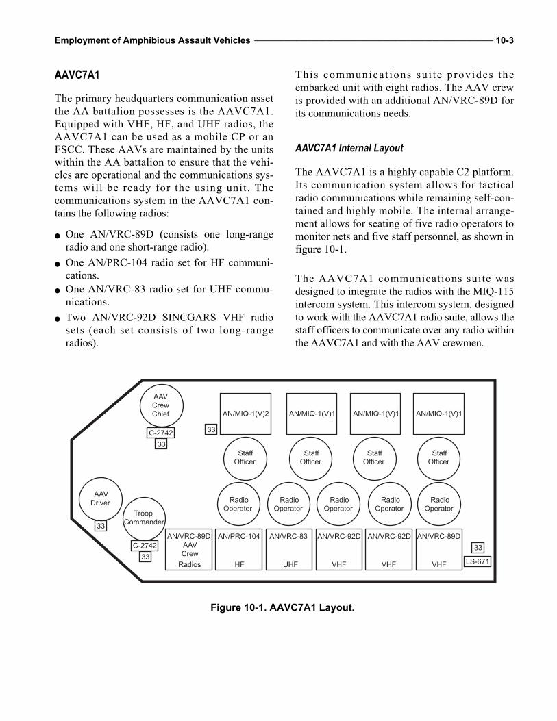
Employment of Amphibious Assault Vehicles _______________________________________________________________ 10-3
AAVC7A1
The primary headquarters communication assetthe AA battalion possesses is the AAVC7A1.Equipped with VHF, HF, and UHF radios, theAAVC7A1 can be used as a mobile CP or anFSCC. These AAVs are maintained by the unitswithin the AA battalion to ensure that the vehi-cles are operational and the communications sys-tems will be ready for the using unit. Thecommunications system in the AAVC7A1 con-tains the following radios:
One AN/VRC-89D (consists one long-rangeradio and one short-range radio).
One AN/PRC-104 radio set for HF communi-cations.
One AN/VRC-83 radio set for UHF commu-nications.
Two AN/VRC-92D SINCGARS VHF radiosets (each set consists of two long-rangeradios).
This communicat ions su i te provides theembarked unit with eight radios. The AAV crewis provided with an additional AN/VRC-89D forits communications needs.
AAVC7A1 Internal Layout
The AAVC7A1 is a highly capable C2 platform.Its communication system allows for tacticalradio communications while remaining self-con-tained and highly mobile. The internal arrange-ment allows for seating of five radio operators tomonitor nets and five staff personnel, as shown infigure 10-1.
The AAVC7A1 communications suite wasdesigned to integrate the radios with the MIQ-115intercom system. This intercom system, designedto work with the AAVC7A1 radio suite, allows thestaff officers to communicate over any radio withinthe AAVC7A1 and with the AAV crewmen.
AN/VRC-89D
AAV
Crew
AN/PRC-104
AN/MIQ-1(V)2 AN/MIQ-1(V)1 AN/MIQ-1(V)1 AN/MIQ-1(V)1
AN/VRC-83 AN/VRC-92D AN/VRC-92D AN/VRC-89D
33
33
33LS-671
C-2742
33
33C-2742
Radios HF UHF VHF VHF VHF
AAV
Driver
Troop
Commander
AAV
Crew
Chief
Staff
Officer
Staff
Officer
Staff
Officer
Staff
Officer
Radio
Operator
Radio
Operator
Radio
Operator
Radio
Operator
Radio
Operator
Figure 10-1. AAVC7A1 Layout.

10-4 _____________________________________________________________________________________________________ MCWP 3-13
NOTE: When operating in the SINCGARSradio single-channel mode, the intercomworks normally; however, difficulties withthe intercom may be experienced while oper-ating at high power in the SINCGARS radiofrequency-hopping mode.
AAVC7A1 Configured as a CombatOperations CenterWhen the AAVC7A1 is deployed as a combatoperations center (COC) for an infantry unit, thecommunications and staff personnel of the usingunit will use the radios. The AAVC7A1 willalways be accompanied by an AAVP7A1 forsupport. The AAVC7A1 and AAVP7A1 com-prise one command section. The crew of theAAVP7A1 has the ability to monitor the AA bat-talion nets with the vehicle’s AN/VRC-89Ds.
When a stop is anticipated, the AAVC7A1 andAAVP7A1 can be configured to create a COC.For example, an AAVC7A1 and AAVP7A1 canbe backed up to one another. The vehicles’ rampscan be lowered, and a fly tent or covering can bethrown over the area in between the vehicles.This configuration will give the staff increasedspace, provide light discipline at night, and allowfor a rapid displacement of the COC.
A battalion and higher-sized unit commandshould have two command sections for their use.
The unit using the AAVC7A1 may be required tomonitor more radio nets than the AAVC7 andAAVP7 (section) is capable of monitoring. Sev-eral options will satisfy this requirement. As anoption, one of the command sections can be usedas a tactical echelon, and the second commandsection can be used as a main echelon. With theuse of both echelon sections, less critical nets canbe monitored from the main echelon. The mainechelon can then pass only the necessary trafficto the tactical echelon.
As a second option, the using unit can use itsorganic communications assets in the mobileradio component vehicles to cover extra nets.Once the AAVC7A1 and AAVP7A1 are static,t he ne t s f rom the MRC veh ic l e s can beremoted into the COC. Adding extra radios tothe AAVC7A1 is not recommended becausethe enemy can use the increased electromag-netic signature to detect the COC, and the extrasignals can interfere with the radio signalsalready transmitting.
There is no standard utilization of radios or moni-tored nets in the AAVC7A1. The using unit willdetermine nets to monitor, personnel to man thenets, and staff in the AAVC7A1. The AAVC7vehicle commander should conduct indepth coor-dination with the using unit to ensure successfuldeployment on the battlefield.

CHAPTER 11. SAFETY GUIDELINES
Effective safety requires trained and skilled AAcrews, properly oriented passengers, and well-maintained vehicles. Many mishaps can bedirectly attributed to not following proper proce-dures and safety guidelines.
General Safety
The combination of heavy equipment, highmobility, limited observation, and waterbornemaneuvers creates conditions that require strictadherence to instructions and SOPs concerningAA operations. Carelessness, recklessness, short-cuts, and inattention can result in serious injuriesto personnel and damage to equipment. Person-nel must be instructed, inspected, reminded, andcorrected on a continuous basis about followingproper procedures.
Responsibilities
Safety is the responsibility of all Marines. How-ever, the troop leaders embarked on AAVs andAA unit leaders share specific responsibilities toensure safe operations.
Embarked Troop Leaders While aboard AAVs, the senior troop leaderpresent is responsible for briefing embarked per-sonnel on their responsibilities as passengersaboard AAVs. The senior AA representativepresent has the final decision if the safety of theAAV, crew or passengers is in question.
AA Unit LeadersWhen AAVs are employed, the safety ofembarked personnel and proper operation ofvehicles falls on the senior AA representativepresent. This AA unit leader establishes effectiveC2 procedures and ensures the safety of person-nel on and around the vehicles. The AA unit
leader should be the primary advisor to sup-ported infantry units on safety aspects of AAoperations and mechanical operability of AAVs.
Crewmen The crew chief is responsible for the performanceof the AAV and the safety of its passengers andcrew. The third crewman advises the crew chief ofthe situation and physical welfare of embarkedtroops. In an emergency, the third crewman isresponsible for quelling panic and assisting troopsin an orderly evacuation of the vehicle.
Vehicle Employment
The safety of crew and passengers embarked inamphibious vehicles is protected through strictadherence to the following guidelines:
Smoking is not allowed on or in AAVs. Embarked troops must wear helmets and notride topside.
Troops on foot should give an AAV a wideberth, because the field of vision from aclosed-up AAV is limited.
Open personnel hatches must be secured withrestraints when the AAV is moving, becauseunsecured open hatches can inadvertently closeon a person’s hands and head. Personnel ridingin the AAV open-hatch area will not ride in thevehicle with chests extending above the hatchopening.
Hatches must be closed and locked while theAAV is transiting through the surf zone.
Front and rear ground guides must be usedwhen vehicles are backing up or moving incongested areas, while troops are on the deckor during periods of reduced visibility.
Personnel must stand clear of the ramp areawhen the ramp is being raised or lowered. Inother than tactical situations, the vehicle’s hornmust be sounded three times before the ramp israised or lowered. An inoperable ramp will be

11-2 _____________________________________________________________________________________________________ MCWP 3-13
held with a ramp jack, a sign indicating “rampheld by jack” will be placed on the back andinside of the vehicle, and a tow cable will beattached from the mooring cleats to the towshackle.
Plenums will be raised and lowered by a mini-mum of two personnel; if the plenum springsare bad, at least three personnel will raise andlower them. Personnel must ensure their fin-gers and toes are clear and that no personnelare inside the engine compartment before low-ering the plenums.
AAVs must never operate alone on land or inthe water; a minimum of two vehicles willoperate together.
AAV must not be left with the engine runningwithout an operator in the driver’s seat.
Preventive Maintenance
AAVs require time for preventive and correctivemaintenance. Preoperational, prewater, and post-operational checks and services are required athalt. Generally, a minimum of 1 hour of PMshould be planned for every 7 hours of operationin the field. While performing PM, crewmenshould be careful when dealing with hazardousmaterial, handling engine and drivetrain covers,and moving on top of the vehicle.
Hazardous MaterialsPersonnel must take extra precautions or wear thecorrect personal protective equipment when deal-ing with hazardous materials (e.g., POL, hot radi-ator fluid, battery acid). Opening radiator capswhen the fluid is hot can cause the fluid to spray,resulting in severe burns to personnel. Spilling orsplashing battery acid can cause severe burns toskin and eyes.
Engine and Drivetrain CoversCovers must be properly installed before AAVsare operated. Unsuspecting crew and passengersaround uncovered lateral drive shafts or engineswith missing panels can be severely injured.
Moving on Top of Vehicle
While working and moving around on top ofvehicles, personnel must remain situationallyaware, because many Marines have slipped orfallen off vehicles.
Operational Briefs
Before an operation, the senior AA unit leader willensure AAV leaders, vehicle crew chiefs, andcrewmen receive an operational briefing to includeconcept of operations, anticipated water/terrainconditions, a review of emergency and immediateaction procedures, and safety precautions.
Passenger Orientation
At the beginning of each operation, the AAVvehicle commander will ensure that safety orien-tation classes are conducted for embarking units.The orientation should include vehicle employ-ment and capabilities, emergency procedures, andspecific training considerations.
Waterborne Safety
Safety in AAV water operations is paramount.Often embarked troops will have only limitedexperience in waterborne operations. AAVMarines conducting these operations must havea clear understanding of required equipment,operational requirements, safety criteria, wateroperating speeds and distances, emergency sig-nals, and embarked troops’ safety procedures. Inaddition, embarked troops must have a clearunderstanding of what their safety roles andresponsibilities are when on AAVs in the water.
Required Equipment
Each AAV has personal and vehicle equipmentthat ensure safe operations while conductingwater operations.

Employment of Amphibious Assault Vehicles _______________________________________________________________ 11-3
Personal The AAV passengers and crew must be properlyoutfitted with their lifejackets, helmets, flak jack-ets, and weapons before the AA vehicle com-mander orders launch into the water.
Lifejackets. Lifejackets must receive an opera-tional check before being worn, to include a ser-viceable carbon dioxide cartridge, light orchemical light, and whistle. Before launching, theAAV vehicle commander ensures embarked per-sonnel wear lifejackets and secure them aroundthe waist. Embarked personnel and crew willblow three puffs of air into their lifejacket beforelaunching. AAV crewmen required to come top-side while waterborne for line handling, transferoperations or rescue procedures will blow anadditional two puffs of air into their lifejackets.
Helmet. While embarked in operating AAVs,personnel must wear their helmets (i.e., CVC orKevlar).
Flak Jackets and 782 Gear. Embarked troops willwear the lifejacket under their flak jackets and 782gear that will be worn loose enough to jettisonwithout delay if required. Upon touching down,lifejackets can be removed and equipment fastened.
Weapons. During training and combat opera-tions, troops will invert and put their weapons incondition 3 (i.e., magazine inserted, weapon onsafe, and bolt forward on an empty chamber).When exiting the vehicle, troops will change theirweapons to a condition 1.
Vehicle Vehicles must have the following equipment onboard before launching:
One November flag. Two red and two white flares for night wateroperation.
Two 50-foot towropes with spliced eyelets. Two serviceable boat hooks. First aid kit.
Two chemical lights mounted on starboardcargo hatch handles.
Ax mounted on the turret. Battle lantern or searchlight.
Operational Requirements
The following reports, checklists, and trainingmust be completed before launching vehicles:
Prewater operational checklists must be com-pleted before vehicles enter water deep enoughto float the vehicle.
SUROBs must be completed before launchingAAVs in the ocean to determine if surf condi-tions meet the minimum safety criteria.
Waterborne vehicle orientation must be briefedto embarked personnel before the vehicleenters the water. The brief will include theproper use of the lifejacket, wearing of equip-ment, and weapons considerations. In addi-tion, emergency procedures (e.g., transfer oftroops, vehicle abandonment, man overboard,actions for sinking vehicles) will be explainedand practiced.
Personnel manifest of passengers and crew-men must be prepared before the AAV islaunched. The manifest will include eachembarked person’s name, rank, and SocialSecurity number. Passengers listed on themanifest must remain on board until the crewchief authorizes debarkation.
Launch team inspections must be conductedbefore the AAV is launched. Supervised by adesignated AA unit leader, the launch teamensures bilge pumps are operational and theAAV is watertight. In addition, the teaminspects the vehicle’s ramp and ensures thepersonnel hatch remains secured until the AAVreaches land.
Swim qualifications for crewmen participatingin AA water operations must be at least at thecombat water survival 2 level.
Surf survival training and qualification shouldbe conducted on an annual basis.

11-4 _____________________________________________________________________________________________________ MCWP 3-13
Rescue TeamsThe rescue teams (RTs) will be designated beforesplash; the RT vehicle number and location willbe made known to all hands. This vehicle is theprimary rescue vehicle if an AAV becomes dis-abled, although every vehicle is a potential rescuevehicle. The RT vehicle must be capable ofreceiving personnel from a disabled AAV, andwill have a corpsman embarked.
Safety CriteriaAA unit leaders must have a good workingknowledge of the AA safety criteria. The criteriareflect different standards for general training andcombat conditions. Acceptable surf for generaltraining is a combination of the factors of vehicleload, surf height, wave types, and breaker inter-val. The three load conditions are CL 10,000 lbs,TL 5,600 lbs, and CE no load. Refer to chapter 3,table 3-2 for maximum safe surf conditions.
Water Operating Speeds and DistancesAAV operations in the water can be especiallychallenging when many vehicles are operating atthe same time in close proximity and/or in peri-ods of limited visibility. Safe distances andspeeds between AAVs must be observed. In addi-tion, AAV crewmen must know the signals forAAVs in distress should their vehicle begin sink-ing or require assistance.
Speed AfloatMaximum AAV speed afloat is 8.2 knots perhour at 2,800 RPM in calm conditions. Factorssuch as sea state, wind, current, and vehicle loadgreatly affect water speed. During daylight withunrestricted visibility, 50 meters or five AAVlengths should be kept between vehicles. Duringrestricted visibility and at night, 50 meters or lessshould be kept between vehicles, depending onthe limit of visibility.
Emergency SignalsThe VHF radio is the primary method of emer-gency communications, but secondary methodsof communications are also used for disabled andsinking vehicles.
Disabled Vehicles
During daylight, the November flag should bedisplayed from a vertical boat hook. At night, asearchlight or battle lantern should be turned onand pointed vertically. If the night signal fails,one white flare should be fired into the air.
Sinking Vehicles
During daylight, the November flag should bewaved continuously or a red flare should be firedinto the air. At night, a searchlight or battle lan-tern should be turned on and pointed vertically ora red flare should be fired into the air.
Embarked Troops
The time AAVs with embarked troops are water-borne should be limited because of the combinedeffect of heat, noise, fumes, seasickness, andclaustrophobia. Ventilation in the troop compart-ment may prevent troop discomfort and sickness.
Land Safety
Once on land, collisions with other AAVs orvehicles often result in serious injuries or deaths.In addition, AAVs are not air-conditioned andcan cause heat injury to crews or embarkedtroops if the right precautions are not followed.Safe operations of AAVs on land depend largelyon the environment in which they are operatingand crews’ ability to adjust.

Employment of Amphibious Assault Vehicles _______________________________________________________________ 11-5
Crew CompositionA minimum of two qualified crewmen will be onboard for land operations.
Operating Speeds The AAV’s safe operating speed over land isinfluenced by the following conditions:
During daylight with unrestricted visibility in acongested area, near troops, equipment orAAV parks, the AAV should not exceed5 miles per hour with ground guides.
During daylight with unrestricted visibility inan uncongested area, the AAV should notexceed 35 miles per hour.
When visibility is restricted by dust, fog,wooded areas, buildings or other AAVs, theAAV should operate at a speed slow enough topermit the vehicle to stop and move safely.
Operating DistancesThe AAV’s safe operating distance between vehi-cles is influenced by the following conditions:
During daylight with unrestricted visibility, AAVsshould maintain 50 meters or five lengths betweenvehicles.
During restricted visibility and at night, AAVsshould maintain 50 meters or the limit of visi-bility, whichever is less between vehicles.
Road CrossingsWhen AAVs cross hard surface roads (high-ways) during training exercises or administrativeroad marches, road guards must be positioned onboth sides of the crossing site at a minimum of100 yards on 55-mile per hour roads and 50 yardson 35-mile per hour roads. Road guards shouldwear reflective vests, carry flashlights or flares atnight, and position themselves to safely stop traf-fic for the crossing AAVs.
Operational EnvironmentsThe AAV’s safe operations over land can beinfluenced by unfamiliar climates and terrain.
Hot WeatherBecause heat injuries are probable in closedvehicles, personnel must have proper ventilationand constant hydration in hot weather. Watercans should be filled at every opportunity, andvehicles must be frequently checked for leaksand overheating.
DesertIn addition to hot weather conditions, high dustconditions can reduce visibility significantly andaffect AAV operations in desert terrain. Vehiclespeeds and distances must be adjusted, becausereduced visibility can cause drivers to misjudgedistances between vehicles and increase thepotential for vehicle collisions.
JungleIn a jungle environment, obstacles can limit AAVmovement to existing trails and roads.
Heavily WoodedThe AAV’s visibility and maneuverability can bereduced in heavily wooded areas.
MountainousSteep inclines and declines in mountainous ter-rain can reduce speeds and maneuverability ofvehicles. AAV drivers must keep the engine’sRPM up to ensure that the hydraulic steering isnot reduced.
Cold Weather/ArcticAAVs must be properly ventilated during coldweather conditions because the use of vehicle

11-6 _____________________________________________________________________________________________________ MCWP 3-13
heaters poses a risk of carbon monoxide poison-ing to personnel inside the vehicles. Marinesworking with all-metal vehicles are at risk ofhypothermia. In addition, AAVs can slide on icysurfaces, causing great risk to other vehicles andpersonnel on the ground.
Limited VisibilityDuring night operations when night visiondevices are used, operating speeds and distancesmust be adjusted to compensate for reduced visi-bility. Rest time must be allotted for personnelusing these devices, because night vision devicescause vision to quickly fatigue.
Other Safety Considerations
AAV vehicle commanders and embarked troopleaders must be aware of safety concerns inregards to weather, NBC operations, medicalevacuation, lasers, UGWS, LMC, and onboardvehicle fires. AAVs have unique safety guide-lines in these areas that should be reviewed.
WeatherLightning, high winds, and heavy rains can posehazards to personnel.
LightningDuring periods of lightning, personnel should stayoff the vehicle top and away from antennas.
High WindsUnsecured hatches are subject to closing or slam-ming rapidly during high wind conditions.
Heavy RainsDuring and after heavy rains, the ground canbecome unstable and cause vehicles to slide, rollor get stuck.
Nuclear, Biological, and Chemical OperationsDuring NBC operations, AAV crewmen andembarked troops can experience reduced visibil-ity and heat injuries.
Reduced VisibilityThe wearing of the f ield protective maskreduces the crew and driver’s visibility andmakes communications more difficult. This mayrequire operating the AAV at slower speeds.
Heat InjuriesThe MOPP suit with the field protective maskincreases the risk of heat injuries. If the AAVmust operate with hatches closed, leaders mustwatch personnel closely for signs of heat exhaus-tion or heat stroke. Temperatures can becomeextremely hot inside the AAV for personnel inMOPP suits.
Medical EvacuationPersonnel should know the procedures forrequesting emergency medical evacuation andpreset the medical evacuation frequency on oneradio in each vehicle before operations. Acorpsman should always be present during anyAAV operation.
LasersWhile conducting mech operations, personnelmust be advised of the eye hazards associatedwith the use of lasers. Common sources of lasersare tanks, LAVs, and aircraft providing CAS.
Up-Gunned Weapon StationStrict adherence to operational procedures must befollowed when dealing with the UGWS. The great-est risk to personnel is from a supposedly unloadedweapon. Every weapon will be treated as if it wereloaded. Personnel must know the proper proceduresfor immediate action and clearing of the MK-19

Employment of Amphibious Assault Vehicles _______________________________________________________________ 11-7
and M2 .50-caliber machine guns. Weapons shouldbe doublechecked by a section leader after live fireexercises. Personnel should be aware of the hazardsof white phosphorus in the smoke grenades.
Linear Mine ClearingAAV crews, in addition to engineer detach-ments, must be trained and certified in LMCoperations. During line-charge operations, onlyauthorized personnel should clear ranges. Thesepersonnel should be kept to a minimum number.
If the line charge is burning from the rocket dur-ing the launch or a piece of it does not detonateand is burning, the potential for the line to deto-nate on its own is great.
Onboard Vehicle FiresAAV crewmen should know immediate actionsfor onboard fires to include location of the porta-ble fire extinguisher, fire system activationlevers, and evacuation procedures.

54.3
918.57
40
321.32
CargoHatch60x108
RampOpening66x73
Center of GravityCombat Equipped
0
CL
130.56
Turret
24
CL
16
21
130.61128.66(Less EAAKBosses)
APPENDIX A. AAVP7A1 DATA
Figure A-1. AAVP7A1.
(All measurements are in inches.)

A-2 _____________________________________________________________________________________________________ MCWP 3-13
General
Crew 3
Weight Unloaded: 46,314 pounds (with enhanced appliqué armor kit [EAAK], less crew, fuel, on-equipment material [OEM], and ammunition)
Combat-equipped: 50,758 pounds (EAAK, crew, fuel, OEM, and ammunition)
Troop-loaded: 56,743 pounds (combat-equipped with troops)
Cargo-loaded: 60,758 pounds (combat-equipped with cargo)
Mine clearance kit: 61,158 pounds (combat-equipped with MK1 model 0 mine clearance system
Load capacity 21 combat-equipped troops (at 285 pounds each) or 10,000 pounds of cargo
Center of gravity Unloaded: 52.8 inches above ground, 84.4 inches from station 100.0
Combat-equipped: 54.3 inches above ground, 91.0 inches from station 100.0
Troop-loaded: 53.6 inches above ground, 97.0 inches from station 100.0
Cargo-loaded: 52.8 inches above ground, 100.3 inches from station 100.0
Mine clearance kit: 54.4 inches above ground, 103.2 inches from station 100.0
Mean seawater draft (cargo-loaded) 75.2 inches
Freeboard at bow (station 34) 18.9 inches
Freeboard at stern (station 346) 10.8 inches
Unit ground pressure (cargo-loaded, zero penetration) 9.1 pounds per square inch
Fuel capacity 171 gallons
Performance
Gross horsepower to weight ratio (cargo-loaded) 13.2 horsepower per ton
Net horsepower to weight ratio (cargo-loaded) 8.8 horsepower per ton
Drawbar pull (maximum at stall tractive effort) 42,644 pounds on level, firm terrain
Cruising range Land at 25 miles per hour: 300 miles
Water at 2,600 rotations per minute: 7 hours
Cruising speed Land: 20 to 30 miles per hour
Water: 6 miles per hour
Maximum speed forward Land: 45 miles per hour
Water: 8.2 miles per hour
Maximum speed reverse Land: 12 miles per hour
Water: 4.5 miles per hour
Obstacle ability 8-foot trench span, 3-foot vertical wall
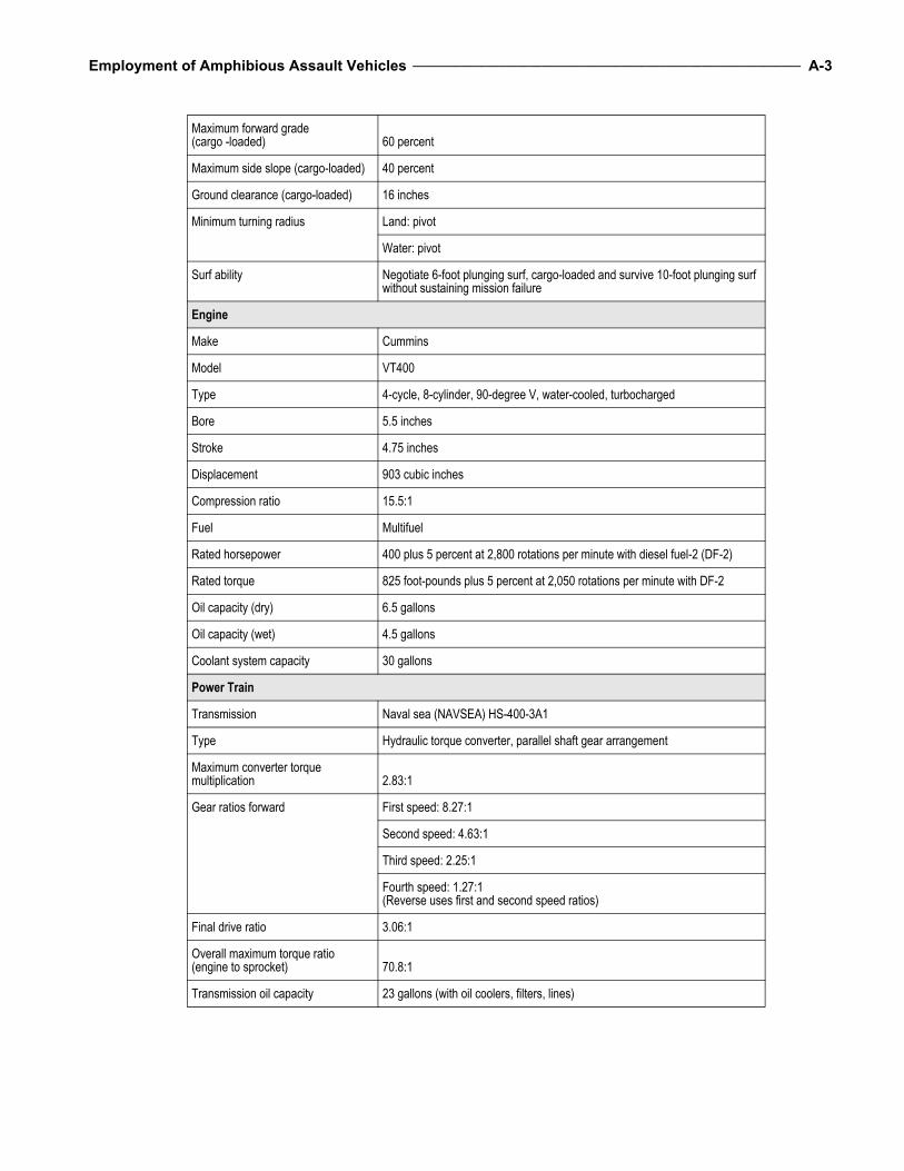
Employment of Amphibious Assault Vehicles _______________________________________________________________ A-3
Maximum forward grade(cargo -loaded) 60 percent
Maximum side slope (cargo-loaded) 40 percent
Ground clearance (cargo-loaded) 16 inches
Minimum turning radius Land: pivot
Water: pivot
Surf ability Negotiate 6-foot plunging surf, cargo-loaded and survive 10-foot plunging surf without sustaining mission failure
Engine
Make Cummins
Model VT400
Type 4-cycle, 8-cylinder, 90-degree V, water-cooled, turbocharged
Bore 5.5 inches
Stroke 4.75 inches
Displacement 903 cubic inches
Compression ratio 15.5:1
Fuel Multifuel
Rated horsepower 400 plus 5 percent at 2,800 rotations per minute with diesel fuel-2 (DF-2)
Rated torque 825 foot-pounds plus 5 percent at 2,050 rotations per minute with DF-2
Oil capacity (dry) 6.5 gallons
Oil capacity (wet) 4.5 gallons
Coolant system capacity 30 gallons
Power Train
Transmission Naval sea (NAVSEA) HS-400-3A1
Type Hydraulic torque converter, parallel shaft gear arrangement
Maximum converter torque multiplication 2.83:1
Gear ratios forward First speed: 8.27:1
Second speed: 4.63:1
Third speed: 2.25:1
Fourth speed: 1.27:1(Reverse uses first and second speed ratios)
Final drive ratio 3.06:1
Overall maximum torque ratio (engine to sprocket) 70.8:1
Transmission oil capacity 23 gallons (with oil coolers, filters, lines)

A-4 _____________________________________________________________________________________________________ MCWP 3-13
Running Gear
Type Torsion bar and tube suspension, front sprocket, raised rear idler
Wheels 6 rubber-tired, dual per side, 26-inch diameter
Return idlers 1 per side, 20-inch diameter wheels
Sprocket Teeth: 11
Feet per revolution: 5.5
Shock absorbers 3 per side
Track Steel, single pin, rubber bushed, with replaceable pads
Blocks 85 maximum per side
Pitch: 6 inches
Weight per block: 34 pounds maximum
Weight per side: 2,890 pounds maximum
Water Propulsion
Water jet pumps Capacity: 14,000 gallons per minute
Thrust: 3,025 pounds static
Quantity: 2
Location: port, starboard, and aft
Steering and reverse Jet deflectors
Electrical
Nominal voltage 24 volts, direct current
Generator 300 ampere
Battery Volts: 12
Type: 6-cell, terminal, lead
Quantity: 4
Communication
Control monitor C-11291 2
Radio frequency amplifier AM-7238 2
Vehicular amplifier adapter AM-7239 2
Mount MT-6353 2
Loudspeaker LS-671 1
Receiver-transmitter RT-1523 4
Antennas AS-3916 4
Audio frequency amplifier AM-7162 1
Intercom control box C-11133 4
Intercom control box C-11135 1

Employment of Amphibious Assault Vehicles _______________________________________________________________ A-5
Armor
Permanent hull Aluminum armor plate
Ramp outer 1.000 inch
Ramp inner .500 inch
Sides 1.750, 1.395 and 1.222 inches
Top 1.185 inches
Bottom 1.185 inches
Stern 1.395 inches
EAAK Protection for vehicle side and slope, troop compartment overhead, and slope rack kit for sponson stowage of OEM
Attachment: boss and joint offset method
Material: homogeneous harden steel, rubber, mild steel composite
Boss offset from hull (no armor): 0.75 inch per side
Maximum offset from hull: 8.50 inches per side
Fire Extinguishers
Automatic fire sensing and suppression system:
Cylinders 3
Locations Aft engine compartment bulkhead, and forward starboard stanchion
Capacity 7 pounds each, Halon 1301
Sensors 4
Portable Cylinders: 1
Location: starboard, aft
Capacity: 5 pounds carbon dioxide
Manual fire suppression system:
Troop compartment Cylinders: 1
Location: port sponson
Capacity: 17 pounds Halon 1301
Engine Compartment Cylinders: 2
Location: one in driver's compartment and one in aft engine compartment
Bulkhead capacity 7 pounds each, Halon 1301
Vision and Sighting Equipment
Driver's station:
Direct vision blocks 7
Driver's night vision device AN/VVS-2(V)1A: 1
AN/VAS-5A(V)6: 1 (Note: Device AN/VAS-5A(V)6 is currently being fielded.)
Commander's station:
Direct vision blocks 7

A-6 _____________________________________________________________________________________________________ MCWP 3-13
Periscope, M27 1
Device AN/VAS-5A(V)6 1 (Note: Device is slaved to drivers night vision device.)
Weapon station:
Direct vision blocks 7
Gunner's sight M36E2 (projected reticle)
Daylight 1X or 7X power
Night 7.1X power (passive vision assembly)
Ramp, direct vision blocks 1
Cargo Compartment
Length 13.5 feet
Width 6.0 feet
Height 5.5 feet
Volume 445.5 cubic feet
Capacity 21 combat-equipped troops
Armament and Ammunition
Upgunned weapons station, improved:
Weight 2,365 pounds
Starboard overhang 1.14 Inches
Traverse 360 degrees
Elevation Plus 45 degrees
Depression - 8 degrees
Power control system Electric-manual
Weapons:
M2 heavy-barrel caliber. 50 machine gun
Rate of fire (cyclic): 450 to 550 rounds per minute
Muzzle velocity: 3,050 feet per second
Maximum effective range: 2,000 yards (1,830 meters)
MK-19 model 3 40-millimetermachine gun
Rate of fire (cyclic): 325 to 375 rounds per minute
Muzzle velocity: 790 feet per second
Maximum effective range: 1,640 yards (1,500 meters)
Ammunition Caliber .50: 200 ready rounds, 1,000 rounds stowed in 10 ammunition boxes
40 millimeters: 96 ready rounds, 768 rounds stowed in 16 ammunition boxes
M257 smoke grenade launchers Quantity: 2 assembly
Total: 8 UKL8A1 or UKL8A3 grenades
M16 A2, 5.56-millimeter rifle Quantify: 3 (troop issue)
Infantry weapons mount kit 2 MK 16 gun stands on vehicle rear deck

Employment of Amphibious Assault Vehicles _______________________________________________________________ A-7
Navigation Equipment
(Note: None integrated/organic to the AAV7A1.)
Bilge Pumps
Electric (minimum each pump) 100 gallons per minute
Hydraulic (minimum each pump) 115 gallons per minute
Other
Capability enhancements Bow plane assembly NAVSEA part number (P/N) 6227757
Chemical agent resistant coatings
Special mission kits Visor kit, NAVSEA P/N 2587015
Litter kit, NAVSEA P/N 5428676
Winterization kit, NAVSEA P/N 2600063
MK 1 model 0 mine clearance system, weight: 10,400 pounds (fully loaded)
Production FMC Corporation
Date first prototype: 1979
Date first production vehicle: 1983

APPENDIX B. AAVP7A1 (RAM/RS) DATA
43.5
968.57
321.32
CargoHatch60x108
RampOpening66x73
Center of GravityCombat Equipped
130.56
Turret
24
CL
16
21
130.61128.66(Less EAAKBosses)
400
(All measurements are in inches.)
Figure B-1. AAVP7A1 (RAM/RS).
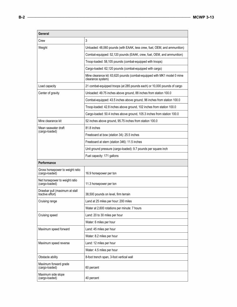
B-2 _____________________________________________________________________________________________________ MCWP 3-13
General
Crew 3
Weight Unloaded: 48,060 pounds (with EAAK, less crew, fuel, OEM, and ammunition)
Combat-equipped: 52,120 pounds (EAAK, crew, fuel, OEM, and ammunition)
Troop-loaded: 58,105 pounds (combat-equipped with troops)
Cargo-loaded: 62,120 pounds (combat-equipped with cargo)
Mine clearance kit: 63,620 pounds (combat-equipped with MK1 model 0 mine clearance system)
Load capacity 21 combat-equipped troops (at 285 pounds each) or 10,000 pounds of cargo
Center of gravity Unloaded: 49.75 inches above ground, 88 inches from station 100.0
Combat-equipped: 43.5 inches above ground, 96 inches from station 100.0
Troop-loaded: 42.8 inches above ground, 102 inches from station 100.0
Cargo-loaded: 50.4 inches above ground, 105.3 inches from station 100.0
Mine clearance kit 52 inches above ground, 95.75 inches from station 100.0
Mean seawater draft(cargo-loaded)
81.8 inches
Freeboard at bow (station 34): 25.5 inches
Freeboard at stern (station 346): 11.5 inches
Unit ground pressure (cargo-loaded): 9.7 pounds per square inch
Fuel capacity: 171 gallons
Performance
Gross horsepower to weight ratio (cargo-loaded) 16.9 horsepower per ton
Net horsepower to weight ratio (cargo-loaded) 11.3 horsepower per ton
Drawbar pull (maximum at stall tractive effort) 38,500 pounds on level, firm terrain
Cruising range Land at 25 miles per hour: 200 miles
Water at 2,600 rotations per minute: 7 hours
Cruising speed Land: 20 to 30 miles per hour
Water: 6 miles per hour
Maximum speed forward Land: 45 miles per hour
Water: 8.2 miles per hour
Maximum speed reverse Land: 12 miles per hour
Water: 4.5 miles per hour
Obstacle ability 8-foot trench span, 3-foot vertical wall
Maximum forward grade(cargo-loaded) 60 percent
Maximum side slope(cargo-loaded) 40 percent
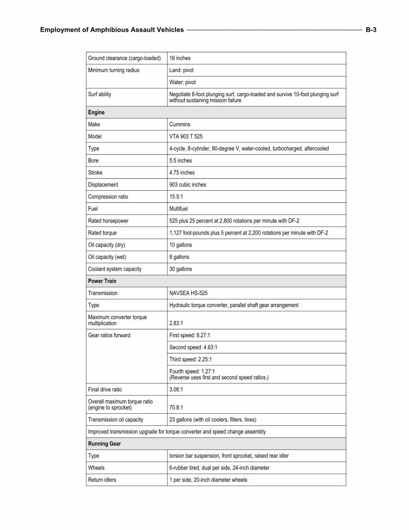
Employment of Amphibious Assault Vehicles _______________________________________________________________ B-3
Ground clearance (cargo-loaded) 16 inches
Minimum turning radius Land: pivot
Water: pivot
Surf ability Negotiate 6-foot plunging surf, cargo-loaded and survive 10-foot plunging surf without sustaining mission failure
Engine
Make Cummins
Model VTA 903 T 525
Type 4-cycle, 8-cylinder, 90-degree V, water-cooled, turbocharged, aftercooled
Bore 5.5 inches
Stroke 4.75 inches
Displacement 903 cubic inches
Compression ratio 15.5:1
Fuel Multifuel
Rated horsepower 525 plus 25 percent at 2,800 rotations per minute with DF-2
Rated torque 1,127 foot-pounds plus 5 percent at 2,200 rotations per minute with DF-2
Oil capacity (dry) 10 gallons
Oil capacity (wet) 8 gallons
Coolant system capacity 30 gallons
Power Train
Transmission NAVSEA HS-525
Type Hydraulic torque converter, parallel shaft gear arrangement
Maximum converter torque multiplication 2.83:1
Gear ratios forward First speed: 8.27:1
Second speed: 4.63:1
Third speed: 2.25:1
Fourth speed: 1.27:1(Reverse uses first and second speed ratios.)
Final drive ratio 3.06:1
Overall maximum torque ratio (engine to sprocket) 70.8:1
Transmission oil capacity 23 gallons (with oil coolers, filters, lines)
Improved transmission upgrade for torque converter and speed change assembly
Running Gear
Type torsion bar suspension, front sprocket, raised rear idler
Wheels 6-rubber tired, dual per side, 24-inch diameter
Return idlers 1 per side, 20-inch diameter wheels

B-4 _____________________________________________________________________________________________________ MCWP 3-13
Support rollers 2 single and 1 double per side, 20-inch diameter rollers
Sprocket Teeth: 11
Feet per revolution: 5.5
Shock absorbers 4 per side
Track Steel, single-pin, rubber-bushed, with replaceable pads
Blocks 85 maximum per side
Pitch: 6 inches
Weight per block: 35.4 pounds maximum
Weight per side: 3,009 pounds maximum
Water Propulsion
Water Jet Pumps Capacity: 14,000 gallons per minute
Thrust: 3,025 pounds static
Quantity: 2
Location: port and starboard, aft
Steering and reverse Jet deflectors
Electrical
Nominal voltage 24 volts, direct current
Generator 300 ampere, 28 volts, direct current
Battery Volts: 12
Quantity: 4
Communication
Vehicle system AN/VIC-2 (V)
Radio AN/VRC-89A radio set: 2
Communications security equipment (integrated into the RT-1523)
AN/VIC-2(V) intercom system 5 stations
Control monitor C-11291 2
Radio frequency amplifierAM-7238 2
Vehicular amplifier adapterAM-7239 2
Mount MT-6353 2
Loudspeaker LS-671 1
Receiver-transmitter RT-1523 4
Antennas AS-3916 4
Audio frequency amplifier AM-7162 1
Intercom control box C-11133 4
Intercom control box C-11135 1
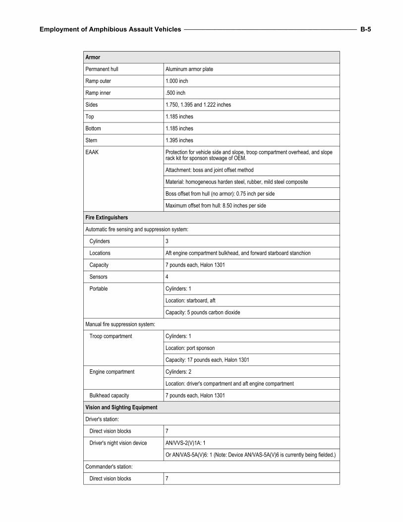
Employment of Amphibious Assault Vehicles _______________________________________________________________ B-5
Armor
Permanent hull Aluminum armor plate
Ramp outer 1.000 inch
Ramp inner .500 inch
Sides 1.750, 1.395 and 1.222 inches
Top 1.185 inches
Bottom 1.185 inches
Stern 1.395 inches
EAAK Protection for vehicle side and slope, troop compartment overhead, and slope rack kit for sponson stowage of OEM.
Attachment: boss and joint offset method
Material: homogeneous harden steel, rubber, mild steel composite
Boss offset from hull (no armor): 0.75 inch per side
Maximum offset from hull: 8.50 inches per side
Fire Extinguishers
Automatic fire sensing and suppression system:
Cylinders 3
Locations Aft engine compartment bulkhead, and forward starboard stanchion
Capacity 7 pounds each, Halon 1301
Sensors 4
Portable Cylinders: 1
Location: starboard, aft
Capacity: 5 pounds carbon dioxide
Manual fire suppression system:
Troop compartment Cylinders: 1
Location: port sponson
Capacity: 17 pounds each, Halon 1301
Engine compartment Cylinders: 2
Location: driver's compartment and aft engine compartment
Bulkhead capacity 7 pounds each, Halon 1301
Vision and Sighting Equipment
Driver's station:
Direct vision blocks 7
Driver's night vision device AN/VVS-2(V)1A: 1
Or AN/VAS-5A(V)6: 1 (Note: Device AN/VAS-5A(V)6 is currently being fielded.)
Commander's station:
Direct vision blocks 7

B-6 _____________________________________________________________________________________________________ MCWP 3-13
Periscope, M27 1
Device AN/VAS-5A(V)6 1 (Note: Device is slaved to the driver’s night vision.)
Weapon Station:
Direct vision blocks 7
Gunner's sight M36E2 (projected reticle)
Daylight 1X or 7X power
Night 7.1X power (passive vision assembly)
Ramp, direct vision blocks 1
Cargo Compartment
Length 13.5 feet
Width 6.0 feet
Height 5.5 feet
Volume 445.5 cubic feet
Capacity 21 combat-equipped troops
Armament and Ammunition
Upgunned weapons station, improved:
Weight 2,365 pounds
Starboard overhang 1.14 inches
Traverse 360 degrees
Elevation Plus 45 degrees
Depression 8 degrees
Power control system Electric-manual
Weapons:
M2 heavy-barrel, caliber .50 machine gun Rate of fire (cyclic): 450-550 rounds per minute
Muzzle velocity: 3,050 feet per second
Maximum effective range: 2,000 yards (1,830 meters)
MK-19 model 3 40-millimeter machine gun Rate of fire (cyclic): 325-375 rounds per minute
Muzzle velocity: 790 feet per second
Maximum effective range: 1,640 yards (1,500 meters)
Ammunition Caliber .50: 200 ready rounds, 1,000 rounds stowed in 10 ammunition boxes
40 millimeters: 96 ready rounds, 768 rounds stowed in 16 ammunition boxes

Employment of Amphibious Assault Vehicles _______________________________________________________________ B-7
M257 Smoke grenade launchers Quantity: 2 assembly
Total: 8 UKL8A1 or UKL8A3 grenades
M16 A2, 5.56-millimeter rifle Quantity: 3 (troop issue)
Infantry weapons mount kit 2 MK 16 gun stands on vehicle rear deck
Navigation Equipment
Precision lightweight globalpositioning system receiver P/N 822-0077-002
Tactical navigation digital compass system light 1
Position location reporting system AN/VSQ-1
Bilge Pumps
Electric (minimum each pump) 100 gallons per minute
Hydraulic (minimum each pump) 115 gallons per minute
Other
Capability enhancements Bow plane assembly, NAVSEA P/N 6227757
Chemical agent resistant coatings
Special mission kits Visor kit, NAVSEA P/N 2587015
Litter kit, NAVSEA P/N 5428676
Winterization kit, NAVSEA P/N 2600063
MK 1 model 0 mine clearance system, weight: 10,400 pounds (fully loaded)
Production United Defense Limited Partnership Corporation
Date first prototype: 1995
Date first production vehicle: 1998

14.20
96.3
40
40
321.32
CargoHatch60x108
RampOpening66x73
Center of GravityCombat Equipped
16
21
131.72
0
APPENDIX C. AAVC7A1 DATA
Figure C-1. AAVC7A1.
(All measurements are in inches.)

C-2 _____________________________________________________________________________________________________ MCWP 3-13
General
Crew 3
Weight Unloaded: 49,614 pounds (with EAAK, less crew, fuel, OEM, and ammunition)
Combat-equipped: 53,019 pounds (with EAAK, crew, fuel, OEM, and ammunition)
Center of gravity Unloaded: 49.4 inches above ground, 94.4 inches from station 100.0
Combat-equipped: 51.3 inches above ground, 95.5 inches from station 100.0
Mean seawater draft (combat-equipped) Approximately 69.0 inches
Freeboard at bow (station 34) Approximately 20.2 inches
Freeboard at stern (station 346) Approximately 21.9 inches
Unit ground pressure (combat-equipped, zero penetration) 7.9 pounds per square inch
Fuel capacity 171 gallons
Performance
Gross horsepower to weight ratio (combat-equipped) 15.2 horsepower per ton
Net horsepower to weight ratio (combat-equipped) 10.1 horsepower per ton
Drawbar pull (maximum at stall tractive effort) 38,934 pounds on level, firm terrain
Cruising range Land at 25 miles per hour: 300 miles
Water at 2,600 rotations per minute: 7 hours
Cruising speed Land: 20 to 30 miles per hour
Water: 6 miles per hour
Maximum speed forward Land: 45 miles per hour
Water: 8.2 miles per hour
Maximum speed reverse Land: 12 miles per hour
Water: 4.5 miles per hour
Obstacle ability 8-foot trench span, 3-foot vertical wall
Maximum forward grade(combat-equipped) 60 percent
Maximum side slope (combat-equipped) 40 percent
Ground clearance (combat-equipped) 16 inches
Minimum turning radius Land: pivot
Water: pivot
Surf ability Negotiate 6-foot plunging surf, combat-equipped and survive 10-foot plunging surf without sustaining mission failure

Employment of Amphibious Assault Vehicles _______________________________________________________________ C-3
Engine
Make Cummins
Model VT400
Type 4-cycle, 8-cylinder, 90-degree V, water-cooled, turbocharged
Bore 5.5 inches
Stroke 4.75 inches
Displacement 903 cubic inches
Compression ratio 15.5:1
Fuel Multifuel
Rated horsepower 400 plus 5 percent at 2,800 rotations per minute with DF-2
Rated torque 825 foot-pounds 5 percent at 2,050 rotations per minute with DF-2
Oil capacity (dry) 6.5 gallons
Oil capacity (wet) 4.5 gallons
Coolant system capacity 30 gallons
Power Train
Transmission NAVSEA HS-400-3A1
Type Hydraulic torque converter, parallel shaft gear arrangement
Maximum converter torque multiplication 2.83:1
Gear ratios forward First speed: 8.27:1
Second speed: 4.63:1
Third speed: 2.25:1
Fourth speed: 1.27:1(Reverse uses first and second speed ratios)
Final drive ratio 3.06:1
Overall maximum torque ratio (engine to sprocket) 70.8:1
Transmission oil capacity 23 gallons (with oil coolers, filters, lines)
Improved transmission upgrade for torque converter, steer and brake assembly gears, and oil filter
Running Gear
Type Torsion bar and tube suspension, front sprocket, raised rear idler
Wheels 6 rubber-tired, dual per side, 26-inch diameter
Return idlers 1 per side, 20-inch diameter wheels
Sprocket Teeth: 11
Feet per revolution: 5.5
Shock absorbers 3 per side
Track Steel, single-pin, rubber-bushed, with replaceable pads

C-4 _____________________________________________________________________________________________________ MCWP 3-13
Blocks 85 maximum per side
Pitch 6 inches
Weight per block 34 pounds maximum
Weight per side 2,890 pounds maximum
Water Propulsion
Water jet pumps Capacity: 14,000 gallons per minute
Thrust: 3,025 pounds static
Quantity: 2
Location: port and starboard, aft
Steering and reverse: jet deflectors
Electrical
Nominal voltage 24 volts, direct current
Generator 300 ampere, 28 volts, direct current
Battery Volts: 12
Type: 6 cell, terminal, lead
Quantity: 4
Communication Vehicle System
Control monitor C-11291 2
Radio frequency amplifierAM-7238 4
Amplifier adapter AM-7239 6
Mount MT-6352 4
Mount MT-6353 2
Loudspeaker LS-671 1
Receiver-transmitter RT-1523 8
Antenna AS-3900 8
Audio amplifier AM-7162 1
Intercom control box C-11133 4
Intercom control box C-11135 1
Communication control boxMIQ-1(V)-3 5
Communication control boxMIQ-1(V)-2 2
Communication control boxMIQ-1(V)-1 3
Communication system controller C-10879/MSQ-115 1
Current regulator CN-1549 5

Employment of Amphibious Assault Vehicles _______________________________________________________________ C-5
Receiver-transmitter RT-1319/VRC-83 1
Receiver-transmitter RT-1209/PRC-104 1
Armor
Permanent hull Aluminum armor plate
Ramp outer 1.000 inch
Ramp inner .500 inch
Sides 1.750, 1.395, and 1.222 inches
Top 1.185 inches
Bottom 1.185 inches
Stern 1.395 inches
EAAK Protection for vehicle side and slope, troop compartment overhead: and slope rack kit for sponson stowage of OEM
Attachment Boss and joint offset method
Material Homogeneous harden steel, rubber, mild steel composite
Boss offset from hull (no armor) 0.75 inch per side
Maximum offset from hull 8.50 inches per side
Fire Extinguishers
Automatic fire sensing and suppression system:
Cylinders 3
Location Aft engine compartment bulkhead, and forward starboard stanchion
Capacity 7 pounds each, Halon 1301
Sensors 4
Portable:
Cylinders 1
Location Starboard, aft
Capacity 5 pounds carbon dioxide
Manual fire suppression system:
Troop compartment Cylinders: 1
Location: port sponson
Capacity: 17 pounds each, Halon 1301
Engine compartment Cylinders: 2
Location: driver's compartment and aft engine compartment bulkhead
Capacity: 7 pounds each, Halon 1301 each
Vision and Sighting Equipment
Driver's Station Direct vision blocks: 7
Driver's night vision viewer AN/VAS-5A(V)6: 1

C-6 _____________________________________________________________________________________________________ MCWP 3-13
Master Station Direct vision blocks: 7
Periscope, M27: 1
Vehicle commander's station, direct vision blocks 9
Ramp, direct vision blocks 1
Personnel Complement
Crew (vehicle commander, driver, assistant driver)
3
Radio operators 5
Unit commander and staff 5
Armament and Ammunition
M240G, machine gun, pintle-mounted 1
Ammunition 7.62 millimeters; 1,000 rounds stowed
M16 A2 5.56-millimeter rifle, quantity 3 (crew issue)
Navigation Equipment
(None is integrated/organic to the AAV7A1.)
Bilge Pumps
Electric (minimum each pump) 100 gallons per minute
Hydraulic (minimum each pump) 120 gallons per minute
Other
Capability enhancements Bow plane assembly, NAVSEA P/N 6227757
Chemical agent resistant coatings
Special mission kits Visor kit, NAVSEA P/N 2587015
Winterization kit, NAVSEA P/N 2600063
Production FMC Corporation
Date first prototype: 1979
Date first production vehicle: 1983

50.354.9
320.4
CargoHatch60x108
RampOpening66x73
Center of GravityCombat Equipped
16
21
400
APPENDIX D. AAVR7A1 DATA
Figure D-1. AAVR7A1.
(All measurements are in inches.)

D-2 _____________________________________________________________________________________________________ MCWP 3-13
General
Crew 5
Weight Unloaded: 50,113 pounds (less crew, fuel, and ammunition)
Combat-equipped: 52,123 pounds (crew, fuel, OEM, and ammunition)
Center of Gravity Unloaded: 54.0 inches above ground, 90.4 inches from station 100.0
Combat-equipped: 54.9 inches above ground, 90.8 inchesfrom station 100.0
Maximum seawater draft (combat-equipped) approximately 68.0 inches
Freeboard to driver's hatch coaming: approximately 37.3 inches
Freeboard to inlet of aspirator valve: approximately 39.0 inches
Unit ground pressure (combat-equipped, zero penetration) 7.8 pounds per square inch
Fuel capacity 171 gallons
Performance
Gross horsepower to weight ratio (combat-equipped) 15.3 horsepower per ton
Net horsepower to weight ratio (combat-equipped) 10.2 horsepower per ton
Drawbar pull (maximum at stalltractive effort) 42,036 pounds on level firm terrain
Cruising range Land at 25 miles per hour: 300 miles
Water at 2,600 rotations per minute: 7 hours
Cruising speed Land: 20 to 30 miles per hour
Water: 6 miles per hour
Maximum speed forward Land: 45 miles per hour
Water: 8.2 miles per hour
Maximum speed reverse Land: 12 miles per hour
Water: 4.5 miles per hour
Obstacle ability 8-foot trench span, 3-foot vertical wall
Maximum forward grade (combat-equipped) 60 percent
Maximum side slope (combat-equipped) 40 percent
Ground clearance (combat-equipped) 16 inches
Minimum turning radius Land: pivot
Water: pivot
Surf ability Negotiate 6-foot plunging surf, combat-equipped and survive 10-foot plunging surf without sustaining mission failure
Engine
Make Cummins
Model VT400
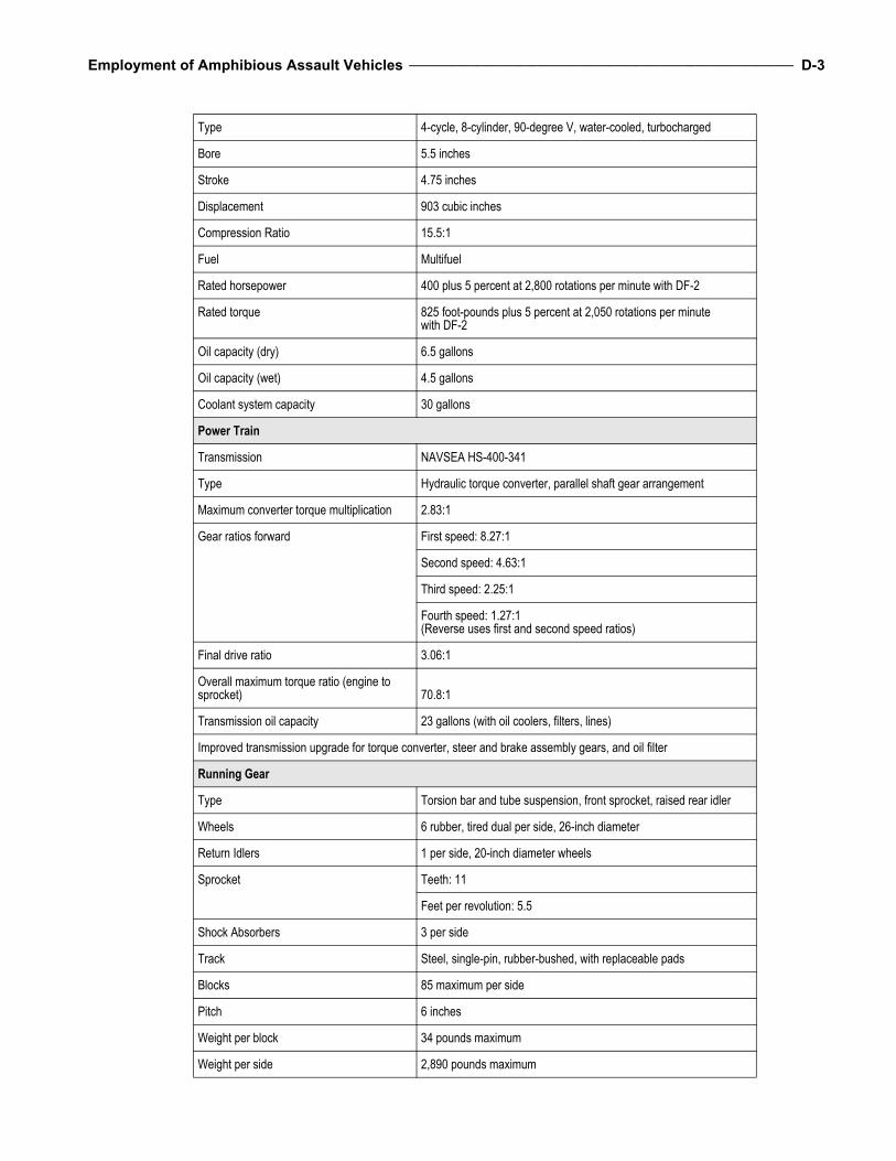
Employment of Amphibious Assault Vehicles _______________________________________________________________ D-3
Type 4-cycle, 8-cylinder, 90-degree V, water-cooled, turbocharged
Bore 5.5 inches
Stroke 4.75 inches
Displacement 903 cubic inches
Compression Ratio 15.5:1
Fuel Multifuel
Rated horsepower 400 plus 5 percent at 2,800 rotations per minute with DF-2
Rated torque 825 foot-pounds plus 5 percent at 2,050 rotations per minutewith DF-2
Oil capacity (dry) 6.5 gallons
Oil capacity (wet) 4.5 gallons
Coolant system capacity 30 gallons
Power Train
Transmission NAVSEA HS-400-341
Type Hydraulic torque converter, parallel shaft gear arrangement
Maximum converter torque multiplication 2.83:1
Gear ratios forward First speed: 8.27:1
Second speed: 4.63:1
Third speed: 2.25:1
Fourth speed: 1.27:1(Reverse uses first and second speed ratios)
Final drive ratio 3.06:1
Overall maximum torque ratio (engine to sprocket) 70.8:1
Transmission oil capacity 23 gallons (with oil coolers, filters, lines)
Improved transmission upgrade for torque converter, steer and brake assembly gears, and oil filter
Running Gear
Type Torsion bar and tube suspension, front sprocket, raised rear idler
Wheels 6 rubber, tired dual per side, 26-inch diameter
Return Idlers 1 per side, 20-inch diameter wheels
Sprocket Teeth: 11
Feet per revolution: 5.5
Shock Absorbers 3 per side
Track Steel, single-pin, rubber-bushed, with replaceable pads
Blocks 85 maximum per side
Pitch 6 inches
Weight per block 34 pounds maximum
Weight per side 2,890 pounds maximum

D-4 _____________________________________________________________________________________________________ MCWP 3-13
Water Propulsion
Water Jet Pumps Capacity: 14,000 gallons per minute
Thrust: 3,025 pounds static
Quantity: 2
Location: port and starboard, aft
Steering and reverse Jet deflectors
Electrical
Nominal voltage 24 volts, direct current
Generator 300 ampere, 28 volts, direct current battery:
Volts: 12
Type: 6 cell, terminal, lead
Quantity: 4
Communication
Control monitor C-11291 2
Radio frequency amplifier AM-7238 1
Vehicular amplifier adapter AM7239 1
Mount MT-6352 1
Loudspeaker LS-671 2
Receiver-transmitter RT-1523 2 (AN/VRC-89)
Antennas AS-3916 2
Audio frequency amplifier AM-7162 1
Intercom control box C-11133 4
Armament and Ammunition
M60D machine gun, pintle-mounted Ammunition: 7.62 millimeters; 400 rounds
M16 A2, 5.56-millimeter rifle, quantity 5 (troop issue)
Armor
Permanent hull Aluminum armor plate
Ramp outer: 1.000 inch
Ramp inner: 0.500 inch
Sides: 1.750, 1.395, and 1.222 inches
Top: 1.185 inches
Bottom: 1.185 inches
Stern: 1.395 inches

Employment of Amphibious Assault Vehicles _______________________________________________________________ D-5
Fire Extinguishers
Automatic fire sensing suppression system:
Cylinders 3
Location Aft engine compartment bulkhead and forward starboard stanchion
Capacity 7 pounds each, Halon 1301
Sensors 4
Portable:
Cylinders 1
Location Starboard, aft
Capacity 5 pounds carbon dioxide
Manual Fire Suppression System:
Troop Compartment Cylinders: 1
Location: port sponson
Capacity: 17 pounds each, Halon 1301
Engine Compartment Cylinders: 2
Location: driver's compartment and aft engine compartment bulkhead
Capacity: 7 pounds each, Halon 1301 each
Vision and Sighting Equipment
Driver's Station:
Direct vision blocks 7
Driver's night vision device AN/VVS-2(V)1A: 1 or AN/VAS-5A(V)6: 1
Commander's station:
Direct vision blocks 7
Periscope, M27 1
Auxiliary station, direct vision blocks 9
Ramp, direct vision block 1
Recovery Equipment
Electrical power source: Generator (engine driven)
Rating 12.5 kilovolt amperes, 0.8 power factor, 60-cycle, three-phase, four-wire
Output 120 volts alternating current single-phase and 220 VAC three-phase
Speed 3,600 rotations per minute
Hydraulic power source: Pump (engine driven)
Pressure 2,200 pounds per square inch
Delivery rate at 1,800 engine rotations per minute and 1,680 pump rotations per minute
Section 1: 32.0 gallons per minute
Sections 2 and 3: 20.0 gallons per minute
Section 4: 9.0 gallons per minute

D-6 _____________________________________________________________________________________________________ MCWP 3-13
Air compressor (two-stage reciprocating):
Piston displacement 14.4 cubic feet per minute
Operating pressure 145 to 175 pounds per square inch gauge
Speed 720 rotations per minute
Welder power supply: Miller Maxtron 300
Input voltage (single/three phase) 230 - 460 volt alternating current
Voltage range in constant voltage mode (metal inert gas) 10 - 36 volts, direct current
Amperage range in constant current mode (tungsten inert gas/stick) For single-phase: 3 - 375 ampere
Open-circuit voltage in constant current mode: 80 volts, direct current (maximum)
Hydraulic crane:
Horizontal reach maximum boom load capacity 6,000 pounds
Boom working angle 0 to 65 degrees
Crane swing-moment capacity 14,000 foot-pounds
Crane moment rating 129,000 foot-pounds
Crane swing speed (azimuth rotational speed) 1.5 rotations per minute
Crane winch:
Single-Line Rating 6,000 pounds
Line speed First layer: 25.6 feet per minute
Second layer: 31.2 feet per minute
Third layer: 36.7 feet per minute
Wire rope Diameter and classification: 1/2 inch, 6 by 19 wire
Breaking strength: 23,000 pounds
Length: 85 feet
Recovery winch:
Line pull, low speed Bare drum: 30,000 pounds
Full drum: 18,200 pounds
Line pull, high speed Bare drum: 6, 830 pounds
Full drum: 4,140 pounds
Line speed, low speed Bare drum: 22 feet per minute
Full drum: 36 feet per minute
Line speed, high speed Bare drum: 97 feet per minute
Full drum: 160 feet per minute

Employment of Amphibious Assault Vehicles _______________________________________________________________ D-7
Wire rope Diameter and classification: 3/4 inch, 6 by 37 wire
Breaking Strength: 48,600 pounds
Length: 278 feet
Navigation Equipment
(None is integrated/organic to the AAV7A1.)
Other
Capability enhancements, chemical agent resistant coatings
Special mission kits Visor kit, NAVSEA P/N 2587015
Winterization kit, NAVSEA P/N 5433242
Production FMC Corporation
Date first prototype: 1979
Date first production vehicle: 1983

APPENDIX E. RESCUE PROCEDURESFOR DISABLED AAVS
In any rescue or retrieval operation, the protection of the lives of personneltakes priority over the salvage of disabled vehicles. Vehicles disabled in thesurf zone fall under the cognizance and control of the AA unit leader in chargeof the operation. Detailed rescue responsibilities are designated in unit SOPsand/or the OPORD. While waterborne AAV rescue procedures cannot be estab-lished for all circumstances, this appendix includes emergency signals, rescueteams, transfer of passengers, retrieval of man overboard, towing, special safetyconsiderations, sinking AAV procedures, and crewmen’s responsibilities. Thefollowing factors may influence the rescue of waterborne AAVs:
Urgency of the situation aboard the vehicle. Condition of the sea. Number and experience of the passengers embarked. Skill of the AAV crew. Availability of rescue means or craft.
Emergency Signals
Radio communications concerning disabled, waterborne AAVs will take prece-dence over other communications. If the radio is inoperable, the disabled vehi-cle will use the following visual distress signals:
Inoperable (day)—Display November flag attached to a vertical boat hook. Sinking (day)—Wave November flag continuously. Fire red flare into theair.
Inoperable (night)—Turn on and point searchlight or battle lantern vertically.If signal fails, fire one white flare into the air.
Sinking (night)—Turn on and point searchlight or battle lantern vertically.Fire red flares into the air.
Rescue Teams
Waterborne operations will be conducted with a designated rescue team (RT).The RT can be a part of the waterborne operation; the RT is not a separate
E-2 _____________________________________________________________________________________________________ MCWP 3-13
entity required to remain on the beach. Regardless of the size of the unit, theunit commander will specifically assign at least one AAV for the RT. Its tacti-cal number and location will be specified in the OPORD. The embarked RTshould have two first class swimmers and a corpsman. The AAV designated forthe RT should not carry a full load of embarked personnel or cargo, because itmust be capable of receiving personnel transferring from the disabled vehicle.The RT equipment should include a matched set of nylon towing lines (withspliced eyelets) and one ring buoy with 50 feet of line attached to mark the dis-abled vehicle in case it sinks. If a ring buoy is not available, an empty water canor life jacket is suitable with the equivalent length of rope to attach to the dis-abled vehicle.
During waterborne operations, each AAV is a potential safety vehicle and canassist and tow the closest disabled vehicle. The initial aim of the rescuing vehi-cle is the safety and recovery of embarked passengers and crew. Embarked per-sonnel will be loaded into the designated RT vehicle before recovery of thedisabled vehicle is attempted. Vehicles will not be towed with embarked troopson board unless a greater physical hazard would be posed by the sea conditionor tactical situation in the transfer of embarked personnel to another vehicle.
Transfer of Passengers at Sea
The greatest hazard to AAV crew and passenger safety at sea is the danger of avehicle sinking. If a vehicle’s watertight integrity becomes questionable, theembarked passengers should be immediately evacuated. Bow-to-bow, side-to-side, and rough sea transfer methods are used to transfer troops.
Bow-to-Bow Transfer
The bow-to-bow transfer is the preferred method of troop transfer from a dis-abled AAV. See figure E-1. Before approach, the safety vehicle’s bow planesmust be lowered and fender material placed in a position to prevent bow dam-age. Both vehicles will open starboard cargo hatches, which will allow embark-ing/debarking troops to stand on the port cargo hatch and use the radio grill toclimb up or down. After approach, the AAVs will be held in position by crew-men using boat hooks or hand-held lines until troop transfer is complete.
Side-to-Side Transfer
An alternate method of troop transfer is the side-to-side transfer. See figure E-2.This method can be used with either an AAV or a Navy safety boat. The rescuingvehicle will come along the leeward side of the disabled AAV. The AAVs willdock port side to port side using fender material secured to the side of the AAVs.Personnel will exit the disabled vehicle by climbing up the radio grill and steppingacross the center bar to the port cargo hatch and then onto the receiving vehicle.

Employment of Amphibious Assault Vehicles _______________________________________________________________ E-3
Dunnage
Rough Sea Transfer
Direct transfers should not be attempted in high swells or within the surf zone.In such cases, personnel will enter the water in pairs and swim to the safetyvehicle. During transfer operations, the vehicle commander ensures AAVs arein neutral and water-jets are not used. The following rescue procedures are usedin rough seas:
Personnel will exit through the starboard cargo hatch, move to the other sideof the AAV, and prepare to swim to the safety vehicle.
Dunnage
Figure E-1. Bow-to-Bow Transfer Diagram.
Figure E-2. Side-by-Side Transfer Diagram.

E-4 _____________________________________________________________________________________________________ MCWP 3-13
Safety vehicle will be positioned between 25 and 50 meters away from thedisabled vehicle on the windward side (wind blows from the safety vehicletoward the disabled vehicle). This prevents the disabled AAV from comingdown on personnel as they swim to the safety vehicle.
Troops embarked on the disabled vehicle will inflate lifejackets, jump (notdive) into the water, stay with their assigned buddy, and swim or paddle tothe safety vehicle. The vehicle crew chief will dispatch personnel in anorderly manner.
Personnel will use the port and starboard cargo hatches to exit if the disabledvehicle is in danger of sinking. They will move quickly to topside and transferto the safety vehicle. If a safety vehicle is not available, personnel must swimaway from the disabled AAV.
Retrieval of Man Overboard
Rescue personnel will use a boat hook, life ring or towline to retrieve a manoverboard. Only as a last resort should a man from the safety vehicle enter thewater. If required, the rescuer will jump with arms and legs spread wide to keephead above water and eyes on the man. The vehicle, with tracks secured, shouldbe maneuvered close to the man in the water. If necessary, mouth-to-mouthresuscitation will commence as the victim is brought aboard.
Towing a Floating AAV
To prepare for towing, the crew of the disabled AAV sets an operable engine at1,800 RPMs. Hatches and plenums are closed, watertight integrity is insured,the transmission is placed in the neutral position, and the mode selector switchis set in the water/track mode. If the hydraulic bilge pumps are not functioningdue to an engine failure, the master switch is left on and the electric bilgepumps are activated. Before towing of the disabled AAV commences, the crewon the disabled vehicle attempts repairs, and if unsuccessful, the AAV is takenunder tow. The preferred method of towing an AAV is stern to bow, and thoseprocedures are as follows:
The safety vehicle should be positioned with the stern to the bow of the vehi-cle being towed. An alternative method involving docking the sterns of bothvehicles can be used when the integrity of the disabled vehicle’s plenums isquestioned.
The disabled vehicle provides the towlines. One end of each of the two 50-foottowlines are passed through the eyes of the aft mooring bits of the towing vehi-cle and secured to the quick release mechanism.
The port towline is attached through the starboard mooring bit, and the star-board towline is attached through the port mooring bit. In this way, the tow-lines are crossed, affording great control over the disabled vehicle once it is

Employment of Amphibious Assault Vehicles _______________________________________________________________ E-5
under tow. Once the two lines are connected, care must be taken to avoidpossible backlash injury.
The crew of the disabled vehicle secures hatches. The crew of the towingvehicle positions its hatches as follows:
The driver’s hatch is locked at the combat lock.The troop commander’s hatch is closed.The crew chief positions the turret to face aft and secures the hatch.
The towing vehicle crew chief places the vehicle ax in the turret for readyuse to disconnect towlines should the quick release mechanism fail.
The crew chief of the towing vehicle looks aft from inside the turret to watchthe condition of the disabled vehicle. The third crewman is stationed inside atthe rear of the towing vehicle to observe the proceedings from the visionblock. Crewmen should be evacuated from disabled AAVs that are withoutelectrical power and have lost watertight integrity.
Hatches should be kept closed on both vehicles until the AAV is towedthrough the surf zone to the high watermark on the beach and there is slack inthe lines.
In addition to the above policy, when towing a disabled AAV with anotherAAV, the appropriate naval authority will determine the final course ofaction. Disabled AAVs should be towed to the nearest safe haven (amphibi-ous ship or beach).
Wet-well ships are the preferred platform of amphibious ship. See appendix I forrecovery procedures. Disabled AAVs will be towed through the surf at a 90-degreeangle to the surf line and to a point on the beach where—
Neither vehicle has tracks in the water. Collision between the vehicles is impossible. Disabled AAV will not roll back.
When the point on the beach has been reached, tow cables can then replacetowlines. The rescuing vehicle may attempt to tow the disabled vehicle throughthe surf zone and to the high watermark of the beach, thereby eliminating thenecessity of hooking up land towing lines in the surf zone. If the beach gradientis steep or surf conditions permit, the vehicle may stop before the high water-mark and connect tow cables.
Special Safety Considerations
The following special safety measures should be considered for water operations:
When conducting AAV water operations, the third crewman must ride in thetroop compartment of the AAV to constantly monitor watertight integrity.

E-6 _____________________________________________________________________________________________________ MCWP 3-13
Planning for water operations should include alternate plans and timed evac-uation drills.
When planning for water operations in an emergency, water temperature, seastate, and available safety vehicles/vessels must be considered to determinethe best type of evacuation to employ; brief the evacuation method; and prac-tice these drills.
When evacuation of troops and crew is required in a combat environment,the crew chief, with advice from the troop commander, must quickly decidewhether to retain gear/weapons.
After the command is given to evacuate the AAV, crewmen will not remainin a disabled AAV that is sinking and without power.
Only the most experienced AAV crews should attempt the recovery of anAAVR7A1 because of its unique weight and balance considerations.
Sinking AAV Procedures
Although the current series of AAVs is the most seaworthy, rapid vehicle sink-ing may occur, making it impossible to evacuate embarked personnel before thevehicle slips under the surface of the water. Crew and passengers should staywith the sunken vehicle if it remains buoyant because of wave action in the surfzone and await recovery by another AAV. If the vehicle settles in the surf zoneand is completely grounded where the water depth and wave action do not cre-ate a buoyant effect, crew and passengers should—
Seek air pockets formed in the troop compartment. Open hatches after internal and external pressures have equalized. Abandon the vehicle in pairs over the side in a direction that is parallel to thebeach, but not leeward of the vehicle.
Inflate life preservers after leaving the vehicle.
Crewmen’s Responsibilities
Based on the status of the disabled AAV, the crew of the disabled vehicle willhave the responsibilities outlined in table E-1.

Employment of Amphibious Assault Vehicles ________________________________________________________________ E-7
Table E-1. Crewmen’s Responsibilities.
Status of Disabled
AAV Crew Chief Troop Commander Driver CrewmanDead engine (with battery power)
Display November flag during the day or fire white flare and display vertical light beam in the air at night.Inform platoon commander of the situation by radio.Troubleshoot the AAV systems to attempt to regain power.Inform troop commander of the situation and steps being taken.Check operation of electric bilge pumps.Keep hatches closed to prevent taking in excess water.Prepare to receive tow or transfer troops.Supervise transfer of troops to safety vehicle.
Obey crew chief’s commands.Give a warning order to the troops to prepare for evacuation as directed by the crew chief.Assist crew in maintaining discipline.
Keep master switch on.Keep electric bilge pumps on.Shift to neutral.Check fuel shutoff lever to ensure it is in an upright position.Check fuel shutoff valve on deck behind driver.Attempt to restart engine.Continue attempts to restart engine (conserve electricity).Disconnect hydrostatic steer unit if the engine will not start, and prepare for tow and/or transfer of troops.
Check constantly for watertight integrity, and report compromises immediately to the crew chief.Help maintain discipline in the troop compartment.Assist topside with troop transfer.
Dead engine (without battery power)
Display November flag during the day or fire white flare and use battle lantern to display vertical light beam in the air at night.Troubleshoot the AAV systems and attempt to regain power.Inform the troop commander of the situation and steps being taken.Keep hatches closed to prevent taking in excess water.Prepare to receive tow and to transfer troops.Supervise the transfer of troops to safety vehicle or the water.
Obey crew chief’s commands.Inform troops of the situation, and prepare for troop transfer or vehicle evacuation.Assist crew in maintaining discipline.
Shift engine throttle to neutral.Troubleshoot the AAV systems to attempt to regain power.Disconnect the hydrostatic steer unit, and prepare for tow and transfer of troops.
Check constantly for watertight integrity, and report leaks immediately to the crew chief.Help maintain discipline in the troop compartment.Assist topside with troop transfer.
Sinking (with power)
Wave the November flag during the day or fire red star distress signal in the air over the vehicle, and direct the beam of the battle lantern vertically at night.Notify the platoon commander by radio.Open cargo hatches with assistance from crewman.Order evacuation of embarked troops/execute evacuation procedures.Order crew to abandon vehicle.Debark the vehicle after personnel have been evacuated.
Obey crew chief’s commands.Assist crew in maintaining discipline.
Keep engine, electric bilge pumps, and headlights on.Lower the seat and evacuate the vehicle through the driver’s hatch when ordered by the crew chief.
Check constantly for watertight integrity, and report compromises immediately to the crew chief.Help maintain discipline in the troop compartment.Assist crew chief in opening cargo hatches.Assist passengers topside.Notify the crew chief when embarked troops have been evacuated.Evacuate the vehicle when ordered by the crew chief.
Sinking (without power) constitutes an emergency
Wave the November flag during the day, and fire red star distress signal in the air over the vehicle and display vertical light beam in the air at night. Notify platoon commander of the situation via voice or flashing light.Order preparations for evacuation of embarked troops. Open cargo hatches with assistance from crewman.Execute evacuation procedures.Order crew to abandon vehicle.Debark the vehicle after personnel have been evacuated.
Obey crew chief’s commands.Assist crew in maintaining discipline.
Keep master switch on.Shift engine throttle to neutral.Troubleshoot the AAV system and attempt to regain power.Lower the seat and evacuate the vehicle through the driver’s hatch when ordered by the crew chief.
Check constantly for watertight integrity and report compromises immediately to the crew chief.Help maintain discipline in the troop compartment.Assist crew chief in opening cargo hatches.Assist passengers topside.Notify the crew chief when embarked troops have been evacuated.Evacuate the vehicle when ordered by the crew chief.

APPENDIX F. LANDING DOCUMENTS
MCWP 5-1, Marine Corps Planning Process, and NWP 3-02.1, Ship-To-ShoreMovement, contain instructions for the preparation of landing documents. Thedocuments in this appendix are specific to AA units.
Documents Page
Landing Diagram. . . . . . . . . . . . . . . . . . . . . . . . . . . . . . . . . . . . . . . . . . . . . . F-2Landing Craft and Amphibious Vehicle Assignment Table . . . . . . . . . . . . . F-3Serial Assignment Table . . . . . . . . . . . . . . . . . . . . . . . . . . . . . . . . . . . . . . . . F-4Landing Sequence Table . . . . . . . . . . . . . . . . . . . . . . . . . . . . . . . . . . . . . . . . F-5Assault Schedule . . . . . . . . . . . . . . . . . . . . . . . . . . . . . . . . . . . . . . . . . . . . . . F-6Amphibious Vehicle Availability Table . . . . . . . . . . . . . . . . . . . . . . . . . . . . F-7Amphibious Vehicle Employment Plan . . . . . . . . . . . . . . . . . . . . . . . . . . . . F-8

F-2 _____________________________________________________________________________________________________ MCWP 3-13
Landing Diagram
The landing diagram is the graphic means of illustrating the plan for ship-to-shore movement of the scheduled waves of an assault unit. The landing forma-tion and type of landing craft or vehicles comprising the wave are normallydetermined by the commander, amphibious task force (CATF), and the com-mander, landing force (CLF), based on naval capabilities for supporting theplan and upon recommendations from the AAV unit leader and AAV availabil-ity. AAVs depicted in the landing diagram portray the boat teams embarked onAAVs numbered from left to right in each wave. For example, number 5-5would be the fifth vehicle from the left in the fifth wave. For planning pur-poses, the landing diagram should allow dispersion of at least 25 (day)/50(night) meters between AAVs, at least 3 minutes between AAV waves, and atleast 10 minutes between boated waves, unless landing in column. This pro-vides room for AAVs to move off the beach before the next wave and forboated waves to extract from the beach to the boat return lane.
Beach Red 1H-hour 0530 localScheduled Waves Wave CompositionWave 0 01 02 03 04H-3 minutes XL X XL X
Wave 1 1st and 2d Platoons, Company G, BLT 2/5H-hour 1-1 1-2 1-3 1-4 1-5 1-6 1-7
X X X (X) X X XWave 2 3rd Platoon and Mortars, Company G, BLT 2/5 Command GroupH+3 minutes 2-1 2-2 2-3 2-4 2-5 2-6 2-7 2-8
X X X X (X) X C RWave 3 Weapons Company, BLT 2/5H+6 3-6 3-4 3-2 3-1 3-3 3-5
U U U (U) U UX = AAVP7XL = AAVP7 W/MK-154C = AAVC7
R = AAVR7U = LCU(X) = wave commander

Employment of Amphibious Assault Vehicles _______________________________________________________________ F-3
Landing Craft and Amphibious Vehicle Assignment Table
The landing craft and amphibious vehicle assignment table shows the break-down of troop units into boat teams and the assignment of boat teams to wavesor to a serialized element of an nonscheduled unit. This table and the debarka-tion schedule furnish ship commanding officers with information for the debar-kation of troops. AA commanders advise supported commanders and staffswith respect to vehicle capacity and methods of employment.
Craft Number Personnel and Material
Boat Spaces
Beach Red 1 Formation
1-1AAVP7
Company Commander, Company GMessenger Radio Operator81-millimeter FO Team with 1 Radio OperatorFAC with 1 Radio OperatorWeapons Platoon Commander, Company GCompany 1st Sergeant, Company G
1 1 2 2 1 1 8
Column
X 1-1
1-2AAVP7
Platoon Commander, 1st Platoon, Company GMessenger Radio Operator1st Squad, 1st Platoon, Company GCorpsman
1 13 1 2 17
X 1-2
1-3AAVP7
Platoon Guide, 1st Platoon, Company G2d Squad, 1st Platoon, Company GCorpsman1st Machine Gun Team, Weapons Platoon, Company G
1 13 1 3 18
X 1-3
1-4AAVP7
Platoon Sergeant, 1st Platoon, Company G3d Squad, 1st Platoon, Company GCorpsman1st Assault Team, Weapons Platoon, Company G
1 12 1 2 16
X 1-4
1-14AAVC7
BLT 2/5 CommanderS-3S-2NGF Liaison OfficerAir OfficerCompany Commander, Weapons Company (FSC)Artillery Liaison OfficerRadio OperatorsCommunications Technician
1 1 1 1 1 111 3 11
C 1-14
X = AAVP7 C = AAVC7 R = AAVR7

F-4 _____________________________________________________________________________________________________ MCWP 3-13
Serial Assignment Table
A serial is a group of troop units, supporting units, and their equipmentembarked in the same ship that will be landed on the same beach at the sametime. AAVs may be used to transport a serial.
The table is prepared and issued at LF level. AA unit personnel advise as to capacities of AAVs and potential problems with loading AAVs aboard ships.
Serial Number Unit
Number of
Personnel
Material Equipment
VehiclesNumber and Type of Craft
Parent Ship Remarks
A Company (Rein), 1st Battalion, 4th Marines (1401-1402)
1401 Co A (-) 140 7 AAVP71 AAVC7
LST-1179 1st WaveBeach Red 1
1402 3d Platoon (Rein)Company C
126 2 81-mm mortars
7 AAVP7 LST-1179 2d Wave Beach Red 1
B Company, 1st Battalion, 4th Marines (1403-1404)
1403 Company B (-) 133 7 AAVP7 LSD-49 1st WaveBeach Blue 1
1404 3d Platoon,Company B
120 7AAVP71 AAVR7
LSD-36 2d WaveBeach Blue 1

Employment of Amphibious Assault Vehicles _______________________________________________________________ F-5
Landing Sequence Table
Detailed plans for the ship-to-shore movement of nonscheduled units are setforth in the landing sequence table. The LF and naval agencies use this table asthe principal document in executing and controlling the movement of non-scheduled units. The completed table is prepared at LF level, and subordinateunits extract applicable portions. AA commanders advise as to which vehiclebest meets this LF requirement, where it would be best embarked, and otherconsiderations pertaining to AAV employment.
Unit ElementSerial
Number
Carrier Ship
Beach RemarksNumber TypeG Company (-), 2/5 3d Platoon 910 3 AAV LSD-36 Red
A Company (-), 2d Tank Battalion
3d Platoon 911 3 LCU LSD-36 Red
B Company, 2d Tank Battalion
1st and2d Platoons
909 3 LCU LSD-37 Blue
B Company (-), 2d Tank Battalion
3d Platoon 908 3 LCU LSD-37 Blue
1/10 A Battery 1013 7 LCM LPD-5 Red
1/10 B Battery 1014 7 LCM LPD-5 Red
C Battery 1015 7 LCM LPD-1 Red
1/10 Headquarters Battery
1016 3 LCM LPD-5 Red
D Battery 1023 8 LCM LPD-4 Blue
Division Tactical CP 401 4 LCM LHA-1 Blue
A Company (-), 2d Engineer.
1st Platoon 105 3 AAV LSD-28 Red

F-6 _____________________________________________________________________________________________________ MCWP 3-13
Assault Schedule
An assault schedule is prepared and issued to prescribe the composition andtiming of waves landing over designated beaches. The schedule is prepared atLF level, and subordinate units extract applicable portions. The schedule showseach scheduled wave number, the time that landing craft or AAVs are sched-uled to land, the craft/vehicle serial numbers, and the units landing.
Wave Time
BeachRed 1 Red 2
Craft/Vehicle Serial Number Unit
Craft/Vehicle Serial Number Unit
1 H-Hour 12 AAVP71426
Company A 1/7 12 AAVP71426
Company E 2/7
2 H+5 12 AAVP71427
Company B 1/7 12 AAVP71477
Company F 2/7
3 H+10 6 AAVP71430
Company C 1/71st and 2d Platoons
6 AAVP71480
Company G 2/71st and 2d Platoons
4 H+15 6 AAVP71431
Company C (-) 1/73d Platoon
5 AAVP71481
Company G (-) 2/73d Platoon
5 H+20 3 LCU2351
Company A (Rein)3d Tank Battalion
4 LCM-81482/1484
Weapons Company 2/7
6 H+27 8 LCVP1432-1434
Weapons Company 1/7 8 LCVP1483/1485
H&S Company (-) 2/7
On-Call Waves
Report to PCS at H+40 1 LCM-82 LCM-61 LCVP2305/2306
Shore Party Team 1 1 LCM-82 LCM-81 LCVP2307/2308
Shore Party Team 2
Report to PCS at H+45 2 LCVP Floating Dumps 2 LCVP Floating Dumps

Employment of Amphibious Assault Vehicles _______________________________________________________________ F-7
Amphibious Vehicle Availability Table
The amphibious vehicle availability table is a list of AAV numbers and typesavailable to the LF. The LF prepares the amphibious vehicle availability tableusing data derived from consultation with the AAV commander. The tableincludes the number and type of vehicles embarked in each ship and identifiesthe AA unit involved.
Ship AAV UnitNumber and Type of AAV
RemarksAAVP7 AAVC7 AAVR7LST-1179 3d Platoon, Company B, 3d AA Battalion 13 1 1
LSD-36 1st Platoon, Company A, 3d AA Battalion2d Battalion, Company A, 3d AA Battalion2d Platoon, Company D, 3d AA Battalion
131216
111
1 2 MK-154 LMC Kits
LSD-37 Company C, 3d AA Battalion 43 3 1
LPD-1 1st Platoon, Company D, 3d AA Battalion 16 1 1 2MK-154 LMC Kits
Total 113 8 4

F-8 _____________________________________________________________________________________________________ MCWP 3-13
Amphibious Vehicle Employment Plan
The amphibious vehicle employment plan shows the planned employment ofamphibious vehicles, including their employment after landing. The CLF’s staffprepares the amphibious vehicle employment plan when shipping availability isconfirmed and after the assault schedule is completed. The AA commandershould be intimately involved in the completion of this document, as it controlsAAV employment. The plan includes identification of ships in which vehiclesare embarked, number and type of amphibious vehicles employed, wave inwhich the vehicles will land, and destination of vehicles.
Origin
Number and Type of Amphibious Vehicle
Wave Destination RemarksAAVP7 AAVC7 AAVR7 LARCLSD-36 7 1 Red 1 1st and 2d Platoons
Company A 1/7
LSD-36 6 1 1 2 Red 1 3d Platoon Company A 1/7
LSD-38 7 3 Red 1 1st and 2d Platoons Company B 1/7
LSD-38 6 1 1 4 Red 1 3d Platoon Company B 1/7
Second Trip
3d Platoon, Company B, 3d AA Battalion
12 LHA-1 Transport Company C 1/7 to Red 1
2d Platoon, Company B, 3d AA Battalion
12 LPD-1 To land artillery ammunition as needed

APPENDIX G. GRID REFERENCE SYSTEM
The Navy uses the grid reference system to control the ship-to-shore move-ment of landing craft. Composed of a time/space overlay known as a boat lanediagram and a series of standard radio transmissions known as grid positionmessages, the system enables a wave of landing craft [AAVs] to—
Navigate the boat lane and land in the correct position. Land ashore at the proper time as specified by the landing timeline.
Boat Lane Diagram
The boat lane diagram is an approximate picture of the boat lane from the launcharea or in the case of an underway launch, from the line of departure (LD) to thebeach. Longitudinal lines in the diagram divide the lane into three sections: left (L),center (C), and right (R). Left and right sections are each 40 percent of the totalwidth; the center section is 20 percent of the total width. Lane positions aredescribed by L, C or R followed by a one- or two-digit number. A double lettersuch as RR or LL indicates positions outside the lane. The boat control team has thegridiron boat lanes plotted to scale in the combat information center (CIC).
The Navy tracks grid positions, which are the locations of the center of waves, byusing the boat lane diagram. By using radar to track the landing craft, the Navycan track the wave. As the wave changes course and speed, Navy personnel plotthese changes as a series of dots representing the center of the wave on the boatlane diagram laid out in the CIC. The wave’s position in the boat lane is based onthe distance from the shore and the location relative to the center of the lane.
Boat Lane Diagram
Beach Red One0 02 14 26 38 4
Yards from LD to beach 10 5 Minutes away from the beach12 614 718 8
LD 20 10 LD200 100 200----------500 yards---------
LL L C R RR

G-2 _____________________________________________________________________________________________________ MCWP 3-13
Grid Position Messages
To guide the landing craft waves ashore, the Navy has devised a series of shortstandardized radio transmissions.
Message Parts
Each transmission has six parts, and they follow each other in sequence.
Wave Call SignThe call sign of the wave consists of the wave number and the designated beachfor that wave. The following example refers to the first wave going to BeachRed One:
Message IdentifierThe message identifier is the ship’s call sign and the words Grid Posit (short forgrid position). For example:
Location of Center Vehicle in the Boat LaneThe location of the center vehicle in the boat lane is the wave’s physical loca-tion as it is plotted in the CIC. The orientation to the center of the wave is givenfirst. The following example indicates a wave centered in the left side of theboat lane:
The following message indicates a wave centered outside and to the left of theboat lane:
Distance of the Wave from the BeachThe distance the center vehicle is from the beach will be reported as a numberfollowing the location. The following example indicates a wave that is cen-tered in the boat lane 1,600 yards from the beach:
One Red One.
One Red One, this is Red Catskill, Grid Posit.
One Red One, this is Red Catskill, Grid Posit, Lima.
One Red One, Grid Posit, Lima Lima.
One Red One, this is Red Catskill, Grid Posit, Charlie, 16.

Employment of Amphibious Assault Vehicles ______________________________________________________________ G-3
Time in Relation to the Landing ScheduleThis is how the wave is proceeding in respect to the timeline for the movement.On time, early or late are the three key phrases used to express time in relationto the landing schedule. This portion is followed by a time in minutes. The fol-lowing example indicates a wave that is right of center in the boat lane, 1,200yards from the beach, and 2 minutes behind schedule or late:
CorrectionsThis is direction from the Navy on how to correct the heading of the wave. Thesecorrections should be transmitted immediately to the wave so it may correct itsposition. Usually, late time corrections are given only if the wave is more than 1minute late. Corrections can take several forms. Examples would be:
Assembled Message
Once the parts are assembled into one grid position message, it will tell thewave commander exactly where the wave is in the boat lane and whether or notit needs to correct its heading. The following example indicates Wave Onegoing to Beach Red One is in the center of the boat lane, 1,600 yards from thebeach, and they are behind schedule 1 minute:
The following example indicates Wave Two going to Beach Red One is cen-tered in the left side of the boat lane, 1,400 yards from the beach, and they arelate 2 minutes. They are directed to vector right 5 degrees and speed up.
Procedures
During amphibious operations, the primary control ship (PCS) and AAVwaves must track the grids for units involved. The following procedures ensuresituational awareness and that the waves land at the correct location on theshore as scheduled:
Upon launching from the ship, the wave will check in with the PCS on BoatBravo. Boat Bravo is used to control waves from the time it leaves the shipuntil it crosses the LD. Since AAVs are normally launched at or in closeproximity to the LD, Boat Bravo will probably not be used for long.
One Red One, this is Red Catskill, Grid Posit, Romeo, 12, Late 2.
Vector Right 10 Degrees, Speed Up.
Vector Left 5 Degrees, Slow Down.
One Red One, this is Red Catskill, Grid Posit, Charlie, 16, Late 1, Out.
Two Red One, this is Red Catskill, Grid Posit, Lima, 14, Late 2, Vector Right 5 Degree, Speed Up, Over.

G-4 _____________________________________________________________________________________________________ MCWP 3-13
Once the wave crosses the LD, AAVs will switch to Boat Alpha to receivegrid positions from the PCS.
The PCS tracks the wave and fixes the position of each wave on the boat lanediagram in CIC.
The boat control team then transmits to the AAV wave commander theAAV’s position in the prescribed format.
After receiving a grid position message that indicates the wave is not in thecenter of the lane and or is not progressing along the lane according to sched-ule, the wave guide officer (WGO) corrects the position and movement ofthe wave.
Control officers will supplement grid positions with vectors and early or latewave-timing information as necessary.
Normally, grid positions are transmitted every minute from the LD to 20 yardsfrom the beach unless corrective action is required, in which case they aretransmitted more frequently. In low visibility, positions will be provided onceper minute from the LD to the beach.
The last 1,000 yards to the beach is run at full (battle) speed. To obtain full benefit from the grid, AAV wave commanders may plot theirposition each time the controlling station transmits it to obtain a track of thewave’s progress. The effects of wind and sea and/or taking incorrect head-ings can be determined and corrected on the next launch.
Once firm radio communications are established, grid positions are transmit-ted without requiring wave commanders to receipt. However, vectors shouldbe receipted. If the wave commander fails to receipt for orders by radio, thePCS will continue to transmit and request visual acknowledgment.
When the AAV wave commander’s vehicle contacts the bottom, the WGOwill transmit “Touchdown, touchdown, touchdown.” This notifies the PCSthat the vehicles have landed ashore.

APPENDIX H. AMPHIBIOUS SHIP AAV CAPACITIES
Ships of the amphibious fleet have varying internal characteristics that affecttheir AAV carrying capacities. The AAV carrying capacities listed below areapproximate maximum capacities for the classes of ships. For detailed plan-ning, the ship’s characteristics pamphlet must be consulted to determine thetrue capacity.
Ship Type and Class AAV Capacity
LSD-28/Thomaston Class:Well Deck 48
LSD-36/Anchorage Class:Well Deck 47
LSD-41/Whidbey Island Class:Well Deck 64
LSD-49/Harpers Ferry Class:Well Deck 27
LPD-1/Raleigh Class:Upper Vehicle LoadWell Deck
1420
LPD-4/Austin Class: Upper Vehicle LoadWell Deck
1620
LPD-17 Class:Well Deck 38
LST-1179/Newport Class:Tank Deck 23
LHA-1/Tarawa Class:Well Deck 79
LHD-1/Wasp Class:Well Deck 52
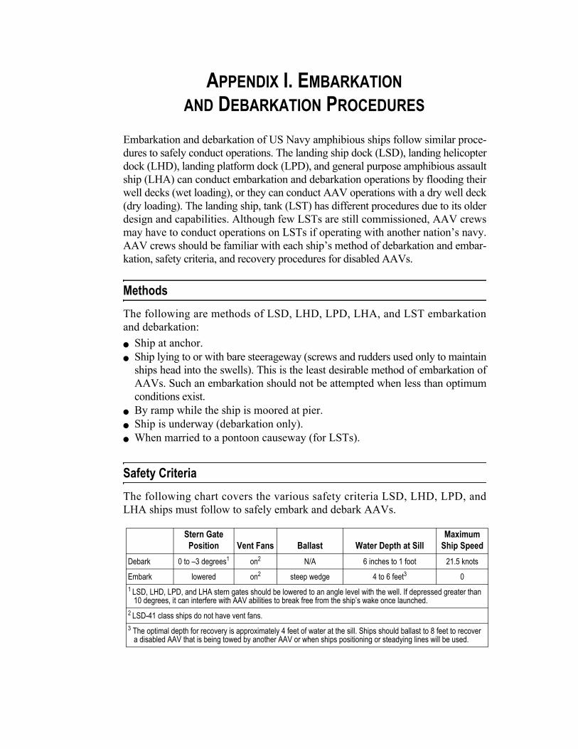
APPENDIX I. EMBARKATIONAND DEBARKATION PROCEDURES
Embarkation and debarkation of US Navy amphibious ships follow similar proce-dures to safely conduct operations. The landing ship dock (LSD), landing helicopterdock (LHD), landing platform dock (LPD), and general purpose amphibious assaultship (LHA) can conduct embarkation and debarkation operations by flooding theirwell decks (wet loading), or they can conduct AAV operations with a dry well deck(dry loading). The landing ship, tank (LST) has different procedures due to its olderdesign and capabilities. Although few LSTs are still commissioned, AAV crewsmay have to conduct operations on LSTs if operating with another nation’s navy.AAV crews should be familiar with each ship’s method of debarkation and embar-kation, safety criteria, and recovery procedures for disabled AAVs.
MethodsThe following are methods of LSD, LHD, LPD, LHA, and LST embarkationand debarkation:
Ship at anchor. Ship lying to or with bare steerageway (screws and rudders used only to maintainships head into the swells). This is the least desirable method of embarkation ofAAVs. Such an embarkation should not be attempted when less than optimumconditions exist.
By ramp while the ship is moored at pier. Ship is underway (debarkation only). When married to a pontoon causeway (for LSTs).
Safety CriteriaThe following chart covers the various safety criteria LSD, LHD, LPD, andLHA ships must follow to safely embark and debark AAVs.
Stern Gate Position Vent Fans Ballast Water Depth at Sill
Maximum Ship Speed
Debark 0 to –3 degrees1 on2 N/A 6 inches to 1 foot 21.5 knots
Embark lowered on2 steep wedge 4 to 6 feet3 01 LSD, LHD, LPD, and LHA stern gates should be lowered to an angle level with the well. If depressed greater than
10 degrees, it can interfere with AAV abilities to break free from the ship’s wake once launched.2 LSD-41 class ships do not have vent fans.3 The optimal depth for recovery is approximately 4 feet of water at the sill. Ships should ballast to 8 feet to recover
a disabled AAV that is being towed by another AAV or when ships positioning or steadying lines will be used.

I-2 ______________________________________________________________________________________________________ MCWP 3-13
The following chart covers the various safety criteria the LST ships must fol-low to embark and debark AAVs.
Embarkation Procedures
Embarking AAVs aboard an amphibious ship can be challenging and danger-ous, especially in higher sea states. The following steps should minimize risk:
The AA unit should maintain an interval of 50 to 75 meters between vehiclesin column to facilitate loading. For LSTs, ensure VIC-12 AAV antennas aretied down before embarking.
Before the signal to load, the first AAV should position approximately 100meters from the stern, depending upon operational conditions and schedules.
Just before receiving the signal to load, the first AAV driver will retract thebow plane.
Upon receiving the loading signal (i.e., green flag or green light) from theship’s crew, the AAV will approach the well bow on. The approach to the shipshould be made from directly astern in water-jets mode at 1,500 to 1,800 RPM.
The AAV driver will receive guidance, via hand signals, from well-deck guides. Approximately 30 meters before entering the well, the driver should placethe vehicle in first gear to engage the tracks.
As the AAV approaches the sill, the driver will slow down and proceed untilthe tracks touch down.
Once in solid contact with the deck, the driver will be ground-guided to pivotthe vehicle 180 degrees.
Directed by the ground guide, the driver will back the vehicle into its parkingspace. Although less desirable, AAVs may pivot when waterborne usingtheir water-jets and be ground-guided back into their parking spaces.
For LSTs, AAVs should not be turned when moving up the stern gatebecause the ramp will damage the AAV track. A driver failing to negotiatethe LST ramp should ease back into the water, reposition in water-jet mode,and try again. Upon reaching the crest of the ramp, the driver will stop andgo to land mode. The driver will be ground-guided to the aft turntable. Thedriver sets the AAV parking brake, and the turntable will rotate the vehicle.Ground guides will guide the vehicle for parking.
Stern Gate Position
Vent Fans Ballast
Water Depth at Sill
Maximum Ship Speed
Turntable Position
Stern Anchor
Debark lowered, locked1
on 0 0 16 knots2 locked N/A
Embark lowered, locked1
on 19 feet 6 inches 0 0 free lowered to 10 feet
1 Stern gate wires must be sacked and secured to stern of ship to prevent them from fouling AAV tracks.2 LSTs should only attempt 16-knot launches if the stern gate lock ship alteration has been performed. If this modification has not been performed, the maximum launch speed is 6 knots.

Employment of Amphibious Assault Vehicles ________________________________________________________________ I-3
To prevent confusion and mishaps, embarked personnel will remain aboardthe AAVs until all vehicles are embarked and stopped.
Select AAV personnel may disembark to begin preparations to secure thevehicles.
When directed by the well-deck supervisor or petty officer in charge (POIC),troops and other crewmen may disembark. Troops proceed to assigned ber-thing, and AAV crews secure their vehicles.
The procedure is repeated for the remaining AAVs to embark.
Recovery of Disabled AAVs
If conditions necessitate a disabled AAV being brought aboard amphibiousships, recovery safety considerations and procedures must be followed to avoidserious mishaps.
Safety
The decision to load AAVs in rough seas or in foul weather rests with the AAunit leader and ship’s captain. Personnel safety will be the primary consider-ation when retrieving a disabled AAV. Other factors to consider include—
Crew experience. Equipment ability to recover the disabled AAV. Action of waves within the well and upon the vehicle to be recovered.
Procedures
The disabled AAV will be towed by another AAV astern the LSD, LHD, LPDor LHA to a distance considered safe under the prevailing conditions. SOPs fortowing disabled AAVs in the water will apply. In preparation to recover a dis-abled AAV, LSDs, LHDs, LPDs or LHAs should ballast to 8 feet of water atthe sill. This will provide the towed AAV sufficient room to move into the wellbefore excessive tension is placed on the AAV’s towropes/ship’s positioninglines. Although the ship’s SOP will contain specific embarking details, the fol-lowing are general procedures for embarking a disabled AAV aboard an LSD,LHD, LPD or LHA:
When signaled, the towing vehicle will pull the disabled AAV as far into thewell deck as possible without causing the towropes to separate.
Once the disabled AAV is grounded in the well, the towing vehicle willslowly back up, releasing the tension on the towropes. Care should be takento not foul the towing vehicle’s tracks with the towropes.
After the towropes are removed, positioning lines may be attached to main-tain the disabled AAV’s safe position in the well. Positioning lines may alsobe used to turn the AAV for backing into position.
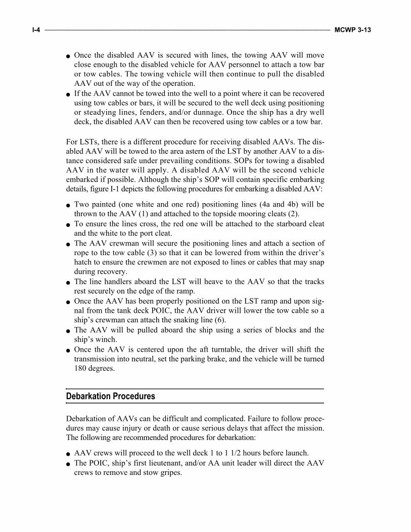
I-4 ______________________________________________________________________________________________________ MCWP 3-13
Once the disabled AAV is secured with lines, the towing AAV will moveclose enough to the disabled vehicle for AAV personnel to attach a tow baror tow cables. The towing vehicle will then continue to pull the disabledAAV out of the way of the operation.
If the AAV cannot be towed into the well to a point where it can be recoveredusing tow cables or bars, it will be secured to the well deck using positioningor steadying lines, fenders, and/or dunnage. Once the ship has a dry welldeck, the disabled AAV can then be recovered using tow cables or a tow bar.
For LSTs, there is a different procedure for receiving disabled AAVs. The dis-abled AAV will be towed to the area astern of the LST by another AAV to a dis-tance considered safe under prevailing conditions. SOPs for towing a disabledAAV in the water will apply. A disabled AAV will be the second vehicleembarked if possible. Although the ship’s SOP will contain specific embarkingdetails, figure I-1 depicts the following procedures for embarking a disabled AAV:
Two painted (one white and one red) positioning lines (4a and 4b) will bethrown to the AAV (1) and attached to the topside mooring cleats (2).
To ensure the lines cross, the red one will be attached to the starboard cleatand the white to the port cleat.
The AAV crewman will secure the positioning lines and attach a section ofrope to the tow cable (3) so that it can be lowered from within the driver’shatch to ensure the crewmen are not exposed to lines or cables that may snapduring recovery.
The line handlers aboard the LST will heave to the AAV so that the tracksrest securely on the edge of the ramp.
Once the AAV has been properly positioned on the LST ramp and upon sig-nal from the tank deck POIC, the AAV driver will lower the tow cable so aship’s crewman can attach the snaking line (6).
The AAV will be pulled aboard the ship using a series of blocks and theship’s winch.
Once the AAV is centered upon the aft turntable, the driver will shift thetransmission into neutral, set the parking brake, and the vehicle will be turned180 degrees.
Debarkation Procedures
Debarkation of AAVs can be difficult and complicated. Failure to follow proce-dures may cause injury or death or cause serious delays that affect the mission.The following are recommended procedures for debarkation:
AAV crews will proceed to the well deck 1 to 1 1/2 hours before launch. The POIC, ship’s first lieutenant, and/or AA unit leader will direct the AAV
crews to remove and stow gripes.

Employment of Amphibious Assault Vehicles ________________________________________________________________ I-5
1
22
4a 4b
6
10
8
1211
9
7
5
3
1. AAV
2. AAV Mooring Cleats
3. Tow Cable
4a. White Positioning Line
4b. Red Positioning Line
5. Portable Bitts
6. Snaking Line
7. Traveling Block
8. Standing Block
9. Fairlead Block
10. Snaking Winch
11. 6 Nylon Line
12. Baxter Bolt
AftTurntable
Well Deck
Figure I-1. LST Recovery Diagram.

I-6 ______________________________________________________________________________________________________ MCWP 3-13
The ship’s personnel must turn on the well-deck blowers or vent fans to highbefore the AAVs are started.
The AAV crews conduct preliminary AAV warmups at least 1 hour beforelaunch. Warmups in groups of not more than three AAVs at one time ensureengine exhaust fumes remain within well-deck blower capacity.
AAV crews will stand by to embark troops after AAVs have been warmedup, checked, and shut down. Vehicles will only be restarted with permissionof the AA unit leader or well-deck debark control.
Troops should embark aboard their respective AAV no later than 30 to 45minutes before launch and after the AAV engines are shut down. To reduceconfusion and prevent injuries, only AAV personnel and necessary ship’screw should move in and among vehicles until time to load troops.
Personnel may be required to load through the rear personnel hatch or throughtopside cargo hatches if tight spacing between AAVs prevents ramps fromopening. The debarkation schedule must allow time for such delays and forinexperienced troops to receive safety briefs and find their way to their vehicle.
The individual vehicle crew chiefs will manifest or verify premade manifestsof all personnel to be embarked in their vehicles.
The AA unit leader will collect, check, and give these manifests to the POIC. AAV crews will properly mark AAVs before debarkation during night oper-ations. During night training launches, only blue or red chemical lights willbe attached to one of each AAV’s antennas. Green will not be used, as it is asignal or marker for a man overboard. If used in combat, chemical lights willbe taped so that only the rear portion is showing to minimize enemy observa-tion from shore.
The ship’s personnel will signal the first wave of AAVs to restart theirengines.
The first AAV will then proceed as directed to the launch line that is locatedapproximately one AAV length from the sill (for LSTs, it is a white line justforward of the stern gate traction bars). The AAV will be stopped by a redflag during the day or red wand at night.
AAVs will be staged in consecutive pairs at the launch line with a minimum3-foot clearance between vehicles, regardless of whether AAVs are launchedin a single column or in pairs. LSTs can only launch AAVs singly in column.
The ship’s personnel will use flags to launch the AAVs, which are normallylaunched singly.
Each succeeding AAV, or pair of AAVs, will launch when the precedingAAV is clear and the ship’s personnel give the signal. The next AAV willautomatically move up to the launch line as each lead AAV launches. Thesignal to launch is a rapid waving of the green flag during the day or rapidwaving of the green wand at night.
AAVs of the follow-on waves will not restart their engines until signaled todo so by the ship’s personnel. Normally, this signal is given 5 minutes beforelaunch of that wave.

APPENDIX J. STANDARD FLAGS, LIGHTS, AND MARKERS USED TO CONTROL AAVS
The illustrations in this appendix include flags, lights, and markers that areemployed at sea and ashore in the control of AAVs. These devices are alsostandard to landing craft and landing ships. Appendix C to MCWP 3-31.5 con-tains more illustrations of control means. The following symbols are used in theillustrations in this appendix:
Steady light =
Blinking light =
PageBeach Markers (from Seaward)
Beach Red One . . . . . . . . . . . . . . . . . . . . . . . . . . . . . . . . . . . . . . . . . . . J-3Beach Red Two . . . . . . . . . . . . . . . . . . . . . . . . . . . . . . . . . . . . . . . . . . . J-3
Oceanographic Markers (from Seaward)Rocks, Shoals, and Obstruction. . . . . . . . . . . . . . . . . . . . . . . . . . . . . . . J-4Port . . . . . . . . . . . . . . . . . . . . . . . . . . . . . . . . . . . . . . . . . . . . . . . . . . . . J-4Starboard . . . . . . . . . . . . . . . . . . . . . . . . . . . . . . . . . . . . . . . . . . . . . . . . J-4Fairway of Channel . . . . . . . . . . . . . . . . . . . . . . . . . . . . . . . . . . . . . . . . J-4
Miscellaneous Beach SignsOne Way . . . . . . . . . . . . . . . . . . . . . . . . . . . . . . . . . . . . . . . . . . . . . . . . J-5Dump Direction Sign. . . . . . . . . . . . . . . . . . . . . . . . . . . . . . . . . . . . . . . J-5Dud Flag . . . . . . . . . . . . . . . . . . . . . . . . . . . . . . . . . . . . . . . . . . . . . . . . J-5Dump Flag . . . . . . . . . . . . . . . . . . . . . . . . . . . . . . . . . . . . . . . . . . . . . . . J-5Medical Evacuation Station. . . . . . . . . . . . . . . . . . . . . . . . . . . . . . . . . . J-5Mine Cleared Area . . . . . . . . . . . . . . . . . . . . . . . . . . . . . . . . . . . . . . . . J-5
Unloading Point MarkersAmmunition. . . . . . . . . . . . . . . . . . . . . . . . . . . . . . . . . . . . . . . . . . . . . . J-6Rations. . . . . . . . . . . . . . . . . . . . . . . . . . . . . . . . . . . . . . . . . . . . . . . . . . J-6Tracked Vehicles . . . . . . . . . . . . . . . . . . . . . . . . . . . . . . . . . . . . . . . . . . J-6Medical Supplies Casualty Evacuation . . . . . . . . . . . . . . . . . . . . . . . . . J-6Wheeled Vehicles . . . . . . . . . . . . . . . . . . . . . . . . . . . . . . . . . . . . . . . . . J-6Oil and Gas . . . . . . . . . . . . . . . . . . . . . . . . . . . . . . . . . . . . . . . . . . . . . . J-6Miscellaneous Supplies . . . . . . . . . . . . . . . . . . . . . . . . . . . . . . . . . . . . . J-7Beaching Point for LST. . . . . . . . . . . . . . . . . . . . . . . . . . . . . . . . . . . . . J-7Causeway Range Markers . . . . . . . . . . . . . . . . . . . . . . . . . . . . . . . . . . . J-7

J-2 _____________________________________________________________________________________________________ MCWP 3-13
Miscellaneous Flags and Identification InsigniaBoat Group Commander . . . . . . . . . . . . . . . . . . . . . . . . . . . . . . . . . . . J-8Assistant Boat Group Commander . . . . . . . . . . . . . . . . . . . . . . . . . . . J-8Channel Control Boat. . . . . . . . . . . . . . . . . . . . . . . . . . . . . . . . . . . . . . J-8AAV Emergency Flag . . . . . . . . . . . . . . . . . . . . . . . . . . . . . . . . . . . . . J-8Amphibious Vehicle Pool Control Officer . . . . . . . . . . . . . . . . . . . . . J-8Transfer Line Control Officer . . . . . . . . . . . . . . . . . . . . . . . . . . . . . . . J-8Self-Propelled Vehicle Embarked . . . . . . . . . . . . . . . . . . . . . . . . . . . . J-9Bulk Cargo Requiring Personnel or Crane to Unload . . . . . . . . . . . . . J-9Cargo Requiring Assistance of Prime Mover to Unload . . . . . . . . . . . J-9Boats Assigned to Floating Dumps . . . . . . . . . . . . . . . . . . . . . . . . . . . J-9Bowser Boat . . . . . . . . . . . . . . . . . . . . . . . . . . . . . . . . . . . . . . . . . . . . . J-9Casualty Receiving Treatment Ship. . . . . . . . . . . . . . . . . . . . . . . . . . . J-9Salvage Boat . . . . . . . . . . . . . . . . . . . . . . . . . . . . . . . . . . . . . . . . . . . . J-9Boat Team Paddle (third boat, second wave) . . . . . . . . . . . . . . . . . . . J-10Serial Paddle for On-Call and Nonscheduled Waves . . . . . . . . . . . . . J-10Beach Red One Flag . . . . . . . . . . . . . . . . . . . . . . . . . . . . . . . . . . . . . . J-10Beach Red Two Flag . . . . . . . . . . . . . . . . . . . . . . . . . . . . . . . . . . . . . . J-10Medical Boat . . . . . . . . . . . . . . . . . . . . . . . . . . . . . . . . . . . . . . . . . . . . J-11Senior Beachmaster . . . . . . . . . . . . . . . . . . . . . . . . . . . . . . . . . . . . . . . J-11

Employment of Amphibious Assault Vehicles _______________________________________________________________ J-3
Beach Markers (From Seaward)
Beach Red One
Beach Red Two
Day
Night
Day
Night

J-4 _____________________________________________________________________________________________________ MCWP 3-13
Oceanographic Markers (From Seaward)
Day
Night
Day
Night
Day
Night
Day
Night
Rocks, Shoals, and Obstruction
Port
Starboard
Fairway of Channel

Employment of Amphibious Assault Vehicles _______________________________________________________________ J-5
Miscellaneous Beach Signs
One
WayAmmo
SP AID
EVA STA
Road
One Way Dump Direction Sign
Dud Flag Dump Flag
MedicalEvacuation Station
Mine Cleared Area

J-6 _____________________________________________________________________________________________________ MCWP 3-13
Unloading Point Markers
Day
Night
Day
Night
Day
Night
Day
Night
Day
Night
Day
Night
Ammunition Rations
Tracked Vehicles Medical SuppliesCasualty Evacuation
Wheeled VehiclesOil and Gas

Employment of Amphibious Assault Vehicles _______________________________________________________________ J-7
Day
Night
Night
Day
Day
Night
Miscellaneous Supplies
Beaching Point for LST
Causeway Range Markers

J-8 _____________________________________________________________________________________________________ MCWP 3-13
Miscellaneous Flags and Identification InsigniaZero
Beach FlagBeach Flag
W
C N
Y T
Boat Group Commander Assistant BoatGroup Commander
Channel Control Boat AAV Emergency Flag
Amphibious VehiclePool Control Officer
Transfer LineControl Officer

Employment of Amphibious Assault Vehicles _______________________________________________________________ J-9
BM
Day
Night
S
Self-PropelledVehicle Embarked
Bulk Cargo RequiringPersonnel or Crane to Unload
Cargo Requiring Assistance of Prime Mover to Unload
Boats Assignedto Floating Dumps
Bowser Boat
Casualty Receiving Treatment Ship
Salvage Boat

J-10 ____________________________________________________________________________________________________ MCWP 3-13
2-32-3 123123
Boat Team Paddle(third boat, second wave)
Serial Paddle for On-Calland Nonscheduled Waves
Beach Red One Flag Beach Red Two Flag

Employment of Amphibious Assault Vehicles ______________________________________________________________ J-11
M
Beach Flag
Day
Night
W
B
Medical Boat
Senior Beachmaster

APPENDIX K. HAND ANDARM SIGNALS FOR CONTROL OF AAVS
The use of hand and arm signals aboard AAVs helps to safely control the move-ment of individual AAVs or AAV units. This appendix presents AAV crews witha uniform, standardized set of signals for conducting day and night operations.AAV crewmen, particularly drivers, should understand the listed hand and armsignals to ensure safe and effective operations during training and combat.
PageAssemble or Pass Towline . . . . . . . . . . . . . . . . . . . . . . . . . . . . . . . . . . . . K-2Attention. . . . . . . . . . . . . . . . . . . . . . . . . . . . . . . . . . . . . . . . . . . . . . . . . . K-2Cease Fire. . . . . . . . . . . . . . . . . . . . . . . . . . . . . . . . . . . . . . . . . . . . . . . . . K-3Close Up. . . . . . . . . . . . . . . . . . . . . . . . . . . . . . . . . . . . . . . . . . . . . . . . . . K-3I Do Not Understand . . . . . . . . . . . . . . . . . . . . . . . . . . . . . . . . . . . . . . . . K-4Column Right (Left). . . . . . . . . . . . . . . . . . . . . . . . . . . . . . . . . . . . . . . . . K-4Commence Firing. . . . . . . . . . . . . . . . . . . . . . . . . . . . . . . . . . . . . . . . . . . K-5Decrease Speed (Vehicles) Quick Time (Dismounted Troops) . . . . . . . . K-5Disperse . . . . . . . . . . . . . . . . . . . . . . . . . . . . . . . . . . . . . . . . . . . . . . . . . . K-6Dismount, Down, Take Cover . . . . . . . . . . . . . . . . . . . . . . . . . . . . . . . . . K-6Echelon Right (Left). . . . . . . . . . . . . . . . . . . . . . . . . . . . . . . . . . . . . . . . . K-7Disregard Previous Command—As You Were . . . . . . . . . . . . . . . . . . . . K-7Form Column . . . . . . . . . . . . . . . . . . . . . . . . . . . . . . . . . . . . . . . . . . . . . . K-8Advance or Move Out . . . . . . . . . . . . . . . . . . . . . . . . . . . . . . . . . . . . . . . K-8Halt, Stop, Stop Towing. . . . . . . . . . . . . . . . . . . . . . . . . . . . . . . . . . . . . . K-9Increase Speed, Doubletime. . . . . . . . . . . . . . . . . . . . . . . . . . . . . . . . . . . K-9Line Formation, Deploy into Line Abreast, as Skirmishers. . . . . . . . . . . K-10Man Overboard . . . . . . . . . . . . . . . . . . . . . . . . . . . . . . . . . . . . . . . . . . . . K-10Mount . . . . . . . . . . . . . . . . . . . . . . . . . . . . . . . . . . . . . . . . . . . . . . . . . . . . K-11Open Up, Extend . . . . . . . . . . . . . . . . . . . . . . . . . . . . . . . . . . . . . . . . . . . K-11By the Right (Left) Flank . . . . . . . . . . . . . . . . . . . . . . . . . . . . . . . . . . . . . K-12Start Engines, Prepare to Move . . . . . . . . . . . . . . . . . . . . . . . . . . . . . . . . K-12Stop Engine, Cut Engine . . . . . . . . . . . . . . . . . . . . . . . . . . . . . . . . . . . . . K-13V Formation . . . . . . . . . . . . . . . . . . . . . . . . . . . . . . . . . . . . . . . . . . . . . . . K-13Wedge Formation. . . . . . . . . . . . . . . . . . . . . . . . . . . . . . . . . . . . . . . . . . . K-14Breakdown . . . . . . . . . . . . . . . . . . . . . . . . . . . . . . . . . . . . . . . . . . . . . . . . K-14Commence Towing . . . . . . . . . . . . . . . . . . . . . . . . . . . . . . . . . . . . . . . . . K-15Cast Off Towline . . . . . . . . . . . . . . . . . . . . . . . . . . . . . . . . . . . . . . . . . . . K-15Air Attack. . . . . . . . . . . . . . . . . . . . . . . . . . . . . . . . . . . . . . . . . . . . . . . . . K-16Nuclear Warning . . . . . . . . . . . . . . . . . . . . . . . . . . . . . . . . . . . . . . . . . . . K-16Ramp Up and Dogged . . . . . . . . . . . . . . . . . . . . . . . . . . . . . . . . . . . . . . . K-17Ramp Down . . . . . . . . . . . . . . . . . . . . . . . . . . . . . . . . . . . . . . . . . . . . . . . K-17Vector Left (Right). . . . . . . . . . . . . . . . . . . . . . . . . . . . . . . . . . . . . . . . . . K-17Pivot Right . . . . . . . . . . . . . . . . . . . . . . . . . . . . . . . . . . . . . . . . . . . . . . . . K-18Pivot Left . . . . . . . . . . . . . . . . . . . . . . . . . . . . . . . . . . . . . . . . . . . . . . . . . K-18Right Turn . . . . . . . . . . . . . . . . . . . . . . . . . . . . . . . . . . . . . . . . . . . . . . . . K-19Left Turn . . . . . . . . . . . . . . . . . . . . . . . . . . . . . . . . . . . . . . . . . . . . . . . . . K-19Move Forward . . . . . . . . . . . . . . . . . . . . . . . . . . . . . . . . . . . . . . . . . . . . . K-20Move in Reverse. . . . . . . . . . . . . . . . . . . . . . . . . . . . . . . . . . . . . . . . . . . . K-20Vehicle Halt . . . . . . . . . . . . . . . . . . . . . . . . . . . . . . . . . . . . . . . . . . . . . . . K-21

K-2 _____________________________________________________________________________________________________ MCWP 3-13
Assemble or Pass TowlineDay Night
Small circle, palm out.Turn light on when right arm is extended overhead; execute large horizontal circle. Turn light off before lowering arm. Repeat as necessary.
Attention
Turn light on when arm is in the starting position. Turn light off when signal is completed. Repeat as necessary.
1.
2.
3.

Employment of Amphibious Assault Vehicles ________________________________________________________________ K-3
Cease FireDay Night
Turn light on when arm is in the starting position. Turn light off when signal is completed. Repeat as necessary.
Close Up
Turn light on when arms are in the starting position; execute signal, turning light off when hands touch overhead. Repeat as necessary.
2.
3.
1.
1.
2.

K-4 _____________________________________________________________________________________________________ MCWP 3-13
I Do Not UnderstandDay Night
Turn lights on as hands are brought down across the face; hold in position, parallel, horizontal, until acknowledged. Turn lights off while they are still in front of the face.
Column Right (Left)
Turn light on as arm is extended; hold in position until understood or acknowledged or the maneuver is executed. Turn light off while arm is still extended. Repeat as necessary.

Employment of Amphibious Assault Vehicles ________________________________________________________________ K-5
Commence FiringDay Night
Turn light on when arm is in the starting position. Turn light off when signal is completed. Repeat as necessary.
Decrease Speed (Vehicles)Quick Time (Dismounted Troops)
Turn light on when arm is in the starting position. Turn light off when signal is completed. Arm does not move above the horizontal position. Repeat as necessary.
2.
1.
2.
1.

K-6 _____________________________________________________________________________________________________ MCWP 3-13
DisperseDay Night
Turn light on when arm is in starting position. Return arm to starting position after each movement in a given direction. Turn light off after arm has been moved to the rear.
Dismount, Down, Take Cover
Turn light on when arm is in the starting position. Turn light off when arm is down at the side. Repeat as necessary.
5.
4.
3.
2.
1.
2.
1.

Employment of Amphibious Assault Vehicles ________________________________________________________________ K-7
Echelon Right (Left)Day Night
Turn lights on when arms are in correct positions. Turn lights off before taking arms from the signal position. Repeat as necessary.
Disregard Previous Command—As You Were
Wands are crossed instead of the hands. Turn lights on when wands are in position overhead. Turn lights off when signal is understood or acknowledged.

K-8 _____________________________________________________________________________________________________ MCWP 3-13
Form ColumnDay Night
Turn light on when arm movement for signal is started. Turn light off when completed. Repeat as necessary.
Advance or Move Out
Face the desired direction of movement; turn light on when arm is extended to the rear; swing arm overhead and forward in the direction of desired movement. Turn light off when arm is in horizontal position. Repeat as necessary.
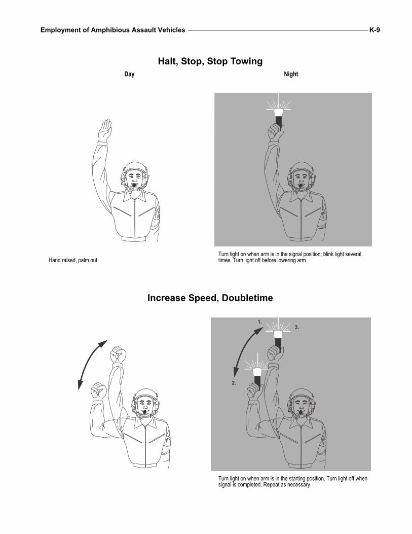
Employment of Amphibious Assault Vehicles ________________________________________________________________ K-9
Halt, Stop, Stop TowingDay Night
Hand raised, palm out.Turn light on when arm is in the signal position; blink light several times. Turn light off before lowering arm.
Increase Speed, Doubletime
Turn light on when arm is in the starting position. Turn light off when signal is completed. Repeat as necessary.
2.
1.
3.

K-10 ____________________________________________________________________________________________________ MCWP 3-13
Line Formation, Deploy into Line Abreast, as SkirmishersDay Night
Turn lights on as arms are extended; hold in position until signal is understood or acknowledged or the maneuver is executed. Turn lights off while arms are still in signal position. Repeat as necessary.
Man Overboard
Turn light on when arm is in vertical position; execute complete circle while blinking the light. Turn light off when arm is returned to the vertical position. Repeat as necessary.
1. 2.

Employment of Amphibious Assault Vehicles ______________________________________________________________ K-11
MountDay Night
Turn light on in starting position. Turn light off when arm is 45 degrees above horizontal position. Repeat as necessary.
Open Up, Extend
Turn lights on when arms are in starting position. Turn lights off when arms are in horizontal position. Repeat as necessary.
1.
2.
1.
2.

K-12 ____________________________________________________________________________________________________ MCWP 3-13
By the Right (Left) FlankDay Night
Extend the right (left) arm parallel to the deck and hold the left (right) arm above the head so that both arms are at a 90-degree angle to each other. At the point of execution, move the left (right) arm across the body as if to clap hands together.
Start Engines, Prepare to Move
Turn light on when arm is in starting position. Turn light off when signal is completed.

Employment of Amphibious Assault Vehicles ______________________________________________________________ K-13
Stop Engine, Cut EngineDay Night
CAUTION: This signal should not be used for waterborne AAVs. Turn light on when arm is in starting position. Turn light off when signal is completed.
V Formation
Turn lights on as arms are extended; hold in position until signal is understood or acknowledged or the maneuver is executed. Turn lights off while arms are still in signal positions. Repeat as necessary.
1.
3.2.

K-14 ____________________________________________________________________________________________________ MCWP 3-13
Wedge FormationDay Night
Turn lights on as arms are extended; hold in position until signal is understood or acknowledged or the maneuver is executed.. Turn lights off while arms are still in signal position. Repeat as necessary.
Breakdown
Turn lights on with arms extended overhead. Swing arms forward and down to knees. Swing arms forward and upward from knees to overhead. Continue motion until signal is understood.
1.
2.
3.
1.
2.
3.

Employment of Amphibious Assault Vehicles ______________________________________________________________ K-15
Commence TowingDay Night
Turn light on when arm is in the extended starting position. Move arm in semicircle from right horizontal position downward to left horizontal position. Turn off light when signal is complete. Repeat as necessary.
Cast Off Towline
Turn on lights. Cross arms in front of body several times, using swing motion with wand in each hand.

K-16 ____________________________________________________________________________________________________ MCWP 3-13
Air AttackDay Night
Turn on lights. Rapidly cross and uncross arms fully extended above the head with wand in each hand.
Nuclear Warning
Turn on light. Cover both eyes with wand held in right hand to warn exposed troops to take cover before the detonation of nuclear weapon.

Employment of Amphibious Assault Vehicles ______________________________________________________________ K-17
Ramp Up and DoggedDay Night
Arms held out parallel to deck with hands held open and pointed up. (Coxswains acknowledge with same signal to inform traffic controlman that the ramp is up and dogged.)
Turn on lights. Arms held out parallel to deck with wands pointed straight up. (Coxswains acknowledge with same signal to inform traffic controlman ramp is up and dogged.)
Ramp Down
Arms held out parallel to deck with hands held open and pointed down. (Coxswains acknowledge with same signal.)
Turn on lights. Arms held out parallel to deck with wands pointed straight down. (Coxswains acknowledge with same signal.)
Vector Left (Right)
Signalman faces beach with one arm straight out to side pointing in direction of the turn, other arm raised straight up, palm forward.
Turn on lights. Light wand in each hand; one straight out to side pointing in direction of the turn, other straight up.

K-18 ____________________________________________________________________________________________________ MCWP 3-13
Pivot RightDay Night
Hold one hand, fingers together, palm facing inboard in front of the chest in vertical position. Hold other hand with fingers joined, palm facing down, in horizontal position against vertical hand, in direction vehicle is to travel.
Same as day, except with use of light wands.
Pivot Left
One hand is in front of chest in a vertical position, fingers joined, palm facing perpendicular to the chest. Hold other hand withfingers joined, palm facing down, in horizontal position against vertical hand, in direction vehicle is to travel.
Same as day, except with use of light wands.

Employment of Amphibious Assault Vehicles ______________________________________________________________ K-19
Right TurnDay Night
Form clenched fist on arm in direction of turn is to be made; make beckoning motion with other arm to bring vehicle forward; for reverse, make a pushing motion.
Same as day except point light wand in the direction of the turn.
Left Turn
Form clenched fist on arm in direction of turn is to be made; make beckoning motion with other arm to bring vehicle forward; for reverse, make a pushing motion.
Same as day except point light wand in the direction of the turn.
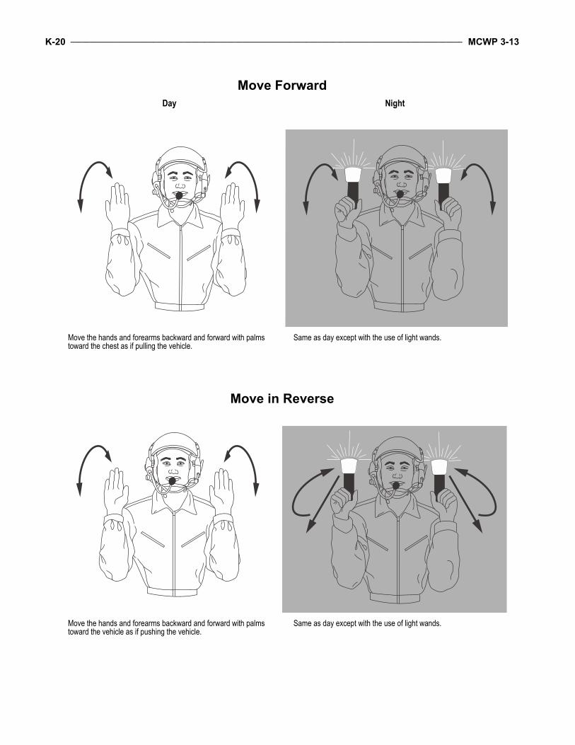
K-20 ____________________________________________________________________________________________________ MCWP 3-13
Move ForwardDay Night
Move the hands and forearms backward and forward with palms toward the chest as if pulling the vehicle.
Same as day except with the use of light wands.
Move in Reverse
Move the hands and forearms backward and forward with palms toward the vehicle as if pushing the vehicle.
Same as day except with the use of light wands.

Employment of Amphibious Assault Vehicles ______________________________________________________________ K-21
Vehicle HaltDay Night
Clasp hands together, palms facing each other at throat level. Cross light wands in front of throat.
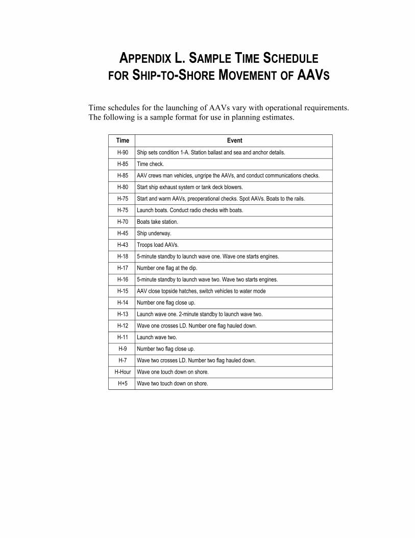
APPENDIX L. SAMPLE TIME SCHEDULE FOR SHIP-TO-SHORE MOVEMENT OF AAVS
Time schedules for the launching of AAVs vary with operational requirements.The following is a sample format for use in planning estimates.
Time EventH-90 Ship sets condition 1-A. Station ballast and sea and anchor details.
H-85 Time check.
H-85 AAV crews man vehicles, ungripe the AAVs, and conduct communications checks.
H-80 Start ship exhaust system or tank deck blowers.
H-75 Start and warm AAVs, preoperational checks. Spot AAVs. Boats to the rails.
H-75 Launch boats. Conduct radio checks with boats.
H-70 Boats take station.
H-45 Ship underway.
H-43 Troops load AAVs.
H-18 5-minute standby to launch wave one. Wave one starts engines.
H-17 Number one flag at the dip.
H-16 5-minute standby to launch wave two. Wave two starts engines.
H-15 AAV close topside hatches, switch vehicles to water mode
H-14 Number one flag close up.
H-13 Launch wave one. 2-minute standby to launch wave two.
H-12 Wave one crosses LD. Number one flag hauled down.
H-11 Launch wave two.
H-9 Number two flag close up.
H-7 Wave two crosses LD. Number two flag hauled down.
H-Hour Wave one touch down on shore.
H+5 Wave two touch down on shore.

APPENDIX M. AMPHIBIOUS SHIP LAUNCH TRACKSThe approach a ship uses when conducting underway launches will affect thelaunch and landing of the AAV unit. The most common types of underway launchtracks that the Navy employs are parallel, turn away, angled, parallel U-turn, andangled U-turn.
Parallel
In a parallel launch track, the ship approaches the beach at 30 to 45 degrees, turnseither left or right parallel to the shore (90 degrees) on or near the LD, launches thewaves in column, and turns quickly out to sea. The AAVs continue in a columnuntil they are inside the boat lane where they flank and begin to move toward thebeach. This is a popular launching technique because the ship is exposed broadsideto the shore for only a short time, the AAV unit is dropped off on or near the LD,and the swim time is short. A disadvantage of using this method is the extra traveltime required for the second wave to make it to the boat lane. See figure M-1.
Ship'sTrack
First Wave AAVs
Boat Lane
Second Wave AAVs
LD
Shore
Figure M-1. Parallel Launch of the First and Second Waves.

M-2 _____________________________________________________________________________________________________ MCWP 3-13
Turn Away
In a turn-away launch track, the ship approaches the beach at approximately0 degrees, conducts a U-turn at the LD, and launches AAVs in a columnheaded directly towards the beach. See figure M-2. This pattern minimizes theship’s exposure to the shoreline and launches the wave in column. Althoughhighly effective at disembarking a wave in column toward the beach, thismaneuver may result in a long approach for the last vehicle launched.
Figure M-2. Turn-Away Launch.
Ship'sTrack
FirstWaveAAVs
Boat Lane
LD
Shore

Employment of Amphibious Assault Vehicles ______________________________________________________________ M-3
Angled
In the angled launch pattern, the ship approaches the shore at a 45-degreeangle and begins to launch AAVs even with the edge of the boat lane.When waterborne, AAVs turn toward the shore and approach the LD. Seefigure M-3.
Figure M-3. Angled Launch of the First Wave.
First Wave AAVs
Boat Lane
LD
Shore
Ship's Track

M-4 _____________________________________________________________________________________________________ MCWP 3-13
As the ship launches the vehicles closer to the LD, the vehicles form on lineand cross the LD. The ship can then turn away and begin a similar approach onthe same boat lane for the second wave. See figure M-4. Vehicles turn immedi-ately toward the shore and begin to assault. This launch track minimizes statictime spent maneuvering in the water.
First Wave AAVs
Boat Lane
LD
Shore
Ship's Track
Second Wave AAVs
Figure M-4. Angled Launch of the Second Wave.

Employment of Amphibious Assault Vehicles ______________________________________________________________ M-5
Parallel U-Turn
The parallel U-turn maneuver combines the parallel launch with the basic turn-away launch. The ship approaches the shore parallel and launches AAVs at theedge of the boat lane. Then the ship conducts a U-turn away from the shore,begins launching the second wave at the opposite edge of the boat lane, andcompletes the maneuver by turning away from the shore. See figure M-5. Thismaneuver exposes the ship to the shoreline for the longest period.
Boat Lane
LD
Shore
Ship's Track
First Wave AAVs
Second Wave AAVs
Figure M-5. Parallel U-Turn Launch.

M-6 _____________________________________________________________________________________________________ MCWP 3-13
Angled U-Turn
The angled U-turn maneuver combines the turn-away and the angled approachpaths. The ship initially conducts an angled launch, executes a tight U-turn, andconducts a parallel launch of the second wave. This maneuver exposes the shipto the shoreline for a slightly shorter period than the parallel U-turn launchtrack. See figure M-6.
Boat Lane
LD
Shore
Ship's Track
First Wave AAVs
Second Wave AAVs
Figure M-6. Angled U-Turn Launch of the First and Second Waves.

APPENDIX N. GLOSSARY
Section I. Acronyms
AA. . . . . . . . . . . . . . . . . .assault amphibian [unit]AAV . . . . . . . . . . . . . amphibious assault vehicleADDRAC . . . . . . . . . alert, direction, description,
range, assignment, controlADCON . . . . . . . . . . . . . . administrative controlAF . . . . . . . . . . . . . . . . . . . . . . . amphibious forceAO. . . . . . . . . . . . . . . . . . . . . . .area of operationsAOA.. . . . . . . . . . . . . . amphibious objective areaAP . . . . . . . . . . . . . . . . . . . . . . . . . attack positionAPC. . . . . . . . . . . . . . . armored personnel carrierAT . . . . . . . . . . . . . . . . . . . . . . . . . . . . . . .antitankATF. . . . . . . . . . . . . . . . . . amphibious task forceATGM. . . . . . . . . . . . . . antitank guided munition
BAS. . . . . . . . . . . . . . . . . . . . battalion aid stationBDAR . . . . . . . . . . . . . battle damage assessment
and repairBGC . . . . . . . . . . . . . . . . boat group commanderBHL . . . . . . . . . . . . . . . . . . . battle handover lineBLT. . . . . . . . . . . . . . . . . . battalion landing teamBP . . . . . . . . . . . . . . . . . . . . . . . . . .battle position
C2 . . . . . . . . . . . . . . . . . . . .command and controlCAS. . . . . . . . . . . . . . . . . . . . . . . close air supportCATF . . . . . . . . . . . . . . commander, amphibious
task forceCCO . . . . . . . . . . . . . . . . . .central control officerCE . . . . . . . . . . . . . . . . . . . . . . . combat equippedCIC . . . . . . . . . . . . . . . combat information centerCL . . . . . . . . . . . . . . . . . . . . . . . . . . . combat loadCLF . . . . . . . . . . . . . . . commander, landing forceCOC . . . . . . . . . . . . . . . combat operations centerCP . . . . . . . . . . . . . . . . . . . . . . . . . command postCSS . . . . . . . . . . . . . . . . . combat service supportCSSA . . . . . . . . . . . .combat service support areaCSSD . . . . . . . . . . . . . . . combat service support
detachmentCSSE. . . . . . . . . .combat service support elementCVC . . . . . . . . . . . . . combat vehicle commander
DAP . . . . . . . . . . . . . .decontamination apparatusD-day . . . . . . . . . . . . . . . unnamed day on which
operations commence orare scheduled to commence
DF . . . . . . . . . . . . . . . . . . . . . . . . . . . . . diesel fuel
DP . . . . . . . . . . . . . . . . . . . . . . . . . dismount pointDPICM . . . . . . . . . . . . . . .dual purpose improved
conventional munitionsDS . . . . . . . . . . . . . . . . . . . . . . . . . . direct supportDS2 . . . . . . . . . . . . . . . . . . decontamination agent
EA . . . . . . . . . . . . . . . . . . . . . . . .engagement areaEAAK . . . . . . . . . . . enhanced appliqué armor kitEMP . . . . . . . . . . . . . . . . . .electromagnetic pulse
FAC. . . . . . . . . . . . . . . . . . . forward air controllerFEBA . . . . . . . . . .forward edge of the battle areaFHA . . . . . . . . . . foreign humanitarian assistanceFM. . . . . . . . . . . . . . . . . . . . field manual (Army)FO . . . . . . . . . . . . . . . . . . . . . . . forward observerFPL . . . . . . . . . . . . . . . . . . . . final protective lineFSC . . . . . . . . . . . . . . . . . fire support coordinatorFSCC. . . . . . . . . . fire support coordination centerFSSG. . . . . . . . . . . . . force service support group
GCE . . . . . . . . . . . . . . . . ground combat elementGPS . . . . . . . . . . . . . . . global positioning systemGS . . . . . . . . . . . . . . . . . . . . . . . . .general support
H&S . . . . . . . . . . . . . . . headquarters and serviceHB. . . . . . . . . . . . . . . . . . . . . . . . . heavy barreledHE . . . . . . . . . . . . . . . . . . . . . . . . . high explosiveHEDP . . . . . . . . . . . .high explosive dual purposeHF . . . . . . . . . . . . . . . . . . . . . . . . . high frequencyH-hour. . . . . . . . . . . . . specific time an operation
or exercise beginsHMMWV . . . . . . . . . high mobility multipurpose
wheeled vehicleHTH . . . . . . . . . . . . . . . . . .high test hypochlorite
IFV . . . . . . . . . . . . . . . . .infantry fighting vehicleIPB . . . . . . . . . . . . . . . intelligence preparation of
the battlespaceIR . . . . . . . . . . . . . . . . . . . . . . . . . . . . . . . infrared
JP. . . . . . . . . . . . . . . . . . . . . . . . . joint publication
LAAD . . . . . . . . . . . . . . . low altitude air defenseLAR . . . . . . . . . . . .light armored reconnaissanceLARC . . . . . . . . . . .lighter, amphibious resupply,
cargoLAV . . . . . . . . . . . . . . . . . . light armored vehicle

N-2 _____________________________________________________________________________________________________ MCWP 3-13
LCAC . . . . . . . . . . . . . . .landing craft air cushionLCM . . . . . . . . . . . . . . landing craft, mechanizedLCU . . . . . . . . . . . . . . . . . . . landing craft, utilityLCVP . . . . . . . . landing craft, vehicle, personnelLD . . . . . . . . . . . . . . . . . . . . . . . . line of departureLDS. . . . . . . lightweight decontamination systemLF . . . . . . . . . . . . . . . . . . . . . . . . . . landing forceLFSP . . . . . . . . . . . . . landing force support partyLHA . . . . . . . . . . . . general purpose amphibious
assault shipLHD . . . . . . . . . . . . . . . . landing helicopter dockLMC . . . . . . . . . . . . . . . . . . . linear mine clearingLOA . . . . . . . . . . . . . . . . . . . . . . limit of advanceLOC . . . . . . . . . . . . . . . lines of communicationsLPD. . . . . . . . . . . . . . . . . . landing platform dockLSD. . . . . . . . . . . . . . . . . . . . . . landing ship dockLST . . . . . . . . . . . . . . . . . . . . . . landing ship, tankLZ . . . . . . . . . . . . . . . . . . . . . . . . . . . landing zone
MAGTF . . . . . . . . . Marine air-ground task forceMBA . . . . . . . . . . . . . . . . . . . . . . main battle areaMCDP . . . . . . Marine Corps doctrinal publicationM/CM . . . . . . . . . . . . . mobility, countermobility MCRP . . . . . .Marine Corps reference publicationMCT . . . . . . . . . . . . . . maintenance contact teamMCWP . . . . . . . . . . . . Marine Corps warfighting
publicationmech . . . . . . . . . . . . . . . . . . . . . . . . . mechanizedMEF . . . . . . . . . . . . . Marine expeditionary forceMETT-T . . . . . . . . . . . . . mission, enemy, terrain
and weather, troops andsupport available—
time availableMEU . . . . . . . . . . . . . . Marine expeditionary unitMEU(SOC) . . . . . . . . . Marine expeditionary unit
(special operations capable)MOOTW. . . . . military operations other than warMOPP . . . . . .mission-oriented protective postureMOS . . . . . . . . . . military occupational specialtyMOUT. . . . . . . . . . . . . . . . military operations on
urbanized terrainMRF . . . . . . . . . . . . . . . . . . mobile riverine forceMSR . . . . . . . . . . . . . . . . . . . . .main supply routeMST . . . . . . . . . . . . . . maintenance support teamMTF . . . . . . . . . . . . . . . . . mechanized task force
N-2 . . . . . . . . . . . . Navy component intelligencestaff officer
N-3 . . . . . . . . . . . . . Navy component operationsstaff officer
NAVSEA . . . . . . . . . . . . . . . . . . . . . . . .naval sea
NBC . . . . . . . . .nuclear, biological, and chemicalNCG . . . . . . . . . . . . . . . . . . . naval control groupNCO . . . . . . . . . . . . . . .noncommissioned officerNEO . . . . . . .noncombatant evacuation operationNGF . . . . . . . . . . . . . . . . . . . . . . . . naval gunfireNWP . . . . . . . . . . . . . . .naval warfare publication
OEM . . . . . . . . . . . . . . . . . on-equipment materialOP . . . . . . . . . . . . . . . . . . . . . . . . observation postOPCON. . . . . . . . . . . . . . . . . . operational controlOPORD. . . . . . . . . . . . . . . . . . . . . operation orderOTH . . . . . . . . . . . . . . . . . . . . . . over the horizon
PCO. . . . . . . . . . . . . . . . . .primary control officerPCS . . . . . . . . . . . . . . . . . . . .primary control shipPDF . . . . . . . . . . . . . . . . principal direction of firePLD. . . . . . . . . . . . . probable line of deploymentPLGRS . . . . . . . . . . . . . . . . precision lightweight
global positioning system (GPS)receiver system
PLRS. . . . . . . . position location reporting systemPM. . . . . . . . . . . . . . . . . . preventive maintenanceP/N . . . . . . . . . . . . . . . . . . . . . . . . . . part numberPOIC . . . . . . . . . . . . . . . . . petty officer in chargePOL. . . . . . . . . . . . petroleum, oils, and lubricantsPOW . . . . . . . . . . . . . . . . . . . . . . . prisoner of war
QLP. . . . . . . . . . . . . . . . . quiet landing procedure
R-day. . . . . . . . . . . . . . . . . . . . .redeployment dayRAM/RS . . . . . . . . . . reliability, availability, and
maintainability/rebuildto standard
rein . . . . . . . . . . . . . . . . . . . . . . . . . . . reinforcingRHA . . . . . . . . . . . . . . rolled homogenous armorRLT. . . . . . . . . . . . . . . . .regimental landing teamRP . . . . . . . . . . . . . . . . . . . . . . . . . . . release pointRPM . . . . . . . . . . . . . . . . . revolutions per minuteR&S . . . . . . . . . reconnaissance and surveillanceRT . . . . . . . . . . . . . . . . . . . . . . . . . . . .rescue team
S-1. . . . . . . . . . . . . . . . . . .manpower staff officerS-2. . . . . . . . . . . . . . . . . . intelligence staff officerS-3. . . . . . . . . . . . . . . . . . . operations staff officerS-4. . . . . . . . . . . . . . . . . . . . logistics staff officerS-6. . . . . . . . . . communications and information
systems officer (units andorganizations below the
major subordinatecommand level)
SCS . . . . . . . . . . . . . . . . . . secondary control shipSDS . . . . . . . . . . sorbent decontamination system

Employment of Amphibious Assault Vehicles ________________________________________________________________ N-3
SFP . . . . . . . . . . . . . . . . . support by fire positionSINCGARS. . . . . . . . . single-channel ground and
airborne radio systemSLAP. . . . . . . . . . . . . sabot light armor penetratorSOC. . . . . . . . . . . . . . . special operations capableSOP . . . . . . . . . . . . . standing operating procedureSP . . . . . . . . . . . . . . . . . . . . . . . . . . . . . start pointSTB . . . . . . . . . . . . . . . . . . . super tropical bleachSUROB . . . . . . . . . . . . . . . surf observation report
TACON. . . . . . . . . . . . . . . . . . . . . tactical controlTC . . . . . . . . . . . . . . . . . . . . . . . troop commanderT/E . . . . . . . . . . . . . . . . . . . . . table of equipmentTI. . . . . . . . . . . . . . . . . . . . . . technical instruction
TL . . . . . . . . . . . . . . . . . . . . . . . . . . . . . troop loadTLOC . . . . . . . tactical logistics operations centerTM . . . . . . . . . . . . . . . . . . . . . . . . . Marine Corps
technical manualTOW . . . . . . . . . tube-launched, optically-tracked,
wire-command link guided missileTRP . . . . . . . . . . . . . . . . . . . target reference point
UGWS. . . . . . . . . . . . up-gunned weapons stationUHF . . . . . . . . . . . . . . . . . . . ultrahigh frequencyUS . . . . . . . . . . . . . . . . . . . . . . . . . . United States
VHF . . . . . . . . . . . . . . . . . . . very high frequency
WGO. . . . . . . . . . . . . . . . . . . . wave guide officer

N-4 _____________________________________________________________________________________________________ MCWP 3-13
Section II. Definitions
amphibious force—An amphibious task forceand a landing force together with other forces thatare trained, organized, and equipped for amphibi-ous operations. Also called AF. (JP 1-02)
amphibious operation—A military operationlaunched from the sea by an amphibious force,embarked in ships or craft with the primarypurpose of introducing a landing force ashore toaccomplish the assigned mission. (JP 1-02)
amphibious task force—A Navy task organiza-tion formed to conduct amphibious operations.The amphibious task force, together with thelanding force and other forces, constitutes theamphibious force. Also called ATF. (JP 1-02)
amphibious vehicle availability table—A tabu-lation of the type and number of amphibiousvehicles available primarily for assault landingsand for support of other elements of the opera-tion. (JP 1-02)
amphibious vehicle employment plan—A planshowing in tabular form the planned employ-ment of amphibious vehicles in landing opera-tions, including their employment after the initialmovement to the beach. (JP 1-02)
approach lane—An extension of a boat lanefrom the line of departure toward the transportarea. (JP 1-02)
approach march—Advance of a combat unitwhen direct contact with the enemy is imminent.Troops are fully or partially deployed. Theapproach march ends when ground contact withthe enemy is made or when the attack position isoccupied. (JP 1-02)
armored personnel carrier—A lightly armored,highly mobile, full-tracked vehicle, amphibiousand air-droppable, used primarily for transport-ing personnel and their individual equipmentduring tactical operations. Production modifica-
tions or application of special kits permit use as amortar carrier, command post, flame thrower,antiaircraft artillery chassis, or limited recoveryvehicle. Also called APC. (JP 1-02)
assault schedule—See landing schedule.(JP 1-02)
assault wave—See wave. (JP 1-02)
backshore—The area of a beach extending fromthe limit of high water foam lines to dunes orextreme inland limit of the beach. (JP 1-02)
base of fire—Fire placed on an enemy force orposition to reduce or eliminate the enemy’s capa-bility to interfere by fire and/or movement withfriendly maneuver element(s). It may be providedby a single weapon or a grouping of weaponssystems. (MCRP 5-12C)
battle damage repair—Essential repair, whichmay be improvised, carried out rapidly in a battleenvironment in order to return damaged ordisabled equipment to temporary service.(JP 1-02)
beaten zone—The area on the ground uponwhich the cone of fire falls. (JP 1-02)
boat group—The basic organization of landingcraft. One boat group is organized for each battal-ion landing team (or equivalent) to be landed inthe first trip of landing craft or amphibious vehi-cles. (JP 1-02)
boat lane—A lane for amphibious assault land-ing craft, which extends seaward from the land-ing beaches to the line of departure. The width ofa boat lane is determined by the length of thecorresponding beach. (JP 1-02)
central control officer—The officer designatedby the amphibious task force commander for theoverall coordination of the waterborne ship-
Employment of Amphibious Assault Vehicles ________________________________________________________________ N-5
to-shore movement. The central control officer isembarked in the central control ship. Also calledCCO. (JP 1-02)
centralized control—In military operations, amode of battlespace management in which oneechelon of command exercises total authority anddirection of all aspects of one or more warfight-ing functions. It is a method of control wheredetailed orders are issued and total unity of actionis the overriding consideration. See also decen-tralized control. (MCRP 5-12C)
close air support—Air action by fixed- androtary-wing aircraft against hostile targets that arein close proximity to friendly forces and thatrequire detailed integration of each air missionwith the fire and movement of those forces. Alsocalled CAS. (JP 1-02)
combat air patrol—An aircraft patrol providedover an objective area, the force protected, thecritical area of a combat zone, or in an air defensearea, for the purpose of intercepting and destroy-ing hostile aircraft before they reach their targets.(JP 1-02)
counterattack—Attack by part or all of adefending force against an enemy attacking force,for such specific purposes as regaining groundlost or cutting off or destroying enemy advanceunits, and with the general objective of denyingto the enemy the attainment of the enemy'spurpose in attacking. In sustained defensive oper-ations, it is undertaken to restore the battle posi-t ion and is directed at l imited objectives.(JP 1-02)
covering force—1. A force operating apart fromthe main force for the purpose of intercepting,engaging, delaying, disorganizing, and deceivingthe enemy before the enemy can attack the forcecovered. 2. Any body or detachment of troopswhich provides security for a larger force byobservation, reconnaissance, attack, or defense,
or by any combinat ion of these methods.(JP 1-02)
cross-attachment—The exchange of subordi-nate units between units for a temporary period.(MCRP 5-12C)
current, offshore—Deep water movementscaused by tides or seasonal changes in oceanwater level. (JP 1-02)
decentralized control—In military operations, amode of battlespace management in which acommand echelon may delegate some or allauthority and direction for warfighting functionsto subordinates. It requires careful and clear artic-ulation of mission, intent, and main effort tounify efforts of subordinate leaders. See alsocentralized control. (MCRP 5-12C)
demonstration—1. An attack or show of forceon a front where a decision is not sought, madewith the aim of deceiving the enemy. 2. (DODonly) In military deception, a show of force in anarea where a decision is not sought made todeceive an adversary. It is similar to a feint butno actual contact with the adversary is intended.(JP 1-02)
electromagnetic pulse—The electromagneticradiation from a strong electronic pulse, mostcommonly caused by a nuclear explosion thatmay couple with electrical or electronic systemsto produce damaging current and voltage surges.Also called EMP. (JP 1-02)
envelopment—An offensive maneuver in whichthe main attacking force passes around or overthe enemy's principal defensive positions tosecure objectives to the enemy's rear. See alsoturning movement. (JP 1-02)
exploitation—1. Taking full advantage of successin military operations, following up initial gains,and making permanent the temporary effects

N-6 _____________________________________________________________________________________________________ MCWP 3-13
already achieved. 2. Taking full advantage of anyinformation that has come to hand for tactical,operational, or strategic purposes. 3. An offensiveoperation that usually follows a successful attackand is designed to disorganize the enemy in depth.See also pursuit. (JP 1-02)
feint—In military deception, an offensive actioninvolving contact with the adversary conductedfor the purpose of deceiving the adversary as tothe location and/or time of the actual main offen-sive action. (JP 1-02)
flanking attack—An offensive maneuverdirected at the flank of an enemy. See also fron-tal attack. (JP 1-02)
foreshore—That portion of a beach extendingfrom the low water (datum) shoreline to the limitof normal high water wave wash. (JP 1-02)
forward arming and refueling point—Atemporary facility—organized, equipped, anddeployed by an aviat ion commander, andnormally located in the main battle area closer tothe area where operations are being conductedthan the aviation unit's combat service area—toprovide fuel and ammunition necessary for theemployment of aviation maneuver units incombat. The forward arming and refueling pointpermits combat aircraft to rapidly refuel andrearm simultaneously. (JP 1-02)
forward edge of the battle area—The foremostlimits of a series of areas in which ground combatunits are deployed, excluding the areas in whichthe covering or screening forces are operating,designated to coordinate fire support, the posi-tioning of forces, or the maneuver of units. Alsocalled FEBA. (JP 1-02)
frontal attack—1. An offensive maneuver inwhich the main action is directed against the frontof the enemy forces. 2. In air intercept, an attackby an interceptor aircraft that terminates with a
heading crossing angle greater than 135 degrees.(JP 1-02)
global positioning system—A satellite constella-tion that provides highly accurate position, veloc-ity, and time navigation information to users.Also called GPS. (JP 1-02)
guard—1. A form of security operation whoseprimary task is to protect the main force by fight-ing to gain time while also observing and report-ing information, and to prevent enemy groundobservation of and direct fire against the mainbody by reconnoitering, attacking, defending, anddelaying. A guard force normally operates withinthe range of the main body's indirect fire weap-ons. 2. A radio frequency that is normally usedfor emergency transmissions and is continuouslymonitored. UHF band: 243.0 MHZ; VHF band:121.5 MHZ. See also screen. 3. A military orcivilian individual assigned to protect personnel,equipment, or installations, or to oversee a pris-oner. (JP 1-02)
hinterland, near—The area of land within anoperational area of a specific beach or terminaloperation—usually within 5 miles. (JP 1-02)
hydrography—The science which deals with themeasurements and description of the physicalfeatures of the oceans, seas, lakes, rivers, andtheir adjoining coastal areas, with particularreference to their use for navigational purposes.(JP 1-02)
infiltration—1. The movement through or intoan area or territory occupied by either friendly orenemy troops or organizations. The movement ismade, either by small groups or by individuals, atextended or irregular intervals. When used inconnection with the enemy, it infers that contactis avoided. 2. In intelligence usage, placing anagent or other person in a target area in hostileterritory. Usually involves crossing a frontier orother guarded line. Methods of infiltration are:

Employment of Amphibious Assault Vehicles ________________________________________________________________ N-7
black (clandestine); grey (through legal crossingpoint but under false documentation); and white(legal). (JP 1-02)
inner transport area—In amphibious opera-tions, an area as close to the landing beach asdepth of water, navigational hazards, boat traffic,and enemy action permit, to which transportsmay move to expedite unloading. (JP 1-02)
landing beach—That portion of a shorelineusually required for the landing of a battalionlanding team. However, it may also be thatportion of a shoreline constituting a tactical local-ity (such as the shore of a bay) over which a forcelarger or smaller than a battalion landing teammay be landed. (JP 1-02)
landing craft and amphibious vehicle assign-ment table—A table showing the assignment ofpersonnel and materiel to each landing craft andamphibious vehicle and the assignment of thelanding craft and amphibious vehicles to wavesfor the ship-to-shore movement. (JP 1-02)
landing diagram—A graphic means of illustrat-ing the plan for the ship-to-shore movement.(JP 1-02)
landing force—A Marine Corps or Army taskorganization formed to conduct amphibiousoperations. The landing force, together with theamphibious task force and other forces, consti-tute the amphibious force. Also called LF.(JP 1-02)
landing force support party—A temporarylanding force organization composed of Navyand landing force elements, that facilitates theship-to-shore movement and provides initialcombat support and combat service support to thelanding force. The landing force support party isbrought into existence by a formal activationorder issued by the commander, landing force.Also called LFSP. (JP 1-02)
landing plan—1. In amphibious operations, acollective term referring to all individuallyprepared naval and landing force documents that,taken together, present in detail all instructionsfor execution of the ship-to-shore movement.2. In airlift operations, the sequence, method ofdelivery, and place of arrival of troops and mate-riel. (JP 1-02)
landing schedule—In an amphibious operation,a schedule that shows the beach, hour, and priori-ties of landing of assault units, and which coordi-nates the movements of landing craft from thetransports to the beach in order to execute thescheme of maneuver ashore. (JP 1-02)
landing sequence table—A document that incor-porates the detailed plans for ship-to-shore move-ment of nonscheduled units. (JP 1-02)
line of departure—1. In land warfare, a linedesignated to coordinate the departure of attackelements. 2. In amphibious warfare, a suitablymarked offshore coordinating line to assistassault craft to land on designated beaches atscheduled times. Also called LD. (JP 1-02)
main battle area—That portion of the battle-field in which the decisive battle is fought todefeat the enemy. For any particular command,the main battle area extends rearward from theforward edge of the battle area to the rear bound-ary of the command's subordinate units. (JP 1-02)
Marine air-ground task force—The MarineCorps principal organization for all missionsacross the range of military operations, composedof fo rces t a sk -organ ized unde r a s ing lecommander capable of responding rapidly to acontingency anywhere in the world. The types offorces in the Marine air-ground task force(MAGTF) are functionally grouped into four coreelements: a command element, an aviationcombat element, a ground combat element, and acombat service support element. The four core

N-8 _____________________________________________________________________________________________________ MCWP 3-13
elements are categories of forces, not formalcommands. The basic structure of the MAGTFnever varies, though the number, size, and type ofMarine Corps units comprising each of its fourelements will always be mission dependent. Theflexibility of the organizational structure allowsfor one or more subordinate MAGTFs to beassigned. Also called MAGTF. (JP 1-02)
mechanized operations—Tactical operationsdesigned to maximize the ground mobility,protection, shock action, and firepower of combatvehicles to concentrate combat power rapidlyagainst the enemy. Combat power is generated bythe massed employment of tanks and by enhanc-ing the mobility of the forces through the use ofassault amphibious vehicles and other groundmobility means. (MCRP 5-12C)
noncombatant evacuation operations—Opera-tions directed by the Department of State, theDepartment of Defense, or other appropriateauthority whereby noncombatants are evacuatedfrom foreign countries when their lives areendangered by war, civil unrest, or natural disas-ter to safe havens or to the United States. Alsocalled NEO. (JP 1-02)
on-call wave—See wave. (JP 1-02)
over-the-horizon amphibious operations—Anoperational initiative launched from beyondvisual and radar range of the shoreline. (JP 1-02)
penetration—In land operations, a form ofoffensive which seeks to break through theenemy's defense and disrupt the defensivesystem. (JP 1-02)
petroleum, oils, and lubricants—A broad termwhich includes all petroleum and associatedproducts used by the Armed Forces. Also calledPOL. (JP 1-02)
primary control officer—In amphibious opera-tions, the officer embarked in a primary controlship assigned to control the movement of landing
craft, amphibious vehicles, and landing ships toand from a colored beach. Also called PCO.(JP 1-02)
primary control ship—In amphibious opera-tions, a ship of the task force designated toprovide support for the primary control officerand a combat information center control team fora colored beach. Also called PCS. (JP 1-02)
pursuit—An offensive operation designed tocatch or cut off a hostile force attempting toescape, with the aim of destroying it. (JP 1-02)
raid—An operation, usually small scale, involv-ing a swift penetration of hostile territory tosecure information, confuse the enemy, or todestroy installations. It ends with a planned with-drawal upon completion of the assigned mission.(JP 1-02)
rear area—For any particular command, the areaextending forward from its rear boundary to therear of the area assigned to the next lower level ofcommand. This area is provided primarily for theperformance of support functions. (JP 1-02)
rear area operations center—A command andcontrol facility that serves as an area and/orsubarea commander's planning, coordinating,monitoring, advising, and directing agency forarea security operations. (JP 1-02)
rear area security—The measures taken before,during, and/or after an enemy airborne attack,sabotage action, infiltration, guerrilla action, and/or initiation of psychological or propagandawarfare to minimize the ef fec ts thereof .(MCRP 5-12C)
reconnaissance in force—An offensive opera-tion designed to discover and/or test the enemy'sstrength or to obtain other information. (JP 1-02)
riverine operations—Operations conducted byforces organized to cope with and exploit theunique characteristics of a riverine area, to locate
Employment of Amphibious Assault Vehicles ________________________________________________________________ N-9
and destroy hostile forces, and/or to achieve ormaintain control of the riverine area. Joint river-ine operations combine land, naval, and air oper-ations, as appropriate, and are suited to the natureof the specific riverine area in which operationsare to be conducted. (JP 1-02)
scheduled wave—See wave. (JP 1-02)
screen—1. An arrangement of ships, aircraft and/or submarines to protect a main body or convoy.2. In cartography, a sheet of transparent film,glass, or plastic carrying a "ruling" or other regu-larly repeated pattern which may be used inconjunction with a mask, either photographicallyor photomechanically, to produce areas of thepattern. 3. In surveillance, camouflage andconcealment, any natural or artificial material,opaque to surveillance sensor(s), interposedbetween the sensor(s) and the object to be camou-flaged or concealed. 4. A security element whoseprimary task is to observe, identify, and reportinformation, and which only fights in self-protec-tion. See also flank guard; guard. 5. (DOD only)A task to maintain surveillance; provide earlywarning to the main body; or impede, destroy,and harass enemy reconnaissance within its capa-bility without becoming decisively engaged.(JP 1-02)
sea state—A scale that categorizes the force ofprogressively higher seas by wave height. Thisscale is mathematically co-related to the Pierson-Moskowitz scale and the relationship of wind towaves. (JP 1-02)
sector of fire—A defined area which is requiredto be covered by the fire of individual or crewserved weapons or the weapons of a unit .(JP 1-02)
serial—1. An element or a group of elementswithin a series which is given a numerical oralphabetical designation for convenience in plan-ning, scheduling, and control. 2. A serial can be a
group of people, vehicles, equipment, or suppliesand is used in airborne, air assault, amphibiousoperations, and convoys. (JP 1-02)
serial assignment table—A table that is used inamphibious operations and shows the serialnumber, the title of the unit, the approximatenumber of personnel; the material, vehicles, orequipment in the serial; the number and type oflanding craft and/or amphibious vehicles requiredto boat the serial; and the ship on which the serialis embarked. (JP 1-02)
spoiling attack—A tactical maneuver employedto seriously impair a hostile attack while theenemy is in the process of forming or assemblingfor an attack. Usually employed by armored unitsin defense by an attack on enemy assembly posi-tions in front of a main line of resistance or battleposition. (JP 1-02)
strong point—A key point in a defensive posi-tion, usually strongly fortified and heavily armedwith automatic weapons, around which otherpositions are grouped for its protection. (JP 1-02)
suppressive fire—Fires on or about a weaponssystem to degrade its performance below thelevel needed to fulfill its mission objectives,during the conduct of the fire mission. (JP 1-02)
surf zone—The area of water from the surf lineto the beach. (JP 1-02)
swell—Ocean waves that have traveled out oftheir fetch. Swell characteristically exhibits amore regular and longer period and has flattercrests than waves within their fetch. (JP 1-02)
turning movement—A variation of the envelop-ment in which the attacking force passes aroundor over the enemy's principal defensive positionsto secure objectives deep in the enemy's rear toforce the enemy to abandon his position or divertmajor forces to meet the threat. (JP 1-02)

N-10 ____________________________________________________________________________________________________ MCWP 3-13
wave—1. A formation of forces, landing ships,craft, amphibious vehicles or aircraft, required tobeach or land about the same time. Can be classi-fied as to type, function or order as shown:a. assault wave; b. boat wave; c. helicopter wave;
d. numbered wave; e. on-call wave; f. scheduledwave. 2. (DOD only) An undulation of watercaused by the progressive movement of energyfrom point to point along the surface of the water.(JP 1-02)

APPENDIX O. REFERENCES AND RELATED PUBLICATIONS
Joint Publications (JPs)
JP 0-2 Unified Action Armed Forces (UNAAF)JP 1-02 DOD Dictionary of Military and Associated TermsJP 3-02 Joint Doctrine for Amphibious OperationsJP 3-02.1 Joint Doctrine for Landing Force OperationsJP 3-07 Joint Doctrine for Military Operations Other than War
Marine Corps Doctrinal Publications (MCDPs)
MCDP 1 Warfighting MCDP 4 LogisticsMCDP 6 Command and Control
Marine Corps Warfighting Publications (MCWPs)
MCWP 3-15.1 Machine Guns and Machine Gun GunneryMCWP 3-17.1 River Crossing OperationsMCWP 3-17.3 MAGTF Breaching OperationsMCWP 3-31.5/NWP 3-02.1 Ship-To-Shore MovementMCWP 3-35.4 Doctrine For Navy/Marine Corps Joint Riverine Operations MCWP 3-35.6 Desert Operations MCWP 3-37 MAGTF NBC Defense OperationsMCWP 3-37.2 NBC ProtectionMCWP 3-37.3 NBC DecontaminationMCWP 3-40.3 Communications and Information SystemsMCWP 4-1 Logistics OperationsMCWP 5-1 Marine Corps Planning Process
Marine Corps Reference Publications (MCRPs)
MCRP 3-11.1A Commander’s Tactical HandbookMCRP 3-35.1A Small Unit Leader’s Guide to Cold Weather Operations MCRP 3-37A NBC Field HandbookMCRP 3-37.2B Nuclear Contamination AvoidanceMCRP 4-11.3D Naval Beach GroupMCRP 4-11.4A Battlefield Damage Assessment and RepairMCRP 5-12A Operational Terms and Graphics

O-2 _____________________________________________________________________________________________________ MCWP 3-13
Marine Corps Technical Manuals (TMs)
TM 09674A-10/3A Assault Amphibious Vehicle TM 2350-10/1 Special Mission Kit For The AAVTM 3-4230-204-12 & P Operator’s & Unit Maintenance Manual for Decontaminating
Apparatus, Portable, ABC-M11TM 3-4230-214-12 & P Decontamination Apparatus, Portable, 14 LiterTM 3-4230-228-10 Decontaminating Apparatus: Power Driven, Lightweight, M17
Marine Corps Technical Instruction (TI)
TI 10340-15/1D Fuel Requirements Authorized Fuels for Engines
Naval Warfare Publication (NWP)
NWP 3-59.3 Surf Zone Operations
Army Field Manuals (FMs)
FM 3-4 NBC ProtectionFM 3-7 NBC Field HandbookFM 3-100 Chemical Operations Principles and FundamentalsFM 5-100 Engineer OperationsFM 5-102 CountermobilityFM 7-7 The Mechanized Infantry Platoon and Squad (APC)FM 20-32 Mine/Countermine OperationsFM 23-27 MK-19 40 mm Grenade Machine Gun Mod 3FM 23-65 Browning Machine Gun Caliber .50 HB, M2FM 34-130 Intelligence Preparation of the Battlefield FM 44-80 Visual Aircraft RecognitionFM 71-1 Tank & Mechanized Infantry Company Team