eml e-series hp e2400-fc 2g storageworks interface …h10032. · it is necessary to power down the...
TRANSCRIPT
HPStorageWorks
EML E-Seriese2400-FC 2G
InterfaceController
2
Note: This part is not hot-pluggable. It is necessary to power down the libraryto replace this part.
Note: When installing the interfacecontroller, additional insertion force isneeded to seat this card.
Note: If you are adding a new e2400-FC 2G Interface Controller,proceed to Step 6.
Note: An animation of the removalprocess can be found on the documentationCD shipped with the tape library.
Caution: Before continuing with thisprocedure, ensure the following componentsare upgraded to the necessary firmwareversions:• Library: 1.01.4 (5.62.00)• Interface Manager: I155• Command View TL: 1.5.05 (1.55)
Refer to the HP StorageWorks InterfaceManager and Command View User Guidefor detailed procedures on checkingfirmware revisions and making updates.Caution: Parts can be damaged byelectrostatic discharge. Keep parts in theircontainers until needed. Ensure that youare properly grounded when touching static sensitive components.
1HP
StorageWorks
EML
e2400-FC 2G
Interface
Controller
Upgrade
Caution: Parts can be damaged by
electrostatic discharge. Keep parts in their
containers until needed. Ensure that you
are properly grounded when touching
static sensitive components.
2
Note: This part is not hot-pluggable.
It is necessary to power down the library
to replace this part.
Note: You will find an animation of
this procedure on the documentation
CD shipped with your library..
Caution: Before continuing with this
procedure, ensure the following components
are upgraded to the necessary firmware
versions:
• Library:
• Interface Manager:
• Command View ESL:
Refer to the HP StorageWorks Interface
Manager and Command View User Guide
for detailed procedures on checking
firmware revisions and making updates.
1
hp
StorageWorks
ESL
E-series
Interface
Manager
Caution: Parts can be damaged by
electrostatic discharge. Keep parts in
their
containers until needed. Ensure you are
properly grounded when touching static-
sensitive components.
Note: This part is not hot-pluggable.
It is necessa
ry to power down the library
to replace this part.
2
3
1
10026
Open the back door of the library.
Inspect the contents of the kit.
Power down the library.
a. Place the library off-line by pressing the
Standby button on the library's front panel.
The library robotics c
ompletes any current
commands and then stops.
b.Verify that the front panel display indicates
“System Off-line”.
c. Verify that the picker is e
mpty. If there is a
tape cartridge in the picker, perform a Move
command to place the cartridge in an
available slot. [Content needed.]
d. Press and hold the power button located on
the front of the library behind the laptop tray
until the front panel goes blank.
4
Flip the two breaker switches off at the power
distribution unit.
Inspect the contents of the kit. You will need a
flat-blade screwdriver to remove and replace this
tape drive.
When the power is on, the ACT/LNK LEDs will
be off instead of green; the power LED might also
be off. You may need to find out which drives are
connected to each interface controller to identify
the controller to be replaced.
To power off the library,
a. Stop all library activity and ensure that the
picker is empty.
b. Open the door at the rear of the rack.
c. Set the rack power switch at the upper right
corner to the OFF position.
d. Ensure that all power indicators on the power
supplies are off.
U
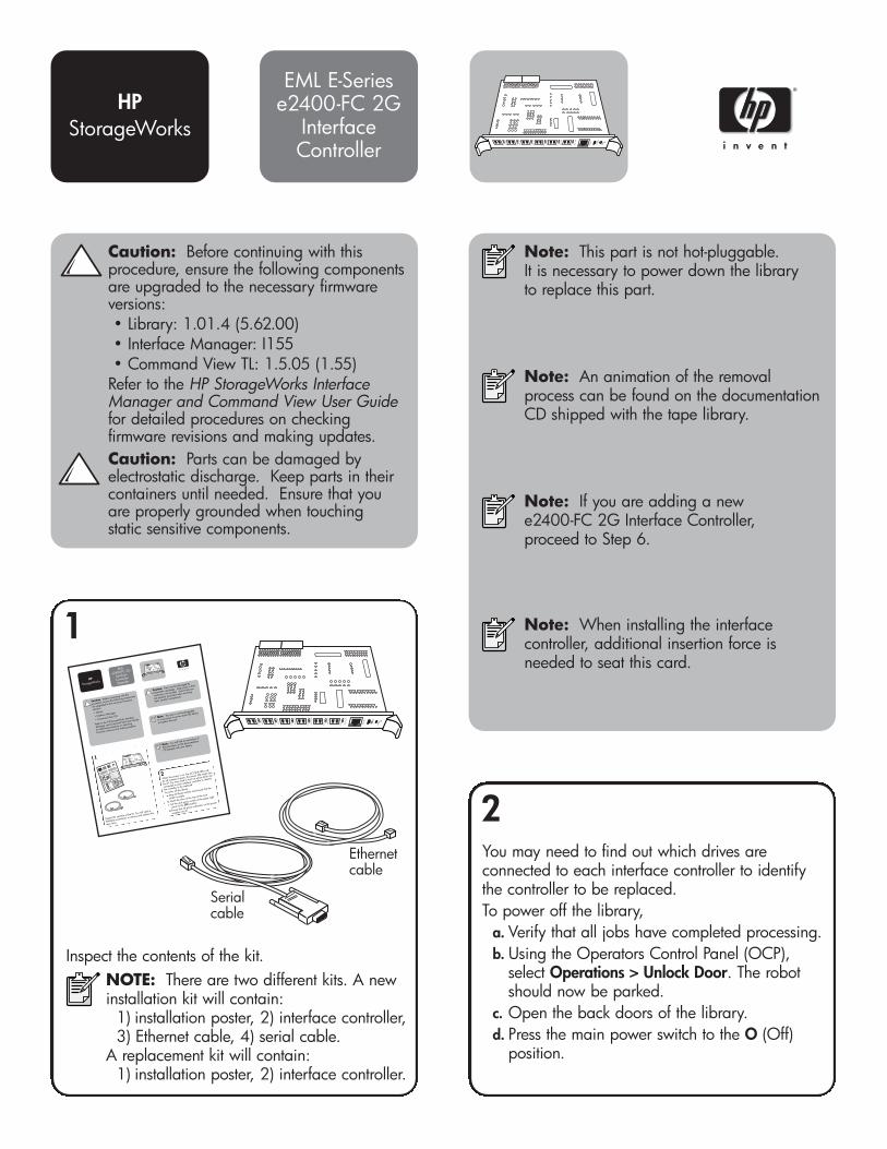
Inspect the contents of the kit. NOTE: There are two different kits. A newinstallation kit will contain:
1) installation poster, 2) interface controller, 3) Ethernet cable, 4) serial cable.
A replacement kit will contain: 1) installation poster, 2) interface controller.
You may need to find out which drives areconnected to each interface controller to identifythe controller to be replaced. To power off the library,
a. Verify that all jobs have completed processing.b. Using the Operators Control Panel (OCP),
select Operations > Unlock Door. The robotshould now be parked.
c. Open the back doors of the library.d. Press the main power switch to the O (Off)
position.
Serialcable
Ethernetcable

Removal
Installation
Locate the card in the second card cage slot in thebase module or in one of the slots in the card cageexpansion module. This card contains two HBA orswitch FC ports, four tape drive FC ports, oneEthernet port, and one serial port. You will need a#1 Phillips screwdriver to remove and replace thiscard.
3 4
5
For a new installation, remove and discard theappropriate slot cover for each controller you will beinstalling. With the power LED on the right, slide thecontroller into the appropriate slot. Push the ejectorhandles inward to fully seat the controller. Using a #1Phillips screwdriver, tighten the ejector handle screws.
6
NOTE: This installation process assumesthe tape drives have already beeninstalled.
Connect the FC cable coming from each tapedrive to a TD# port on the controller. Attach alabel to each end of the cable to mark the portdesignations. If replacing a controller, makesure you are connecting the FC cable exactlyas it was on the original controller.
7
Plug an FC cable (not supplied) into the FC 0port on the controller. Plug the other end intoeither the host bus adapter (HBA) port on a host,or into the FC switch that is connected to the host.Label both ends of the cable.
8
Noting cable locations for later reconnection,carefully disconnect the FC and Ethernet cablesfrom the interface controller by pressing on theconnector tabs and removing the cables.
Use a #1 Phillips screwdriver to loosen the captivescrews in the black ejector handles at both ends ofthe interface controller. Push the ejector handlesoutward, and then pull on them to remove theinterface controller. Place the interface controllerinto an electrostatic bag.

12
If a second host is available, plug an FC cable(not supplied) into the FC 1 port on the controller.Plug the other end into the HBA port on the hostor into the FC switch. Label both ends of thecable.
9
Plug the Ethernet cable into the Ethernet port onthe controller. Plug the other end of the Ethernetcable into one of the TO FIBRE CHANNELCONTROLLERS ports on the Interface Managercard. Attach a label to each end of the Ethernetcable to mark the port designations.
InterfaceManager
InterfaceController10
Power on the library. a. Set the library power switch at the upper
right corner to the ON position.b. Observe that all power indicators on the
power supplies show that power wasrestored.
c. Verify that the library robotics controllercard ACTIVE indicator is lit.
After installing all library components, reviewthe following checklist:
1. All tape drives have one FC cableconnected to a port in a interface controller.
2. All interface controllers have one Ethernetconnection to the Interface Manager card (TOFIBRE CHANNEL CONTROLLERS) port.
3. All interface controllers have one or twoFC connections to the SAN through the FC0or FC1 ports.
4. The Interface Manager should have oneEthernet connection from the CASCADE portto the PUBLIC port on the library roboticscontroller.
5. The Interface Manager should have oneEthernet connection from the NETWORK portto an Ethernet port on your managementstation.
6. Each power supply on the base module ortape drive expansion module is plugged intoa power strip.
7. Each power strip is plugged into a powerdistribution unit.
8. Each power distribution unit is pluggedinto an AC outlet.
11
13
Verify that the power LED and the Fibre Link LEDson the interface controller are solid green. Thelink LEDs indicate a good connection.

© Copyright 2005 Hewlett-Packard Development Company, L.P.
First Edition (May 2005)Part Number: AD560-96010
*AD560-96010*AD560-96010
Getting help• HP product information:
http://www.hp.com/products/tapestorage
• HP technical support and phone numbers: http://www.hp.com/support
• HP StorageWorks Library and Tape Tools (L&TT) diagnostic software: http://www.hp.com/support/tapetools
• Interface Manager and HP StorageWorks Command View TL:http://www.hp.com/support/cvtl
14
Close the backdoors of the library.
15
Use the Interface Manager’s command-lineinterface or the HP StorageWorks CommandView TL to verify detection of a new orreplaced interface controller, and to performconfiguration and firmware updates, ifnecessary.