emerging ideas in nanocantilever based biological sensors
TRANSCRIPT

1
Emerging Ideas in Nanocantilever based
Biological Sensors
Ankit Jain* and Muhammad Ashraful Alam
#
School of ECE, Purdue University, West Lafayette, IN, USA, 47907
e-mail: *[email protected],
Abstract
In this review article, we focus on emerging nanocantilever based biological
sensors and discuss the response of nanocantilevers towards bio-molecules capture. The
article guides the reader through various modes of operation (e.g., static or dynamic) to
detect the change in cantilever‟s characteristics (e.g., mass, stiffness, and/or surface stress)
due to adsorption of bio-molecules on cantilever surface. First, we explain the classical linear
resonant mode mass sensors and static stress based sensors. The effect of operating the
cantilever in nonlinear regime is then illustrated through examples of bifurcation based mass
sensors and electromechanical coupling based Flexure-FET biosensors. We believe that a
new class of nonlinear sensors, with their extraordinary sensitivity towards bio-molecules
capture, could be the potential candidate for low cost point-of-care applications.
1. INTRODUCTION
Detection of biological molecules e.g., viruses, proteins, DNA, etc., is essential
for food safety, early warning of biological attack, early stage diagnosis of cancer,
and genome sequencing. Nanoscale devices are widely regarded as a potential
candidate for ultra-sensitive, low-cost, label-free detection of bio-molecules and are
considered as a technology alternative to the existing chemical or optical detection
schemes. Label-free schemes detect bio-molecules using their intrinsic properties,
e.g., size, mass or charge of a molecule, instead of using extrinsic optical or
magnetic labels attached to the target molecule. Among the various label-free
technologies, significant research has focused on developing ultra-sensitive
biological sensors based on nanocantilevers [1], [2].
The use of a cantilever as a sensor dates back to 1943 when Norton proposed a
hydrogen gas sensor based on a cantilever [3]. The opportunity to develop the
cantilever as a highly sensitive biosensor, however, had to wait the invention and
wide-spread adoption of atomic force microscope (AFM) [4]. An AFM measures
the forces between the tip of a cantilever and the sample surface using the tip
deflection (contact mode AFM) or changes in the resonance frequency of a
vibrating cantilever (dynamic mode AFM). As we will see in Sec. 2, nanocantilever
based biosensors operate in a closely related principle, where interaction with
biological molecules changes the bending (static mode) or resonance frequency

2
(resonant mode) of the cantilever [5]. Note that these mechanical sensors offer an
advantage of detecting both charged as well as neutral bio-molecules; in contrast,
Fig.1: (a) Schematic of a generic biological sensor operating in fluidic environment. The
receptor, target and parasitic molecules are also shown. (b) Drawing of a nanocantilever in
which capture of target molecules changes the cantilever‟s static or dynamic response
through change in the mass, stiffness and/or surface stress. (c) A chart showing various linear
and nonlinear cantilever biosensors to be discussed in this article. 𝑆 is the sensitivity of
respective biosensors and 𝑁𝑠 is the areal density of captured bio-molecules on the cantilever
surface.
their electronic counterpart, e.g., ISFETs (Ion Sensitive Field Effect Transistors [6])
can only detect charged molecules. Today, cantilever-based devices find
applications in broad range of fields such as communication, computation, optics,
scanning probe microscopy, and sensing. Specific examples include RF-MEMS
capacitive/ohmic switches [7], varactors, tunable oscillators [8], NEMS relays [9],
NEMFET [10], deformable mirrors [11], displays [12], accelerometers [13], and
chemical/gas sensors. In this article, however, we only focus on the use of
cantilever as a biological sensor, and discuss both classical and emerging modes of
biosensor operation.
Figures 1(a)-(b) show the schematic of a sensor surface operating in a fluidic
environment. The sensor surface is functionalized with receptor molecules so that it

3
can subsequently conjugate to the target molecules (without any optical or magnetic
labels) contained in the fluid. For example, if the target is an antibody, then receptor
is corresponding antigen, or if the target is a DNA base (e.g., A), then receptor is its
conjugate base (e.g., C). The specific binding of the target and receptor molecules
changes the sensor characteristics and the change is measured as a signature of
detection. For example, the binding may induce an additional surface stress or may
change the mass or stiffness of the cantilever, resulting in bending or change in the
resonance frequency [5].
There are three key metrics of any sensing scheme (electronic or mechanical),
namely, response time [14], selectivity [15], and sensitivity [16]. Response time is
the time required to capture a certain number of target molecules to get a detectable
output signal. Interestingly, response time depends on the geometry of the sensor
surface and cylindrical geometry allows the smallest response time [14]. On the
other hand, selectivity is associated with the problem of non-specific binding, i.e.,
binding of parasitic molecules with receptor molecules, producing a “false-
positive” signal. In a highly selective sensor, receptor molecules should only bind
to the target molecules and not to any other molecules in the solution. Finally,
sensitivity can be defined in number of ways; in general, it is measured as the
change in the sensor characteristics (e.g., resonance frequency of a cantilever [5] or
drain current of ISFET [17]) in response to the capture of a given number of target
molecules. Note that, response time and selectivity of a sensor do not depend on the
sensing scheme, whereas sensitivity depends on the sensing scheme. Therefore, in
this article, we only discuss sensitivity related issues of nanocantilever based
biological sensors. Note that, sensitivity of the sensor depends whether it is
operated in linear or nonlinear regime. Figure 1(c) summarizes all linear and
nonlinear cantilever biosensors to be discussed in the following sections.
The rest of the article is organized as follows. In section 2, we discuss the spring-
mass model of cantilever and illustrate classical mass and stress based sensors in
section 3. We then present the emerging nonlinear biosensors like bifurcation based
mass sensors and Flexure-FET in section 4. We finally conclude in section 5.
2. CANTILEVER BASED SENSORS AS SPRING MASS SYSTEM
The static as well as dynamic response of cantilever based sensors is best
described by Euler-Bernoulli beam equation [18]. In this article, we however use a
lumped parameter, spring-mass system (Fig. 2(b)) of a cantilever to illustrate its key
features. The equation of motion of lumped parameter spring-mass system is given
by-
𝑚𝑑2𝑦
𝑑𝑡2+
𝑚𝜔0
𝑄
𝑑𝑦
𝑑𝑡− 𝑘 𝑦0 − 𝑦 − 𝑘′ 𝑦0 − 𝑦 3 = 𝐹𝑒𝑥𝑡 , (1)
4
where 𝑚 is the effective mass of the cantilever, 𝑦 is the position of vibrating
cantilever, 𝑡 is time, 𝜔0 is the natural frequency of cantilever, 𝑄 is the quality
factor, 𝑘 is the effective spring constant of the cantilever such that 𝜔0 = 𝑘/𝑚, 𝑦0
is the position of the cantilever in its rest position, and 𝑘′ is the constant associated
with cubic nonlinearity of spring. Note that, 𝑘 =𝛼𝐸𝑊𝐻3
(1−𝜈)𝐿3 is the spring constant of
the cantilever where 𝛼 is a geometrical factor, 𝐸 is the Young‟s modulus, 𝜈 is the
Poisson‟s ratio, 𝑊 is the width, 𝐻 is the thickness, and 𝐿 is the length. 𝐹𝑒𝑥𝑡 is the
external force acting on the cantilever, e.g., surface forces, electrostatic forces, etc.
Historically, the cantilever based sensors have been operated without applying any
external force (i.e., 𝐹𝑒𝑥𝑡 = 0) and in linear response regime i.e., 𝑘′ ≈ 0 (section 3).
We will explore the nonlinear 𝐹𝑒𝑥𝑡 ≠ 0 & 𝑘 ′ ≠ 0 operation in section 4.
3. CLASSICAL LINEAR BIOSENSORS
3.1 Resonant mode mass sensors
In resonant mode sensing, vibrating nanocantilever can be used as a
microbalance and bio-molecules can be detected by observing the change in
dynamic response of the cantilever [1], [5]. Fundamentally, dynamic response of a
cantilever is governed by its resonance frequency 𝑓0 that is given by (using Eq. 1
with 𝑘′ = 0 and 𝐹𝑒𝑥𝑡 = 0)-
𝑓0 =𝜔0
2𝜋=
1
2𝜋
𝑘
𝑚. (2)
Once the target molecules are captured, change in 𝑚 (and/or 𝑘) shifts the resonance
frequency (𝛥𝑓) to indicate the capture of bio-molecules. Experimentally, resonance
frequency of the cantilever can be obtained by measuring the amplitude-frequency
spectrum of vibrating cantilever using optical techniques. Figure 2(c) shows
amplitude-frequency spectrum of a vibrating cantilever for three different
conditions: before functionalizing with receptor molecules (blue circles), after
functionalizing (red squares), and after capture of target molecules (black diamond)
[19]. By definition, the peak in the amplitude-frequency spectrum corresponds to
the resonance frequency 𝑓0. As expected, resonance frequency decreases following
the attachment of receptor molecules due to the added mass on the cantilever. It
decreases further after capture of target molecules by receptor molecules due to
further increase in the mass. Change in the resonance frequency due to the
adsorption of the molecules can be obtained using Eq. (2), and is given by-
𝛥𝑓
𝑓0
≈ −𝛥𝑚
2𝑚+
𝛥𝑘
2𝑘, (3)
where 𝛥𝑚 is the mass of added molecules and 𝛥𝑘 is the change in stiffness. Figure
2(d) shows Δ𝑓 as a function of Δ𝑚 for two different cantilevers [20] and linear

5
dependence of Δ𝑓 on Δ𝑚 confirms Eq. 3 (assuming Δ𝑘 = 0). Equation (3)
suggests that the sensitivity 𝑆 ≡ Δ𝑓/𝑓0 of nanocantilever biosensors can only vary
Fig. 2: Dynamic resonant mode sensing using nanocantilever. (a) Schematic of a vibrating
cantilever whose resonance frequency changes due to capture of target bio-molecules. (b)
Equivalent spring-mass model of the vibrating cantilever. (c) Amplitude vs. frequency
spectrum of a free standing cantilever (○), after receptor molecules attachment (), and after
capture of target molecules (◊) [19]. (d) Change in resonance frequency as a function of
added mass of the bio-molecules for two different cantilevers [20] .
linearly with Δ𝑚 (assuming Δ𝑘 = 0) and therefore 𝑆 ∝ 𝑁𝑠 with 𝑁𝑠 being the areal
density of captured bio-molecules on cantilever surface. We emphasize that these
biosensors – with careful design and appropriate instrumentation – can be
extraordinarily sensitive; indeed, zeptogram mass detection has been reported [21].
It is also important to realize that the linear sensitivity with Δ𝑚 is achieved only if
the change in stiffness (Δ𝑘) due to capture of bio-molecules is negligible (Eq. (3)).
In general, the capture of target molecules increases 𝑘 [19]. If 𝛥𝑘 compensates Δ𝑚,
Eq. (3) suggests that there may be no change in resonance frequency at all (i.e.,
Δ𝑓~0) and the sensitivity could be vanishingly small. Therefore, one must
independently measure the change in 𝑘 to decouple the „mass effect‟ from „stiffness
effect‟, so that the mass of the adsorbed molecule can be correctly estimated [22],
[23].
The sharpness of the peak (or the width of the amplitude-frequency spectrum)
vibrating cantilever is characterized by its quality factor (𝑄) (Eq. (1)) and depends
on the damping due to the surrounding medium. As 𝑄 increases, resonance peak
6
becomes sharper and width of the spectrum is reduced. Unfortunately, value of
minimum detectable Δ𝑓 increases as 𝑄 is reduced [24]. Therefore, measurements in
vacuum or air can be more sensitive (capable of resolving small Δ𝑓 and therefore
smaller Δ𝑚) as compared that in fluidic environment [24]. This dependence of Δ𝑓
on 𝑄 has inspired design of suspended microchannel resonators [25–27] that do not
suffer from 𝑄 degradation due to the surrounding fluid. Such resonators are
operated either in vacuum or in air and the fluid containing the target bio-molecules
flows through the microchannel, embedded within the cantilever itself.
To summarize, the response of resonant mode nanocantilever based biosensors is
linear with respect to the added mass of bio-molecules. Minimum detectable mass
depends on the quality factor of the vibrating cantilever. And, suspended
microchannel resonators can detect lower masses due to their high quality factors.
3. 2 Stress based static mode sensors
Another class of nanocantilever sensor involves operation in the static mode, in
which capture of target molecules introduces a surface stress [5]. Changes in the
surface stress can be the result of an adsorption process or electrostatic interactions
between charged molecules on the surface or conformational changes of the
adsorbed molecules. This change in the surface stress bends the cantilever as shown
in Fig. 3(a). The deflection of the tip of the cantilever Δ𝑦 is then measured as a
signature of bio-molecules capture. Stoney‟s equation [28] relates the deflection Δ𝑦
with the change in the surface stress Δ𝜎 as follows-
Δ𝑦 =3𝐿2 1 − 𝜈
𝐸𝐻2Δ𝜎, (4)
where 𝐿 is the length, 𝜈 is the Poisson‟s ratio, 𝐸 is the Young‟s modulus, and 𝐻 is
the thickness of the cantilever. Note that, Eq. (4) can be obtained from Eq. (1)
(with time derivatives and 𝑘′ = 0) with appropriately chosen 𝐹𝑒𝑥𝑡 = −3𝛼𝑊𝐻
𝐿Δ𝜎.
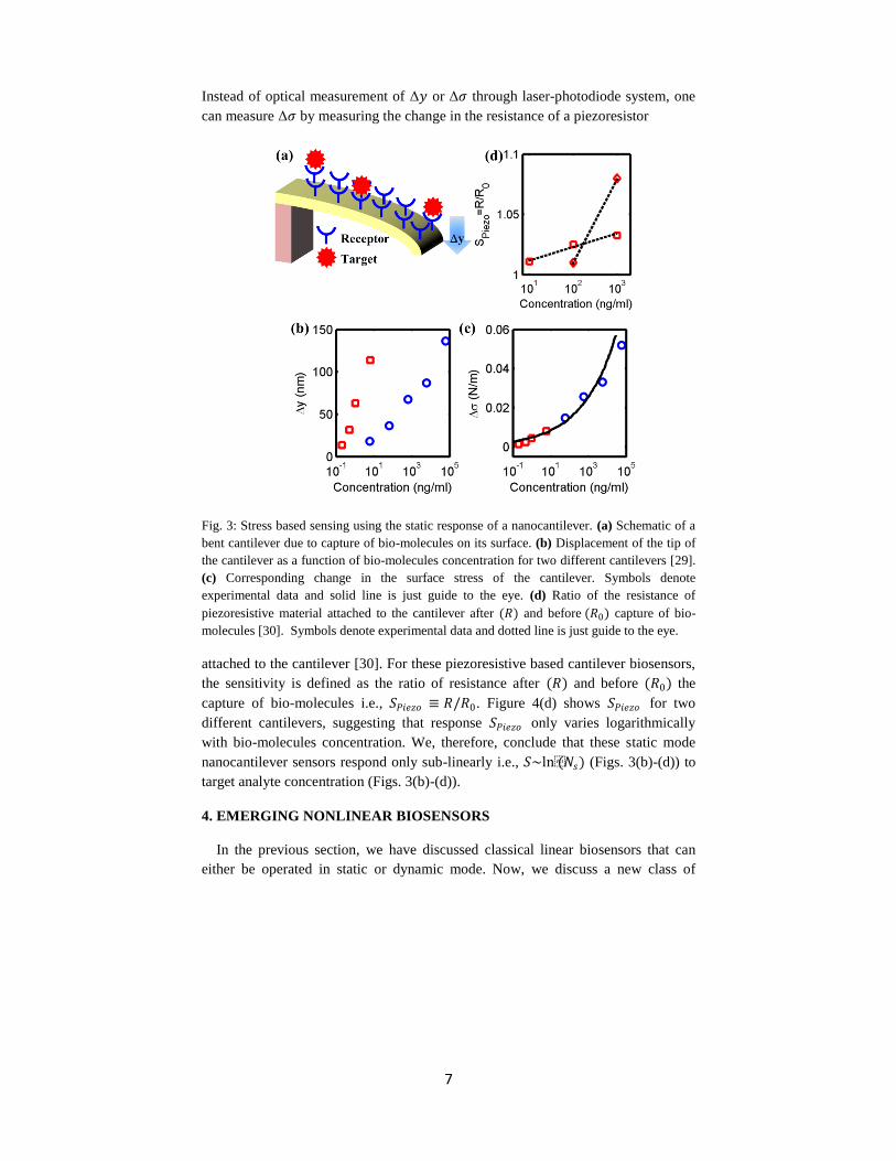
Deflection Δ𝑦 of the cantilever tip can be measured optically (e.g., using a laser
and photodiode) or electrically (e.g. using an integrated piezo-resistor). Figure 3(b)
shows deflection Δ𝑦 as a function of the target bio-molecules concentration in the
solution for two different cantilevers having different geometrical dimensions [29].
The response Δ𝑦 is sub-linear with respect to the concentration and it depends on
the geometrical dimensions of the cantilever. Using Eq. (4) and data shown in Fig.
3(b), Δ𝜎 can be calculated and is shown in Fig. 3(c). Interestingly, Δ𝜎 for two
different cantilevers follow a single curve (Fig. 3(c)), suggesting that Δ𝜎 only
depends on the concentration of the bio-molecules and not on the cantilever
properties.
7
Instead of optical measurement of Δ𝑦 or Δ𝜎 through laser-photodiode system, one
can measure Δ𝜎 by measuring the change in the resistance of a piezoresistor
Fig. 3: Stress based sensing using the static response of a nanocantilever. (a) Schematic of a
bent cantilever due to capture of bio-molecules on its surface. (b) Displacement of the tip of
the cantilever as a function of bio-molecules concentration for two different cantilevers [29].
(c) Corresponding change in the surface stress of the cantilever. Symbols denote
experimental data and solid line is just guide to the eye. (d) Ratio of the resistance of
piezoresistive material attached to the cantilever after (𝑅) and before (𝑅0) capture of bio-
molecules [30]. Symbols denote experimental data and dotted line is just guide to the eye.
attached to the cantilever [30]. For these piezoresistive based cantilever biosensors,
the sensitivity is defined as the ratio of resistance after (𝑅) and before (𝑅0) the
capture of bio-molecules i.e., 𝑆𝑃𝑖𝑒𝑧𝑜 ≡ 𝑅/𝑅0. Figure 4(d) shows 𝑆𝑃𝑖𝑒𝑧𝑜 for two
different cantilevers, suggesting that response 𝑆𝑃𝑖𝑒𝑧𝑜 only varies logarithmically
with bio-molecules concentration. We, therefore, conclude that these static mode
nanocantilever sensors respond only sub-linearly i.e., 𝑆~ln(𝑁𝑠) (Figs. 3(b)-(d)) to
target analyte concentration (Figs. 3(b)-(d)).
4. EMERGING NONLINEAR BIOSENSORS
In the previous section, we have discussed classical linear biosensors that can
either be operated in static or dynamic mode. Now, we discuss a new class of

8
emerging nonlinear biosensors that utilize inherent instability of nanocantilever
static/dynamic response to achieve better sensitivity towards bio-molecules capture.
4. 1 Bifurcation based mass sensors
As discussed above, classical resonant mode biosensors rely on the change in
resonance frequency due to capture of bio-molecules. Note that, when operated in
the linear regime (under small amplitude limit), the amplitude-frequency spectrum
is symmetric and bell-shaped, as shown in Fig. 4(a). In this case, detection of bio-
molecules is achieved by observing the shift in the peak (i.e., Δ𝑓, see Fig. 4(a)), as
discussed in Sec 3.1.
In the large amplitude nonlinear response regime, however, higher order spring
nonlinearities (𝑖. 𝑒. , 𝑘′ ≠ 0 in Eq. (1)) distorts the response, and amplitude-
frequency spectrum is no longer symmetric [31]. Figure 4(b) shows one such
amplitude-frequency spectrum with softening nonlinearity (𝑘 ′ < 0 and 𝐹𝑒𝑥𝑡 =
𝐹0sin(2𝜋𝑓𝑒𝑥 𝑡) in Eq. (1) with 𝐹0 being the excitation amplitude and 𝑓𝑒𝑥 is the
excitation frequency) for a Duffing like resonator. Interestingly, spectrum exhibits
sudden jumps at points 𝑃 and 𝑆 representing saddle-node bifurcations. The
hysteretic behavior shown in Fig. 4(b) is achieved, when 𝐹0 > 𝐹𝑐 with 𝐹𝑐 being a
critical threshold. Kumar et al., has proposed a bifurcation based mass sensor that
utilizes these sudden jumps and rely on the shift in the amplitude and not on the
shift in the frequency to signal bio-molecules capture [32]. In bifurcation based
sensing, the resonator is operated near one of the critical point (say 𝑃). Capture of
the bio-molecules reduces the fundamental frequency 𝑓0 and increases 𝑓𝑒𝑥 /𝑓0
resulting in the sudden change in the amplitude of oscillation Δ𝐴, as shown in Figs.
4(b)-(c). Measurement of Δ𝐴 (using laser Doppler vibrometer (LDV)) is then used
as the signature of capture of bio-molecules. It should be appreciated that this
sensing scheme is very sensitive to small quantities of added molecules due to the
amplification offered by inherent instability of mechanical system.
4. 2 Electromechanical coupling based Flexure-FET biosensors
We have discussed both linear and nonlinear cantilever based biosensors that rely
on optical readout of 𝑦 or 𝑓0. Now, we discuss a new class of nonlinear biosensors
called Flexure-FET [16] that utilize the electromechanical coupling between a
suspended beam and a field effect transistor to achieve much higher sensitivity
compared to traditional biosensors. Flexure-FET consists of a channel biased
through a thin-film suspended gate (Fig. 5(a)). While the structure is similar to that
of a suspended-gate FET [33], NEMFET [10] or resonant gate transistor [34], we
call the sensor Flexure-FET to emphasize its distinctive nonlinear operation
specifically optimized for ultrasensitive detection of bio-molecules. In a Flexure-

9
FET, any change in the mechanical property of the suspended gate is directly
reflected in the change of drain current of underneath field effect transistor and
Fig. 4: Comparison of classical linear mass sensors with nonlinear bifurcation based mass
sensors. Amplitude-frequency spectrum of (a) classical linear and (b) bifurcation based mass
sensors proposed in ref. [32]. (c) Amplitude as a function of time in bifurcation based mass
sensors. Classical sensors rely on the change in frequency Δ𝑓 whereas bifurcation based
sensors rely on change in the amplitude Δ𝐴 due to capture of bio-molecules.
thereby enables electrical readout. As shown in Fig. 5(b), ultra high sensitivity
arises from the coupling of two nonlinear responses, namely (i) spring-softening
[35] in which stiffness decreases nonlinearly with the applied gate bias 𝑉𝐺 and
vanishes at the pull-in point (for detailed discussions on pull-in instability, see Ref.
[36], [37]), and (ii) sub-threshold electrical conduction [38] in which current
depends exponentially on the surface potential. Such nonlinear electro-mechanical
coupling enables exponentially high sensitivity for Flexure-FET sensors, which is
fundamentally unachievable by exclusive use of existing nanoscale electronic or
mechanical biosensors.
It should be noted that from a mechanical perspective, Flexure-FET operates
close to pull-in instability, a critical point. Similar critical point sensing has also
been reported for vapor sensors that operates close to bucking-instability [39], [40]
and for mass sensor that operates close to saddle-node bifurcation [32] (discussed in
Sec. 4.1) and their higher sensitivity have been confirmed experimentally.
However, beyond the critical point sensing, the integrated transistor-action in the
sub-threshold regime provides the Flexure-FET an additional exponential
sensitivity (and simpler DC read-out) that could not be achieved by the classical
nonlinear sensor schemes.
The operating principle of Flexure-FET can be understood based on a spring-
mass system coupled to electrostatic actuation, see Fig. 6 [10], [34]. With the
application of gate bias 𝑉𝐺 , the gate moves downward towards the dielectric
(𝑦 𝑣𝑠. 𝑉𝐺 curve in Fig. 5(b)) and the corresponding increase in gate capacitance is
reflected in the increased drain current 𝐼𝐷𝑆 , as shown in Fig. 5(b). The static

10
behavior of the device is dictated by the balance of spring and electrostatic forces
(Eq. (1) with time derivatives zero and 𝑘 ′ = 0), i.e.,
Fig. 5: Static stiffness based nonlinear electromechanical sensing with electrical readout. (a)
Schematic of Flexure-FET bio-sensor and (b) 𝑦 and 𝐼𝐷𝑆 vs. gate voltage characteristic of
Flexure-FET. 𝑉𝑇 is the threshold voltage and 𝑉𝑃𝐼 is the pull-in voltage of Flexure-FET.
𝑘 𝑦0 − 𝑦 = 𝐹𝑒 ≡1
2𝜖0𝐸𝑎𝑖𝑟
2 𝐴, (5)
where 𝐸𝑎𝑖𝑟 is the electric field in the air, and 𝐴 = 𝑊𝐿 is the area of the gate
electrode. The electric field below the membrane 𝐸𝑎𝑖𝑟 is equal to 𝜖𝑠𝐸𝑠(𝜓𝑠),
where, 𝜖𝑠 is the dielectric constant of the substrate, and
𝐸𝑠 𝜓𝑠 = 2𝑞𝑁𝐴
𝜖0𝜖𝑠
𝜓𝑠 + 𝑒−𝑞𝜓𝑠𝑘𝐵𝑇 − 1
𝑘𝐵𝑇
𝑞
− 𝑛𝑖
𝑁𝐴
2
𝜓𝑠 − 𝑒𝑞𝜓𝑠𝑘𝐵𝑇 − 1
𝑘𝐵𝑇
𝑞
12
, (6𝑎)
where, 𝐸𝑠(𝜓𝑠) is the electric field at the substrate-dielectric interface (see Ref. [38]
page 64 for a detailed derivation of Eq. 6(a)), 𝜓𝑠 is the surface potential, 𝑞 is the
charge of an electron, 𝑁𝐴 is the substrate doping, 𝑘𝐵 is the Boltzmann constant, 𝑇 is
the absolute temperature, and 𝑛𝑖 is the intrinsic carrier concentration in the

11
substrate. The voltage drop in air (𝑦𝜖𝑠𝐸𝑠 𝜓𝑠 ), dielectric 𝑦𝑑
𝜖𝑑𝜖𝑠𝐸𝑠 𝜓𝑠 , and
substrate (𝜓𝑠) can be related to the applied gate bias 𝑉𝐺 as follows-
Fig. 6 (a)-(b) Equivalent spring-mass model of Flexure-FET. Stiffness changes from 𝑘 to
𝑘 + Δ𝑘 after the capture of biomolecules, and therefore, position of gate changes from 𝑦 to
𝑦 + Δ𝑦 which results in the modulation of drain current from 𝐼𝐷𝑆1to 𝐼𝐷𝑆2.
𝑉𝐺 = 𝑦 +𝑦𝑑
𝜖𝑑
𝜖𝑠𝐸𝑠(𝜓𝑠) + 𝜓𝑠 , (6𝑏)
where, 𝑦𝑑 is the dielectric thickness. Equations (5)-(6) are solved self-consistently
for 𝑦 and 𝜓𝑠 at each 𝑉𝐺 . The corresponding inversion charge density 𝑄𝑖 in the
channel and drain current (𝐼𝐷𝑆) are given by,
𝑄𝑖 =𝑞𝑛𝑖
2
𝑁𝐴
𝑒
𝑞𝜓𝑘𝐵𝑇 − 1
𝐸𝑠(𝜓)𝑑𝜓
𝜓𝑠
0
, (7)
𝐼𝐷𝑆 = 𝜇𝑛𝐿𝑄𝑖
𝑉𝐷𝑆
𝑊, (8)
where, 𝜇𝑛 is the channel mobility for electrons, 𝑉𝐷𝑆 is the applied drain to source
voltage. Figure 5(b) shows the steady-state response of Flexure-FET as a function
of biasing voltage 𝑉𝐺 , obtained from the numerical simulations of Eqs. (5)-(8).
For transduction, Flexure-FET biosensor utilizes the change in suspended-gate
stiffness from 𝑘 to 𝑘 + Δ𝑘, due to the capture of bio-molecules. The change in
stiffness due to the capture of bio-molecules has been demonstrated by several
recent experiments of mass sensing using nanocantilever based resonators [19],
[41–43]. This well-known observation of stiffness change has been attributed to the

12
change in the membrane thickness, Young‟s modulus, and/or surface stress of the
beam [19], [41–43]. Indeed, Craighead in Ref. [44] suggests its use as a basis of a
new class of mechanical biosensor.
Fig. 7: Change in the sensor characteristics due to capture of target molecules on the surface
of the gate, (a) 𝑦 vs. 𝑉𝐺 before and after capture, and (b) corresponding change in the
position of gate electrode Δ𝑦 vs. 𝑉𝐺 . Δ𝑦 increases rapidly near pull-in due to spring-softening
effect. The capture of target molecules is directly mirrored in the change in 𝐼𝐷𝑆 . (c) 𝐼𝐷𝑆 vs. 𝑉𝐺
for before and after capture, and (d) corresponding ratio of the two currents 𝐼𝐷𝑆1 (before
capture) and 𝐼𝐷𝑆2 (after capture) as a function of Δ𝑦. Orders of magnitude change in 𝐼𝐷𝑆 can
be easily achieved for typical surface density of 𝑁𝑠 = 5 ∗ 1012𝑐𝑚−2, projected area of the
bio-molecule, 𝐴𝑡 = 𝜋𝑅𝑡2 with 𝑅𝑡 = 1𝑛𝑚, and𝐻𝑡 = 5.1𝑛𝑚. These parameters translate to just
an equivalent Δ𝑘~6%. The device considered has the following typical parameters: 𝐿 =
4𝜇𝑚, 𝑊 = 1𝜇𝑚, 𝐻 = 40𝑛𝑚, 𝐸 = 200𝐺𝑃𝑎, 𝑦0 = 100𝑛𝑚, 𝑦𝑑 = 5𝑛𝑚, 𝜖𝑠 = 11.7, 𝜖𝑑 = 3.9,
𝑁𝐴 = 6 ∗ 1016𝑐𝑚−3.
In the following analysis, we model change in 𝑘 by the change in the effective
thickness 𝐻 of the gate (𝛥𝐻), although it should be stressed that the conclusions do
not depend on the particular hypothesis regarding 𝛥𝑘. For now, we ignore the
details of the spatial distribution of molecules associated with random sequential

13
adsorption [15], and assume a uniform distribution of adsorbed molecules on the
sensor surface. Therefore, the conservation of volume suggests Δ𝐻 = 𝑁𝑠𝐴𝑡𝐻𝑡 ,
where 𝑁𝑠 is the areal density, 𝐴𝑡 is the effective cross-sectional area, and 𝐻𝑡 is the
effective thickness of the target molecule. Using the fact that 𝑘 =𝛼𝐸𝑊𝐻3
(1−𝜈)𝐿3, change in
stiffness Δ𝑘 due to Δ𝐻 (≪ 𝐻) can be related to adsorbed molecule density 𝑁𝑠 as
follows,
Δ𝑘
𝑘≈
3𝑁𝑠𝐴𝑡𝐻𝑡
𝐻 . (9)
It can be shown that if Flexure-FET is operated close to pull-in and in sub-threshold
regime, sensitivity 𝑆 (using Eqs. (5)-(9), see Ref. [16] for details of derivation) is
given by-
𝑆𝐹𝑙𝑒𝑥𝑢𝑟𝑒 ≡𝐼𝐷𝑆1
𝐼𝐷𝑆2≈ exp 𝛾1 𝑁𝑠 − 𝛾2𝑁𝑠 , (10 )
where 𝛾1/𝛾2 are two sensor geometry dependent constant. Equation 10 confirms
the exponential sensitivity of Flexure-FET towards bio-molecules capture.
The results for the change in sensor characteristics due to the capture of
bio-molecules are summarized in Fig. 7. For example, Fig. 7(a) shows 𝑦 vs. 𝑉𝐺
before and after capture of target molecules. After the capture, gate moves up (for a
fixed 𝑉𝐺) due to increased restoring spring force (because of increase in 𝑘, see Fig.
7(a)). Interestingly, change in gate position Δ𝑦 is maximum close to pull-in due to
spring-softening effect, as shown in Fig. 7(b). The change in gate position Δ𝑦 is
directly reflected in change in 𝐼𝐷𝑆 . Figure 7(c) shows 𝐼𝐷𝑆 vs. 𝑉𝐺 before and after
capture of bio-molecules. Interestingly, 𝐼𝐷𝑆 decreases after capture due to increased
separation between the gate and the dielectric (hence decreased capacitance). The
corresponding ratio of the currents 𝐼𝐷𝑆1 (before capture) and 𝐼𝐷𝑆2 (after capture)
increases exponentially with 𝛥𝑦 (Fig. 7(d)), and becomes maximum near pull-in.
5. CONCLUSIONS
In this review article, we have discussed various ways of detecting bio-
molecules using nanocantilevers. Classical resonant mode biosensors detect the
change in the resonance frequency of vibrating cantilever and require complex
optical instrumentation for detection, especially when very high sensitivity is
desired. Stress based static mode sensors detect the deflection of the tip of the
cantilever and responds linearly to change in the stress. To achieve better sensitivity
than achieved by classical linear biosensors, critical-point nonlinear bio-sensors
have started to appear in the literature. For example, we discussed bifurcation based
mass sensors that operate close to a saddle-node bifurcation. Finally, we have
discussed Flexure-FET biosensor that integrates a transistor for direct electrical

14
readout and utilizes nonlinear electromechanical coupling for its exponential
sensitivity. We believe that these critical point nonlinear biosensors with electrical
readout will offer opportunity to integrate highly sensitive sensors in low cost
point-of-care applications.
References
[1] J. L. Arlett, E. B. Myers, and M. L. Roukes, “Comparative advantages of
mechanical biosensors,” Nature Nanotechnology, vol. 6, pp. 203-215, 2011.
[2] J. Tamayo, P. M. Kosaka, J. J. Ruz, A. San Paulo, and M. Calleja,
“Biosensors based on nanomechanical systems.,” Chemical Society reviews,
vol. 42, no. 3, pp. 1287-311, Jan. 2013.
[3] F. J. Norton, “Gas Analyzer,” U.S. Patent 2,307,8001943.
[4] G. Binnig and C. F. Quate, “Atomic Force Microscope,” Physical Review
Letters, vol. 56, no. 9, pp. 930-933, Mar. 1986.
[5] N. V. Lavrik, M. J. Sepaniak, and P. G. Datskos, “Cantilever transducers as
a platform for chemical and biological sensors,” Review of Scientific
Instruments, vol. 75, pp. 2229-2253, 2004.
[6] P. Bergveld, “Thirty years of ISFETOLOGY - What happened in the past
30 years and what may happen in the next 30 years,” Sensors and Actuators
B-Chemical, vol. 88, pp. 1-20, 2003.
[7] G. M. Rebeiz and J. B. Muldavin, “RF MEMS switches and switch
circuits,” IEEE Microwave Magazine, vol. 2, pp. 59-71, 2001.
[8] J. J. Yao, “RF MEMS from a device perspective,” Journal of
Micromechanics and Microengineering, vol. 10, p. R9-R38, 2000.
[9] V. Pott, H. Kam, R. Nathanael, J. Jeon, E. Alon, and T.-J. King Liu,
“Mechanical Computing Redux: Relays for Integrated Circuit
Applications,” Proceedings of the IEEE, vol. 98, no. 12, pp. 2076-2094,
Dec. 2010.
[10] H. Kam, D. T. Lee, R. T. Howe, and T.-J. King, “A new nano-electro-
mechanical field effect transistor (NEMFET) design for low-power
electronics,” in IEDM, 2005, pp. 463-466.
[11] T. Bifano, “Adaptive imaging: MEMS deformable mirrors,” Nature
Photonics, vol. 5, no. 1, pp. 21-23, Jan. 2011.

15
[12] Q. M. Technologies, “Value Proposition of mirasol Displays,” 2011.
[13] L. M. Roylance and J. B. L. A.-E. Angell, “A batch-fabricated silicon
accelerometer,” IEEE Transactions on Electron Devices, vol. 26, pp. 1911-
1917, 1979.
[14] P. R. Nair and M. A. Alam, “Performance limits of nanobiosensors,”
Applied Physics Letters, vol. 88, no. 23, p. 233120, Jun. 2006.
[15] P. R. Nair and M. A. Alam, “Theory of „Selectivity‟ of label-free
nanobiosensors: A geometro-physical perspective.,” Journal of applied
physics, vol. 107, no. 6, p. 64701, Mar. 2010.
[16] A. Jain, P. R. Nair, and M. A. Alam, “Flexure-FET biosensor to break the
fundamental sensitivity limits of nanobiosensors using nonlinear
electromechanical coupling.,” Proceedings of the National Academy of
Sciences of the United States of America, vol. 109, no. 24, pp. 9304-8, Jun.
2012.
[17] P. R. Nair and M. A. Alam, “Screening-limited response of
nanobiosensors,” Nano Letters, vol. 8, pp. 1281-1285, 2008.
[18] C. Ziegler, “Cantilever-based biosensors,” Analytical and Bioanalytical
Chemistry, vol. 379, no. 7-8, pp. 946-959, 2004.
[19] A. K. Gupta et al., “Anomalous resonance in a nanomechanical biosensor,”
Proceedings of the National Academy of Sciences of the United States of
America, vol. 103, pp. 13362-13367, 2006.
[20] K. L. Ekinci and M. L. Roukes, “Nanoelectromechanical systems,” Review
of Scientific Instruments, vol. 76, 2005.
[21] Y. T. Yang, C. Callegari, X. L. Feng, K. L. Ekinci, and M. L. Roukes,
“Zeptogram-scale nanomechanical mass sensing,” Nano Letters, vol. 6, pp.
583-586, 2006.
[22] F. Sadeghian, H. Goosen, A. Bossche, and F. van Keulen, “Application of
electrostatic pull-in instability on sensing adsorbate stiffness in
nanomechanical resonators,” Thin Solid Films, vol. 518, pp. 5018-5021,
2010.
[23] E. Gil-Santos et al., “Nanomechanical mass sensing and stiffness
spectrometry based on two-dimensional vibrations of resonant nanowires,”
Nature Nanotechnology, vol. 5, pp. 641-645, 2010.

16
[24] K. L. Ekinci, “Ultimate limits to inertial mass sensing based upon
nanoelectromechanical systems,” Journal of Applied Physics, vol. 95, no. 5,
p. 2682, Mar. 2004.
[25] T. P. Burg et al., “Weighing of biomolecules, single cells and single
nanoparticles in fluid.,” Nature, vol. 446, no. 7139, pp. 1066-9, May 2007.
[26] J. Lee, W. Shen, K. Payer, T. P. Burg, and S. R. Manalis, “Toward attogram
mass measurements in solution with suspended nanochannel resonators.,”
Nano letters, vol. 10, no. 7, pp. 2537-42, Jul. 2010.
[27] J. L. Arlett and M. L. Roukes, “Ultimate and practical limits of fluid-based
mass detection with suspended microchannel resonators,” Journal of
Applied Physics, vol. 108, no. 8, p. 084701, Oct. 2010.
[28] G. G. Stoney, “The Tension of Metallic Films Deposited by Electrolysis,”
Proc. R. Soc. Lond. A, vol. 82, p. 172, 1909.
[29] G. H. Wu, R. H. Datar, K. M. Hansen, T. Thundat, R. J. Cote, and A.
Majumdar, “Bioassay of prostate-specific antigen (PSA) using
microcantilevers,” Nature Biotechnology, vol. 19, pp. 856-860, 2001.
[30] K. W. Wee et al., “Novel electrical detection of label-free disease marker
proteins using piezoresistive self-sensing micro-cantilevers,” Biosensors
and Bioelectronics, vol. 20, pp. 1932-1938, 2005.
[31] H. A. C. Tilmans, M. Elwenspoek, and J. H. J. Fluitman, “Micro resonant
force gauges,” Sensors and Actuators A: Physical, vol. 30, no. 1-2, pp. 35-
53, Jan. 1992.
[32] V. Kumar et al., “Bifurcation-based mass sensing using piezoelectrically-
actuated microcantilevers,” Applied Physics Letters, vol. 98, 2011.
[33] N. Abele, R. Fritschi, K. Boucart, F. Casset, P. Ancey, and A. M. Ionescu,
“Suspended-Gate MOSFET: bringing new MEMS functionality into solid-
state MOS transistor,” in IEDM, 2005, vol. 0, no. c.
[34] H. C. Nathanson, W. E. Newell, R. A. Wickstrom, and J. R. Davis, “The
Resonant Gate Transistor,” Transactions on Electron Devices, vol. 14, no.
3, pp. 117-133, 1967.
[35] H. Torun, K. K. Sarangapani, and F. L. Degertekin, “Spring constant tuning
of active atomic force microscope probes using electrostatic spring
softening effect,” Applied Physics Letters, vol. 91, 2007.

17
[36] S. Krylov and R. Maimon, “Pull-in dynamics of an elastic beam actuated by
continuously distributed electrostatic force,” Journal of Vibration and
Acoustics-Transactions of the Asme, vol. 126, pp. 332-342, 2004.
[37] S. Krylov, “Lyapunov exponents as a criterion for the dynamic pull-in
instability of electrostatically actuated microstructures,” International
Journal of Non-Linear Mechanics, vol. 42, pp. 626-642, 2007.
[38] T. Yuan and N. T. H., Fundamentals of Modern VLSI Devices. Cambridge
University Press.
[39] D. R. Southworth, L. M. Bellan, Y. Linzon, H. G. Craighead, and J. M. C.-
A. 163503 Parpia, “Stress-based vapor sensing using resonant
microbridges,” Applied Physics Letters, vol. 96, 2010.
[40] D. J. Joe et al., “Stress-based resonant volatile gas microsensor operated
near the critically buckled state,” Journal of Applied Physics, vol. 111, no.
10, p. 104517, May 2012.
[41] J. Tamayo, D. Ramos, J. Mertens, and M. Calleja, “Effect of the adsorbate
stiffness on the resonance response of microcantilever sensors,” Applied
Physics Letters, vol. 89, 2006.
[42] P. S. Waggoner and H. G. Craighead, “The relationship between material
properties, device design, and the sensitivity of resonant mechanical
sensors,” Journal of Applied Physics, vol. 105, 2009.
[43] D. Ramos, J. Tamayo, J. Mertens, M. Calleja, and A. Zaballos, “Origin of
the response of nanomechanical resonators to bacteria adsorption,” Journal
of Applied Physics, vol. 100, 2006.
[44] H. Craighead, “Nanomechanical systems - Measuring more than mass,”
Nature Nanotechnology, vol. 2, pp. 18-19, 2007.