emc vnx series - dell emc brazil · pdf fileemc®vnx™ series release 7.1 configuring...
TRANSCRIPT
EMC® VNX™ SeriesRelease 7.1
Configuring and Managing Network High Availability on VNX™P/N 300-013-800 Rev 01
EMC CorporationCorporate Headquarters:
Hopkinton, MA 01748-91031-508-435-1000
www.EMC.com

Copyright © 1998 -2012 EMC Corporation. All rights reserved.
Published July 2012
EMC believes the information in this publication is accurate as of its publication date. Theinformation is subject to change without notice.
THE INFORMATION IN THIS PUBLICATION IS PROVIDED "AS IS." EMC CORPORATIONMAKES NO REPRESENTATIONS OR WARRANTIES OF ANY KIND WITH RESPECT TOTHE INFORMATION IN THIS PUBLICATION, AND SPECIFICALLY DISCLAIMS IMPLIEDWARRANTIES OF MERCHANTABILITY OR FITNESS FOR A PARTICULAR PURPOSE.
Use, copying, and distribution of any EMC software described in this publication requires anapplicable software license.
For the most up-to-date regulatory document for your product line, go to the TechnicalDocumentation and Advisories section on EMC Powerlink.
For the most up-to-date listing of EMC product names, see EMC Corporation Trademarks onEMC.com.
All other trademarks used herein are the property of their respective owners.
Corporate Headquarters: Hopkinton, MA 01748-9103
2 Configuring and Managing Network High Availability on VNX 7.1
Contents
Preface.....................................................................................................5
Chapter 1: Introduction...........................................................................9System requirements.............................................................................................10Restrictions.............................................................................................................10Cautions..................................................................................................................10User interface choices...........................................................................................10Related information..............................................................................................11
Chapter 2: Concepts.............................................................................13Virtual devices.......................................................................................................14Ethernet channels..................................................................................................14Link aggregation....................................................................................................15Switch characteristics of trunking devices.........................................................16Statistical load balancing......................................................................................16Comparison of Ethernet channel and link aggregation...................................16Fail-Safe Networks................................................................................................17
Chapter 3: Configuring.........................................................................21Configure an Ethernet channel............................................................................22
Configure an Ethernet channel with two Ethernet ports —Example 1................................................................................................22
Configure two, two-port Ethernet channels — Example 2...................26Configure link aggregation..................................................................................27Configure a FSN device........................................................................................31
Configure a FSN using Ethernet ports — Example 1.............................31
Configuring and Managing Network High Availability on VNX 7.1 3
Configure a FSN using an Ethernet channel and an Ethernet port— Example 2...........................................................................................33
Chapter 4: Managing............................................................................37View all virtual devices on a Data Mover..........................................................38View information about a specific virtual device.............................................38Remove a FSN device...........................................................................................40Remove an Ethernet channel...............................................................................41Remove a link aggregation..................................................................................42Configure statistical load balancing on a Data Mover.....................................43
Chapter 5: Troubleshooting..................................................................45EMC E-Lab Interoperability Navigator..............................................................46Tips for Ethernet channels and link aggregations............................................46Tips for FSNs..........................................................................................................47Error messages.......................................................................................................47EMC Training and Professional Services...........................................................48
Glossary..................................................................................................49
Index.......................................................................................................53
4 Configuring and Managing Network High Availability on VNX 7.1
Contents

Preface
As part of an effort to improve and enhance the performance and capabilities of its product lines,EMC periodically releases revisions of its hardware and software. Therefore, some functions describedin this document may not be supported by all versions of the software or hardware currently in use.For the most up-to-date information on product features, refer to your product release notes.
If a product does not function properly or does not function as described in this document, pleasecontact your EMC representative.
Configuring and Managing Network High Availability on VNX 7.1 5
Special notice conventions
EMC uses the following conventions for special notices:
Note: Emphasizes content that is of exceptional importance or interest but does not relate to personalinjury or business/data loss.
Identifies content that warns of potential business or data loss.
CAUTION Indicates a hazardous situation which, if not avoided, could result in minor ormoderate injury.
Indicates a hazardous situation which, if not avoided, could result in death or serious injury.
DANGER Indicates a hazardous situation which, if not avoided, will result in death or seriousinjury.
Where to get help
EMC support, product, and licensing information can be obtained as follows:
Product information — For documentation, release notes, software updates, or forinformation about EMC products, licensing, and service, go to the EMC Online Supportwebsite (registration required) at http://Support.EMC.com.
Troubleshooting — Go to the EMC Online Support website. After logging in, locatethe applicable Support by Product page.
Technical support — For technical support and service requests, go to EMC CustomerService on the EMC Online Support website. After logging in, locate the applicableSupport by Product page, and choose either Live Chat or Create a service request. Toopen a service request through EMC Online Support, you must have a valid supportagreement. Contact your EMC sales representative for details about obtaining a validsupport agreement or with questions about your account.
Note: Do not request a specific support representative unless one has already been assigned toyour particular system problem.
6 Configuring and Managing Network High Availability on VNX 7.1
Preface
Your comments
Your suggestions will help us continue to improve the accuracy, organization, and overallquality of the user publications.
Please send your opinion of this document to:
Configuring and Managing Network High Availability on VNX 7.1 7
Preface

8 Configuring and Managing Network High Availability on VNX 7.1
Preface

1
Introduction
This document provides information about network high availability byusing three types of virtual devices:
◆ Fail-Safe Network (FSN) devices◆ Ethernet channels◆ Link aggregations
This document is part of the VNX information set and is intended for useby network administrators responsible for configuring and maintaininga file storage and network retrieval infrastructure.
Topics included are:◆ System requirements on page 10◆ Restrictions on page 10◆ Cautions on page 10◆ User interface choices on page 10◆ Related information on page 11
Configuring and Managing Network High Availability on VNX 7.1 9
System requirements
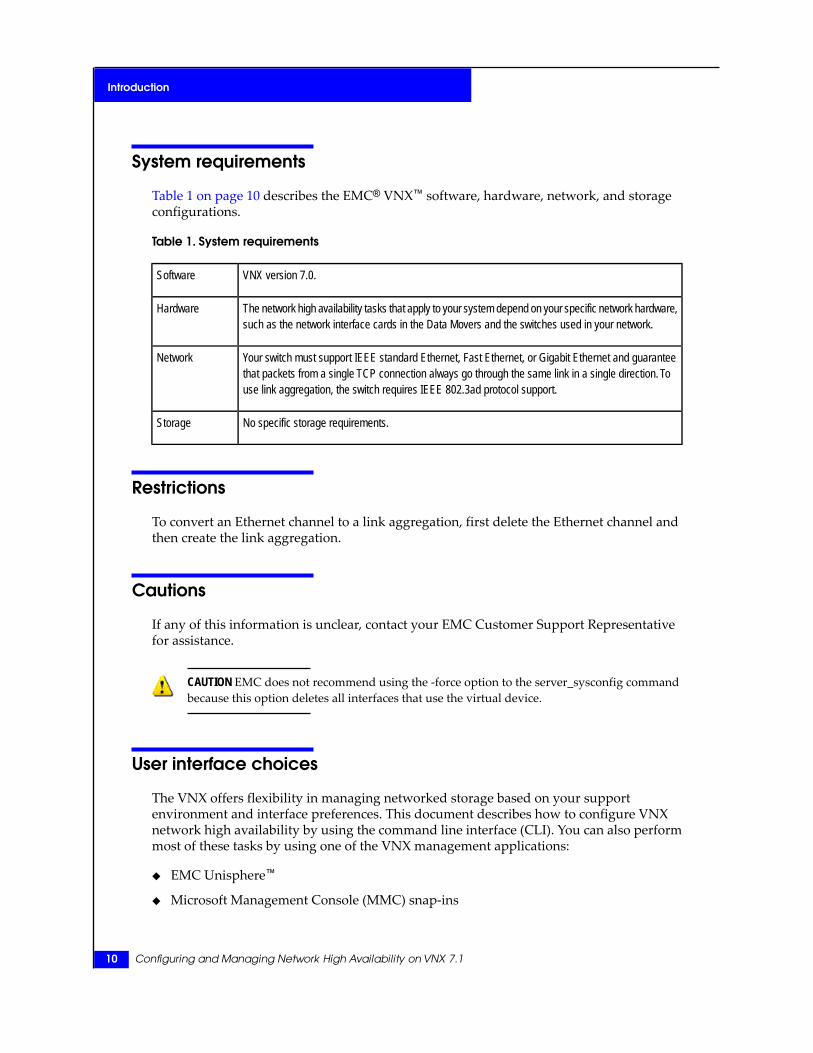
Table 1 on page 10 describes the EMC® VNX™ software, hardware, network, and storageconfigurations.
Table 1. System requirements
VNX version 7.0.Software
The network high availability tasks that apply to your system depend on your specific network hardware,such as the network interface cards in the Data Movers and the switches used in your network.
Hardware
Your switch must support IEEE standard Ethernet, Fast Ethernet, or Gigabit Ethernet and guaranteethat packets from a single TCP connection always go through the same link in a single direction. Touse link aggregation, the switch requires IEEE 802.3ad protocol support.
Network
No specific storage requirements.Storage
Restrictions
To convert an Ethernet channel to a link aggregation, first delete the Ethernet channel andthen create the link aggregation.
Cautions
If any of this information is unclear, contact your EMC Customer Support Representativefor assistance.
CAUTION EMC does not recommend using the -force option to the server_sysconfig commandbecause this option deletes all interfaces that use the virtual device.
User interface choices
The VNX offers flexibility in managing networked storage based on your supportenvironment and interface preferences. This document describes how to configure VNXnetwork high availability by using the command line interface (CLI). You can also performmost of these tasks by using one of the VNX management applications:
◆ EMC Unisphere™
◆ Microsoft Management Console (MMC) snap-ins
10 Configuring and Managing Network High Availability on VNX 7.1
Introduction

◆ Active Directory Users and Computers (ADUC) extensions
The following documents provide additional information about managing your VNX:
◆ Unisphere online help
◆ Application’s online help system in the VNX Documentation on EMC Online Support
Installing Management Applications on VNX for File includes instructions on launchingUnisphere, and on installing the MMC snap-ins and the ADUC extensions.
Related information
Specific information related to the features and functionality described in this document isincluded in:
◆ Configuring and Managing Networking on VNX
◆ EMC VNX Command Line Interface Reference for File
◆ Parameters Guide for VNX
◆ VNX for File man pages
Related information 11
Introduction

12 Configuring and Managing Network High Availability on VNX 7.1
Introduction
2
Concepts
The VNX provides network high availability or redundancy by using threetypes of virtual devices that deal with the problem of link or switch failure:
◆ FSNs that extend link failover out into the network by providingswitch-level redundancy.
◆ Ethernet channels that enable multiple active Ethernet connections tothe same switch to appear as a single link.
◆ Link aggregation that allows Ethernet ports with similar characteristicsto the same switch to be combined into a single virtual device or link.
Topics included are:◆ Virtual devices on page 14◆ Ethernet channels on page 14◆ Link aggregation on page 15◆ Switch characteristics of trunking devices on page 16◆ Statistical load balancing on page 16◆ Comparison of Ethernet channel and link aggregation on page 16◆ Fail-Safe Networks on page 17
Configuring and Managing Network High Availability on VNX 7.1 13
Virtual devices
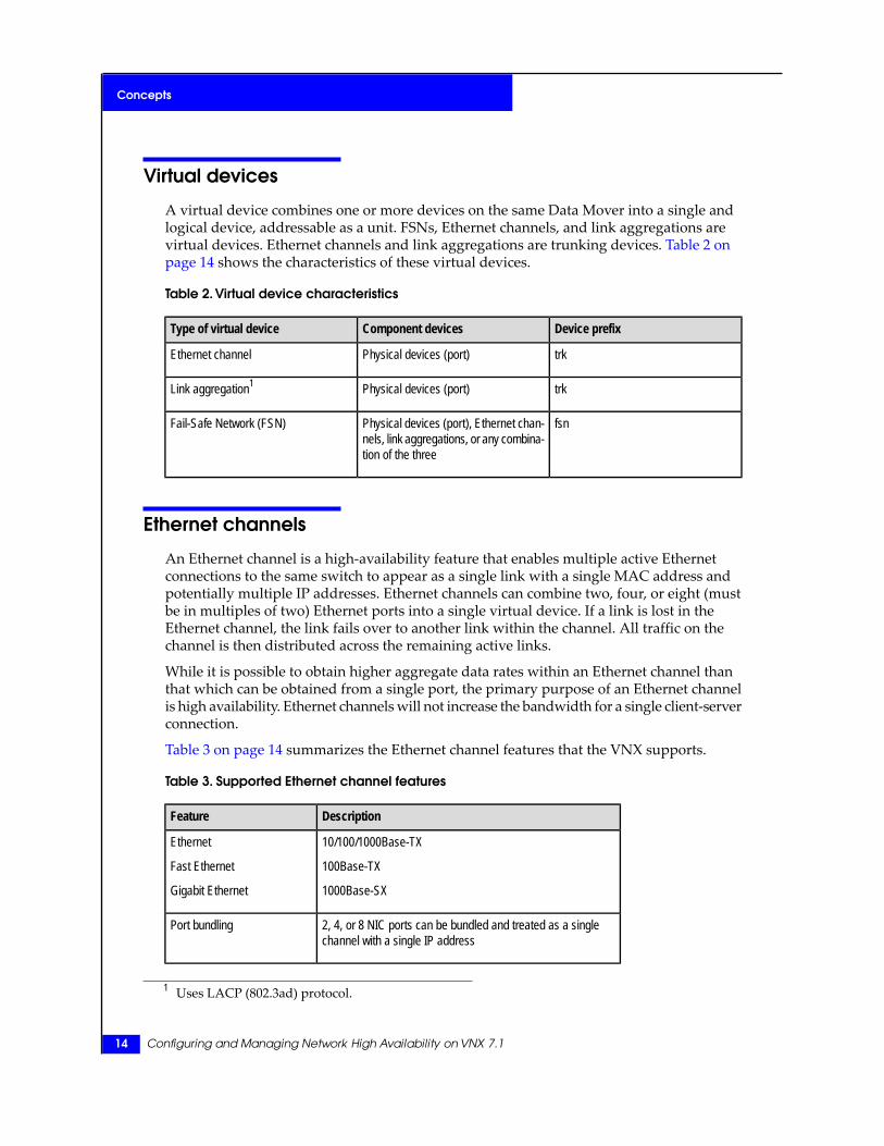
A virtual device combines one or more devices on the same Data Mover into a single andlogical device, addressable as a unit. FSNs, Ethernet channels, and link aggregations arevirtual devices. Ethernet channels and link aggregations are trunking devices. Table 2 onpage 14 shows the characteristics of these virtual devices.
Table 2. Virtual device characteristics
Device prefixComponent devicesType of virtual device
trkPhysical devices (port)Ethernet channel
trkPhysical devices (port)Link aggregation1
fsnPhysical devices (port), Ethernet chan-nels, link aggregations, or any combina-tion of the three
Fail-Safe Network (FSN)
Ethernet channels
An Ethernet channel is a high-availability feature that enables multiple active Ethernetconnections to the same switch to appear as a single link with a single MAC address andpotentially multiple IP addresses. Ethernet channels can combine two, four, or eight (mustbe in multiples of two) Ethernet ports into a single virtual device. If a link is lost in theEthernet channel, the link fails over to another link within the channel. All traffic on thechannel is then distributed across the remaining active links.
While it is possible to obtain higher aggregate data rates within an Ethernet channel thanthat which can be obtained from a single port, the primary purpose of an Ethernet channelis high availability. Ethernet channels will not increase the bandwidth for a single client-serverconnection.
Table 3 on page 14 summarizes the Ethernet channel features that the VNX supports.
Table 3. Supported Ethernet channel features
DescriptionFeature
10/100/1000Base-TX
100Base-TX
1000Base-SX
Ethernet
Fast Ethernet
Gigabit Ethernet
2, 4, or 8 NIC ports can be bundled and treated as a singlechannel with a single IP address
Port bundling
1 Uses LACP (802.3ad) protocol.
14 Configuring and Managing Network High Availability on VNX 7.1
Concepts
Table 3. Supported Ethernet channel features (continued)
DescriptionFeature
Complies with the IP standardInternet Protocol (IP) support
Link aggregation
A link aggregation resembles an Ethernet channel, but uses the Link Aggregation ControlProtocol (LACP) IEEE 802.3ad standard. The major goals of the LACP are as follows:
◆ Flexible configuration — Unlike Ethernet channels, the number of links in a linkaggregation is need not be a multiple of two. It can be any number greater than one, upto a maximum of 12.
◆ Increased availability — The loss of a link within an aggregation reduces the overallbandwidth, but data flow is uninterrupted. LACP monitors the health of each link andcan detect types of failures unlike an Ethernet channel.
◆ Link control configuration — The protocol identifies wrongly connected links, marksthem as down, and uses only correctly configured links.
◆ Deterministic behavior — The protocol has several state machines for each link, ensuringdeterministic behavior.
◆ Transparency — The aggregation appears to be another Ethernet link.◆ Industry standard — Link aggregation is defined by the IEEE 802.3ad standard.
The IEEE 802.3ad standard supports link aggregation with one or more ports. If theaggregation uses one port, then the port should be full duplex. If the aggregation uses morethan one port, all the ports must have the same speed and be full duplex. If a link with adifferent speed or a half-duplex link is configured into an aggregated link, it is not allowedto participate in the aggregation. Instead, it is marked as down and not used. For example,if one link is 100 megabits per second and the other three links are 10 megabits per second,the 100 megabits per second link is marked as down. In this case, the link aggregation usesthe larger number of slower links. Because the goal of link aggregation is availability, ratherthan increased bandwidth, the protocol uses the largest number of links with a commonspeed rather than the links with the fastest speed.
Note: The VNX does not reject establishing an aggregated link that includes ports from both FastEthernet and Gigabit Ethernet cards or a combination of copper and optical ports. It configures theaggregated link, but allows only the majority of links of whichever type to participate in the aggregation.
Although link aggregations provide more overall bandwidth than a single port, theconnection to any single client runs through one physical port and is therefore limited bythe port’s bandwidth. If the connection to one port fails, the switch automatically switchestraffic to the remaining ports, when applicable. When the connection is restored, the switchautomatically resumes by using the port as part of the aggregated link.
Link aggregation 15
Concepts
Switch characteristics of trunking devices
To use Ethernet channels and link aggregations, a complimentary configuration on theswitch is required. The switch must support:
◆ IEEE standard Ethernet, Fast Ethernet, or Gigabit Ethernet◆ IEEE 802.3ad Link Aggregation protocol
Ensure that the switch’s trunking implementation guarantees packets from a single TCPconnection that always go through the same link in a single direction. Switches might supporta number of switching algorithms, that includes IP, TCP, and MAC. Out-of-order packetdelivery in a single direction is prevented because of the deterministic nature of framedistribution within switches.
The VNX determines outgoing traffic, while the switch determines incoming traffic. Therefore,neither incoming nor outgoing traffic need to be on the same link.
Note: Consult the documentation accompanying your switch to determine the device’s configurationrequirements and whether your model supports Ethernet channels and link aggregations. For example,the Ethernet channel implemented in the VNX works in conjunction with the EtherChannel paradigmdeveloped by Cisco Systems. The VNX requires statically configured EtherChannels and does notsupport the Port Aggregation Protocol (PAgP) from Cisco Systems.
Statistical load balancing
The VNX uses load balancing to distribute frames across links in Ethernet channels andaggregated links. Load balancing works by using a portion of the source and destinationMAC addresses to select one of the links. If the same source and destination addresses areused, the same link within the channel or aggregated link is used.
You can configure statistical load balancing by using IP addresses, TCP ports and IPaddresses, or MAC addresses. The default method of load balancing is by using IP addresses.
Comparison of Ethernet channel and link aggregation
The information in Table 4 on page 17 will help you determine when to use an Ethernetchannel or link aggregation.
16 Configuring and Managing Network High Availability on VNX 7.1
Concepts
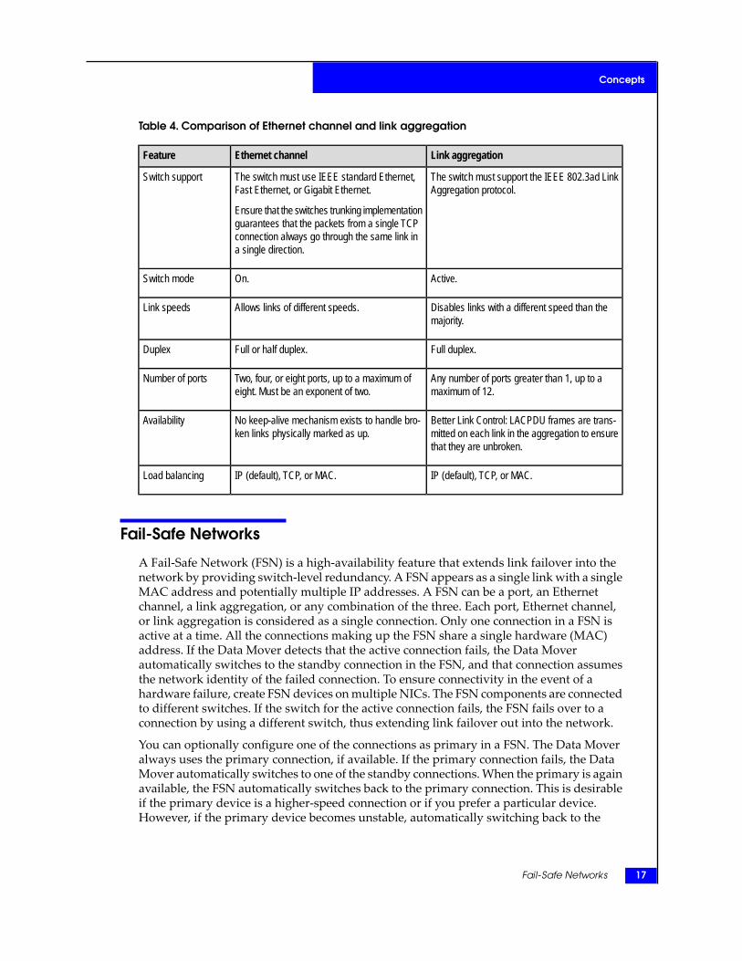
Table 4. Comparison of Ethernet channel and link aggregation
Link aggregationEthernet channelFeature
The switch must support the IEEE 802.3ad LinkAggregation protocol.
The switch must use IEEE standard Ethernet,Fast Ethernet, or Gigabit Ethernet.
Ensure that the switches trunking implementationguarantees that the packets from a single TCPconnection always go through the same link ina single direction.
Switch support
Active.On.Switch mode
Disables links with a different speed than themajority.
Allows links of different speeds.Link speeds
Full duplex.Full or half duplex.Duplex
Any number of ports greater than 1, up to amaximum of 12.
Two, four, or eight ports, up to a maximum ofeight. Must be an exponent of two.
Number of ports
Better Link Control: LACPDU frames are trans-mitted on each link in the aggregation to ensurethat they are unbroken.
No keep-alive mechanism exists to handle bro-ken links physically marked as up.
Availability
IP (default), TCP, or MAC.IP (default), TCP, or MAC.Load balancing
Fail-Safe Networks
A Fail-Safe Network (FSN) is a high-availability feature that extends link failover into thenetwork by providing switch-level redundancy. A FSN appears as a single link with a singleMAC address and potentially multiple IP addresses. A FSN can be a port, an Ethernetchannel, a link aggregation, or any combination of the three. Each port, Ethernet channel,or link aggregation is considered as a single connection. Only one connection in a FSN isactive at a time. All the connections making up the FSN share a single hardware (MAC)address. If the Data Mover detects that the active connection fails, the Data Moverautomatically switches to the standby connection in the FSN, and that connection assumesthe network identity of the failed connection. To ensure connectivity in the event of ahardware failure, create FSN devices on multiple NICs. The FSN components are connectedto different switches. If the switch for the active connection fails, the FSN fails over to aconnection by using a different switch, thus extending link failover out into the network.
You can optionally configure one of the connections as primary in a FSN. The Data Moveralways uses the primary connection, if available. If the primary connection fails, the DataMover automatically switches to one of the standby connections. When the primary is againavailable, the FSN automatically switches back to the primary connection. This is desirableif the primary device is a higher-speed connection or if you prefer a particular device.However, if the primary device becomes unstable, automatically switching back to the
Fail-Safe Networks 17
Concepts
primary device might cause the FSN to toggle between the primary device and the standbydevice.
The Data Mover uses the next standby connection if you do not configure a primaryconnection. If the active connection fails, the Data Mover switches to the standby connectionand continues to use that connection until it fails.
There is no requirement that the connections making up a FSN be the same type, or that theconnections be made to the same network switch. For example, a FSN might have a singleGigabit Ethernet port and an Ethernet channel made up of four 100-megabit Ethernet ports.
If a FSN uses an Ethernet channel or link aggregation as a connection, the FSN fails overonly when the entire channel or aggregation fails. For example, if one port in a four-portEthernet channel fails, the switch redirects traffic to the remaining three ports. From theData Mover’s perspective, the channel is still available, so the FSN does not fail over toanother connection.
Note: If you want to include either Ethernet channels or link aggregations in FSN devices, configurethem before creating the FSN.
Unlike Ethernet channels and link aggregations, FSNs can maintain full bandwidth duringa failover.
When the Data Mover detects the loss of the active communications link to the FSN, theconnection automatically fails over to an operational standby component of the FSN device.This action is independent of any channel or switch features. If a link within the FSN devicegoes down, the link fails over to a surviving link, if any, specified in the FSN configuration.
FSN examples
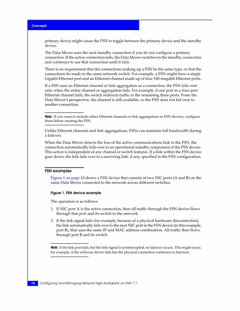
Figure 1 on page 18 shows a FSN device that consists of two NIC ports (A and B) on thesame Data Mover connected to the network across different switches.
Figure 1. FSN device example
The operation is as follows:
1. If NIC port A is the active connection, then all traffic through the FSN device flowsthrough that port and its switch to the network.
2. If the link signal fails (for example, because of a physical hardware disconnection),the link automatically fails over to the next NIC port in the FSN device (in this example,port B), that uses the same IP and MAC address combination. All traffic then flowsthrough port B and its switch.
Note: If the link port fails, but the link signal is uninterrupted, no failover occurs. This might occur,for example, if the software driver fails but the physical connection continues to function.
18 Configuring and Managing Network High Availability on VNX 7.1
Concepts
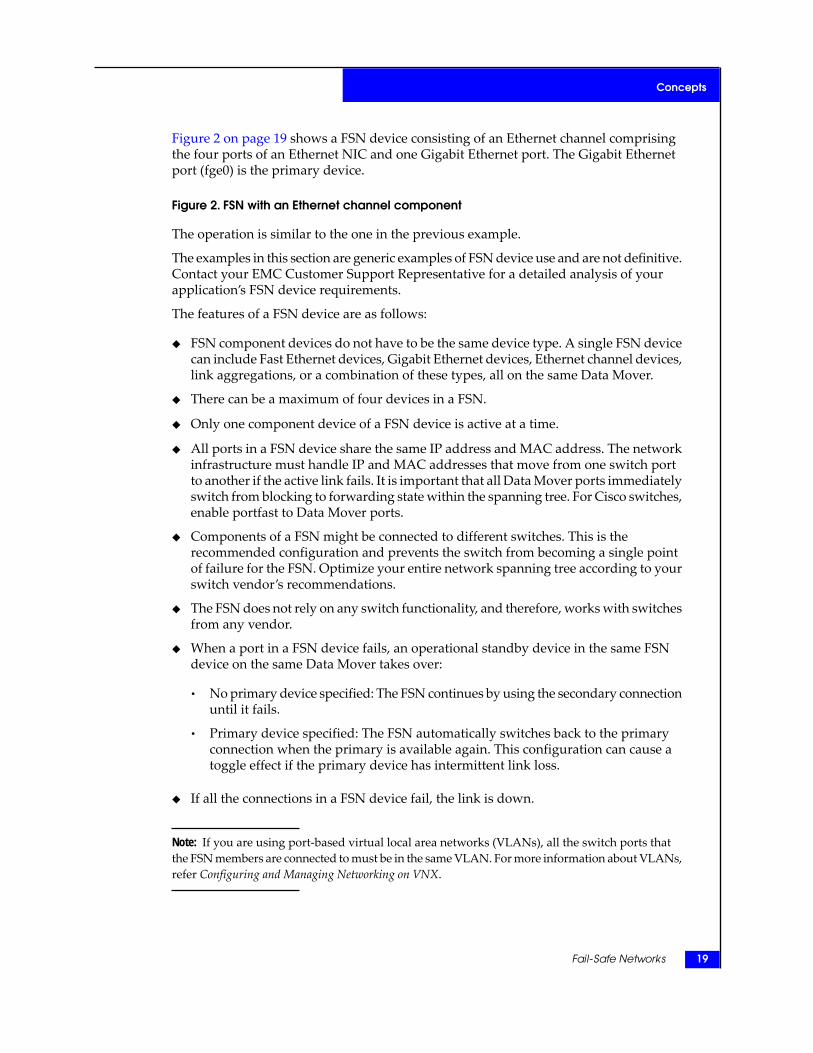
Figure 2 on page 19 shows a FSN device consisting of an Ethernet channel comprisingthe four ports of an Ethernet NIC and one Gigabit Ethernet port. The Gigabit Ethernetport (fge0) is the primary device.
Figure 2. FSN with an Ethernet channel component
The operation is similar to the one in the previous example.
The examples in this section are generic examples of FSN device use and are not definitive.Contact your EMC Customer Support Representative for a detailed analysis of yourapplication’s FSN device requirements.
The features of a FSN device are as follows:
◆ FSN component devices do not have to be the same device type. A single FSN devicecan include Fast Ethernet devices, Gigabit Ethernet devices, Ethernet channel devices,link aggregations, or a combination of these types, all on the same Data Mover.
◆ There can be a maximum of four devices in a FSN.
◆ Only one component device of a FSN device is active at a time.
◆ All ports in a FSN device share the same IP address and MAC address. The networkinfrastructure must handle IP and MAC addresses that move from one switch portto another if the active link fails. It is important that all Data Mover ports immediatelyswitch from blocking to forwarding state within the spanning tree. For Cisco switches,enable portfast to Data Mover ports.
◆ Components of a FSN might be connected to different switches. This is therecommended configuration and prevents the switch from becoming a single pointof failure for the FSN. Optimize your entire network spanning tree according to yourswitch vendor’s recommendations.
◆ The FSN does not rely on any switch functionality, and therefore, works with switchesfrom any vendor.
◆ When a port in a FSN device fails, an operational standby device in the same FSNdevice on the same Data Mover takes over:
• No primary device specified: The FSN continues by using the secondary connectionuntil it fails.
• Primary device specified: The FSN automatically switches back to the primaryconnection when the primary is available again. This configuration can cause atoggle effect if the primary device has intermittent link loss.
◆ If all the connections in a FSN device fail, the link is down.
Note: If you are using port-based virtual local area networks (VLANs), all the switch ports thatthe FSN members are connected to must be in the same VLAN. For more information about VLANs,refer Configuring and Managing Networking on VNX.
Fail-Safe Networks 19
Concepts
20 Configuring and Managing Network High Availability on VNX 7.1
Concepts

3
Configuring
The tasks to configure network high availability are:◆ Configure an Ethernet channel on page 22◆ Configure link aggregation on page 27◆ Configure a FSN device on page 31
Configuring and Managing Network High Availability on VNX 7.1 21
Configure an Ethernet channel
If you plan to use an Ethernet channel in a FSN device, do not configure IP addresses forthe Ethernet channel here. Doing so makes those interfaces unavailable for use in the FSNdevice and results in an error message when trying to configure them as part of a FSN device.Assign the IP addresses to the FSN device later when you configure the FSN device.
Configure an Ethernet channel with two Ethernet ports — Example 1
1. Configure the switches in your network to support Ethernet channels. The documentationprovided with your switch provides the proper procedure to configure the switches.
Note: Configure the same mode (set to on) for all ports in the Ethernet channel on the switch.Configuring the ports with different Ethernet channel modes may produce unpredictable results.
2. Ensure that the physical devices to be combined into the Ethernet channel match thespeed and duplex settings of the switch. View the speed and duplex settings of the deviceson the Data Mover by using this command syntax:
$ server_sysconfig <movername> -pci
where:
<movername> = name of the Data Mover on which you plan to configure the Ethernetchannel
Compare the information displayed by this command to the settings on your switch orrouter.
Note: Typically, all the physical devices in a channel use the same speed and duplex settings, butif the switch allows a mixture of these settings, the channel must match the requirements of theswitch.
Example:
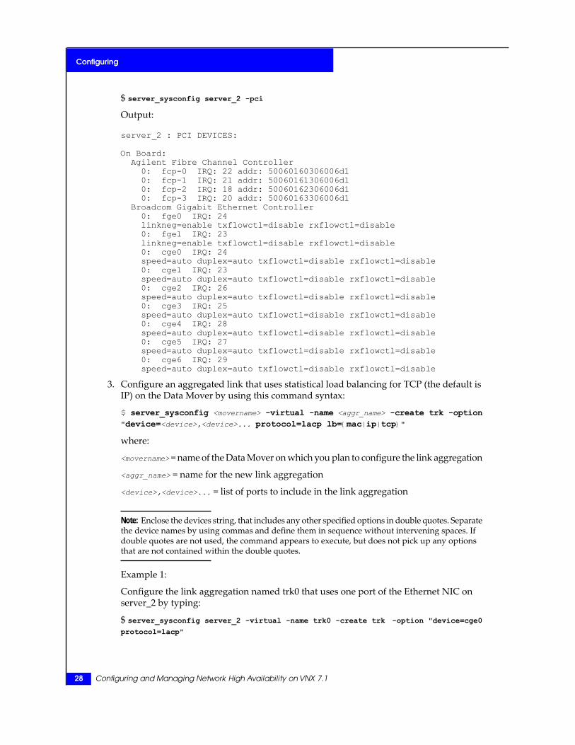
$ server_sysconfig server_2 -pci
Output:
22 Configuring and Managing Network High Availability on VNX 7.1
Configuring
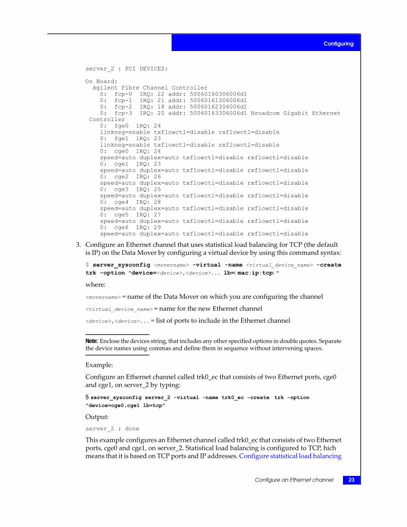
server_2 : PCI DEVICES:
On Board:Agilent Fibre Channel Controller0: fcp-0 IRQ: 22 addr: 50060160306006d10: fcp-1 IRQ: 21 addr: 50060161306006d10: fcp-2 IRQ: 18 addr: 50060162306006d10: fcp-3 IRQ: 20 addr: 50060163306006d1 Broadcom Gigabit Ethernet
Controller0: fge0 IRQ: 24linkneg=enable txflowctl=disable rxflowctl=disable0: fge1 IRQ: 23linkneg=enable txflowctl=disable rxflowctl=disable0: cge0 IRQ: 24speed=auto duplex=auto txflowctl=disable rxflowctl=disable0: cge1 IRQ: 23speed=auto duplex=auto txflowctl=disable rxflowctl=disable0: cge2 IRQ: 26speed=auto duplex=auto txflowctl=disable rxflowctl=disable0: cge3 IRQ: 25speed=auto duplex=auto txflowctl=disable rxflowctl=disable0: cge4 IRQ: 28speed=auto duplex=auto txflowctl=disable rxflowctl=disable0: cge5 IRQ: 27speed=auto duplex=auto txflowctl=disable rxflowctl=disable0: cge6 IRQ: 29speed=auto duplex=auto txflowctl=disable rxflowctl=disable
3. Configure an Ethernet channel that uses statistical load balancing for TCP (the defaultis IP) on the Data Mover by configuring a virtual device by using this command syntax:
$ server_sysconfig <movername> -virtual -name <virtual_device_name> -createtrk -option "device=<device>,<device>... lb={mac|ip|tcp}"
where:
<movername> = name of the Data Mover on which you are configuring the channel
<virtual_device_name> = name for the new Ethernet channel
<device>,<device>... = list of ports to include in the Ethernet channel
Note: Enclose the devices string, that includes any other specified options in double quotes. Separatethe device names using commas and define them in sequence without intervening spaces.
Example:
Configure an Ethernet channel called trk0_ec that consists of two Ethernet ports, cge0and cge1, on server_2 by typing:
$ server_sysconfig server_2 -virtual -name trk0_ec -create trk -option
"device=cge0,cge1 lb=tcp"
Output:
server_2 : done
This example configures an Ethernet channel called trk0_ec that consists of two Ethernetports, cge0 and cge1, on server_2. Statistical load balancing is configured to TCP, hichmeans that it is based on TCP ports and IP addresses. Configure statistical load balancing
Configure an Ethernet channel 23
Configuring
on a Data Mover on page 43 provides information about configuring load balancing ona Data Mover.
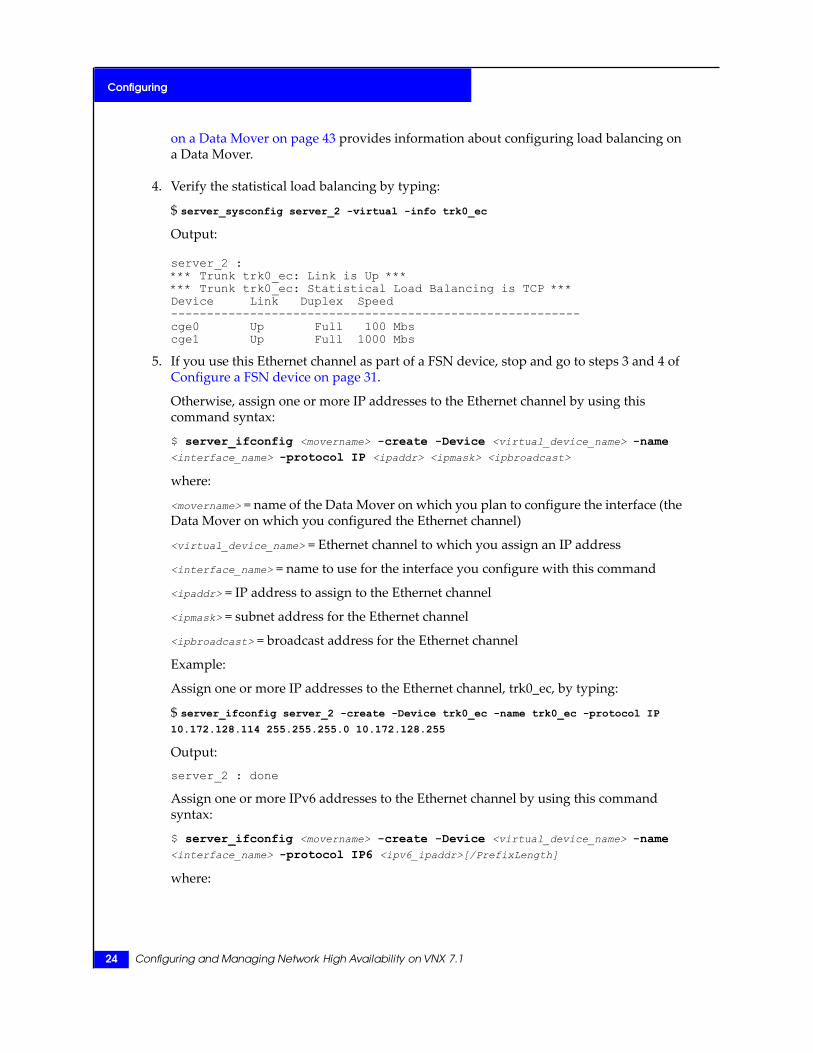
4. Verify the statistical load balancing by typing:
$ server_sysconfig server_2 -virtual -info trk0_ec
Output:
server_2 :*** Trunk trk0_ec: Link is Up ****** Trunk trk0_ec: Statistical Load Balancing is TCP ***Device Link Duplex Speed---------------------------------------------------------cge0 Up Full 100 Mbscge1 Up Full 1000 Mbs
5. If you use this Ethernet channel as part of a FSN device, stop and go to steps 3 and 4 ofConfigure a FSN device on page 31.
Otherwise, assign one or more IP addresses to the Ethernet channel by using thiscommand syntax:
$ server_ifconfig <movername> -create -Device <virtual_device_name> -name<interface_name> -protocol IP <ipaddr> <ipmask> <ipbroadcast>
where:
<movername> = name of the Data Mover on which you plan to configure the interface (theData Mover on which you configured the Ethernet channel)
<virtual_device_name> = Ethernet channel to which you assign an IP address
<interface_name> = name to use for the interface you configure with this command
<ipaddr> = IP address to assign to the Ethernet channel
<ipmask> = subnet address for the Ethernet channel
<ipbroadcast> = broadcast address for the Ethernet channel
Example:
Assign one or more IP addresses to the Ethernet channel, trk0_ec, by typing:
$ server_ifconfig server_2 -create -Device trk0_ec -name trk0_ec -protocol IP
10.172.128.114 255.255.255.0 10.172.128.255
Output:
server_2 : done
Assign one or more IPv6 addresses to the Ethernet channel by using this commandsyntax:
$ server_ifconfig <movername> -create -Device <virtual_device_name> -name<interface_name> -protocol IP6 <ipv6_ipaddr>[/PrefixLength]
where:
24 Configuring and Managing Network High Availability on VNX 7.1
Configuring

<movername> = name of the Data Mover on which you plan to configure the interface (theData Mover on which you configured the aggregated link)
<virtual_device_name> = aggregated link to which you assign an IPv6 address
<interface_name> = name to use for the interface you configure with this command
<ipv6_addr> = IPv6 address to assign to the aggregated link
[/PrefixLength] = prefix length of the IPv6 address. When prefix length is not specified,the default value of 64 is used.
Example:
Assign one or more IPv6 addresses to the Ethernet channel, trk0_ec, by typing:
$ server_ifconfig server_2 -create -Device trk0_ec -name trk0_ec -protocol IP6
2620:0:170:6973:6e75:6d62:6572:1
Output:
server_2 : done
6. Verify the IP addresses assigned to the Ethernet channel by typing:
$ server_ifconfig server_2 trk0_ec
Output:
server_2 :trk0_ec protocol=IP device=trk0_ecinet=10.172.128.114 netmask=255.255.255.0
broadcast=10.172.128.255UP, ethernet, mtu=1500, vlan=0, macaddr=0:60:16:4:33:14
Verify the IPv6 addresses assigned to the Ethernet channel by typing:
$ server_ifconfig server_2 trk0_ec
Output:
server_2 :trk0_ec protocol=IP6 device=trk0_ecinet=2620:0:170:6973:6e75:6d62:6572:1 prefix=64UP, ethernet, mtu=1500, vlan=0, macaddr=0:60:16:4:33:14
Ethernet channel examples
Table 5 on page 25 shows the server_sysconfig commands used to configure an Ethernetchannel on a Data Mover. These examples use the default NIC interface names. If youmodified the interface names in your configuration, modify these commands accordingly.
Table 5. Ethernet channel examples
CommandNIC type
server_sysconfig server_2 -virtual -n trk0_ec-createtrk -option "device=ana0,ana1,ana2,ana3"
Fast Ethernet, singleNIC (4-port)
Configure an Ethernet channel 25
Configuring
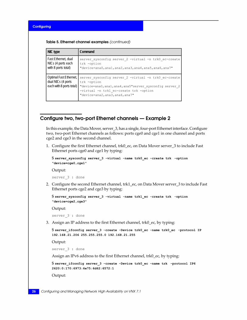
Table 5. Ethernet channel examples (continued)
CommandNIC type
server_sysconfig server_2 -virtual -n trk0_ec-createtrk -option"device=ana0,ana1,ana2,ana3,ana4,ana5,ana6,ana7"
Fast Ethernet, dualNICs (4 ports eachwith 8 ports total)
server_sysconfig server_2 -virtual -n trk0_ec-createtrk -option
Optimal Fast Ethernet,dual NICs (4 portseach with 8 ports total) "device=ana0,ana1,ana4,ana5"server_sysconfig server_2
-virtual -n trk1_ec-create trk -option"device=ana2,ana3,ana6,ana7"
Configure two, two-port Ethernet channels — Example 2
In this example, the Data Mover, server_3, has a single, four-port Ethernet interface. Configuretwo, two-port Ethernet channels as follows: ports cge0 and cge1 in one channel and portscge2 and cge3 in the second channel.
1. Configure the first Ethernet channel, trk0_ec, on Data Mover server_3 to include FastEthernet ports cge0 and cge1 by typing:
$ server_sysconfig server_3 -virtual -name trk0_ec -create trk -option
"device=cge0,cge1"
Output:
server_3 : done
2. Configure the second Ethernet channel, trk1_ec, on Data Mover server_3 to include FastEthernet ports cge2 and cge3 by typing:
$ server_sysconfig server_3 -virtual -name trk1_ec -create trk -option
"device=cge2,cge3"
Output:
server_3 : done
3. Assign an IP address to the first Ethernet channel, trk0_ec, by typing:
$ server_ifconfig server_3 -create -Device trk0_ec -name trk0_ec -protocol IP
192.168.21.206 255.255.255.0 192.168.21.255
Output:
server_3 : done
Assign an IPv6 address to the first Ethernet channel, trk0_ec, by typing:
$ server_ifconfig server_3 -create -Device trk0_ec -name trk -protocol IP6
2620:0:170:6973:6e75:6d62:6572:1
Output:
26 Configuring and Managing Network High Availability on VNX 7.1
Configuring

server_3 : done
4. Assign an IP address to the second Ethernet channel, trk1_ec, by typing:
$ server_ifconfig server_3 -create -Device trk1_ec -name trk1_ec -protocol IP
192.168.21.207 255.255.255.0 192.168.21.255
Output:
server_3 : done
Assign an IPv6 address to the first Ethernet channel, trk1_ec, by typing:
$ server_ifconfig server_3 -create -Device trk1_ec -name trk -protocol IP6
2720:100:001:001:a:b:c:d/64
Output:
server_3 : done
Configure link aggregation
If you plan to use link aggregation in a FSN device, do not configure IP addresses for thelink aggregation here. Doing so makes those interfaces unavailable for use in the FSN deviceand results in an error message when trying to configure them as part of a FSN device.Assign the IP addresses to the FSN device later when you configure the FSN device.
1. Configure the switches in your network to support link aggregation. The switch mustsupport the link aggregation protocol, IEEE 802.3ad. Consult the documentation providedwith your switch for the proper procedure.
Note: Configure the same mode (set to active) for all ports in the link aggregation on the switch.Configuring the ports with different modes can produce unpredictable results.
EMC recommends that the peer switch is set to active mode. According to the 802.3adprotocol, active mode is the only fully compliant mode. In active mode, if there is achange, both sides can synchronize quickly. In addition, there are cases when a faultmight be discovered only when both sides are active (the Data Mover side is alwaysactive). Therefore, using passive mode might compromise high availability.
2. Verify that the physical devices to be combined into the link aggregation use the samespeed and are either full-duplex or auto (default). Also verify that the settings matchthose of the switch. View the speed and duplex settings of the devices on the Data Moverby using this command syntax:
$ server_sysconfig <movername> -pci
where:
<movername> = name of the Data Mover on which you plan to configure the link aggregation
Example:
View the speed and duplex settings of the devices on the Data Mover server_2 by typing:
Configure link aggregation 27
Configuring
$ server_sysconfig server_2 -pci
Output:
server_2 : PCI DEVICES:
On Board:Agilent Fibre Channel Controller0: fcp-0 IRQ: 22 addr: 50060160306006d10: fcp-1 IRQ: 21 addr: 50060161306006d10: fcp-2 IRQ: 18 addr: 50060162306006d10: fcp-3 IRQ: 20 addr: 50060163306006d1
Broadcom Gigabit Ethernet Controller0: fge0 IRQ: 24linkneg=enable txflowctl=disable rxflowctl=disable0: fge1 IRQ: 23linkneg=enable txflowctl=disable rxflowctl=disable0: cge0 IRQ: 24speed=auto duplex=auto txflowctl=disable rxflowctl=disable0: cge1 IRQ: 23speed=auto duplex=auto txflowctl=disable rxflowctl=disable0: cge2 IRQ: 26speed=auto duplex=auto txflowctl=disable rxflowctl=disable0: cge3 IRQ: 25speed=auto duplex=auto txflowctl=disable rxflowctl=disable0: cge4 IRQ: 28speed=auto duplex=auto txflowctl=disable rxflowctl=disable0: cge5 IRQ: 27speed=auto duplex=auto txflowctl=disable rxflowctl=disable0: cge6 IRQ: 29speed=auto duplex=auto txflowctl=disable rxflowctl=disable
3. Configure an aggregated link that uses statistical load balancing for TCP (the default isIP) on the Data Mover by using this command syntax:
$ server_sysconfig <movername> -virtual -name <aggr_name> -create trk -option"device=<device>,<device>... protocol=lacp lb={mac|ip|tcp}"
where:
<movername> = name of the Data Mover on which you plan to configure the link aggregation
<aggr_name> = name for the new link aggregation
<device>,<device>... = list of ports to include in the link aggregation
Note: Enclose the devices string, that includes any other specified options in double quotes. Separatethe device names by using commas and define them in sequence without intervening spaces. Ifdouble quotes are not used, the command appears to execute, but does not pick up any optionsthat are not contained within the double quotes.
Example 1:
Configure the link aggregation named trk0 that uses one port of the Ethernet NIC onserver_2 by typing:
$ server_sysconfig server_2 -virtual -name trk0 -create trk -option "device=cge0
protocol=lacp"
28 Configuring and Managing Network High Availability on VNX 7.1
Configuring

Output:
server_2 : done
In example 1, only one port of the Ethernet NIC on server_2 forms the link aggregationnamed trk0.
Example 2:
Configure the link aggregation named trk0_la that uses the three ports of the EthernetNIC on server_2 by typing:
$ server_sysconfig server_2 -virtual -name trk0_la -create trk -option
"device=cge2,cge3,cge4 protocol=lacp lb=tcp"
Output:
server_2 : done
In example 2, three ports of the Ethernet NIC on server_2 are included in the linkaggregation named trk0_la and statistical load balancing is configured to TCP.
Configure statistical load balancing on a Data Mover on page 43 provides informationabout configuring load balancing on a Data Mover.
4. Verify the statistical load balancing, for example 2, by typing:
$ server_sysconfig server_2 -virtual -info trk0_la
Output:
server_2 :*** Trunk trk0_la: Link is Up ****** Trunk trk0_la: Timeout is Short ****** Trunk trk0_la: Statistical Load Balancing is TCP ***Device Local Grp Remote Grp Link LACP Duplex Speed----------------------------------------------------------------cge2 10000 6400 Up Up Full 1000 Mbscge3 10000 6400 Up Up Full 1000 Mbscge4 10000 6400 Up Up Full 1000 Mbs
5. To use this link aggregation as part of a FSN device, stop and go to steps 3 and 4 ofConfigure a FSN device on page 31.
Assign one or more IP addresses to the link aggregation by using this command syntax:
$ server_ifconfig <movername> -create -Device <virtual_device_name> -name<interface_name> -protocol IP <ipaddr> <ipmask> <ipbroadcast>
where:
<movername> = name of the Data Mover on which you plan to configure the interface (theData Mover on which you configured the aggregated link)
<virtual_device_name> = aggregated link to which you assign an IP address
<interface_name> = name to use for the interface you configure with this command
<ipaddr> = IP address to assign to the aggregated link
<ipmask> = subnet address for the aggregated link
Configure link aggregation 29
Configuring

<ipbroadcast> = broadcast address for the aggregated link
Example:
Assign one or more IP addresses to the link aggregation by typing:
$ server_ifconfig server_2 -create -Device trk0_la -name trk0_la-protocol IP
10.172.128.116 255.255.255.0 10.172.128.255
Output:
server_2 : done
Assign one or more IPv6 addresses to the link aggregation by using this command syntax:
$ server_ifconfig <movername> -create -Device <virtual_device_name> -name<interface_name> -protocol IP6 <ipv6_ipaddr>[/PrefixLength]
where:
<movername> = name of the Data Mover on which you plan to configure the interface (theData Mover on which you configured the aggregated link)
<virtual_device_name> = aggregated link to which you assign an IPv6 address
Assign one or more IPv6 addresses to the link aggregation by using this command syntax:
<interface_name> = name to use for the interface you configure with this command
<ipv6_addr> = IPv6 address to assign to the aggregated link
[/PrefixLength] = prefix length of the IPv6 address. When prefix length is not specified,the default value of 64 is used.
Example:
Assign one or more IPv6 addresses to the link aggregation by typing:
$ server_ifconfig server_2 -create -Device trk0_la -name trk0_la -protocol IP6
2620:0:170:6973:6e75:6d62:6572:1
Output:
server_2 : done
6. Verify the IP addresses assigned to the link aggregation by typing:
$ server_ifconfig server_2 trk0_la
Output:
server_2 :trk0_la protocol=IP device=trk0_lainet=10.172.128.116 netmask=255.255.255.0broadcast=10.172.128.255
UP, ethernet, mtu=1500, vlan=0, macaddr=0:60:16:4:35:2f
Verify the IPv6 addresses assigned to the link aggregation by typing:
$ server_ifconfig server_2 trk0_la
Output:
30 Configuring and Managing Network High Availability on VNX 7.1
Configuring

server_2 :trk0_la protocol=IP6 device=trk0_lainet=2620:0:170:6973:6e75:6d62:6572:1 prefix=64UP, ethernet, mtu=1500, vlan=0, macaddr=0:60:16:4:35:2f
Configure a FSN device
A FSN can be a port, an Ethernet channel, a link aggregation, or any combination of thethree.
Configure a FSN using Ethernet ports — Example 1
1. Configure the switches in your network to support the Data Mover connections. Youcan connect the devices that constitute the FSN device to different switches. Consult thedocumentation provided with your switch for the proper procedure.
FSN adds no additional requirements to those of the component devices. For example,a single port configured in a FSN is configured at the switch in the same way as a singleport unused in a FSN.
2. Include any Ethernet channels or link aggregations in the FSN by configuring them firstusing the procedure in Configure an Ethernet channel on page 22 or Configure linkaggregation on page 27.
Note: Do not configure IP addresses for interfaces on the devices to be included in the FSN deviceprior to configuring the virtual device. This makes those interfaces unavailable for use in the FSNdevice and results in an error message when you try to configure them as part of a FSN device.
3. Configure the FSN device by using this command syntax:
$ server_sysconfig <movername> -virtual -name <fsn_device_name> -create fsn-option "[primary=<primary_device>] device=<device>,<standby_device>... [,...]"
Note: Enclose the devices string, that includes any other specified options in double quotes. Separatethe device names by using commas and define them in sequence with no intervening spaces.
where:
<movername> = name of the Data Mover on which to configure the FSN
<fsn_devicename> = name of the new FSN device
<primary_device> = name of the primary device
<standby_device>,... = list of devices to use as standby devices
Note: Do not use "fsn" as the <fsn_device_name>; it is a restricted name.
Configure a FSN device 31
Configuring
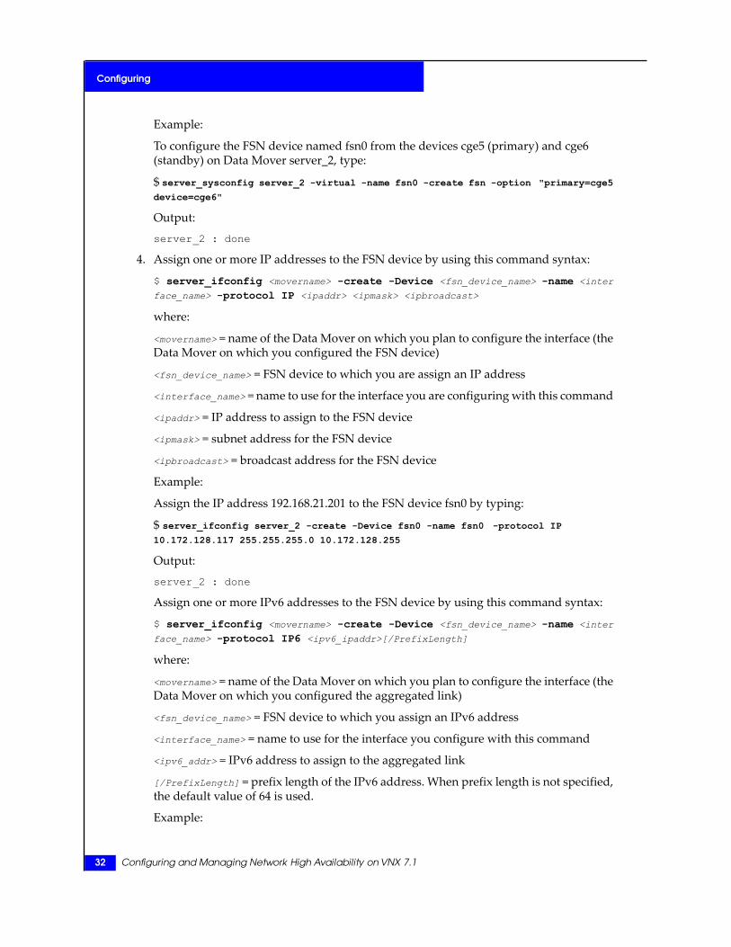
Example:
To configure the FSN device named fsn0 from the devices cge5 (primary) and cge6(standby) on Data Mover server_2, type:
$ server_sysconfig server_2 -virtual -name fsn0 -create fsn -option "primary=cge5
device=cge6"
Output:
server_2 : done
4. Assign one or more IP addresses to the FSN device by using this command syntax:
$ server_ifconfig <movername> -create -Device <fsn_device_name> -name <inter
face_name> -protocol IP <ipaddr> <ipmask> <ipbroadcast>
where:
<movername> = name of the Data Mover on which you plan to configure the interface (theData Mover on which you configured the FSN device)
<fsn_device_name> = FSN device to which you are assign an IP address
<interface_name> = name to use for the interface you are configuring with this command
<ipaddr> = IP address to assign to the FSN device
<ipmask> = subnet address for the FSN device
<ipbroadcast> = broadcast address for the FSN device
Example:
Assign the IP address 192.168.21.201 to the FSN device fsn0 by typing:
$ server_ifconfig server_2 -create -Device fsn0 -name fsn0 -protocol IP
10.172.128.117 255.255.255.0 10.172.128.255
Output:
server_2 : done
Assign one or more IPv6 addresses to the FSN device by using this command syntax:
$ server_ifconfig <movername> -create -Device <fsn_device_name> -name <inter
face_name> -protocol IP6 <ipv6_ipaddr>[/PrefixLength]
where:
<movername> = name of the Data Mover on which you plan to configure the interface (theData Mover on which you configured the aggregated link)
<fsn_device_name> = FSN device to which you assign an IPv6 address
<interface_name> = name to use for the interface you configure with this command
<ipv6_addr> = IPv6 address to assign to the aggregated link
[/PrefixLength] = prefix length of the IPv6 address. When prefix length is not specified,the default value of 64 is used.
Example:
32 Configuring and Managing Network High Availability on VNX 7.1
Configuring
Assign the IPv6 address 3ffe:0000:3c4d:0015:0435:0200:0300:00aa to the FSN device fsn0by typing:
$ server_ifconfig server_2 -create -Device fsn0 -name fsn0 -protocol IP6
3ffe:0000:3c4d:0015:0435:0200:0300:00aa
Output:
server_2 : done
5. Verify the link status and devices assigned to the FSN device by typing:
$ server_sysconfig server_2 -virtual -info fsn0
Output:
server_2 :*** FSN fsn0: Link is Up ***active=cge5 primary=cge5 standby=cge6
Configure a FSN using an Ethernet channel and an Ethernet port —Example 2
In the example shown in Figure 3 on page 33, the FSN device, fsn0, on the Data Mover,server_4, consists of four ports of a four-port Ethernet NIC, configured as an Ethernet channel,and one Gigabit Ethernet port. The Gigabit Ethernet port (fge0) is the primary device.
Figure 3. FSN device with Ethernet channel component device
1. Configure the switches in your network to support the Data Mover connections. Youcan connect the elements of the FSN device to different switches.
Note: The components of an Ethernet channel (or link aggregation) must always connect to thesame switch and possibly to a specific group of ports on the switch.
Consult the documentation provided with your switch for the proper procedure.
2. Configure the Ethernet channel virtual device on server_4 from four Ethernet ports byusing this command syntax:
$ server_sysconfig <movername> -virtual -name <virtual_device_name> -createtrk -option "device=<device>,<device>... lb={mac|ip|tcp}"
where:
<movername> = name of the Data Mover on which you plan to configure the channel
<virtual_device_name> = name for the new Ethernet channel
<device>... = list of ports to include in the Ethernet channel
Configure a FSN device 33
Configuring
Note: Enclose the devices string, that includes any other specified options in double quotes. Separatethe device names by using commas and define them in sequence without intervening spaces.
Example:
Configure the Ethernet channel virtual device on server_4 by typing:
$ server_sysconfig server_4 -virtual -name trk0_ec -create trk -option
"device=cge1,cge2,cge3,cge4 lb=tcp"
Output:
server_4 : done
3. Verify the configuration by typing:
$ server_sysconfig server_4 -virtual -info trk0_ec
Output:
server_4 :*** Trunk trk0_ec: Link is Up ****** Trunk trk0_ec: Statistical Load Balancing is TCP ***Device Link Duplex Speed--------------------------------------------------------cge1 Up Full 1000 Mbscge2 Up Full 1000 Mbscge3 Up Full 1000 Mbscge4 Up Full 1000 Mbs
Note: Configure an Ethernet channel on page 22 provides more information.
4. Configure the FSN device fsn0 as a virtual device on the Data Mover server_4 from theEthernet channel configured in step 2 (trk0_ec) and a Gigabit Ethernet port (ace0) byusing this command syntax:
$ server_sysconfig <movername> -virtual -name <fsn_device_name> -create fsn-option "[primary=<primary_device>] device=<device>,<standby_device>... [,...]"
where:
<movername> = name of the Data Mover on which you plan to configure the FSN
<fsn_device_name> = name of the new FSN device
<primary_device> = name of the primary device
<standby_device> = list of devices to use as standby devices
Note: Enclose the devices string, that includes any other specified options in double quotes. Separatethe device names by using commas and define them in sequence without intervening spaces.
Example:
34 Configuring and Managing Network High Availability on VNX 7.1
Configuring
Configure a FSN device named fsn0 from the devices fge5 (primary) and trk0_ec (standby)on server_4 by typing:
$ server_sysconfig server_4 -virtual -name fsn0 -create fsn -option "primary=fge0
device=trk0_ec"
Output:
server_4 : done
5. Assign an IP address to the newly configured virtual device by using this commandsyntax:
$ server_ifconfig <movername> -create -Device <fsn_device_name> -name <inter
face_name> -protocol IP <ipaddr> <ipmask> <ipbroadcast>
where:
<movername> = name of the Data Mover on which you plan to configure the interface (theData Mover on which you configured the FSN device)
<fsn_device_name> = FSN device to which you assign an IP address
<interface_name> = name for the interface you configure with this command
<ipaddr> = IP address to assign to the FSN device
<ipmask> = subnet address for the FSN device
<ipbroadcast> = broadcast address for the FSN device
Example:
$ server_ifconfig server_4 -create -Device fsn0 -name fsn0 -protocol IP
10.172.128.118 255.255.255.0 10.172.128.255
Output:
server_4 : done
Assign an IPv6 address to the newly configured virtual device by using this commandsyntax:
$ server_ifconfig <movername> -create -Device <fsn_device_name> -name <inter
face_name> -protocol IP6 <ipv6_ipaddr>[/PrefixLength]
where:
<movername> = name of the Data Mover on which you plan to configure the interface (theData Mover on which you configured the aggregated link)
<fsn_device_name> = FSN device to which you assign an IPv6 address
<interface_name> = name to use for the interface you configure with this command
<ipv6_addr> = IPv6 address to assign to the aggregated link
[/PrefixLength] = prefix length of the IPv6 address. When prefix length is not specified,the default value of 64 is used
Example:
Configure a FSN device 35
Configuring
$ server_ifconfig server_4 -create -Device fsn0 -name fsn0 -protocol IP6
3ffe:0000:3c4d:0015:0435:0200:0300:00aa
Output:
server_2 : done
6. Verify the link status and devices assigned to the FSN device by typing:
$ server_sysconfig server_4 -virtual -info fsn0
Output:
server_4 :*** FSN fsn0: Link is Up ***active=fge0 primary=fge0 standby=trk0_ec
36 Configuring and Managing Network High Availability on VNX 7.1
Configuring
4
Managing
The tasks to manage network high availability are as follows:◆ View all virtual devices on a Data Mover on page 38◆ View information about a specific virtual device on page 38◆ Remove a FSN device on page 40◆ Remove an Ethernet channel on page 41◆ Remove a link aggregation on page 42◆ Configure statistical load balancing on a Data Mover on page 43
Configuring and Managing Network High Availability on VNX 7.1 37

View all virtual devices on a Data Mover
Action
To list all virtual devices on a Data Mover, use this command syntax:
$ server_sysconfig <movername> -virtual
where:
<movername> = name of the Data Mover
Example:
To list all virtual devices on server_2, type:
$ server_sysconfig server_2 -virtual
Output
server_2 :Virtual devices:
fsn0 active=cge5 primary=cge5 standby=cge6trk0_ec devices=cge0 cge1trk0_la devices=cge2 cge3 cge4 :protocol=lacpfsn failsafe nic devices : fsn0trk trunking devices : trk0_la trk0_ec
Note
This example lists the virtual devices for server_2. On this Data Mover, there are three virtual devices: a FSN named fsn0,an Ethernet channel named trk0_ec, and a link aggregation named trk0_la.
View information about a specific virtual device
Action
To obtain detailed information about a specific virtual device, use this command syntax:
$ server_sysconfig <movername> -virtual -info <device>
where:
<movername> = name of the Data Mover
<device> = name of the device
Example:
To obtain detailed information about server_2, type:
$ server_sysconfig server_2 -virtual -info trk0_la
38 Configuring and Managing Network High Availability on VNX 7.1
Managing
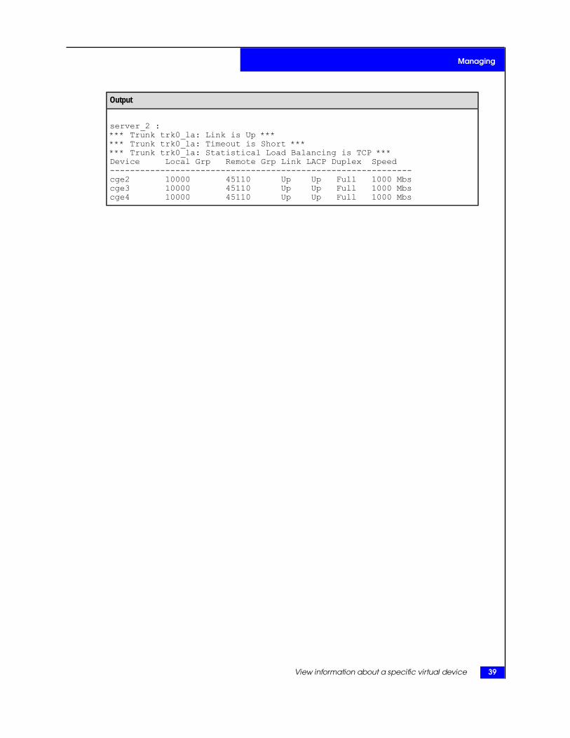
Output
server_2 :*** Trunk trk0_la: Link is Up ****** Trunk trk0_la: Timeout is Short ****** Trunk trk0_la: Statistical Load Balancing is TCP ***Device Local Grp Remote Grp Link LACP Duplex Speed------------------------------------------------------------cge2 10000 45110 Up Up Full 1000 Mbscge3 10000 45110 Up Up Full 1000 Mbscge4 10000 45110 Up Up Full 1000 Mbs
View information about a specific virtual device 39
Managing
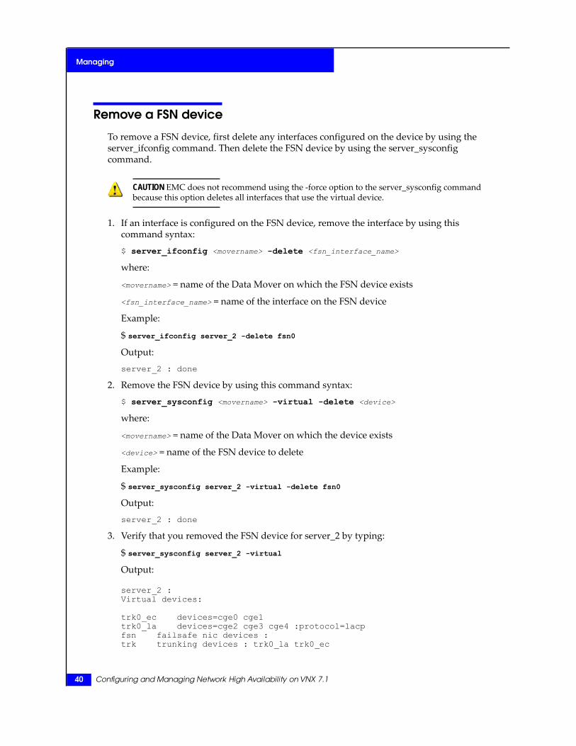
Remove a FSN device
To remove a FSN device, first delete any interfaces configured on the device by using theserver_ifconfig command. Then delete the FSN device by using the server_sysconfigcommand.
CAUTION EMC does not recommend using the -force option to the server_sysconfig commandbecause this option deletes all interfaces that use the virtual device.
1. If an interface is configured on the FSN device, remove the interface by using thiscommand syntax:
$ server_ifconfig <movername> -delete <fsn_interface_name>
where:
<movername> = name of the Data Mover on which the FSN device exists
<fsn_interface_name> = name of the interface on the FSN device
Example:
$ server_ifconfig server_2 -delete fsn0
Output:
server_2 : done
2. Remove the FSN device by using this command syntax:
$ server_sysconfig <movername> -virtual -delete <device>
where:
<movername> = name of the Data Mover on which the device exists
<device> = name of the FSN device to delete
Example:
$ server_sysconfig server_2 -virtual -delete fsn0
Output:
server_2 : done
3. Verify that you removed the FSN device for server_2 by typing:
$ server_sysconfig server_2 -virtual
Output:
server_2 :Virtual devices:
trk0_ec devices=cge0 cge1trk0_la devices=cge2 cge3 cge4 :protocol=lacpfsn failsafe nic devices :trk trunking devices : trk0_la trk0_ec
40 Configuring and Managing Network High Availability on VNX 7.1
Managing
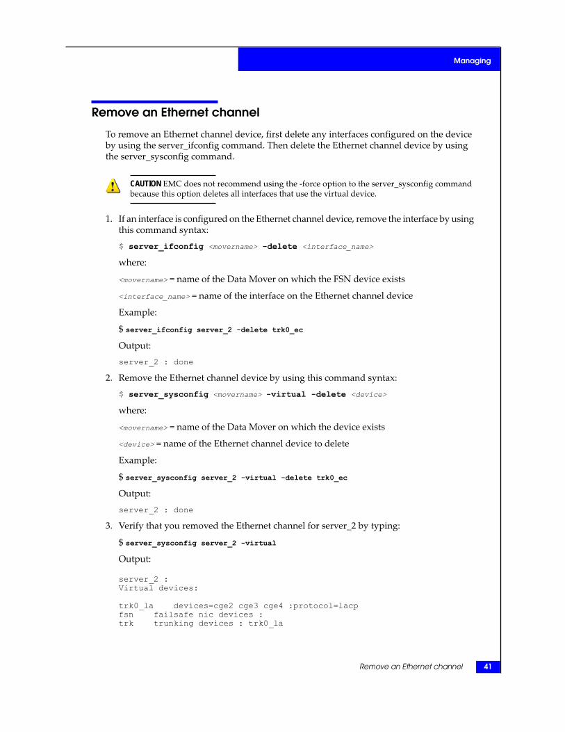
Remove an Ethernet channel
To remove an Ethernet channel device, first delete any interfaces configured on the deviceby using the server_ifconfig command. Then delete the Ethernet channel device by usingthe server_sysconfig command.
CAUTION EMC does not recommend using the -force option to the server_sysconfig commandbecause this option deletes all interfaces that use the virtual device.
1. If an interface is configured on the Ethernet channel device, remove the interface by usingthis command syntax:
$ server_ifconfig <movername> -delete <interface_name>
where:
<movername> = name of the Data Mover on which the FSN device exists
<interface_name> = name of the interface on the Ethernet channel device
Example:
$ server_ifconfig server_2 -delete trk0_ec
Output:
server_2 : done
2. Remove the Ethernet channel device by using this command syntax:
$ server_sysconfig <movername> -virtual -delete <device>
where:
<movername> = name of the Data Mover on which the device exists
<device> = name of the Ethernet channel device to delete
Example:
$ server_sysconfig server_2 -virtual -delete trk0_ec
Output:
server_2 : done
3. Verify that you removed the Ethernet channel for server_2 by typing:
$ server_sysconfig server_2 -virtual
Output:
server_2 :Virtual devices:
trk0_la devices=cge2 cge3 cge4 :protocol=lacpfsn failsafe nic devices :trk trunking devices : trk0_la
Remove an Ethernet channel 41
Managing

Remove a link aggregation
To remove a link aggregation device, first delete any interfaces configured on the device byusing the server_ifconfig command. Then delete the link aggregation device by using theserver_sysconfig command.
CAUTION EMC does not recommend using the -force option to the server_sysconfig commandbecause this option deletes all interfaces that use the virtual device.
1. If an interface is configured on the link aggregation, remove the interface by using thiscommand syntax:
$ server_ifconfig <movername> -delete <interface_name>
where:
<movername> = name of the Data Mover on which the FSN device exists
<interface_name> = name of the interface on the link aggregation
Example:
$ server_ifconfig server_2 -delete trk0_la
Output:
server_2 : done
2. Remove the link aggregation device by using this command syntax:
$ server_sysconfig <movername> -virtual -delete <device>
where:
<movername> = name of the Data Mover on which the device exists
<device> = name of the link aggregation device to delete
Example:
$ server_sysconfig server_2 -virtual -delete trk0_la
Output:
server_2 : done
3. Verify that you removed the link aggregation for server_2 by typing:
$ server_sysconfig server_2 -virtual
Output:
server_2 :Virtual devices:
fsn failsafe nic devices :trk trunking devices :
42 Configuring and Managing Network High Availability on VNX 7.1
Managing

Configure statistical load balancing on a Data Mover
To configure all Ethernet channels or link aggregations on a Data Mover to use the samemethod of statistical load balancing, use the trunk LoadBalance parameter.
You can configure statistical load balancing by IP addresses, TCP ports and IP addresses,or MAC addresses. The default method is by IP addresses.
If you use the server_sysconfig command to specify a load balancing value for a specificEthernet channel or link aggregation differing from the per-Data Mover setting, that valueoverrides the one set with the LoadBalance parameter. Configure an Ethernet channel onpage 22 and Configure link aggregation on page 27 provide information about using theload balancing with the server_sysconfig command.
Note: Restart the Data Mover to have these settings take effect.
Action
To enable statistical load balancing based on TCP ports and IP addressing, use this command syntax:
$ server_param <movername> -facility <facility_name> -modify <param_name>
-value <new_value>
where:
<movername> = name of the specified Data Mover
<facility_name> = name of the facility to which the parameter belongs; facility names are case-sensitive
<param_name> = name of the parameter; parameter names are case-sensitive
<new_value> = value to set for the specified parameter (ip (default), tcp, or mac)
Example:
To set the LoadBalance parameter to tcp, type:
$ server_param server_2 -facility trunk -modify LoadBalance -value tcp
Output
server_2 : done
Configure statistical load balancing on a Data Mover 43
Managing

44 Configuring and Managing Network High Availability on VNX 7.1
Managing

5
Troubleshooting
As part of an effort to continuously improve and enhance the performanceand capabilities of its product lines, EMC periodically releases new versionsof its hardware and software. Therefore, some functions described in thisdocument may not be supported by all versions of the software orhardware currently in use. For the most up-to-date information on productfeatures, refer to your product release notes.
If a product does not function properly or does not function as describedin this document, contact your EMC Customer Support Representative.
ProblemResolution Roadmap for VNX contains additional information aboutusing the EMC Online Support website and resolving problems.
Topics included are:◆ EMC E-Lab Interoperability Navigator on page 46◆ Tips for Ethernet channels and link aggregations on page 46◆ Tips for FSNs on page 47◆ Error messages on page 47◆ EMC Training and Professional Services on page 48
Configuring and Managing Network High Availability on VNX 7.1 45

EMC E-Lab Interoperability Navigator
The EMC E-Lab™ Interoperability Navigator is a searchable, web-based application thatprovides access to EMC interoperability support matrices. It is available on the EMC OnlineSupport website at http://Support.EMC.com. After logging in, locate the applicable Supportby Product page, find Tools, and click E-Lab Interoperability Navigator.
Tips for Ethernet channels and link aggregations
When diagnosing problems with Ethernet channels and link aggregations, remember trafficmight not travel over the same link in both directions. Traffic might come in over one linkand leave over another. However, if a Data Mover uses a TOE network interface card,inbound and outbound traffic travels through the same port. Using the same port is criticalbecause TOE devices store part of the TCP state. For every inbound connection to a TOEdevice, the system transfers the outbound connection to the port used by the switch for theinbound connection.
You can determine if the system is using a TOE device by using the server_sysconfig -pcicommand. If a TOE device is present, the output is: Alacritech Gigabit TOE.
To change the traffic flow for a TOE device, change the port that your switch uses. The DataMover accommodates that change. The documentation for your switch provides informationabout changing the port your switch uses.
One of the best tools for diagnosing problems with virtual devices is the server_sysconfig-virtual -info command.
If communication with some network nodes seems to function properly while communicationwith other nodes functions poorly or not at all, there is a probability that one or more of theswitch ports to which the physical ports of the virtual device are connected is not configuredconsistently with the other ports. To diagnose this problem:
1. Disconnect the network cables attached to ports that are part of the virtual device inquestion, one by one at the Data Mover.
2. Each time you disconnect a cable, use the switch commands to verify that one of thevirtual device’s physical links becomes disabled due to the loss of the link:
• For any cable disconnection that does not cause the physical link to become disabled,that port on the Data Mover is not connected to a physical port of the switch, whichis part of the same virtual device.
• This indicates a misconfiguration of the switch or cabling not matching the switchconfiguration.
To verify that the Data Mover and switch configurations match:
1. In turn, physically connect each port of the virtual device, as defined on the switch, asthe only connected port of the virtual device.
46 Configuring and Managing Network High Availability on VNX 7.1
Troubleshooting
2. While that port is the only connected port, generate traffic from the Data Mover (forinstance, by using the server_ping command) and ensure:
• The Data Mover is communicating successfully through that port of the virtual device.If communication fails, the virtual device configuration on the Data Mover does notmatch that of the switch for this port.
• The MAC address reported in every case is the same address that the switch learnedon the logical port of the virtual device.
3. Generate traffic on any other ports configured on the Data Mover that is not a part of thevirtual device in question:
• The switch should learn the same MAC address on the switch port of the virtualdevice.
• If more than one MAC address is reported on the switch port of the virtual device, aport on the Data Mover that is not part of the virtual device is connected to a switchport that is part of the virtual device.
Tips for FSNs
If the devices of a FSN are connected to different switches, it is critical that all switch portsof the FSN be configured to immediately switch from blocking mode to forwarding modeand not pass through spanning tree states of listening and learning when an interface comesup. On Cisco switches, this means the portfast capability must be enabled for each of theports connected between the switch and the constituent devices of the FSN.
This is necessary to guarantee that the switch forwards the Ethernet frame that the DataMover generates when a physical link is enabled. This is done on a port-to-port basis. Theportfast variable, when enabled, causes the port to immediately switch from blocking toforwarding mode. Do not use portfast on switch-to-switch connections.
If you notice a FSN device toggling between components, it might be because a primarydevice is configured and the primary device is having intermittent failures.
Error messages
All event, alert, and status messages provide detailed information and recommended actionsto help you troubleshoot the situation.
To view message details, use any of these methods:
◆ Unisphere software:
• Right-click an event, alert, or status message and select to view Event Details, AlertDetails, or Status Details.
Tips for FSNs 47
Troubleshooting
◆ CLI:
• Type nas_message -info <MessageID>, where <MessageID> is the messageidentification number.
◆ Celerra Error Messages Guide:
• Use this guide to locate information about messages that are in the earlier-releasemessage format.
◆ EMC Online Support website:
• Use the text from the error message's brief description or the message's ID to searchthe Knowledgebase on the EMC Online Support website. After logging in to EMCOnline Support, locate the applicable Support by Product page, and search for theerror message.
EMC Training and Professional Services
EMC Customer Education courses help you learn how EMC storage products work togetherwithin your environment to maximize your entire infrastructure investment. EMC CustomerEducation features online and hands-on training in state-of-the-art labs conveniently locatedthroughout the world. EMC customer training courses are developed and delivered by EMCexperts. Go to the EMC Online Support website at http://Support.EMC.com for course andregistration information.
EMC Professional Services can help you implement your system efficiently. Consultantsevaluate your business, IT processes, and technology, and recommend ways that you canleverage your information for the most benefit. From business plan to implementation, youget the experience and expertise that you need without straining your IT staff or hiring andtraining new personnel. Contact your EMC Customer Support Representative for moreinformation.
48 Configuring and Managing Network High Availability on VNX 7.1
Troubleshooting
Glossary
D
deviceTwo types of devices are physical (port) and virtual.
See also virtual device.
E
Ethernet channelHigh-availability feature that enables multiple active Ethernet connections to the same switchto appear as a single link with a single MAC address and potentially multiple IP addresses.
F
Fail-Safe Network (FSN)High-availability feature that extends link failover out into the network by providing switch-levelredundancy. A FSN appears as a single link with a single MAC address and potentially multipleIP addresses.
failoverProcess of immediately routing data to an alternate data path or device to avoid interruptingservices in the event of a failure. The impact to service is dependent on the application’s abilityto handle the change gracefully.
Fast EthernetAny Ethernet specification with a speed of 100 Mb/s. Based on the IEEE 802.3u specification.
G
Gigabit EthernetAny Ethernet specification with a speed of 1000 Mb/s. IEEE 802.3z defines Gigabit Ethernetover fiber and cable, which has a physical media standard of 1000Base-X (1000Base-SX shortwave, 1000Base-LX long wave) and 1000Base-CX shielded copper cable. IEEE 802.3ab definesGigabit Ethernet over an unshielded twisted pair (1000Base-T).
Configuring and Managing Network High Availability on VNX 7.1 49
I
Internet Protocol (IP)Network layer protocol that is part of the Open Systems Interconnection (OSI) reference model.IP provides logical addressing and service for end-to-end delivery.
IP interfaceNamed logical entity representing a physical device (a port) or a virtual device (a combinationof physical devices) and used to assign an IP address to the device. There may be multiple IPinterfaces associated with a single device.
L
linkWorking data connection between systems on a network. Also, a connection between two ormore ports.
link aggregationHigh-availability feature based on the IEEE 802.3ad Link Aggregation Control Protocol (LACP)standard which allows Ethernet ports with characteristics similar to the same switch to combineinto a single virtual device, or link with a single MAC address and potentially multiple IPaddresses.
M
media access control (MAC) addressData link hardware address every physical device (port) or virtual device needs to connect toa network segment. These addresses are used by network devices to locate the logical devices.
P
portPhysical connection point to a network or a number used at the transport layer to trackhost-to-host virtual circuits.
S
standby deviceDevice held in reserve against a failure of its active partner. When the active device fails, thestandby device takes over.
T
TCP Offload Engine (TOE)TOE network interface card offloads TCP protocol stack processing from the host and helpsimprove network performance and reduce CPU utilization.
Transmission Control Protocol (TCP)Connection-oriented transport protocol that provides reliable data delivery.
50 Configuring and Managing Network High Availability on VNX 7.1
Glossary
trunkSet of physical network devices bundled together for high availability. Ethernet channels andlink aggregations are trunks.
V
virtual deviceCombination of multiple physical devices defined by a single MAC address.
Configuring and Managing Network High Availability on VNX 7.1 51
Glossary

52 Configuring and Managing Network High Availability on VNX 7.1
Glossary
Index
Aand link aggregation
number of links 17
Ddevice
virtual 14duplex
and Ethernet channels 17and link aggregation 17
EEMC E-Lab Navigator 46error messages 47Ethernet channel 14, 16, 17, 18, 22, 24, 41, 46
and Port Aggregation Protocol 16automatic recovery 14bandwidth 14comparison to link aggregation 16configuring 22configuring IP interfaces 24duplex 17EtherChannel 16in a Fail-Safe Network 18, 22link speed 14, 17load balancing 17MAC address 16number of links 17overview 14problem diagnosis 46removing 41removing IP interfaces 41supported features 14switch characteristics 16switch configuration 16, 22
Ethernet channel (continued)switch mode 17
FFail-Safe Network
See FSN 17FSN
and Ethernet channels 18, 22, 31and link aggregations 18, 27, 31characteristics 19configuring 31examples 31, 33IP interfaces for 32maximum number of devices allowed 19overview 17primary device 18, 19problem diagnosis 47removing 40removing IP interfaces 40toggling 19, 47with multiple switches 47
IIEEE802.3ad
See link aggregation 15IP interface
configuring for Ethernet channels 24configuring for FSN 32configuring for link aggregations 29removing from Ethernet channels 41removing from FSN 40
Configuring and Managing Network High Availability on VNX 7.1 53
IP interface (continued)removing from link aggregations 42
LLACP
See link aggregation 15link aggregation
bandwidth 15characteristics 15comparison to Ethernet channel 16configuring IP interfaces 29duplex 17IEEE802.3ad 15in a Fail-Safe Network 18, 27LACP 15link speed 17link speed and duplex 15load balancing 17overview 15port configuration 15problem diagnosis 46removing 42removing IP interfaces 42switch characteristics 16switch configuration 27switch mode 17
link aggregationsconfiguring 27
link speedand Ethernet channels 14, 17and link aggregation 15, 17
load balancing 16, 17and Ethernet channels 17and link aggregation 17
LoadBalance parameter 43
MMAC address 16, 17, 19
and Ethernet channels 16and Fail-Safe Network devices 17
messages, error 47
Nnetwork
Ethernet channel 14Fail-Safe Network (FSN) 17
network (continued)link aggregation 15
PPAgP
See Ethernet channel 16Port Aggregation Protocol
See Ethernet channel 16primary device 18
Rremoving IP interfaces
from Ethernet channels 41
Sserver_ifconfig
configuring IP interfaces for Ethernet channels24configuring IP interfaces for FSNs 35configuring IP interfaces for link aggregations29removing IP interfaces from Ethernet channels41removing IP interfaces from FSNs 40removing IP interfaces from link aggregations42
server_sysconfigconfiguring Ethernet channels 33configuring FSNs 31, 34configuring link aggregations 28removing Ethernet channels 41removing FSNs 40removing link aggregations 42viewing virtual devices 38
statistical load balancingLoadBalance parameter 43per Data Mover 43
switch characteristics 16switch mode
and Ethernet channels 17and link aggregation 17
Ttroubleshooting 45
Vvirtual device 14virtual devices
54 Configuring and Managing Network High Availability on VNX 7.1
Index

virtual devices (continued)detailed information 38overview 14
virtual devices (continued)troubleshooting 46viewing 38
Configuring and Managing Network High Availability on VNX 7.1 55
Index
56 Configuring and Managing Network High Availability on VNX 7.1
Index