emc models. 2 june 15 1. models, what for ? 2. emc of ic model 3. core model 4. package models 5....
Post on 18-Dec-2015
229 views
TRANSCRIPT

EMC Models

2 18 Apr 2023
1. Models, what for ?
2. EMC of IC Model
3. Core Model
4. Package models
5. Emission measurements/simulations
6. Immunity measurements/simulations
7. Chip-to-chip Coupling
8. Future of EMC models
9. Conclusion
Summary

3 18 Apr 2023
IC designers want to predict EMC before fabrication
Models – What for ?
Noise margin
Switching Noise on Vdd
• IC designers want to predict power integrity and EMI during design cycle
to avoid redesign • EMC models and prediction tools have to be integrated to their design
flows

4 18 Apr 2023
© Siemens Automotive Toulouse
• Most of the time, EMC measurements are performed once the equipment is built.
• No improvements can be done at conception phase.• Predict EMC performances IC, board, equipment optimizations• However, need of non-confidential IC models (black box models)
Models – What for ?
Equipment designers want to predict EMC before fabrication

5 18 Apr 2023
Complexity
Level
Equipment
Board
Component
Physicalspice
V, Z
106 R,L,C,ILEECS
ICEM
Dipoles
102 R,L,C,I
101 R,L,C,I
101 dipoles
100 V(f), 100 Z(f)
x-highhighlow medium
Expo PowerSI
104 R,L,C,I
EMC Models depends on the targeted complexity, the level of confidentiality of information.
Confidentiality
EMC of IC models

6 18 Apr 2023
Model of the package using R,L,C
Core
Model of the die :• internal activity (core)• on-chip decoupling• supply network • I/O structure
Core
Package
IC
EMC of IC model
The model of an IC can be derived from its physical architecture.
It includes the core and package model.

7 18 Apr 2023
EMC of IC models
Core – I/O Model
Package ModelTest bench Model Test board Model
EMC Model for the circuit
Electrical Simulation
Simulated Emission spectrum
General flow to build an EMC model and predict EMC performances

8 18 Apr 2023
EMC of IC modelsEMC of IC models
How establishing an EMC of IC model ?
From layout From floorplan estimation
Without IC confidential information
Internal Activity
I(t) simulation Estimated current source model for each block
External i(t) measurement internal current extraction
On-chip decoupling
Layout extraction Estimated on-chip capacitance for each block
S parameter measurements
Supply Network
RC Layout extraction
RC Layout extraction S parameter measurements Power supply placement from
datasheet
I/O Full model of I/O I(V) characteristic from IBIS file
Package Measurement 3D EM simulation IBIS package data
Objectives Accurate prediction, check EMC performances
Feasibility study, 1st noise evaluation, optimization of on-chip and supply pairs placement
Provide model to predict EMC compliance of an entire system
blockinfo
9 18 Apr 2023
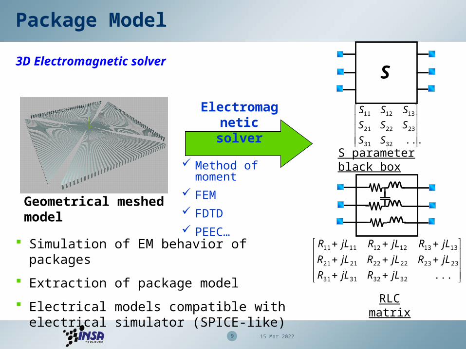
Package Model
3D Electromagnetic solver
Geometrical meshed model
...3231
232221
131211
SS
SSS
SSS
...32323131
232322222121
131312121111
jLRjLR
jLRjLRjLR
jLRjLRjLR
S
Electromagnetic solver
Method of moment FEM FDTD PEEC…
Simulation of EM behavior of packages
Extraction of package model
Electrical models compatible with electrical simulator (SPICE-like)
S parameter black box
RLC matrix

10 18 Apr 2023
Package Model
S parameters extraction
Vector Network Analyzer
Coplanar probe
Package
Extraction of package model from measurement
Calibration plane issues from hundreds of MHz
Require good knowledge in RF measurement

11 18 Apr 2023
Core model
Supply network model
Complex network of interconnections, vias and on-chip capacitances Coupling path for noise through the IC Require extraction of impedance between Vdd and Vss. Possible modeling by an equivalent passive model
Equivalent passive model
Substrate, interconnections metallization
Capacitive behavior

12 18 Apr 2023
100 mA
3 A
32 bit processor500 MHz
62.5 ns 2 ns
16 bit processor
16 MHz
I
time
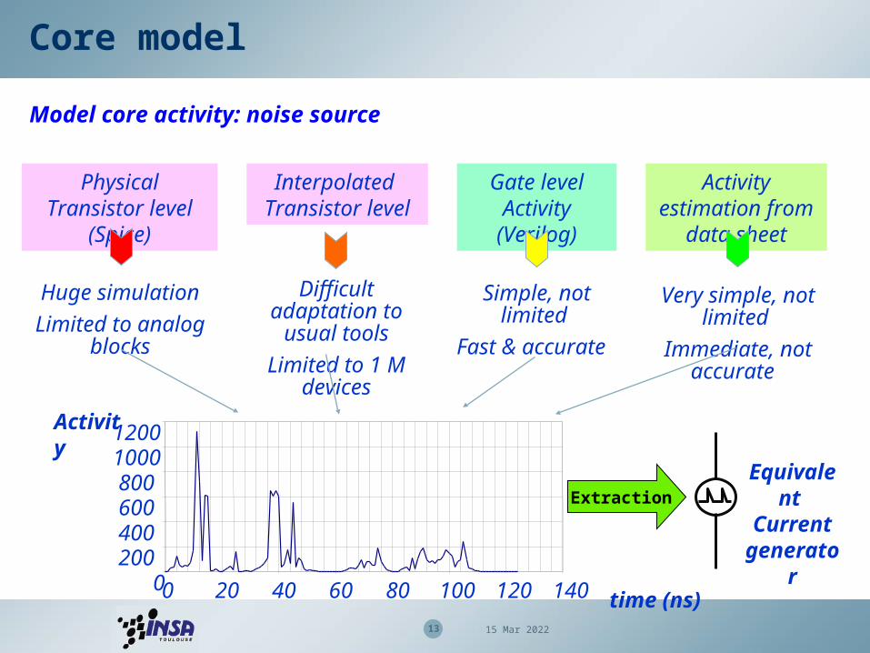
Core model
Model core activity : extract noise source
time
I
Extraction of internal current waveform
1st order assumption : model core activity by triangular waveform current source
13 18 Apr 2023
Physical Transistor level (Spice)
Huge simulation
Limited to analog blocks
Interpolated Transistor level
Difficult adaptation to usual tools
Limited to 1 M devices
Simple, not limited
Fast & accurate
Gate level Activity (Verilog)
time (ns)0
20040060080010001200
0 20 40 60 80 100 120 140
Activity
Activity estimation from data sheet
Very simple, not limited
Immediate, not accurate
Core model
Model core activity: noise source
Equivalent Current
generatorExtraction

14 18 Apr 2023
Core model
Model The IC using a complete power supply distribution network
Chip model
Package model Floorplanning, physical layout
Package modelChip model
Elementary cell
Vdd1
Vss1
Vdd2
Vss2
Full chip switching noise analysis, mapping of voltage drop, evaluation of power integrity, crosstalk, EMI, effect of on-chip decoupling.
Very accurate but large netlists.
Too much complex to add PCB model.
Adapted for IC designer issues.

15 18 Apr 2023
PowerSI - Real-time voltage noise simulation (right), including on-chip decoupling capacitors, shows a more stable on-chip power supply © Sigrity http://www.sigrity.com
Core model
Model core activity: Tool example
Layout Silicium voltage drop map

16 18 Apr 2023
Core model
Model The IC using double LC system
Emission Level (dBµV)
Frequency (MHz)
Example of measurement of IC conducted emission
Envelop of spectrum
1st resonance
2nd resonance

17 18 Apr 2023
Package model IC model
Core model
Model The IC using double LC system
Ib
Rvdd
Cd
Lvdd
Rvss Lvss
Cb
LPackVdd
LPackVss
External VDD
External VSS
ICEM model(IEC 62014-3)
Secondary resonance
Primary resonance
Frequency
Emission level
Low L,C values =>
High resonant frequency

18 18 Apr 2023
[Component] Fx45H725 [Manufacturer] Finex[Package]| variable typ min max|R_pkg 800m 500m 950m L_pkg 6nH 5.5nH 7.5nHC_pkg 8pF 4pF 10.5pF[Pin] signal model R_pin L_pin C_pin1 /1OE in1 921m 7.25nH 10.1pF2 1Y1 out 1 916m 7.17nH 9.94pF…
[Component] Fx45H725 [Manufacturer] Finex[Package]| variable typ min max|R_pkg 800m 500m 950m L_pkg 6nH 5.5nH 7.5nHC_pkg 8pF 4pF 10.5pF[Pin] signal model R_pin L_pin C_pin1 /1OE in1 921m 7.25nH 10.1pF2 1Y1 out 1 916m 7.17nH 9.94pF…
IO Model
IBIS: Input Buffer I/O specification
IBIS fileIBIS file
I/O switching noise prediction I/O immunity prediction
Very important for :
Input driver I(V) characteristics
Input driver I(V) characteristics
Output driver I(V) characteristics
Output driver I(V) characteristics

19 18 Apr 2023
Test bench model
DPI capacitance
C=1nF
L=0.5nH
R=15mΩ
Electrical model extracted by S parameter measurements and electromagnetic simulations
Test bench models should be generic
Limited frequency range due to influence of parasitic elements, apparition of high order propagation mode
Test bench model
TEM CellDPI injection
DUT
TEM
K=1%C=20fF
Near-field scanDUT
K=6%
L=4nHR=1Ω

20 18 Apr 2023
1 To receiver
DUT
Emission measurement/simulation
Conducted/Radiated emission prediction
Time Domain Simulation
FFT of Vanalyzer(t)
EMC model
Measurements
Core Model
Elec. package Model
BoardModel
IC Model
Spectrum analyzer
Compare spectrums
Simulations Measurements
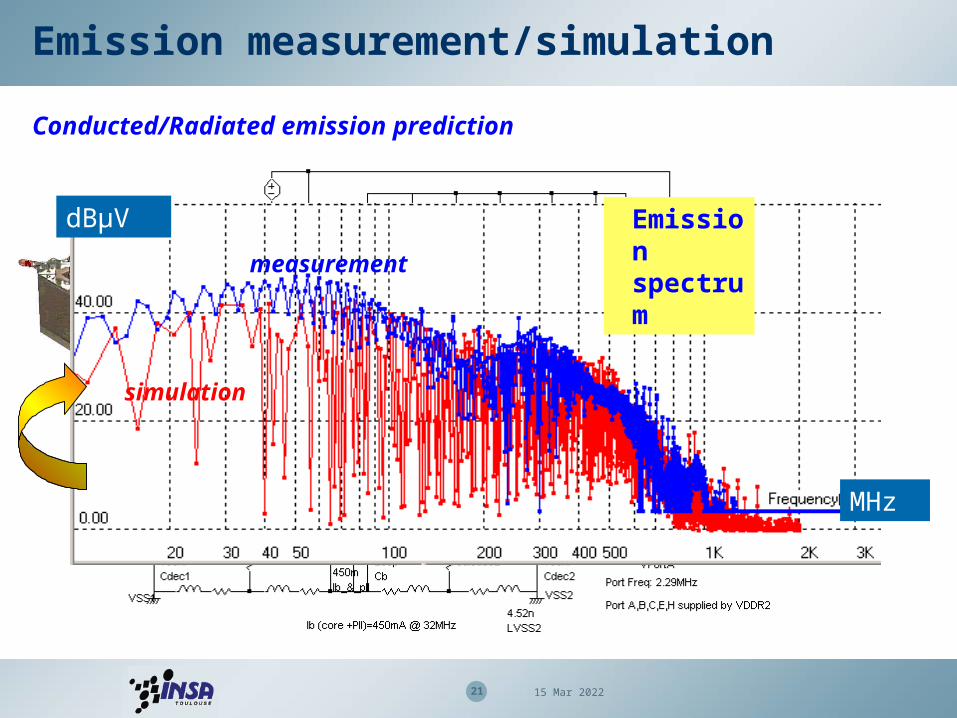
21 18 Apr 2023
ICEM model
dBµV
MHz
Emission spectrummeasurement
simulation
Conducted/Radiated emission prediction
Emission measurement/simulation

22 18 Apr 2023
Emission measurement/simulation
Near field method - theory
chip
Vdd
Vss
I(vdd)
I(vss)
P
H1
H2
i
iHPH
r P
H
IL
Package is the main contributor of the radiated emission of an IC
Magnetic field emission is generated by the flowing of parasitic current through package pins
Magnetic near field scan of a 16 bit microcontroller

23 18 Apr 2023
Scan Simulations
Core Model
Elec. package Model
Analog Time Domain Simulation
Fourier Transform of I(t)
Compare scans
Scan Measurements
Spectrum analyser
H[x,y] at given f, given z
Positionning [x,y]
Emission measurement/simulation
Near field method – prediction principle
Geometrical package model
VssX1 VssA
VssX2VssR2
Vss2
Vdd2
Vss1
Vdd1
VssR1 VddR1
H[x,y,z] of I(f)

24 18 Apr 2023
Emission measurement/simulation
Near-field scan: S12X case study (144 pins, 0.25µm)
Simulation of H field at
32 MHz
Measurement of H field
at 32 MHz
Scan area
Package model with 13 leads

25 18 Apr 2023
Susceptibility measurement/simulation
Susceptibility prediction model
Functional model
outputinput
clock
Vdd
Vss
Resonance
I/O
Supply network Z(f)
Time
Amplitude
Disturbance model
IC model
ICEMIBISCoupling
path model
ICIM draft standard (Integrated Circuit immunity Model)
Reuse of standard non-confidential models (ICEM, IBIS)
Susceptibility peaks linked with supply network anti-resonances

26 18 Apr 2023
Susceptibility measurement/simulation
Susceptibility simulation flow
Aggressed IC Model (ICEM)
Package and IO model (IBIS)
RFI and coupling path model (Z(f))
Set RFI frequencyIC-EMC
Increase V aggressor
Time domain simulation
WinSPICE
Criterion analysis
Extract forward power
IC-EMC
Increase RFI frequency
Susceptibility threshold simulation

27 18 Apr 2023
Susceptibility measurement/simulation
16 bit micro-controller I/O susceptibility prediction
• 16 bit micro-controller• Direct power injection• Input buffer aggression• Sinusoidal mode• Simulation criterion:
Logical change of input buffer
From A. Boyer’s PhD, INSA, 2007

28 18 Apr 2023
• EMC models can help earn/save money
• Macro-models of ICs include core, I/O and package modeling
• The core model is based on current evaluation and on-chip
capacitance
• The package model is based on RLC
• Good prediction of emission and susceptibility up to 2 GHz
• Soon, requirements up to 3-10 GHz
Conclusion