emc compliance report in accordance with: en 61000-6-2: … · en 61000-6-2: 2005 seeley...
TRANSCRIPT
EMC Bayswater Pty Ltd
EMC ENGINEERS & LABORATORIES
18/88 Merrindale Drive Croydon South, Victoria, 3136, Australia Telephone: +61 3 9761 5888 Facsimile: +61 3 8761 6547 Email: [email protected] ABN: 49 112 221 333
EMC COMPLIANCE REPORT In accordance with: EN 61000-6-2: 2005
Seeley International Pty Ltd
ENV
Fixed Evaporative Air Cooler
REPORT: E1402-0421-2 DATE: February, 2014
Accreditation Number: 18553 Accredited for compliance with ISO/IEC 17025
The results of the tests, calibrations and/or measurements included in this document are traceable to Australian/national standards.
EMC Bayswater Test Report E1402-0421-2
Page 2 of 32
Prepared by:
Approved by:
20 February 2014 10:12
Neville Liyanapatabendige (EMC Test Engineer)
Fabio D’Amico (EMC Test Officer)
Andrew Whiteford (General Manager)
Date
Accreditation number: 18553. The results of the tests, calibrations and/or measurements included in this document are traceable to Australian/national standards. This document may not be reproduced except in full, without approval from EMC Bayswater.
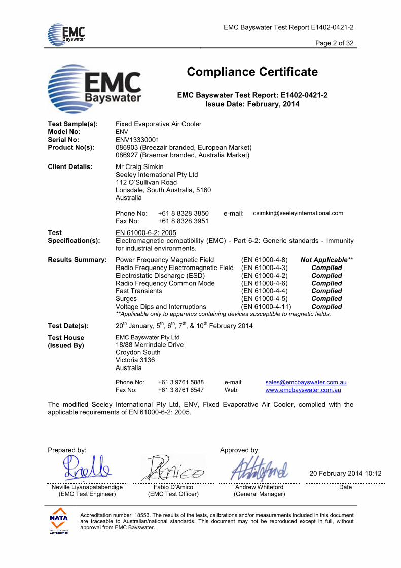
Compliance Certificate
EMC Bayswater Test Report: E1402-0421-2 Issue Date: February, 2014
Test Sample(s): Fixed Evaporative Air Cooler Model No: ENV Serial No: ENV13330001 Product No(s): 086903 (Breezair branded, European Market) 086927 (Braemar branded, Australia Market)
Mr Craig Simkin Seeley International Pty Ltd 112 O’Sullivan Road Lonsdale, South Australia, 5160 Australia Phone No: +61 8 8328 3850 e-mail: [email protected]
Client Details:
Fax No: +61 8 8328 3951
Test Specification(s):
EN 61000-6-2: 2005 Electromagnetic compatibility (EMC) - Part 6-2: Generic standards - Immunity for industrial environments.
Power Frequency Magnetic Field (EN 61000-4-8) Not Applicable**
Radio Frequency Electromagnetic Field (EN 61000-4-3) Complied
Electrostatic Discharge (ESD) (EN 61000-4-2) Complied
Radio Frequency Common Mode (EN 61000-4-6) Complied Fast Transients (EN 61000-4-4) Complied
Results Summary:
Surges (EN 61000-4-5) Complied Voltage Dips and Interruptions (EN 61000-4-11) Complied **Applicable only to apparatus containing devices susceptible to magnetic fields.
Test Date(s): 20th January, 5
th, 6
th, 7
th, & 10
th February 2014
Test House (Issued By)
EMC Bayswater Pty Ltd
18/88 Merrindale Drive Croydon South Victoria 3136 Australia
Phone No: +61 3 9761 5888 e-mail: [email protected]
Fax No: +61 3 8761 6547 Web: www.emcbayswater.com.au
The modified Seeley International Pty Ltd, ENV, Fixed Evaporative Air Cooler, complied with the applicable requirements of EN 61000-6-2: 2005.

EMC Bayswater Test Report E1402-0421-2
Page 3 of 32
Accreditation number: 18553. The results of the tests, calibrations and/or measurements included in this document are traceable to Australian/national standards. This document may not be reproduced except in full, without approval from EMC Bayswater.
EMC Compliance Report for
Seeley International Pty Ltd
Contents
1. Introduction...................................................................................................................................... 4
2. Summary of Results........................................................................................................................ 4
3. Product Sample, Configuration & Modifications ......................................................................... 4 3.1. Product Sample Details ............................................................................................................ 4 3.2. EUT Configuration .................................................................................................................... 5 3.3. Modifications............................................................................................................................. 5 3.4. Monitoring................................................................................................................................. 5
4. Test Facility & Equipment .............................................................................................................. 5 4.1. Test Facility .............................................................................................................................. 5 4.2. Test Equipment ........................................................................................................................ 5
5. Referenced Standards .................................................................................................................... 6
6. Performance (Pass/Fail) Criteria.................................................................................................... 7
7. Radio-Frequency Electromagnetic Field (EN 61000-4-3) ............................................................ 8 7.1. Requirements ........................................................................................................................... 8 7.2. Test Procedure ......................................................................................................................... 8 7.3. Test Results.............................................................................................................................. 8
8. Electrostatic Discharge (EN 61000-4-2) ...................................................................................... 10 8.1. Requirements ......................................................................................................................... 10 8.2. Test Procedure ....................................................................................................................... 10 8.3. Discharge Points .................................................................................................................... 10 8.4. Test Results............................................................................................................................ 11
9. Radio-Frequency Common Mode (EN 61000-4-6) ...................................................................... 12 9.1. Requirements ......................................................................................................................... 12 9.2. Test Procedure ....................................................................................................................... 12 9.3. Test Results............................................................................................................................ 12
10. Fast Transients (EN 61000-4-4) .................................................................................................... 14 10.1. Requirements ......................................................................................................................... 14 10.2. Test Procedure ....................................................................................................................... 14 10.3. Test Results............................................................................................................................ 14
11. Surges (EN 61000-4-5) .................................................................................................................. 16 11.1. Requirements ......................................................................................................................... 16 11.2. Test Procedure ....................................................................................................................... 16 11.3. Test Results............................................................................................................................ 17
12. Voltage Dips and Interruptions (EN 61000-4-11) ........................................................................ 19 12.1. Requirements ......................................................................................................................... 19 12.2. Test Procedure ....................................................................................................................... 19 12.3. Test Results............................................................................................................................ 19
13. Conclusion ..................................................................................................................................... 20
Appendix A – Test Equipment............................................................................................................ 21
Appendix B – Photographs................................................................................................................. 23

EMC Bayswater Test Report E1402-0421-2
Page 4 of 32
Accreditation number: 18553. The results of the tests, calibrations and/or measurements included in this document are traceable to Australian/national standards. This document may not be reproduced except in full, without approval from EMC Bayswater.
1. Introduction
Electromagnetic Compatibility (EMC) tests were performed on a Seeley International Pty Ltd, ENV, Fixed Evaporative Air Cooler, in accordance with the applicable requirements of EN 61000-6-2: 2005.
2. Summary of Results
Test Result
Radio Frequency Electromagnetic Field Complied, Criterion A
Electrostatic Discharge (ESD) Complied, Criterion A
Radio Frequency Common Mode – Signal Ports Complied, Criterion A
Radio Frequency Common Mode – Input AC Power Ports Complied, Criterion A
Fast Transients – Signal Ports Complied, Criterion B
Fast Transients – Input AC Power Ports Complied, Criterion A
Surges – Signal Ports Complied, Criterion A
Surges – Input AC Power Ports Complied, Criterion A
Voltage Dips Complied, Criterion A
Voltage Interruptions Complied, Criterion C
Table 1: Summary of test results
3. Product Sample, Configuration & Modifications
3.1. Product Sample Details
The EUT (Equipment Under Test), as supplied by the client, is described as follows: Product: Fixed Evaporative Air Cooler Model No: ENV Serial No: ENV13330001 Product No: 086903 Specifications: 380-415VAC, 50Hz (3 phase with neutral), 6.5A per phase
The EUT is a large commercial/industrial evaporative cooler, used to provide ventilation and cooling to offices, workshops and warehouses. The highest internal frequency of the device is 8MHz. (Refer to Photographs in Appendix B for views of the EUT)
EMC Bayswater Test Report E1402-0421-2
Page 5 of 32
Accreditation number: 18553. The results of the tests, calibrations and/or measurements included in this document are traceable to Australian/national standards. This document may not be reproduced except in full, without approval from EMC Bayswater.
3.2. EUT Configuration
The EUT was supplied with 415VAC, 50Hz (3 phase with neutral). A wall controller and a BMS controller were connected to the EUT. The Customer supplied and configured the EUT to operate in ventilation mode (fan only operation, operation of water circulation and drain pumps did not occur) and fan speed was set to mid level. The EUT was placed on a 105cm height metallic support with 100mm radius rubber wheels (customer supplied the EUT with metallic frame support).
3.3. Modifications
Modifications were made by the customer to the EUT to comply with Radiated Disturbance and Mains Terminal disturbance testing (refer to E1401-0421-1 emission test report for detailed information).
3.4. Monitoring
Wall controller display was monitored visually in person or via a CCTV camera system and by listening to the operation of fan motors (operating noise) during testing. Correct EUT functionality was verified after each test.
4. Test Facility & Equipment
4.1. Test Facility
Tests were performed inside an anechoic chamber or a standard shielded enclosure, where applicable, at EMC Bayswater Pty Ltd, located at 18/88 Merrindale Drive, Croydon South, Victoria, 3136, Australia. Fast transients, Surges, Voltage dips and interruptions were performed inside the indoor Open Area Test Site (iOATS) facility at EMC Technologies Pty Ltd, located at 176 Harrick Road, Keilor Park, Victoria, 3042, Australia.
4.2. Test Equipment
Refer to Appendix A for the measurement instrument list.
EMC Bayswater Test Report E1402-0421-2
Page 6 of 32
Accreditation number: 18553. The results of the tests, calibrations and/or measurements included in this document are traceable to Australian/national standards. This document may not be reproduced except in full, without approval from EMC Bayswater.
5. Referenced Standards
EN 61000-6-2: 2005 Electromagnetic compatibility (EMC) - Part 6-2: Generic standards - Immunity for industrial environments.
EN 61000-4-2: 1996 Electromagnetic Compatibility – Part 4. Testing and measurement techniques. Section 2. Electrostatic discharge immunity test.
EN 61000-4-3: 2006 Electromagnetic Compatibility – Part 4. Testing and measurement techniques. Section 3. Radiated, radio frequency, electromagnetic field immunity test. EN 61000-4-4: 2004 Electromagnetic Compatibility – Part 4. Testing and measurement techniques. Section 4. Electrical Fast Transient/burst immunity test. EN 61000-4-5: 2006 Electromagnetic Compatibility – Part 4. Testing and measurement techniques. Section 5. Surge Immunity test. EN 61000-4-6: 2007 Electromagnetic Compatibility – Part 4. Testing and measurement techniques. Section 6. Immunity to conducted disturbances, induced by radio-frequency fields. EN 61000-4-8: 2001 Electromagnetic Compatibility – Part 4. Testing and measurement techniques. Section 8. Power frequency magnetic field immunity test. EN 61000-4-11: 2004 Electromagnetic compatibility (EMC) - Testing and measurement techniques – Part 4. Voltage dips, short interruptions and voltage variations immunity tests
EMC Bayswater Test Report E1402-0421-2
Page 7 of 32
Accreditation number: 18553. The results of the tests, calibrations and/or measurements included in this document are traceable to Australian/national standards. This document may not be reproduced except in full, without approval from EMC Bayswater.
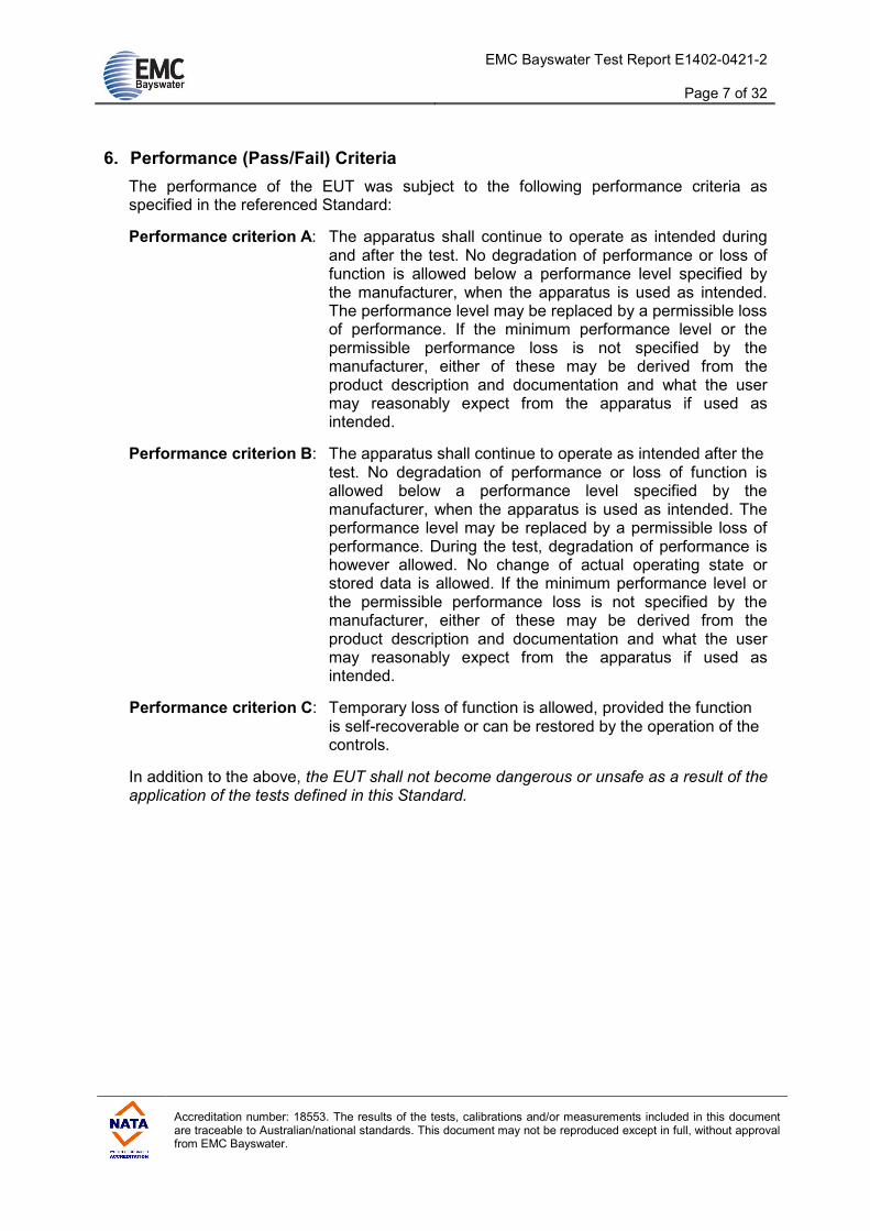
6. Performance (Pass/Fail) Criteria
The performance of the EUT was subject to the following performance criteria as specified in the referenced Standard:
Performance criterion A: The apparatus shall continue to operate as intended during and after the test. No degradation of performance or loss of function is allowed below a performance level specified by the manufacturer, when the apparatus is used as intended. The performance level may be replaced by a permissible loss of performance. If the minimum performance level or the permissible performance loss is not specified by the manufacturer, either of these may be derived from the product description and documentation and what the user may reasonably expect from the apparatus if used as intended.
Performance criterion B: The apparatus shall continue to operate as intended after the test. No degradation of performance or loss of function is allowed below a performance level specified by the manufacturer, when the apparatus is used as intended. The performance level may be replaced by a permissible loss of performance. During the test, degradation of performance is however allowed. No change of actual operating state or stored data is allowed. If the minimum performance level or the permissible performance loss is not specified by the manufacturer, either of these may be derived from the product description and documentation and what the user may reasonably expect from the apparatus if used as intended.
Performance criterion C: Temporary loss of function is allowed, provided the function is self-recoverable or can be restored by the operation of the controls.
In addition to the above, the EUT shall not become dangerous or unsafe as a result of the application of the tests defined in this Standard.
EMC Bayswater Test Report E1402-0421-2
Page 8 of 32
Accreditation number: 18553. The results of the tests, calibrations and/or measurements included in this document are traceable to Australian/national standards. This document may not be reproduced except in full, without approval from EMC Bayswater.
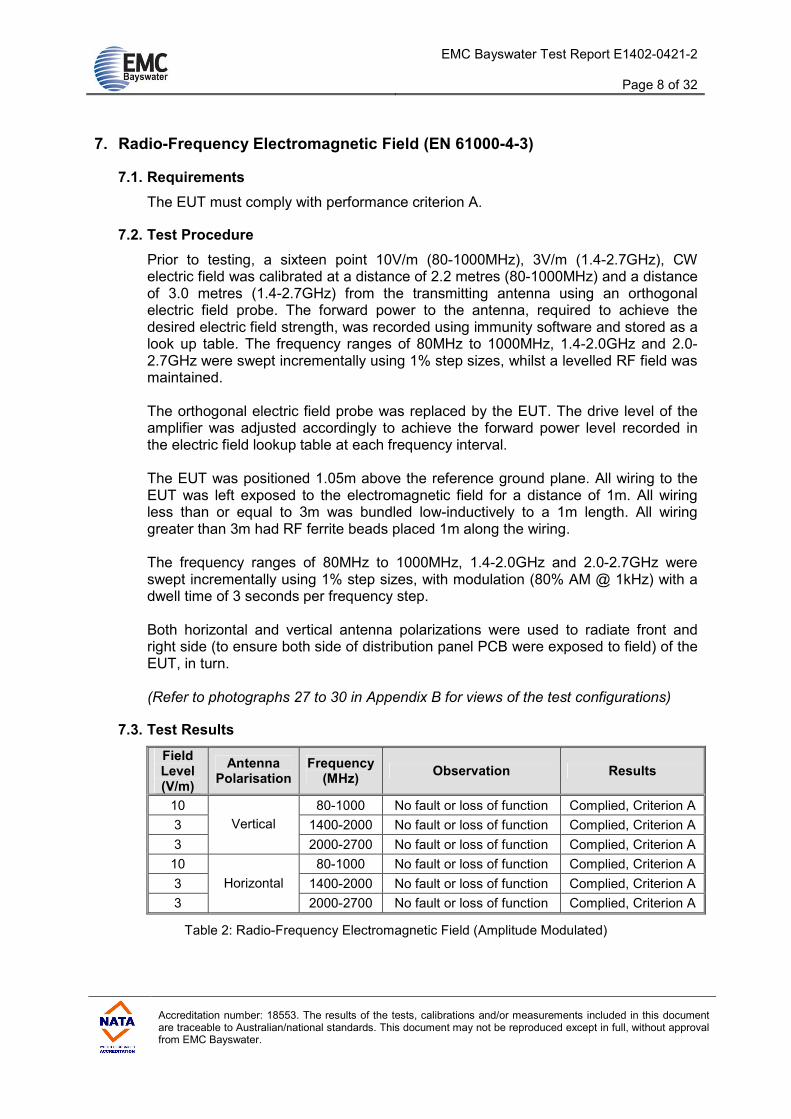
7. Radio-Frequency Electromagnetic Field (EN 61000-4-3)
7.1. Requirements
The EUT must comply with performance criterion A.
7.2. Test Procedure
Prior to testing, a sixteen point 10V/m (80-1000MHz), 3V/m (1.4-2.7GHz), CW electric field was calibrated at a distance of 2.2 metres (80-1000MHz) and a distance of 3.0 metres (1.4-2.7GHz) from the transmitting antenna using an orthogonal electric field probe. The forward power to the antenna, required to achieve the desired electric field strength, was recorded using immunity software and stored as a look up table. The frequency ranges of 80MHz to 1000MHz, 1.4-2.0GHz and 2.0-2.7GHz were swept incrementally using 1% step sizes, whilst a levelled RF field was maintained. The orthogonal electric field probe was replaced by the EUT. The drive level of the amplifier was adjusted accordingly to achieve the forward power level recorded in the electric field lookup table at each frequency interval. The EUT was positioned 1.05m above the reference ground plane. All wiring to the EUT was left exposed to the electromagnetic field for a distance of 1m. All wiring less than or equal to 3m was bundled low-inductively to a 1m length. All wiring greater than 3m had RF ferrite beads placed 1m along the wiring. The frequency ranges of 80MHz to 1000MHz, 1.4-2.0GHz and 2.0-2.7GHz were swept incrementally using 1% step sizes, with modulation (80% AM @ 1kHz) with a dwell time of 3 seconds per frequency step. Both horizontal and vertical antenna polarizations were used to radiate front and right side (to ensure both side of distribution panel PCB were exposed to field) of the EUT, in turn. (Refer to photographs 27 to 30 in Appendix B for views of the test configurations)
7.3. Test Results
Field Level (V/m)
Antenna Polarisation
Frequency (MHz)
Observation Results
10 80-1000 No fault or loss of function Complied, Criterion A
3 1400-2000 No fault or loss of function Complied, Criterion A
3
Vertical
2000-2700 No fault or loss of function Complied, Criterion A
10 80-1000 No fault or loss of function Complied, Criterion A
3 1400-2000 No fault or loss of function Complied, Criterion A
3
Horizontal
2000-2700 No fault or loss of function Complied, Criterion A
Table 2: Radio-Frequency Electromagnetic Field (Amplitude Modulated)

EMC Bayswater Test Report E1402-0421-2
Page 9 of 32
Accreditation number: 18553. The results of the tests, calibrations and/or measurements included in this document are traceable to Australian/national standards. This document may not be reproduced except in full, without approval from EMC Bayswater.
Climatic Conditions
Temperature: 26°C - 31°C
Humidity: 29% - 34%
Table 3: Climatic conditions
Comments: No fault or loss of function was observed.
In the frequency range of 2GHz to 2.7GHz an electric field of 3V/m CW was calibrated instead of 1V/m as required in the standard. This was done to ensure that 1V/m was achieved. The EUT was effectively over tested in this range.
Assessment: The EUT complied with the Radio-Frequency Electromagnetic Field immunity requirements of EN 61000-6-2: 2005, performance criterion A.

EMC Bayswater Test Report E1402-0421-2
Page 10 of 32
Accreditation number: 18553. The results of the tests, calibrations and/or measurements included in this document are traceable to Australian/national standards. This document may not be reproduced except in full, without approval from EMC Bayswater.
8. Electrostatic Discharge (EN 61000-4-2)
8.1. Requirements
The EUT must comply with performance criterion B.
8.2. Test Procedure
A Horizontal Coupling Plane (HCP), 1.6m x 0.8m was placed on top of a wooden table 0.8m high, standing on the ground reference plane. The EUT (Wall Controller) and cables were isolated from the coupling plane by an insulating film 0.5mm thick. The cooler was placed on a metallic support, 1.05m above the ground reference plane.
• Both contact and air discharge were applied (as applicable) to: - all faces and access points of the EUT - the Vertical Coupling Plane (VCP) - the Horizontal Coupling Plane (HCP)
• All coupling planes were connected to the ground reference plane via a
strap with a 470kΩ resistor located at each end.
• Contact discharges were applied to all conductive surfaces and to the coupling planes. Air discharges were applied only to the insulating surfaces.
• Discharges applied to the HCP and VCP were applied on each side of the EUT. Discharges made to the HCP were applied 0.1m from the EUT. Discharges made to the VCP were applied to the centre of one vertical edge of the coupling plane. The VCP (0.5m x 0.5m), was placed parallel to and positioned 0.1m from the EUT.
• The test voltage was increased from the minimum to the selected test level, in order to determine any threshold of failure.
• The test voltage was increased from the minimum (contact: ±2kV, air: ±2kV) to the selected test level (contact: ±4kV, air: ±8kV), in order to determine any threshold of failure.
• At least 10 single discharges were applied in both positive and negative
polarities at ±4.0kV for HCP, VCP and contact discharge and at ±8.0kV for air discharges.
(Refer to photographs 31 to 35 in Appendix B for views of the test configurations)
8.3. Discharge Points
Indirect contact discharges were applied to the Horizontal Coupling Plane (HCP) at the following positions:
• Front & Rear of EUT (Wall Controller only)
• Right and Left hand sides of EUT (Wall Controller only) Indirect contact discharges were applied to the Vertical Coupling Plane (VCP) with the EUT at the following positions:
• Front & Rear of EUT
• Right and left hand sides of EUT

EMC Bayswater Test Report E1402-0421-2
Page 11 of 32
Accreditation number: 18553. The results of the tests, calibrations and/or measurements included in this document are traceable to Australian/national standards. This document may not be reproduced except in full, without approval from EMC Bayswater.
Direct contact discharges were applied to the following points (Test points 1 to 15):
• All over the EUT (conductive surfaces, screws and connectors) Direct air discharges were applied to the following points (Test points A to D):
• Insulated surfaces, connectors and connector casings
• Insulated push buttons
• Insulated Display (Refer to photographs 36 to 39 in Appendix B for views of the test points)
8.4. Test Results
Indirect Application
Application ESD
Voltage Observation Results
±2.0 kV HCP
±4.0 kV No fault or loss of function detected Complied, Criterion A
±2.0 kV VCP
±4.0 kV No fault or loss of function detected Complied, Criterion A
Table 4: Electrostatic Discharges – Indirect Application
Direct Application – Contact Discharge
Application ESD
Voltage Observation Results
±2.0 kV 1 to 15
±4.0 kV No fault or loss of function detected Complied, Criterion A
Table 5: Electrostatic Discharges – Contact discharge
Direct Application – Air Discharge
Application ESD
Voltage Observation Results
±4.0 kV A to D
±8.0 kV No fault or loss of function detected Complied, Criterion A
Table 6: Electrostatic Discharges – Air discharge
Climatic Conditions
Temperature: 26-29°C
Humidity: 32-33%
Table 7: Climatic conditions
Comments: No fault or loss of function was observed.
Assessment: The EUT complied with the ESD requirements of EN 61000-6-2:
2005, performance criterion A.

EMC Bayswater Test Report E1402-0421-2
Page 12 of 32
Accreditation number: 18553. The results of the tests, calibrations and/or measurements included in this document are traceable to Australian/national standards. This document may not be reproduced except in full, without approval from EMC Bayswater.
9. Radio-Frequency Common Mode (EN 61000-4-6)
9.1. Requirements
The EUT must comply with performance criterion A.
9.2. Test Procedure
The EUT was placed on a metallic support, 1.05m above the ground reference plane. All coupling and decoupling devices were placed in direct contact with the elevated ground reference plane and at a distance of 0.3m away from the EUT. Cables running to the EUT were kept as short as possible and were not bundled or wrapped. The cables were kept between 30 mm to 50 mm above the ground reference plane. A signal generator was used to provide a drive signal to an RF power amplifier, which in turn provided the drive level to the coupling device. A Bulk Current Injection (BCI) probe was used to apply the RF signal to AC mains and signal/control cables, in turn.
A 10Vrms pre-calibrated (CW calibration using a 50Ω system) RF signal was applied to the coupling device with modulation (AM, 80%, 1kHz) over the frequency range of 0.150 MHz to 80 MHz. The frequency was incremented using 1% step sizes with a dwell time of 3 seconds. (Refer to photographs 40 to 42 in Appendix B for views of the test configurations)
9.3. Test Results
AC Power Port
Port Test Level (VRMS)
Frequency (MHz)
Observation Result
3 phase AC Power
10 0.15-80.0 No fault or loss of function Complied, Criterion A
Table 8: Radio-Frequency Common Mode – AC Power Port (BCI Application)
EMC Bayswater Test Report E1402-0421-2
Page 13 of 32
Accreditation number: 18553. The results of the tests, calibrations and/or measurements included in this document are traceable to Australian/national standards. This document may not be reproduced except in full, without approval from EMC Bayswater.
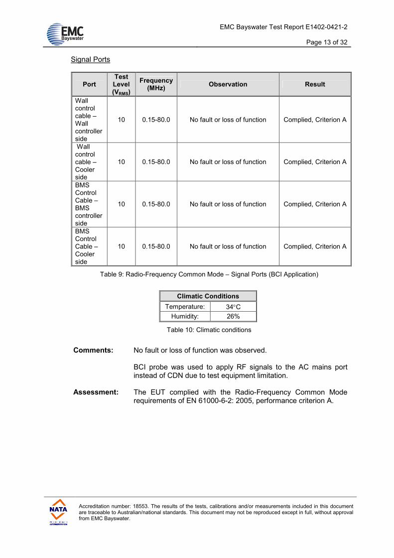
Signal Ports
Port Test Level (VRMS)
Frequency (MHz)
Observation Result
Wall control cable – Wall controller side
10 0.15-80.0 No fault or loss of function Complied, Criterion A
Wall control cable – Cooler side
10 0.15-80.0 No fault or loss of function Complied, Criterion A
BMS Control Cable – BMS controller side
10 0.15-80.0 No fault or loss of function Complied, Criterion A
BMS Control Cable – Cooler side
10 0.15-80.0 No fault or loss of function Complied, Criterion A
Table 9: Radio-Frequency Common Mode – Signal Ports (BCI Application)
Climatic Conditions
Temperature: 34°C
Humidity: 26%
Table 10: Climatic conditions
Comments: No fault or loss of function was observed.
BCI probe was used to apply RF signals to the AC mains port instead of CDN due to test equipment limitation.
Assessment: The EUT complied with the Radio-Frequency Common Mode requirements of EN 61000-6-2: 2005, performance criterion A.

EMC Bayswater Test Report E1402-0421-2
Page 14 of 32
Accreditation number: 18553. The results of the tests, calibrations and/or measurements included in this document are traceable to Australian/national standards. This document may not be reproduced except in full, without approval from EMC Bayswater.
10. Fast Transients (EN 61000-4-4)
10.1. Requirements
The EUT must comply with performance criterion B.
10.2. Test Procedure
In a shielded chamber, the EUT was placed on the ground reference plane separated by a 1.05m high metallic support. The EUT was connected and powered via the 3 phase CDN. For application to the signal ports, a capacitive coupling clamp was placed on the ground reference plane (chamber floor). The transient generator was connected to the end of the clamp nearest to the EUT. The cable of the signal port under test was placed in the capacitive coupling clamp. Transient bursts at the specified severity level were applied to the AC port and the signal ports.
The test voltage was stepped from ±1kV up to the test level on the AC power port
(±1.0kV, ±2.0kV) and signal ports (±0.5kV, ±1.0kV). The transient generator settings were as follows:
Test Voltage: ±2.0kV (AC power port), ±1.0kV (Signal ports) Rise time (Tr): 5ns Pulse width (Th): 50ns Repetition rate: 5kHz Burst duration: 15ms Burst period: 300ms Test time: 60sec per test
(Refer to photographs 43 to 45 in Appendix B for views of the test configurations)
10.3. Test Results
AC Power Port
AC Port (Mains) Test
Voltage Observation Results
L1 + L2 + L3+N+E ±1.0kV No fault or loss of function detected Complied, Criterion A
L1 + L2 + L3+N+E ±2.0kV No fault or loss of function detected Complied, Criterion A
Table 11: Fast Transients – AC Power Port
EMC Bayswater Test Report E1402-0421-2
Page 15 of 32
Accreditation number: 18553. The results of the tests, calibrations and/or measurements included in this document are traceable to Australian/national standards. This document may not be reproduced except in full, without approval from EMC Bayswater.
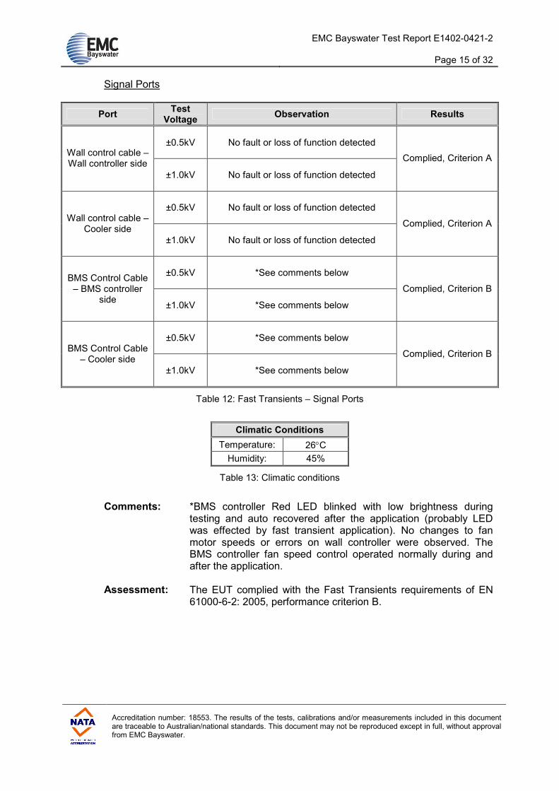
Signal Ports
Port Test
Voltage Observation Results
±0.5kV No fault or loss of function detected Wall control cable – Wall controller side
±1.0kV No fault or loss of function detected
Complied, Criterion A
±0.5kV No fault or loss of function detected Wall control cable –
Cooler side
±1.0kV No fault or loss of function detected
Complied, Criterion A
±0.5kV *See comments below BMS Control Cable
– BMS controller side
±1.0kV *See comments below
Complied, Criterion B
±0.5kV *See comments below BMS Control Cable
– Cooler side
±1.0kV *See comments below
Complied, Criterion B
Table 12: Fast Transients – Signal Ports
Climatic Conditions
Temperature: 26°C
Humidity: 45%
Table 13: Climatic conditions
Comments: *BMS controller Red LED blinked with low brightness during
testing and auto recovered after the application (probably LED was effected by fast transient application). No changes to fan motor speeds or errors on wall controller were observed. The BMS controller fan speed control operated normally during and after the application.
Assessment: The EUT complied with the Fast Transients requirements of EN 61000-6-2: 2005, performance criterion B.

EMC Bayswater Test Report E1402-0421-2
Page 16 of 32
Accreditation number: 18553. The results of the tests, calibrations and/or measurements included in this document are traceable to Australian/national standards. This document may not be reproduced except in full, without approval from EMC Bayswater.
11. Surges (EN 61000-4-5)
11.1. Requirements
The EUT must comply with performance criterion B.
11.2. Test Procedure
For testing on the AC ports, the EUT was placed on a wooden support 0.1m high, above the metal ground plane. The EUT was connected to, and powered by, the surge generator. The length of the power cable between the coupling devices and the EUT was less than 1m. In the case of a non-detachable supply cable more than 1m long, the excess length of this cable was gathered into a flat coil with a 0.4m diameter.
Surges at the specified severity level were applied to the AC Input power ports: (a) Phase - to – Neutral (Line to Line) (b) Phase – to – Phase (Line to Line) (c) Phase - to – Earth (Line to Earth) (d) Neutral - to – Earth (Line to Earth) For the signal ports, the EUT was placed on a 0.1m high insulating support on the ground plane. For unshielded cables, surges were applied to the signal port via a 0.5µF, 20mH coupling network at a distance of 2m from the EUT. The surge generator settings were as follows:
Test Voltage: ±2.0kV (line to earth) and ±1.0kV (line to line and signal ports).
Rise time (Tr): 1.2µs
Pulse width (Th): 50µs No of pulses: 10 of each polarity per test Repetition rate: 4 per minute
(Refer to photographs 46 & 47 in Appendix B for views of the test configurations)
EMC Bayswater Test Report E1402-0421-2
Page 17 of 32
Accreditation number: 18553. The results of the tests, calibrations and/or measurements included in this document are traceable to Australian/national standards. This document may not be reproduced except in full, without approval from EMC Bayswater.
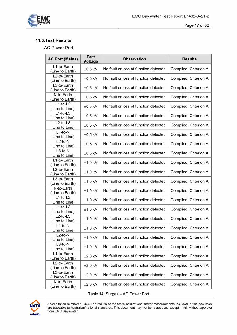
11.3. Test Results
AC Power Port
AC Port (Mains) Test
Voltage Observation Results
L1-to-Earth (Line to Earth)
±0.5 kV No fault or loss of function detected Complied, Criterion A
L2-to-Earth (Line to Earth)
±0.5 kV No fault or loss of function detected Complied, Criterion A
L3-to-Earth (Line to Earth)
±0.5 kV No fault or loss of function detected Complied, Criterion A
N-to-Earth (Line to Earth)
±0.5 kV No fault or loss of function detected Complied, Criterion A
L1-to-L2 (Line to Line)
±0.5 kV No fault or loss of function detected Complied, Criterion A
L1-to-L3 (Line to Line)
±0.5 kV No fault or loss of function detected Complied, Criterion A
L2-to-L3 (Line to Line)
±0.5 kV No fault or loss of function detected Complied, Criterion A
L1-to-N (Line to Line)
±0.5 kV No fault or loss of function detected Complied, Criterion A
L2-to-N (Line to Line)
±0.5 kV No fault or loss of function detected Complied, Criterion A
L3-to-N (Line to Line)
±0.5 kV No fault or loss of function detected Complied, Criterion A
L1-to-Earth (Line to Earth)
±1.0 kV No fault or loss of function detected Complied, Criterion A
L2-to-Earth (Line to Earth)
±1.0 kV No fault or loss of function detected Complied, Criterion A
L3-to-Earth (Line to Earth)
±1.0 kV No fault or loss of function detected Complied, Criterion A
N-to-Earth (Line to Earth)
±1.0 kV No fault or loss of function detected Complied, Criterion A
L1-to-L2 (Line to Line)
±1.0 kV No fault or loss of function detected Complied, Criterion A
L1-to-L3 (Line to Line)
±1.0 kV No fault or loss of function detected Complied, Criterion A
L2-to-L3 (Line to Line)
±1.0 kV No fault or loss of function detected Complied, Criterion A
L1-to-N (Line to Line)
±1.0 kV No fault or loss of function detected Complied, Criterion A
L2-to-N (Line to Line)
±1.0 kV No fault or loss of function detected Complied, Criterion A
L3-to-N (Line to Line)
±1.0 kV No fault or loss of function detected Complied, Criterion A
L1-to-Earth (Line to Earth)
±2.0 kV No fault or loss of function detected Complied, Criterion A
L2-to-Earth (Line to Earth)
±2.0 kV No fault or loss of function detected Complied, Criterion A
L3-to-Earth (Line to Earth)
±2.0 kV No fault or loss of function detected Complied, Criterion A
N-to-Earth (Line to Earth)
±2.0 kV No fault or loss of function detected Complied, Criterion A
Table 14: Surges – AC Power Port

EMC Bayswater Test Report E1402-0421-2
Page 18 of 32
Accreditation number: 18553. The results of the tests, calibrations and/or measurements included in this document are traceable to Australian/national standards. This document may not be reproduced except in full, without approval from EMC Bayswater.
Signal Ports
Port Test
Voltage Observation Results
±0.5kV No fault or loss of function detected Wall control cable – Wall controller side
±1.0kV No fault or loss of function detected
Complied, Criterion A
±0.5kV No fault or loss of function detected Wall control cable –
Cooler side
±1.0kV No fault or loss of function detected
Complied, Criterion A
±0.5kV No fault or loss of function detected BMS Control Cable
– BMS controller side
±1.0kV No fault or loss of function detected
Complied, Criterion A
±0.5kV No fault or loss of function detected BMS Control Cable
– Cooler side
±1.0kV No fault or loss of function detected
Complied, Criterion A
Table 15: Surges – Signal Ports
Climatic Conditions
Temperature: 26°C
Humidity: 45%
Table 16: Climatic conditions
Comments: No fault or loss of function was observed.
Assessment: The EUT complied with the Surges immunity requirements of EN 61000-6-2: 2005, performance criterion A.

EMC Bayswater Test Report E1402-0421-2
Page 19 of 32
Accreditation number: 18553. The results of the tests, calibrations and/or measurements included in this document are traceable to Australian/national standards. This document may not be reproduced except in full, without approval from EMC Bayswater.
12. Voltage Dips and Interruptions (EN 61000-4-11)
12.1. Requirements
The EUT must comply with performance criterion B for voltage dips of 0% residual voltage for 1 cycle. The EUT must comply with performance criterion C, for voltage dips of 40% residual voltage for 10 cycles, voltages dips of 70% residual voltage for 25 cycles and voltage interruptions of 0% residual voltage for 250 cycles.
12.2. Test Procedure
The EUT was placed on a wooden table 0.8m high, above the metal ground plane. The EUT was connected to, and powered by, the test generator. The length of the power cable between the coupling devices and the EUT was less than 1m. In the case of a non-detachable supply cable more than 1m long, the excess length of this cable was gathered into a flat coil with a 0.4m diameter. Voltage dips of 0% residual voltage for 1 period (20ms), 40% residual voltage for 10 cycles (200ms) and 70% residual voltage for 25 cycles (500ms) were applied to the AC power port. Voltage interruptions of 0% residual voltage for 250 cycles, (5000ms) were applied to the AC power port. (Refer to photograph 48 in Appendix B for a view of the test configuration)
12.3. Test Results
Type Test
Specification Observation Results
Voltage Dip 0% Residual
voltage, 1 cycle
No fault or loss of function detected Complied, Criterion A
Voltage Dip 40% Residual
voltage, 10 cycles
No fault or loss of function detected Complied, Criterion A
Voltage Dip 70% Residual
voltage, 25 cycles
No fault or loss of function detected Complied, Criterion A
Voltage Interruption
0% Residual voltage, 250
cycles Manual restart required Complied, Criterion C
Table 17: Voltage Dips and Interruptions
Climatic Conditions
Temperature: 36°C
Humidity: 28%
Table 18: Climatic conditions
EMC Bayswater Test Report E1402-0421-2
Page 20 of 32
Accreditation number: 18553. The results of the tests, calibrations and/or measurements included in this document are traceable to Australian/national standards. This document may not be reproduced except in full, without approval from EMC Bayswater.
Comments: The EUT turned off during the voltage interruption application
and required manual restart. After the interruption performance returned to normal, thus complying with performance criterion C. Voltage dips were applied on phase to neutral (one at a time) only. Voltage interruptions were applied to all three phases simultaneously. Phase to phase voltage dips were not applied due to test equipment limitation.
Assessment: The EUT complied with the Voltage Dips requirements of EN 61000-6-2: 2005, performance criterion A and the Voltage Interruptions requirements of EN 61000-6-2: 2005, performance criterion C.
13. Conclusion
The modified Seeley International Pty Ltd, ENV, Fixed Evaporative Air Cooler complied with the applicable requirements of EN 61000-6-2: 2005.
EMC Bayswater Test Report E1402-0421-2
Page 21 of 32
Accreditation number: 18553. The results of the tests, calibrations and/or measurements included in this document are traceable to Australian/national standards. This document may not be reproduced except in full, without approval from EMC Bayswater.
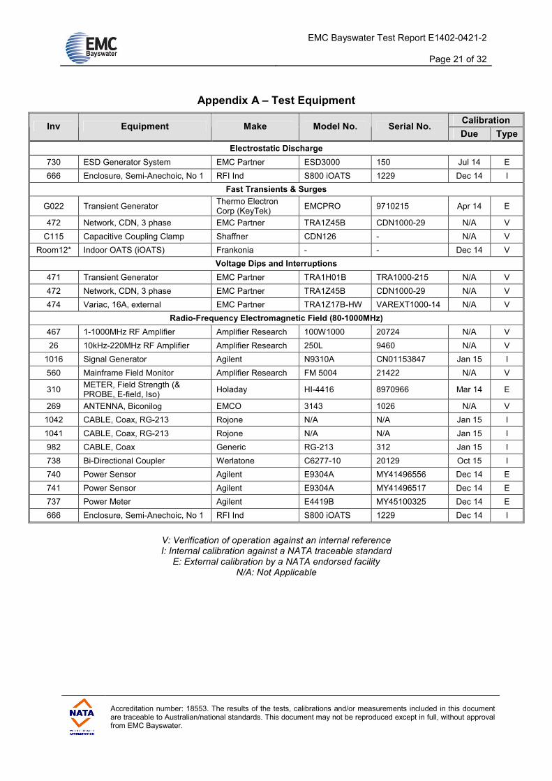
Appendix A – Test Equipment
Calibration Inv Equipment Make Model No. Serial No.
Due Type
Electrostatic Discharge
730 ESD Generator System EMC Partner ESD3000 150 Jul 14 E
666 Enclosure, Semi-Anechoic, No 1 RFI Ind S800 iOATS 1229 Dec 14 I
Fast Transients & Surges
G022 Transient Generator Thermo Electron Corp (KeyTek)
EMCPRO 9710215 Apr 14 E
472 Network, CDN, 3 phase EMC Partner TRA1Z45B CDN1000-29 N/A V
C115 Capacitive Coupling Clamp Shaffner CDN126 - N/A V
Room12* Indoor OATS (iOATS) Frankonia - - Dec 14 V
Voltage Dips and Interruptions
471 Transient Generator EMC Partner TRA1H01B TRA1000-215 N/A V
472 Network, CDN, 3 phase EMC Partner TRA1Z45B CDN1000-29 N/A V
474 Variac, 16A, external EMC Partner TRA1Z17B-HW VAREXT1000-14 N/A V
Radio-Frequency Electromagnetic Field (80-1000MHz)
467 1-1000MHz RF Amplifier Amplifier Research 100W1000 20724 N/A V
26 10kHz-220MHz RF Amplifier Amplifier Research 250L 9460 N/A V
1016 Signal Generator Agilent N9310A CN01153847 Jan 15 I
560 Mainframe Field Monitor Amplifier Research FM 5004 21422 N/A V
310 METER, Field Strength (& PROBE, E-field, Iso)
Holaday HI-4416 8970966 Mar 14 E
269 ANTENNA, Biconilog EMCO 3143 1026 N/A V
1042 CABLE, Coax, RG-213 Rojone N/A N/A Jan 15 I
1041 CABLE, Coax, RG-213 Rojone N/A N/A Jan 15 I
982 CABLE, Coax Generic RG-213 312 Jan 15 I
738 Bi-Directional Coupler Werlatone C6277-10 20129 Oct 15 I
740 Power Sensor Agilent E9304A MY41496556 Dec 14 E
741 Power Sensor Agilent E9304A MY41496517 Dec 14 E
737 Power Meter Agilent E4419B MY45100325 Dec 14 E
666 Enclosure, Semi-Anechoic, No 1 RFI Ind S800 iOATS 1229 Dec 14 I
V: Verification of operation against an internal reference I: Internal calibration against a NATA traceable standard E: External calibration by a NATA endorsed facility
N/A: Not Applicable

EMC Bayswater Test Report E1402-0421-2
Page 22 of 32
Accreditation number: 18553. The results of the tests, calibrations and/or measurements included in this document are traceable to Australian/national standards. This document may not be reproduced except in full, without approval from EMC Bayswater.
Calibration Inv Equipment Make Model No. Serial No.
Due Type
Radio-Frequency Electromagnetic Field (1.4-2.7GHz)
737 Power Meter Agilent E4419B MY45100325 Dec 14 E
740 Power Sensor Agilent E9304A MY41496556 Dec 14 E
1127 Amplifier, RF, power IFI S31-100 R1705 1213 N/A V
209 ANTENNA, Double Ridge Horn EMCO 3115 9210-3945 Aug 15 I
1016 Signal Generator Agilent N9310A CN01153847 Jan 15 I
501 E-Field Probe Holaday HI-4450 96627 Aug 14 E
560 Mainframe Field Monitor Amplifier Research FM 5004 21422 N/A V
666 Enclosure, Semi-Anechoic, No 1 RFI Ind S800 iOATS 1229 Dec 14 I
600 COUPLER, Coax, Bi-directional Narda 3022 10096 May 14 I
942 ATTENUATOR, 20dB JFW 50FPE-020 N/A Aug 14 I
943 ATTENUATOR, 20dB JFW 50FPE-020 N/A Aug 14 I
989 CABLE, Coax, Sucoflex 104A Huber+Suhner 44454/4A 44454/4A Jan 15 I
1039 CABLE, Coax, RG-214 Huber+Suhner N/A N/A Jan 15 I
1040 CABLE, Coax, RG-213 RFI N/A N/A Jan 15 I
Radio-Frequency Common Mode
636 GENERATOR, Signal, RF Gigatronics (Fluke) 6080A 5465602 Jan 15 I
583 Amplifier, RF, power ENI 3200L 127 N/A V
737 Power Meter, Dual Agilent E4419B MY45100325 Dec 14 E
214 Bi-Directional Coupler Amplifier Research DC2000 12090 May 14 I
740 Power Sensor Agilent E9304A MY41496556 Dec 14 E
994 CABLE, Coax Huber+Suhner RG-214/U C004 Jan 15 I
993 CABLE, Coax, 1m Belden RG-213 C016 Jan 15 I
992 CABLE, Coax, 1m Belden RG-213 C001 Jan 15 I
656 Bulk Current Injection Probe FCC F-120-3 101 N/A V
65 Probe, Current, RF Solar 6741-1 8020-21 Oct 16 I
981 CABLE, Coax, 1m Huber+Suhner HSA95465/2800 0082 Jan 14 I
945 Attenuator 6dB JFW 50FH-006-300 0703 Jan 16 I
667 Shielded Enclosure #1 RFI Industries S800 1201 N/A V
General Equipment
997 HYGROMETER, Temp, Humidity
RS 408 6109 Mar 14 E
V: Verification of operation against an internal reference I: Internal calibration against a NATA traceable standard E: External calibration by a NATA endorsed facility
N/A: Not Applicable

EMC Bayswater Test Report E1402-0421-2
Page 23 of 32
Accreditation number: 18553. The results of the tests, calibrations and/or measurements included in this document are traceable to Australian/national standards. This document may not be reproduced except in full, without approval from EMC Bayswater.
Appendix B – Photographs
Number Photograph Description
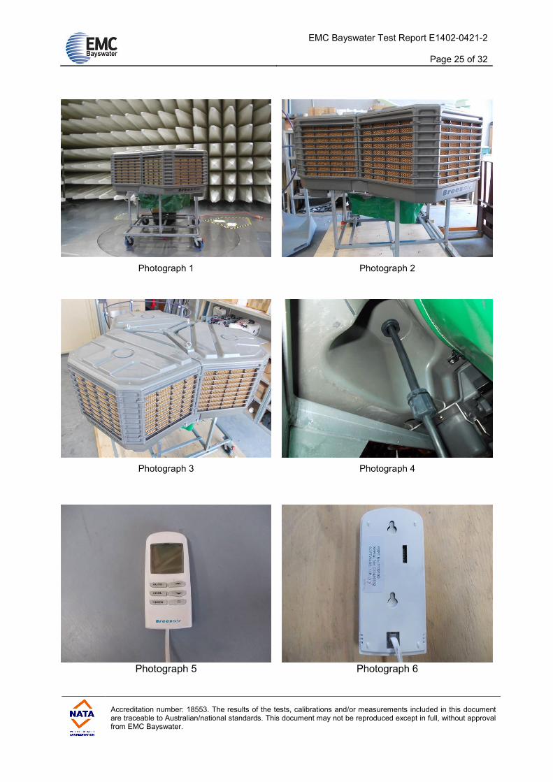
1
2
3
4
EUT – ENV Cooler – External views
5
6
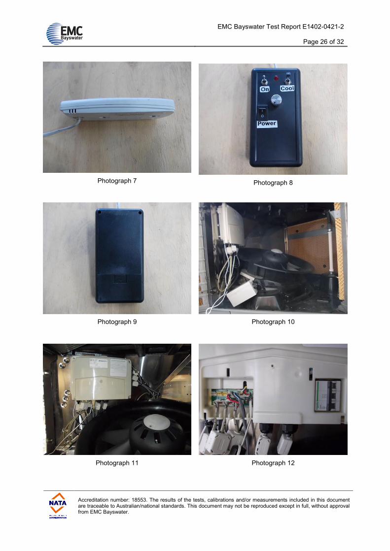
7
EUT – Wall controller – External views
8
9 EUT – BMS controller – External views
10
11
12
13
14
15
16
EUT – ENV Cooler – Internal views
17
18 EUT – Wall controller – Internal views
19
20 EUT – BMS controller – Internal views
21
22 EUT – ENV Cooler – Identification labels
23
24
25
EUT – ENV Cooler – Fan motors (3 motors) - Identification labels
26 EUT – Wall controller – Identification label
27 Radio-frequency Electromagnetic Field – Test configuration – EUT front
28 Radio-frequency Electromagnetic Field – Test configuration – EUT right side
29 Radio-frequency Electromagnetic Field – Test configuration – Below 1GHz
30 Radio-frequency Electromagnetic Field – Test configuration – Above 1GHz
31 ESD – Test configuration – Indirect application – HCP
32
33 ESD – Test configuration – Indirect application – VCP
34 ESD – Test configuration – Direct application – Contact discharge
35 ESD – Test configuration – Direct application – Air discharge
36 ESD –Direct application – Contact discharge – Test points
37
38
39
ESD – Direct application – Air discharge – Test points
EMC Bayswater Test Report E1402-0421-2
Page 24 of 32
Accreditation number: 18553. The results of the tests, calibrations and/or measurements included in this document are traceable to Australian/national standards. This document may not be reproduced except in full, without approval from EMC Bayswater.
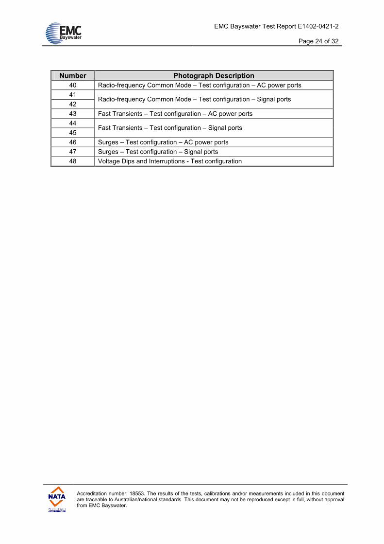
Number Photograph Description
40 Radio-frequency Common Mode – Test configuration – AC power ports
41
42 Radio-frequency Common Mode – Test configuration – Signal ports
43 Fast Transients – Test configuration – AC power ports
44
45 Fast Transients – Test configuration – Signal ports
46 Surges – Test configuration – AC power ports
47 Surges – Test configuration – Signal ports
48 Voltage Dips and Interruptions - Test configuration
EMC Bayswater Test Report E1402-0421-2
Page 25 of 32
Accreditation number: 18553. The results of the tests, calibrations and/or measurements included in this document are traceable to Australian/national standards. This document may not be reproduced except in full, without approval from EMC Bayswater.
Photograph 1
Photograph 2
Photograph 3
Photograph 4
Photograph 5
Photograph 6
EMC Bayswater Test Report E1402-0421-2
Page 26 of 32
Accreditation number: 18553. The results of the tests, calibrations and/or measurements included in this document are traceable to Australian/national standards. This document may not be reproduced except in full, without approval from EMC Bayswater.
Photograph 7
Photograph 8
Photograph 9
Photograph 10
Photograph 11
Photograph 12

EMC Bayswater Test Report E1402-0421-2
Page 27 of 32
Accreditation number: 18553. The results of the tests, calibrations and/or measurements included in this document are traceable to Australian/national standards. This document may not be reproduced except in full, without approval from EMC Bayswater.
Photograph 13
Photograph 14
Photograph 15
Photograph 16
Photograph 17
Photograph 18

EMC Bayswater Test Report E1402-0421-2
Page 28 of 32
Accreditation number: 18553. The results of the tests, calibrations and/or measurements included in this document are traceable to Australian/national standards. This document may not be reproduced except in full, without approval from EMC Bayswater.
Photograph 19
Photograph 20
Photograph 21
Photograph 22
Photograph 23
Photograph 24

EMC Bayswater Test Report E1402-0421-2
Page 29 of 32
Accreditation number: 18553. The results of the tests, calibrations and/or measurements included in this document are traceable to Australian/national standards. This document may not be reproduced except in full, without approval from EMC Bayswater.
Photograph 25
Photograph 26
Photograph 27
Photograph 28
Photograph 29
Photograph 30

EMC Bayswater Test Report E1402-0421-2
Page 30 of 32
Accreditation number: 18553. The results of the tests, calibrations and/or measurements included in this document are traceable to Australian/national standards. This document may not be reproduced except in full, without approval from EMC Bayswater.
Photograph 31
Photograph 32
Photograph 33
Photograph 34
Photograph 35
Photograph 36

EMC Bayswater Test Report E1402-0421-2
Page 31 of 32
Accreditation number: 18553. The results of the tests, calibrations and/or measurements included in this document are traceable to Australian/national standards. This document may not be reproduced except in full, without approval from EMC Bayswater.
Photograph 37
Photograph 38
Photograph 39
Photograph 40
Photograph 41
Photograph 42

EMC Bayswater Test Report E1402-0421-2
Page 32 of 32
Accreditation number: 18553. The results of the tests, calibrations and/or measurements included in this document are traceable to Australian/national standards. This document may not be reproduced except in full, without approval from EMC Bayswater.
Photograph 43
Photograph 44
Photograph 45
Photograph 46
Photograph 47
Photograph 48