emc and circuit protection solution for led driver · pdf file¾the inrush current...
TRANSCRIPT

SunlordEXPERT IN PASSIVE PARTS
EMC and Circuit Protection Solution EMC and Circuit Protection Solution For LED Driver CircuitFor LED Driver Circuit
• Jun 7th, 2011
SunlordEXPERT IN PASSIVE PARTSContentContent
1.1. Requirement of components in LED driver circuit Requirement of components in LED driver circuit
2.2. EMC and circuit protection solution for LED driver EMC and circuit protection solution for LED driver circuitcircuit
3.3. SunlordSunlord related product presentationrelated product presentationChip VaristorChip NTC Chip NTC thermistorthermistorChip ferrite beadChip power inductorChip solid tantalum capacitor

SunlordEXPERT IN PASSIVE PARTS
Large PowerLarge Power
High EfficientHigh Efficient
Low ProfileLow Profile
Large CurrentLarge Current
Small sizeSmall size
Requirement of Components in LED Driver Circuit Requirement of Requirement of CComponents in LED omponents in LED DDriver river CCircuit ircuit
Large InductanceLarge Inductance
High ReliabilityHigh Reliability
Low DCRLow DCR
EMC/ESD CapabilityEMC/ESD Capability
LED Driver circuitLED Driver circuit ComponentsComponents
Low RippleLow Ripple
EMC Capability EMC Capability
High ReliabilityHigh Reliability

SunlordEXPERT IN PASSIVE PARTSContentContent
1.1. Requirement of components in LED driver circuitRequirement of components in LED driver circuit
2.2. EMC and circuit protection solution for LED driver EMC and circuit protection solution for LED driver circuitcircuit
3.3. SunlordSunlord related product presentationrelated product presentationChip VaristorChip NTC Chip NTC thermistorthermistorChip ferrite beadChip power inductorChip solid tantalum capacitor

SunlordEXPERT IN PASSIVE PARTS
LED Driver Circuit LED Driver Circuit
LED LightingLED Lighting
Surge Suppression
Circuit
DC-DC Converter
TCM
1
4
5
Filtering Circuit
2
Filtering Circuit
3
AC-DC BridgeRectifiers
AC-DC BridgeRectifiers
AC PowerAC Power
PFC CircuitPFC Circuit

SunlordEXPERT IN PASSIVE PARTSEMC EMC aand nd CCircuit ircuit PProtection rotection SSolutionolution
SWPAPower InductorEnergy StoringL4
Tantalum Capacitor
NTC Thermistor
Bead/Power inductorPower NTC Thermistor
Varistor for Surge Protection
Series
TC211/212Energy StoringC1
SDNTTemp. SensingRt2
Bead/SWPAFilteringL1,L2,L3SPNTSurge ProtectionRt1
SDVL/SDV Series
Surge ProtectionRvP/NFunctionNo.
SunlordEXPERT IN PASSIVE PARTS
1.1. Requirement of components in LED driver circuitRequirement of components in LED driver circuit
2.2. EMC and circuit protection solution for LED driver EMC and circuit protection solution for LED driver circuitcircuit
3.3. SunlordSunlord related product presentationrelated product presentationChip Chip VaristorVaristorChip NTC Chip NTC ThermistorThermistorChip Ferrite BeadChip Power InductorChip Solid Tantalum Capacitor
ContentContent

SunlordEXPERT IN PASSIVE PARTSVaristorVaristor
Internal Electrode
Varistor is made of ZnO ceramics which have good performance of fast response time (less than 0.5ns), transmit energy absorbing and transferring to ground with millions of series-parallel P-N junctions.
Features:Fast response time: < 0.5nS High surge current capabilityLow leakage currentLow clamping voltageBidirectional V/I characteristic
V-I CharacteristicsMicrostructure
P-N Junction
Crystal Grain
Crystal
Boundary

SunlordEXPERT IN PASSIVE PARTSWorking principle of Working principle of VaristorVaristor
Conduction/ Radiation
8/20μSWaveμS level
Lightning discharges generate a wide range of electromagnetic radiations. The equipments will be damaged due to high transient voltage by induction or conduction.
TransmissionsSimulation WaveDuration
System rated voltage
OvervoltageWithstand Voltage
Signal /Power
Ground
ICVaristor
Vdc
Clamping Voltage Clamping Voltage

SunlordEXPERT IN PASSIVE PARTS
AC AC-DC DC-DC DriverIC
LED
1 2 3 4
Applications of Applications of VaristorVaristor for LED Driverfor LED Driver
ESD protection for LEDs
Secondary protection: suppress Induced & switching over-voltage, protecting DC-DC Module and driver IC (good replacement of SMAJ/SMBJ TVS)
Primary protection: suppress Induced over-voltage cased by power and lightning
Function
Cp=10~360pfSDV1005/1608/20124
Primary Electrical Parameter
Sunlord VaristorNo.
Vc=40V, Ip=120~400A, Et=0.4~2.3J
SDV3216/32252/3
Vc=775V、Ip=400A、Et=13.4J
SDVL5650KA301PTF1
SunlordEXPERT IN PASSIVE PARTS
1.1. Requirement of components in LED driver circuitRequirement of components in LED driver circuit
2.2. EMC and circuit protection solution for LED driver EMC and circuit protection solution for LED driver circuitcircuit
3.3. SunlordSunlord related product presentationrelated product presentationChip Chip VaristorVaristorChip NTC Chip NTC ThermistorThermistorChip Ferrite BeadChip Power InductorChip Solid Tantalum Capacitor
ContentContent
SunlordEXPERT IN PASSIVE PARTSChip NTC Chip NTC ThermistorThermistor
R25
R50
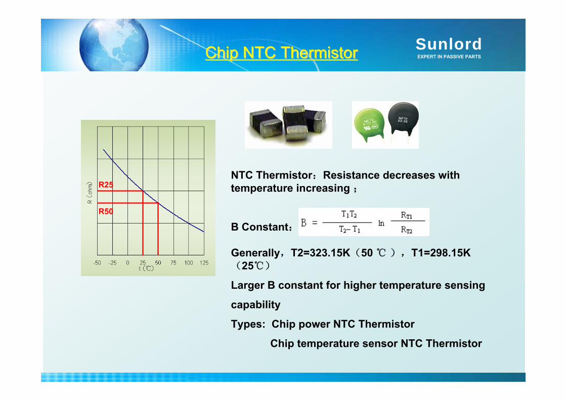
NTC Thermistor:Resistance decreases with temperature increasing ;
B Constant:
Generally,T2=323.15K(50 ),T1=298.15K(25)
Larger B constant for higher temperature sensing
capability
Types: Chip power NTC Thermistor
Chip temperature sensor NTC Thermistor
SunlordEXPERT IN PASSIVE PARTS
Chip Power NTC Chip Power NTC ThermistorThermistor
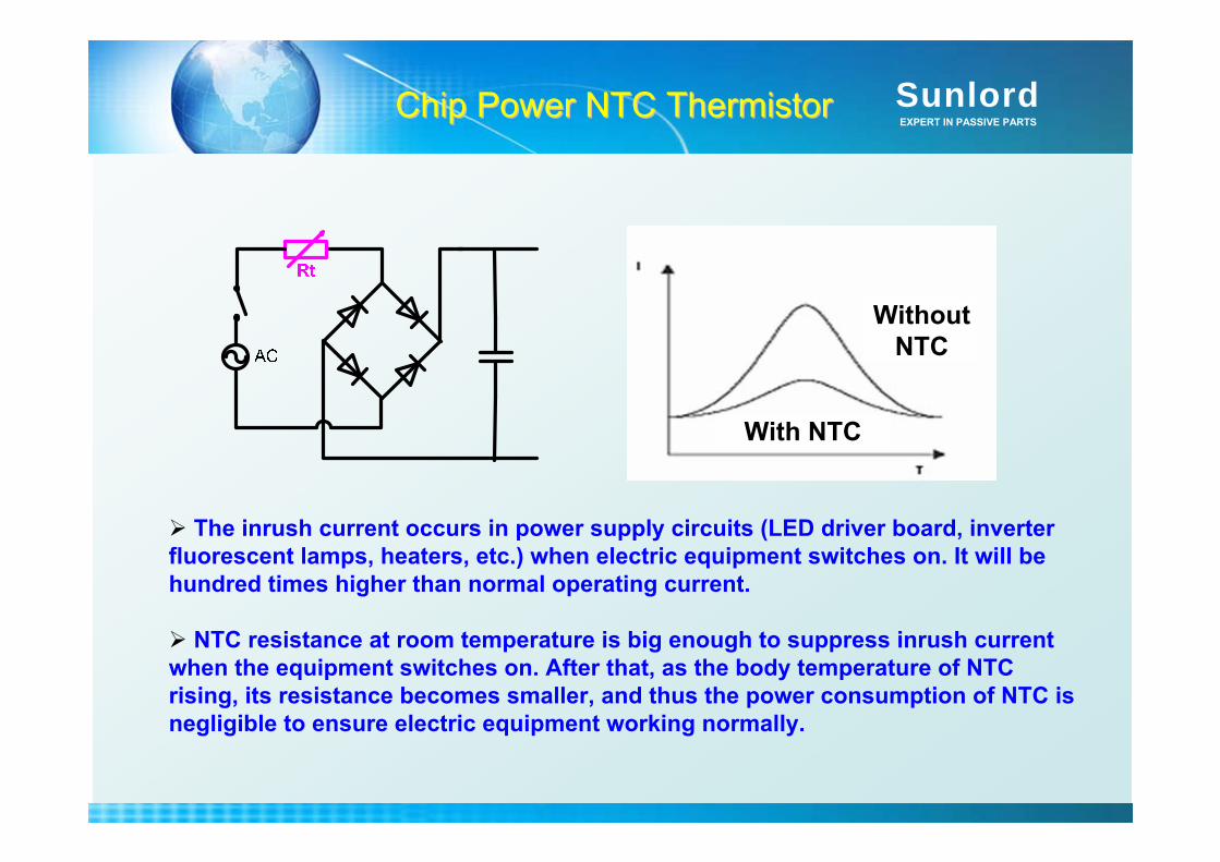
The inrush current occurs in power supply circuits (LED driver board, inverter fluorescent lamps, heaters, etc.) when electric equipment switches on. It will be hundred times higher than normal operating current.
NTC resistance at room temperature is big enough to suppress inrush current when the equipment switches on. After that, as the body temperature of NTC rising, its resistance becomes smaller, and thus the power consumption of NTC is negligible to ensure electric equipment working normally.
With NTC
Without NTC
SunlordEXPERT IN PASSIVE PARTS
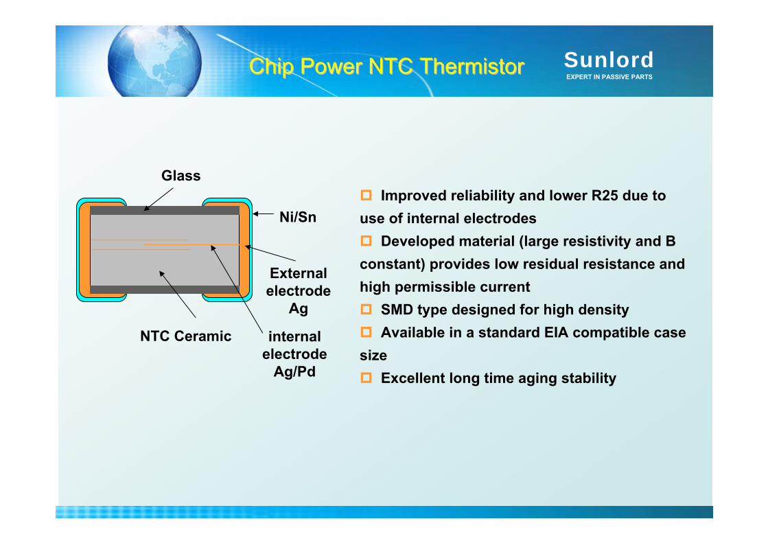
External electrode
Ag
internal electrode
Ag/Pd
NTC Ceramic
Ni/Sn
GlassImproved reliability and lower R25 due to
use of internal electrodesDeveloped material (large resistivity and B
constant) provides low residual resistance and high permissible current
SMD type designed for high densityAvailable in a standard EIA compatible case
sizeExcellent long time aging stability
Chip Power NTC Chip Power NTC ThermistorThermistor

SunlordEXPERT IN PASSIVE PARTS
Excellent Performance of Chip Excellent Performance of Chip Power NTCPower NTC
The material resistivity of Pin-type is very low (50-200m·mΩ) which results in low B constant and high Residual Resistance.
Chip power NTC adopts innovative materials with high resistivity (5000m · mΩ
or so) and internal electrode structure, and thus provides high B constant (4000K or more) and low Residual Resistance.
0.14-0.70.16-0.93500-40002500-300010080Φ20
0.14-1.30.17-2.43500-40002500-30008063Φ15
0.14-1.30.17-2.43500-40002500-33005056/8063Φ13
0.14-1.30.19-33500-40002500-33005056Φ11
0.14-130.21-303500-40002500-33004532/5056Φ9
0.14-7.90.283-11.653500-40002500-33004532Φ7
0.14-7.90.353-18.73500-40002500-33004516Φ5
ChipPin-typeChipPin-typeChip(L×W)
Pin-type(diameter)
Residual Resistance (Ω)B constant(K)Size
SunlordEXPERT IN PASSIVE PARTS
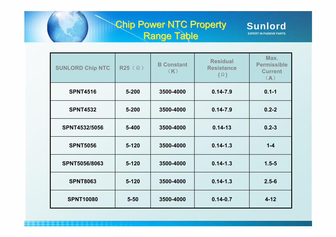
Chip Power NTC Property Chip Power NTC Property Range TableRange Table
4-120.14-0.73500-40005-50SPNT10080
2.5-60.14-1.33500-40005-120SPNT8063
1.5-50.14-1.33500-40005-120SPNT5056/8063
1-40.14-1.33500-40005-120SPNT5056
0.2-30.14-133500-40005-400SPNT4532/5056
0.2-20.14-7.93500-40005-200SPNT4532
0.1-10.14-7.93500-40005-200SPNT4516
Max. Permissible
Current(A)
Residual Resistance
(Ω)
B Constant(K)
R25(Ω)SUNLORD Chip NTC
SunlordEXPERT IN PASSIVE PARTS
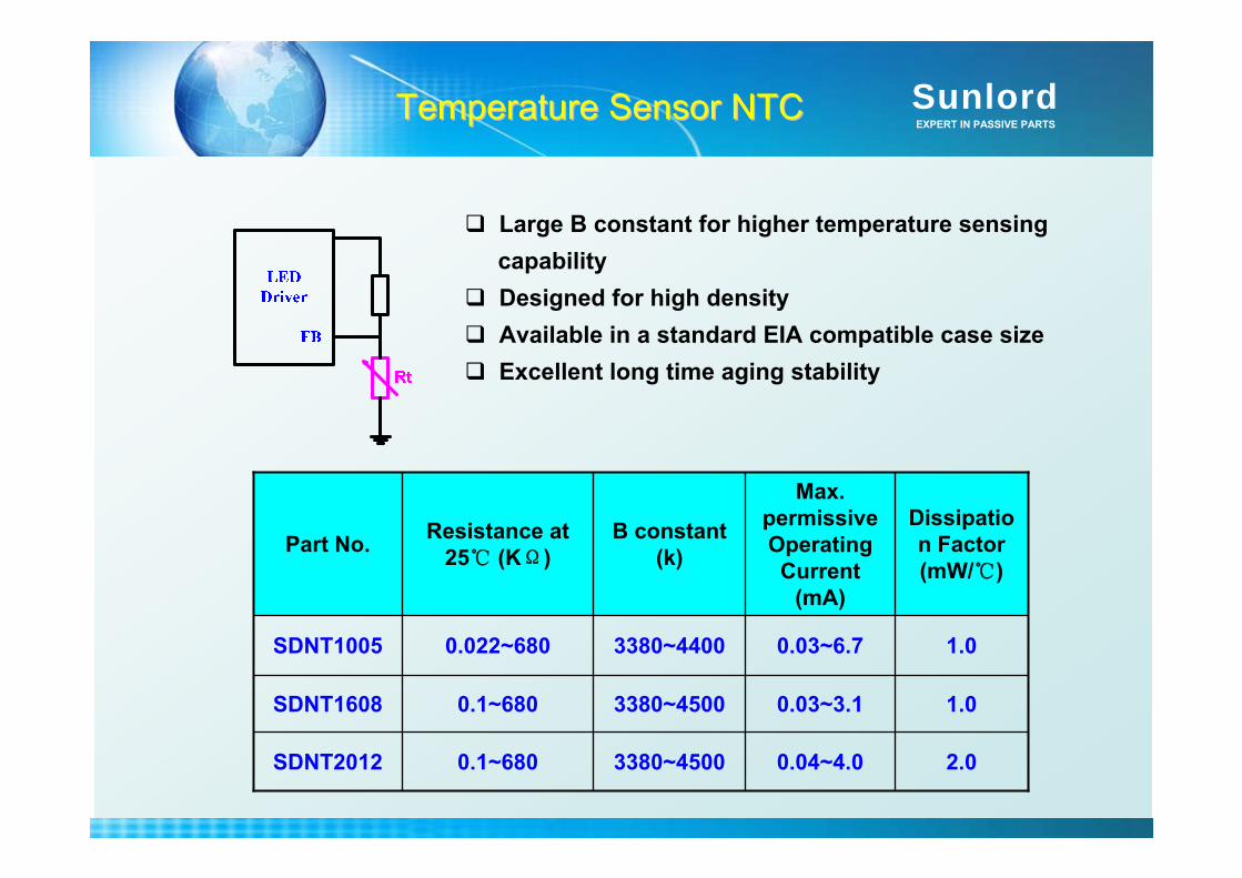
Temperature Sensor NTCTemperature Sensor NTC
2.00.04~4.03380~45000.1~680SDNT2012
1.00.03~3.13380~45000.1~680SDNT1608
1.00.03~6.73380~44000.022~680SDNT1005
Dissipation Factor (mW/)
Max. permissive Operating Current
(mA)
B constant (k)
Resistance at 25 (KΩ)Part No.
Large B constant for higher temperature sensing capabilityDesigned for high densityAvailable in a standard EIA compatible case sizeExcellent long time aging stability
SunlordEXPERT IN PASSIVE PARTS
1.1. Requirement of components in LED driver circuitRequirement of components in LED driver circuit
2.2. EMC and circuit protection solution for LED driver EMC and circuit protection solution for LED driver circuitcircuit
3.3. SunlordSunlord related product presentationrelated product presentationChip Chip VaristorVaristorChip NTC Chip NTC ThermistorThermistorChip Ferrite BeadChip Ferrite BeadChip Power InductorChip Solid Tantalum Capacitor
ContentContent

SunlordEXPERT IN PASSIVE PARTS
Ferrite Bead Working Theory
Bead is connected in series in the circuit. Bead is a frequency dependent resistor. At low frequencies, inductive impedance is low.At higher frequencies, the impedance increases and becomes
resistive function .The resistive loss attenuates the unwanted frequencies
through heating of the bead’s ferrite material due to eddy currents.
Equivalent CircuitZ=R+jX
Z2=R2+X2
L0
R0
C0

SunlordEXPERT IN PASSIVE PARTSFerrite Bead Future DevelopmentFerrite Bead Future Development
Development PlanDevelopment Plan
Wide Frequency Range
EMI tends to higher frequency with the development of high speed transmission. Good EMC capability in high frequency beads are needed. Sunlord HZ/HPZ series bead are effective in suppressing high frequency EMI in 30MHz~3GHz.
Development plan:Bead for 6GHz and above EMI suppression
Large Current
Sunlord large current bead PZ/UPZ series which provide large rated current and low RDC achieve low heat loss in power supply circuit.
Development plan: large current of >10A
Miniaturization
Smaller size beads are required due to limited surface of LED lightings
Main size: 2012/1608
Tendency:→1005 → 0603 →…
High impedanceHigh impedance is also a tendency in order to achieve a better EMC performance.
The highest impedance bead nowadays of Sunlord’s is 2700Ω@100MHz.
SunlordEXPERT IN PASSIVE PARTSSunlordSunlord’’ss BeadsBeads
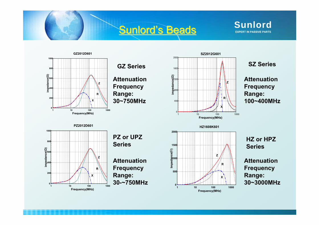
GZ Series SZ Series
1 10 100 1000Frequency(MHz)
0
200
400
600
800
1000
impe
danc
e(Ω
)
GZ2012D601
X
R
Z
1 10 100 1000Frequency(MHz)
0
400
800
1200
1600
2000
impe
danc
e(Ω
)
SZ2012G601
X
Z
R
Attenuation Frequency Range: 30~750MHz
Attenuation Frequency Range: 100~400MHz
PZ or UPZ Series
HZ or HPZ Series
1 10 100 1000Frequency(MHz)
0
500
1000
1500
2000
Impe
danc
e(Ω
)
X
Z
R
HZ1608K601
Attenuation Frequency Range:30-~750MHz
Attenuation Frequency Range: 30~3000MHz
1 10 100 1000Frequency(MHz)
0
200
400
600
800
1000
impe
danc
e(Ω
)
PZ2012D601
X
R
Z
SunlordEXPERT IN PASSIVE PARTS
Ir Range(A)
Impedance Range(Ω)
Ir Range(A)
Impedance Range(Ω)
Ir Range(A)
Impedance Range(Ω)
Ir Range(A)
Impedance Range(Ω)
Ir Range(A)
Impedance Range(Ω)
Ir Range(A)
Impedance Range(Ω)
Ir Range(A)
Impedance Range(Ω)
/
……
……
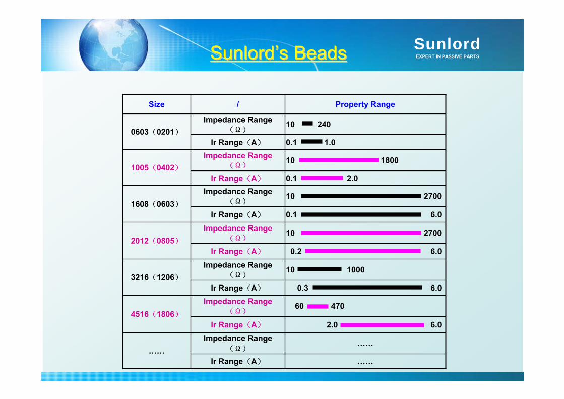
2.0 6.0
60 470
0.3 6.0
10 1000
0.2 6.0
10 2700
0.1 6.0
10 2700
0.1 2.0
10 1800
0.1 1.0
10 240
Property Range
2012(0805)
1005(0402)
4516(1806)
……
3216(1206)
1608(0603)
0603(0201)
Size
SunlordSunlord’’ss BeadsBeads
SunlordEXPERT IN PASSIVE PARTS
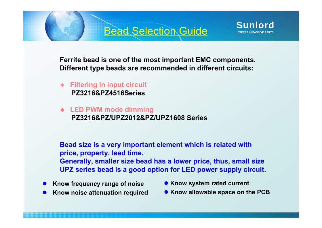
Ferrite bead is one of the most important EMC components.Different type beads are recommended in different circuits:
Filtering in input circuitPZ3216&PZ4516Series
LED PWM mode dimmingPZ3216&PZ/UPZ2012&PZ/UPZ1608 Series
Bead Selection Guide
Bead size is a very important element which is related with price, property, lead time. Generally, smaller size bead has a lower price, thus, small sizeUPZ series bead is a good option for LED power supply circuit.
Know frequency range of noiseKnow noise attenuation required
Know system rated currentKnow allowable space on the PCB

SunlordEXPERT IN PASSIVE PARTS
1.1. Requirement of components in LED driver circuitRequirement of components in LED driver circuit
2.2. EMC and circuit protection solution for LED driver EMC and circuit protection solution for LED driver circuitcircuit
3.3. SunlordSunlord related product presentationrelated product presentationChip Chip VaristorVaristorChip NTC Chip NTC ThermistorThermistorChip Ferrite BeadChip Power InductorChip Power InductorChip Solid Tantalum Capacitor
ContentContent
SunlordEXPERT IN PASSIVE PARTS
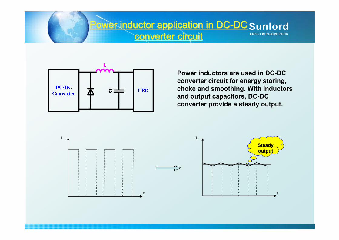
Power inductor application in DCPower inductor application in DC--DC DC converter circuitconverter circuit
t
I
t
I
Power inductors are used in DC-DC converter circuit for energy storing, choke and smoothing. With inductors and output capacitors, DC-DC converter provide a steady output.
Steady output
SunlordEXPERT IN PASSIVE PARTS
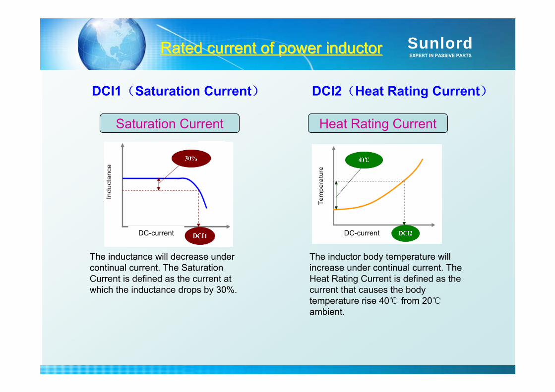
DCI1(Saturation Current) DCI2(Heat Rating Current)
Saturation Current Heat Rating Current
The inductor body temperature will increase under continual current. The Heat Rating Current is defined as the current that causes the body temperature rise 40 from 20ambient.
The inductance will decrease under continual current. The Saturation Current is defined as the current at which the inductance drops by 30%.
Rated current of power inductorRated current of power inductor
DC-current DC-current

SunlordEXPERT IN PASSIVE PARTS
SWPA Series Structure Conventional Structure
SWPA structure makes the lowest profile power inductor possible, offers an excellent combination of high current , high inductance and low DC resistance.
Unique Compact Component Structure Unique Compact Component Structure

SunlordEXPERT IN PASSIVE PARTS
Sleeve type: The air gap between magnetic ring and core forms single and big.
Resin
Ferrite Grain
Air Gap
电线 磁芯 磁环
气隙
Wire Ferrite Core Ring Core
Air Cap
SWPA: The air gaps between magnetic powders form uniform and multiple.
Unique Compact Component Structure Unique Compact Component Structure
SunlordEXPERT IN PASSIVE PARTS
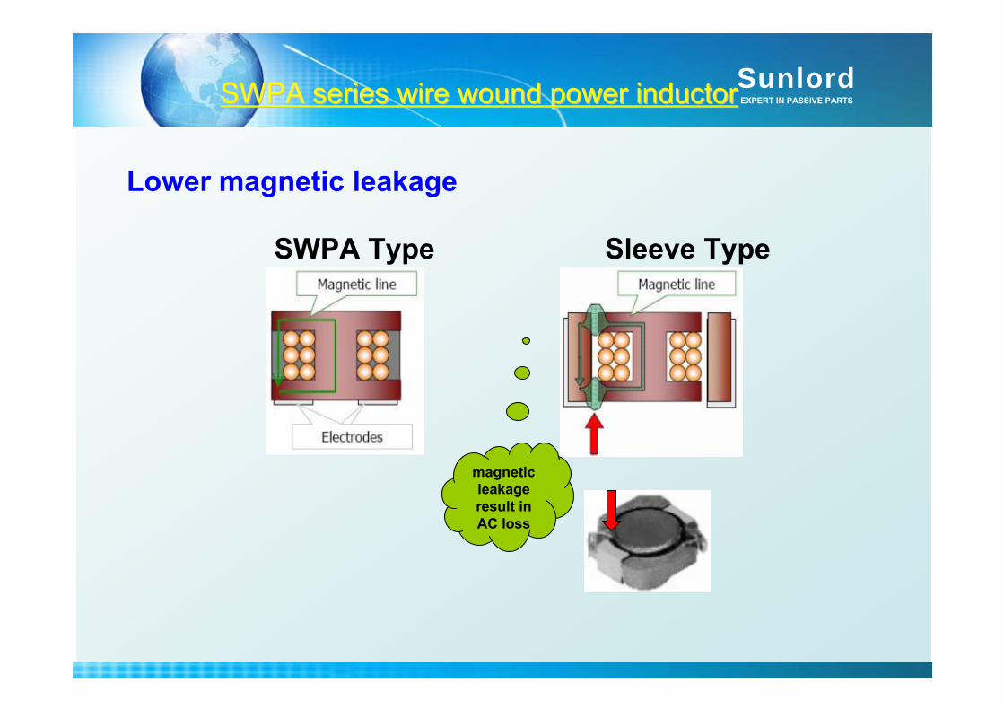
SWPA Type Sleeve Type
magnetic leakage result in AC loss
Lower magnetic leakage
SWPA series wire wound power inductor SWPA series wire wound power inductor
SunlordEXPERT IN PASSIVE PARTS
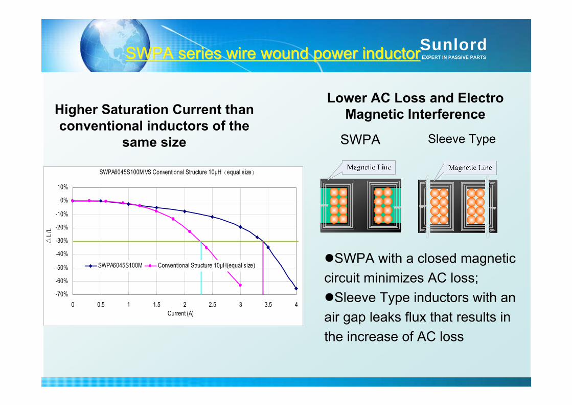
Higher Saturation Current than conventional inductors of the
same size
Lower AC Loss and Electro Magnetic Interference
SWPA with a closed magnetic circuit minimizes AC loss;
Sleeve Type inductors with an air gap leaks flux that results in the increase of AC loss
Sleeve TypeSWPA
SWPA6045S100M VS Conventional Structure 10μH(equal size)
-70%
-60%
-50%
-40%
-30%
-20%
-10%
0%
10%
0 0.5 1 1.5 2 2.5 3 3.5 4Current (A)
L/
L
SWPA6045S100M Conventional Structure 10μH(equal size)
SWPA series wire wound power inductor SWPA series wire wound power inductor
SunlordEXPERT IN PASSIVE PARTS
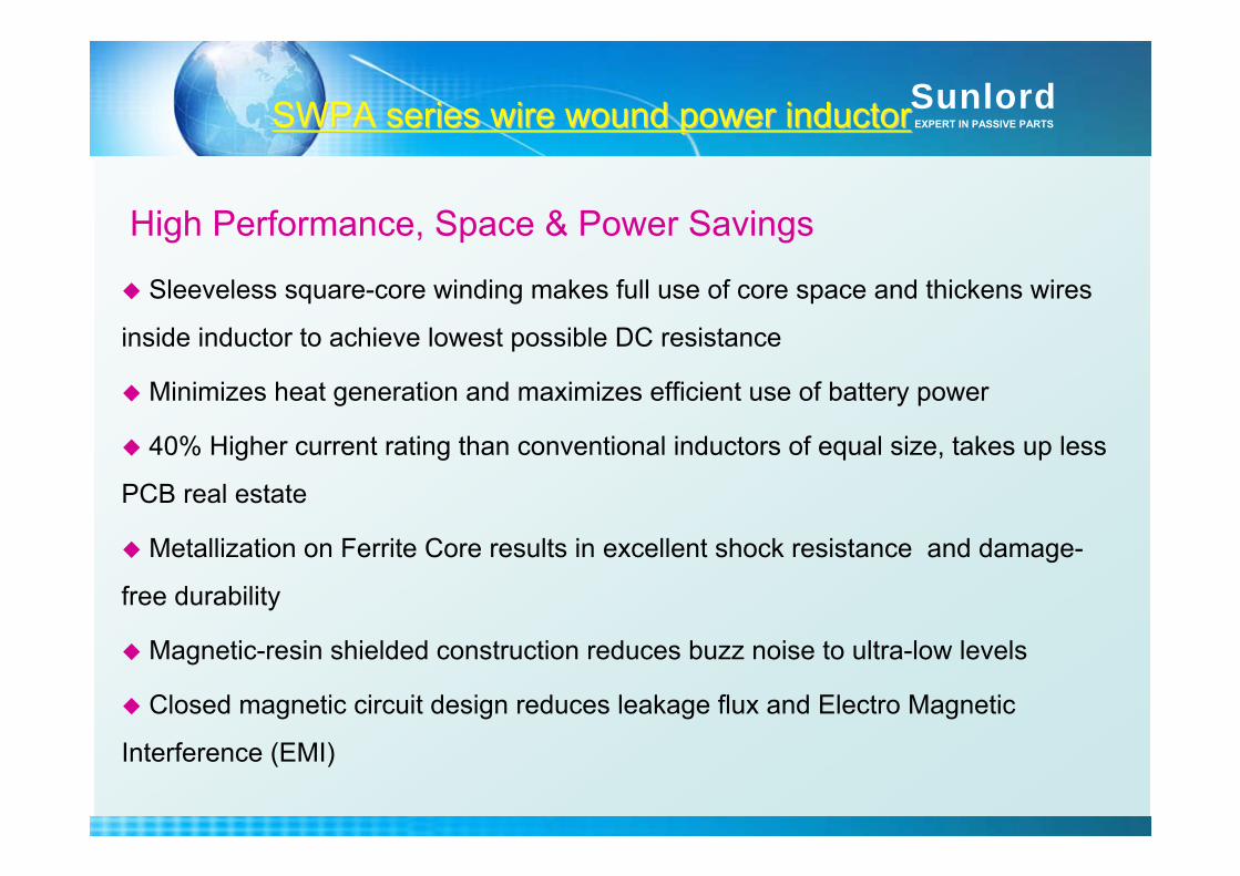
Sleeveless square-core winding makes full use of core space and thickens wires
inside inductor to achieve lowest possible DC resistance
Minimizes heat generation and maximizes efficient use of battery power
40% Higher current rating than conventional inductors of equal size, takes up less
PCB real estate
Metallization on Ferrite Core results in excellent shock resistance and damage-
free durability
Magnetic-resin shielded construction reduces buzz noise to ultra-low levels
Closed magnetic circuit design reduces leakage flux and Electro Magnetic
Interference (EMI)
SWPA series wire wound power inductor SWPA series wire wound power inductor
High Performance, Space & Power Savings
SunlordEXPERT IN PASSIVE PARTS
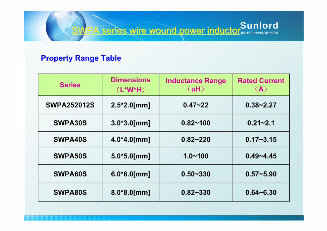
Property Range Table
SWPA series wire wound power inductor SWPA series wire wound power inductor
0.64~6.300.82~3308.0*8.0[mm]SWPA80S
0.57~5.900.50~3306.0*6.0[mm]SWPA60S
0.49~4.451.0~1005.0*5.0[mm]SWPA50S
0.17~3.150.82~2204.0*4.0[mm]SWPA40S
0.21~2.10.82~1003.0*3.0[mm]SWPA30S
0.38~2.270.47~222.5*2.0[mm]SWPA252012S
Rated Current(A)
Inductance Range(uH)
Dimensions(L*W*H)
Series
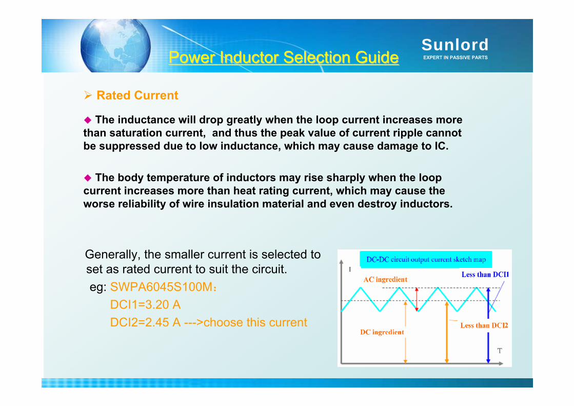
SunlordEXPERT IN PASSIVE PARTSPower Inductor Selection GuidePower Inductor Selection Guide
Generally, the smaller current is selected to set as rated current to suit the circuit.eg: SWPA6045S100M:
DCI1=3.20 ADCI2=2.45 A --->choose this current
Rated Current
The inductance will drop greatly when the loop current increases more than saturation current, and thus the peak value of current ripple cannot be suppressed due to low inductance, which may cause damage to IC.
The body temperature of inductors may rise sharply when the loop current increases more than heat rating current, which may cause the worse reliability of wire insulation material and even destroy inductors.
SunlordEXPERT IN PASSIVE PARTS
1.1. Requirement of components in LED driver circuitRequirement of components in LED driver circuit
2.2. EMC and circuit protection solution for LED driver EMC and circuit protection solution for LED driver circuitcircuit
3.3. SunlordSunlord related product presentationrelated product presentationChip Chip VaristorVaristorChip NTC Chip NTC ThermistorThermistorChip Ferrite BeadChip Power InductorChip Power InductorChip Solid Tantalum CapacitorChip Solid Tantalum Capacitor
ContentContent
SunlordEXPERT IN PASSIVE PARTS
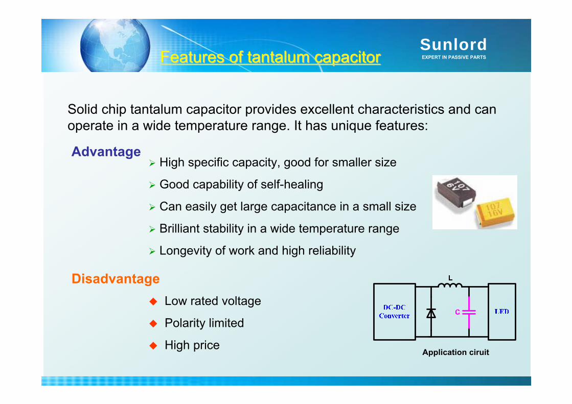
Application ciruit
High specific capacity, good for smaller size
Good capability of self-healing
Can easily get large capacitance in a small size
Brilliant stability in a wide temperature range
Longevity of work and high reliability
Low rated voltage
Polarity limited
High price
Advantage
Disadvantage
Solid chip tantalum capacitor provides excellent characteristics and can operate in a wide temperature range. It has unique features:
Features of tantalum capacitorFeatures of tantalum capacitor

SunlordEXPERT IN PASSIVE PARTS
2.5V~50V
<7.5V
16V~630V
2.5V~3150V
Rated voltage
-55~ +125
-40~ +70
-55~ +125
-55~ +85
Operating Temp.
1106 [0402]~7343 [2812]
Φ4.8*1.4~ Φ35*60
3.3*1.6*1.1~41.5*42.5*28
0402 [01005]~5750 [2220]
size
< ± 10%0.22uF~2200uF
Ta Cp.
>±30%0.1F~1000FSuper Cp.
> ± 10%680pF
~220uFFilm Cp.
> ± 10%0.10pF~47uF
MLCC
Tem. FeatureCapacitanceTypes
In general, Ta capacitor present a good performance in capacitance, operating temperature, brilliant reliability. Therefore, Ta Capacitor is fairly suitable as output capacitor in DC-DC converter circuit.
Features of tantalum capacitorFeatures of tantalum capacitor
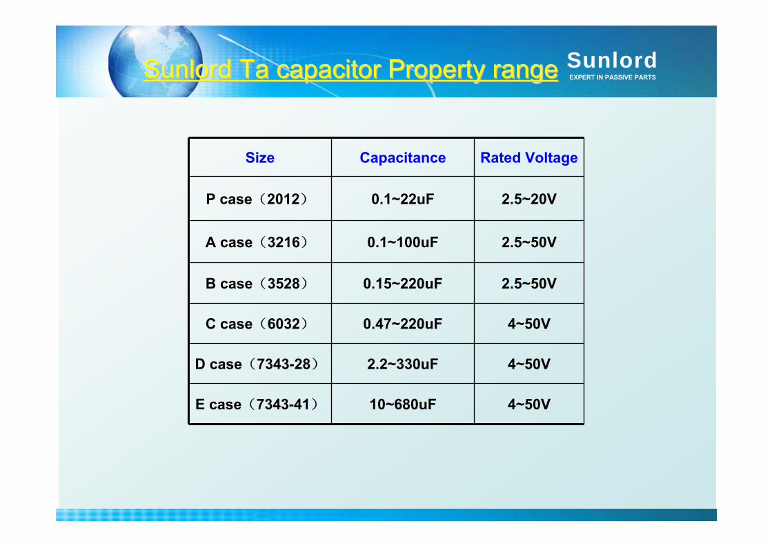
SunlordEXPERT IN PASSIVE PARTSSunlordSunlord Ta capacitor Property rangeTa capacitor Property range
2.5~50V0.15~220uFB case(3528)
4~50V0.47~220uFC case(6032)
4~50V2.2~330uFD case(7343-28)
4~50V10~680uFE case(7343-41)
2.5~50V
2.5~20V
Rated Voltage
A case(3216)
P case(2012)
Size
0.1~100uF
0.1~22uF
Capacitance
SunlordEXPERT IN PASSIVE PARTSTa Capacitor Selection GuideTa Capacitor Selection Guide
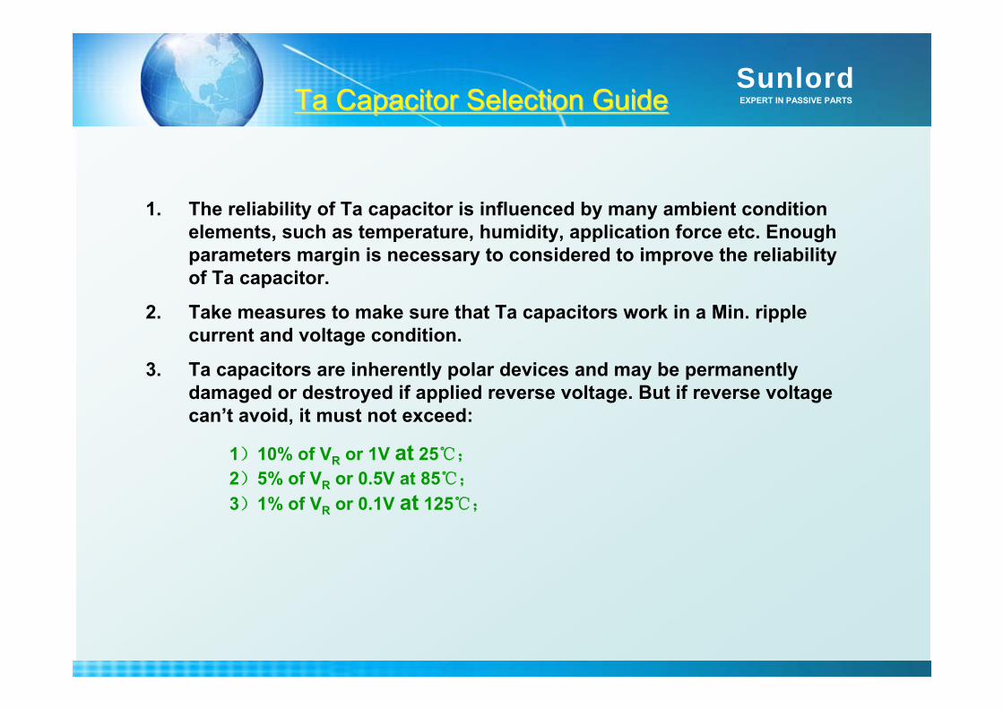
1. The reliability of Ta capacitor is influenced by many ambient condition elements, such as temperature, humidity, application force etc. Enough parameters margin is necessary to considered to improve the reliability of Ta capacitor.
2. Take measures to make sure that Ta capacitors work in a Min. ripple current and voltage condition.
3. Ta capacitors are inherently polar devices and may be permanently damaged or destroyed if applied reverse voltage. But if reverse voltage can’t avoid, it must not exceed:
1)10% of VR or 1V at 25;
2)5% of VR or 0.5V at 85;
3)1% of VR or 0.1V at 125;

SunlordEXPERT IN PASSIVE PARTSTa Capacitor Selection GuideTa Capacitor Selection Guide
4. In order to achieve high reliability, working voltage should obey:1) For general use, working voltage should derate to 70% of VR or below. For power lines or some low-impedance circuit, working voltage should derate to 30% of VR or below. 2) When operating temperature is above 85 and below 125 , voltage derating is necessary:
Vmax=
T:operating temperature; VR: rated voltage at 85
5. When Ta capacitor is used in circuit where surge current may occurred, a resistor is needed to connect in series with capacitor to prevent from damaging.
6. Margin designing is necessary to improve the reliability of Ta capacitor especially in some circuit that easily lead to short-circuit.

SunlordEXPERT IN PASSIVE PARTS