embedded systems analog electronics - umass amherstgrupen/503/slides/analogelectronics.pdf ·...
TRANSCRIPT

Laboratory for Perceptual Robotics – Department of Computer Science
Embedded Systems Analog Electronics
Laboratory for Perceptual Robotics – Department of Computer Science
Units physical units = length [meter], mass [kilogram], time [second] force - [Newton]: kg m/s2 (F=ma) torque - [N m] energy - [joule]: 1N acting through distance of 1m - [calorie]: raise the temperature of 1 gram of water by 1 degree centigrade power - [Watts]: energy rate of 1 joule/sec charge - [coulomb]: -1(charge of 0.624142 x 10¹⁹) electrons current - [Amperes]: 1 coulomb/sec voltage - [Volts]: 1 joule of energy is required to push 1 coulomb up a 1 volt potential difference

Laboratory for Perceptual Robotics – Department of Computer Science
Terminology conductor - materials (metals) with a crystalline structure with
loosely bound electrons in the (outer) valence shell donate electrons to the lattice easily
insulators - materials with tightly bound electrons in the valence shell
semiconductors - a material whose conductivity can be
controlled
Laboratory for Perceptual Robotics – Department of Computer Science
Circuit Analysis Tools Kirchoff’s Current Law - the sum of the current! flowing into a junction is zero (conservation of! electrical charge)!
Kirchoff’s Voltage Law - the sum of the voltages!around any closed circuit is zero!
I1 + I2 + I3 + I4 = 0!
ΔV1+ ΔV2 + ΔV3 + ΔV4 + ΔV5 = 0!

Laboratory for Perceptual Robotics – Department of Computer Science
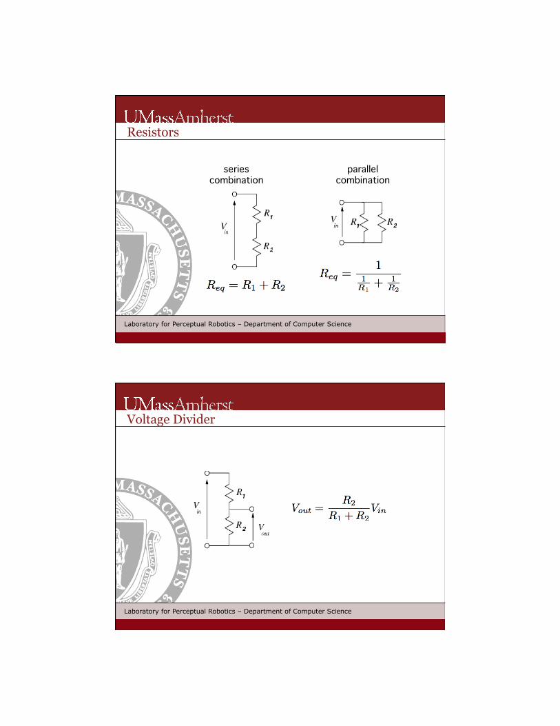
Resistors
resistance - [Ohms, Ω]: a resistance of 1 Ω permits a 1 A current flow given 1 V of electromotive potential
power dissipated in resistors - P=VI=V2/R=I2R
Laboratory for Perceptual Robotics – Department of Computer Science
Resistors color digit multiplier tolerance!black ! 0 100!
brown ! 1 101 ! 1%!red ! 2 102 ! 2%!orange 3 103!
yellow ! 4 104!
green ! 5 105 0.50%!blue ! 6 106 0.25%!violet ! 7 107 0.10%!grey ! 8 108 0.05%!white ! 9 109!
gold ! 10-1 5%!silver ! 10-2 10%!none ! ! ! 20%!
power specs: 1/8, 1/4, 1/2, 1, 10 W![d1 d2 exp precision]: !
for example: 4700 W at 5%!yellow violet red gold!
Laboratory for Perceptual Robotics – Department of Computer Science
Resistors
series !combination!
parallel !combination!
Laboratory for Perceptual Robotics – Department of Computer Science
Voltage Divider

Laboratory for Perceptual Robotics – Department of Computer Science
Capacitors • capacitance - [Farads]: Michael Faraday !• capacitor - two terminal device that stores!
energy in the form of an electric charge!
• two conductors separated by a thin layer of dielectric • capacitance ~ conductor surface area, thinness of dielectric • two adjacent wires in a ribbon cable are subject to capacitive crosstalk
(ground every other wire) • big capacitors are polarized, terrible accuracy, temperature stability,
leakage, and lifetime---a loud buzzing noise from electronics could be an electrolytic capacitor has died!
Laboratory for Perceptual Robotics – Department of Computer Science
Capacitors
series !combination! parallel !
combination!

Laboratory for Perceptual Robotics – Department of Computer Science
RC Circuits
Laboratory for Perceptual Robotics – Department of Computer Science
RC Circuits
timing - RC is called the time constant, τ, of the circuit, voltage will fall to 37% of its initial value in RC seconds.!!smoothing - high frequency noise on top of a slowly varying signal can be rejected by observing the signal through a relatively large RC time constant!
Laboratory for Perceptual Robotics – Department of Computer Science
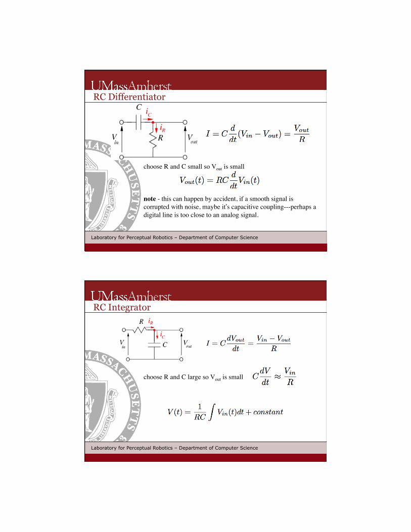
RC Differentiator
choose R and C small so Vout is small note - this can happen by accident, if a smooth signal is corrupted with noise, maybe it’s capacitive coupling---perhaps a digital line is too close to an analog signal.!
Laboratory for Perceptual Robotics – Department of Computer Science
RC Integrator
choose R and C large so Vout is small !

Laboratory for Perceptual Robotics – Department of Computer Science
Inductors
• inductance - [Henries]: 1 volt across 1 Henry produces a current that increases at 1 amp per second!
• an inductor is normally formed from a coil of wire that may be wound on a core of magnetic material.
• a voltage source across an inductor causes the current to rise as a ramp. • stopping a current going through an inductor generates a high voltage. !
Laboratory for Perceptual Robotics – Department of Computer Science
Inductors
series !combination! parallel !
combination!
no mutual inductance!

Laboratory for Perceptual Robotics – Department of Computer Science
Transformers
• transformers are the main reason why AC power is used. • often first stage for low voltage DC power
“gearbox” !for AC voltage and current!primary! secondary!
I ~ ω!V ~ τ!constant power: VI (τω)!
6 : 3 η=6/3!
Vin! Vout!step-down:!
less voltage!more current!
Vout!Vin!
3 : 6 η=3/6!
step-up:!more voltage!less current!
Laboratory for Perceptual Robotics – Department of Computer Science
Switches
Switches are classified in terms of the number of poles and number of throws. Common types are SPST DPDT SPDT, sometimes with center-off position. Note that contacts bounce for about a millisecond after closing. This is noticeable to logic circuits, which can respond in nanoseconds.
SPST!SPDT!
DPDT!

Laboratory for Perceptual Robotics – Department of Computer Science
Relays
• electro-magnetically operated switches • input behaves as an inductor with some loss (the energy required to operate
the switch as well as the normal resistance) • the output circuit behaves as a switch • take milliseconds to operate • can only manage a few million operations • can take a lot of abuse, unlike electronic switches which can die from a very
brief overvoltage.
Laboratory for Perceptual Robotics – Department of Computer Science
TuteBot a circuit, a chassis, a sensor, a battery, and two motors…!
programmed by adjusting two potentiometers!

Laboratory for Perceptual Robotics – Department of Computer Science
TuteBot
• diode D alleviates!excessive voltage on collector when the field in the inductor collapses!
• capacitor C2 smoothes!voltage spikes from the motor!
• with Vout(0) = 6V!!
22 Laboratory for Perceptual Robotics – Department of Computer Science
Implementation suggestions
Soldering!Male/female headers!Wheels!Motors (mounting, galvanized wire, sheet Al)!DIP sockets - potentiometers, DPDT switches!SIP sockets - CdS photoresitors!

23 Laboratory for Perceptual Robotics – Department of Computer Science
Soldering
solder - a layer of lead-tin alloy with a relatively low melting point around a core of flux that cleans the junction with which to fix two conductors together in an intimate (low resistance) junction.!!No - stainless steel, aluminum - they have an oxide coating!Yes - solid copper, “tinned” copper, brass, iron, most steels!!
heat up both surfaces to be joined to the melting point of the solder, feed a small amount of fresh solder from the reel into the joint!
!heat the joint with a soldering iron---set the temperature on your soldering station to 320 degrees Celcius---molten solder is hot enough to burn you.!!solder wets the metal being joined---check the shape of the solder meniscus. If the solder forms a small spherical blob on the metal, the joint is a bad "dry" joint. If the surface of the solder is “sucked in” to the joint (concave), then you probably have a good joint.!
24 Laboratory for Perceptual Robotics – Department of Computer Science
Tips on Soldering Metal surfaces must be clean. Remove dull (oxide) surfaces from copper (make the surface bright). Components (transistors, resistors) have thermal stress limits---beware overheating---if in doubt, use the little heat-sinks (aluminum clamps) on the leads of a component to protect it by adding thermal mass during soldering. Typically only a few seconds of heat need to be applied to small joints.!!!Solid wire - easy to work with, but solid wires that flex will eventually fail by metal fatigue, giving rise to malfunctions that are hard/impossible to locate.!!Thin gauge stranded wire - survives flexion much better. Twist and “tin” the end of the wire. Two such wires soldered together form a rigid joint. If possible, “strain relieve” the joint so that flexure is confined to the part of the wire that is still stranded. A short length of heat shrink tubing over the end of the wire is usually enough to reinforce (and protect/insulate) the rigid joint.!!

25 Laboratory for Perceptual Robotics – Department of Computer Science
Debugging
Check your work as you go!!! Bad joints mean intermittent circuit problems that are hard to find. Connect what you intended to connect and nothing else. Configure your multimeter to the continuity/diode check mode and check every joint as you make it. When you’re done, do a basic check before you apply power to a circuit or all your hard work may go poof. Watch out for excessive current consumption by the circuit---usually indicative of a short.!!Desoldering - A bad solder joint can be repaired by heating it up and using a solder suction device. Take care to avoid thermal stress limits when desoldering.!!It's difficult to desolder multiple pin IC packages. Always put integrated circuits in sockets when making an experimental board. Sockets isolate ICs from thermal stresses and also make it easier to debug a board because you can check voltages before you install the chip or you can replace it if necessary.!
26 Laboratory for Perceptual Robotics – Department of Computer Science
Sockets and Connectors
Connectors are the bane of electronics---they are generally more costly to make and cause errors at a higher rate than other components of a circuit. Connectors should be unambiguous so that power and signal can not be mis-applied. !!Our general purpose (perforated) boards are drilled with holes on 0.1" centers. Typically, we use male and female headers to connect to boards. Put female headers on the board, use male headers as plugs that fit into them. The Handyboard user’s manual illustrates a very nice way of cabling using ribbon cables soldered to male headers, insulated and strain relieved using shrink tube, and polarized to fit into the female header.!
sensor signal!
+5V supply!ground!