embedded software for functional safety
TRANSCRIPT
V2.02.00 | 2017-06-19
MICROSAR Safe
Embedded Software for Functional Safety

Functional Safety
Introduction
ISO 26262
has been published in 2011 addressing safety-related electronic automotive systems
To reduce liability risks state of the art development methods as described in the ISO 26262 should be applied for such systems.
2/49
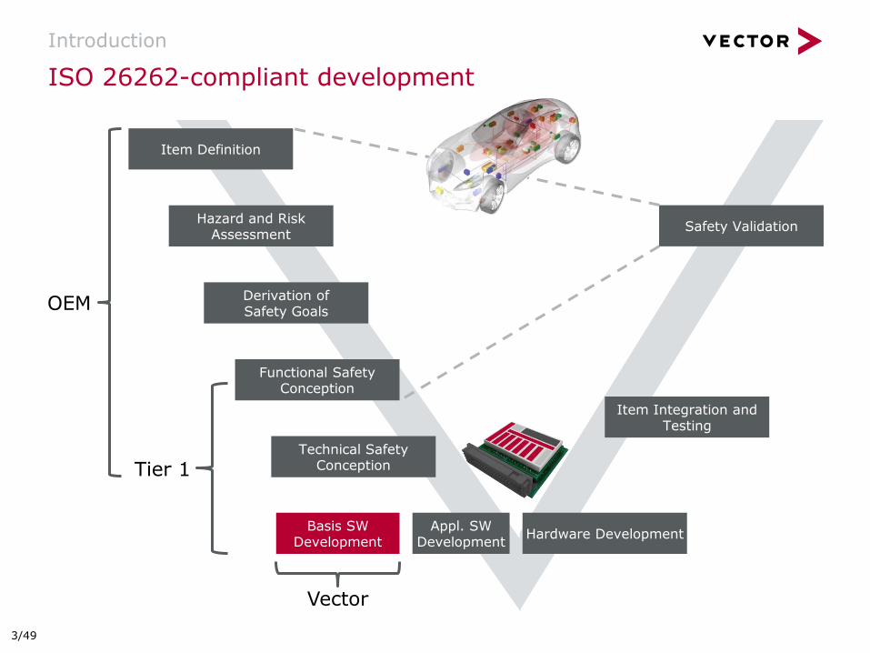
ISO 26262-compliant development
Introduction
Item Integration and Testing
Safety Validation
Item Definition
Hazard and Risk Assessment
Derivation of Safety Goals
Functional Safety Conception
Technical Safety Conception
Basis SW Development
Hardware Development
Tier 1
Vector
OEM
Appl. SW Development
3/49
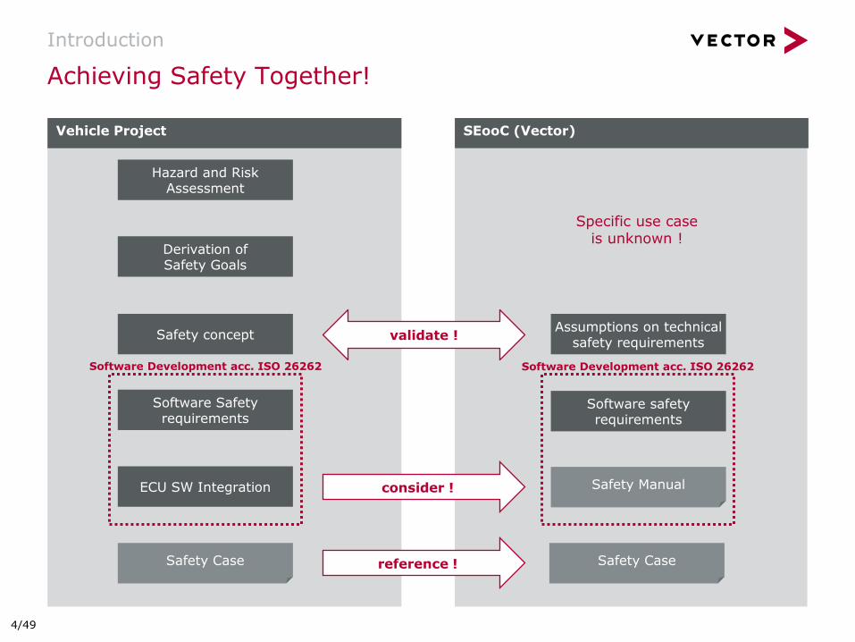
SEooC (Vector)
Vehicle Project
Achieving Safety Together!
Introduction
Software safety requirements
ECU SW Integration
Safety concept
Safety Manual
Safety Case
consider !
validate !
reference ! Safety Case
Software Safety requirements
Assumptions on technical safety requirements
Specific use case is unknown !
Hazard and Risk Assessment
Derivation of Safety Goals
Software Development acc. ISO 26262 Software Development acc. ISO 26262
4/49
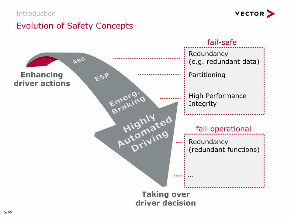
Evolution of Safety Concepts
Introduction
Redundancy (e.g. redundant data)
Partitioning
High Performance Integrity
Redundancy (redundant functions)
Enhancing driver actions
Taking over driver decision
fail-safe
…
fail-operational
5/49
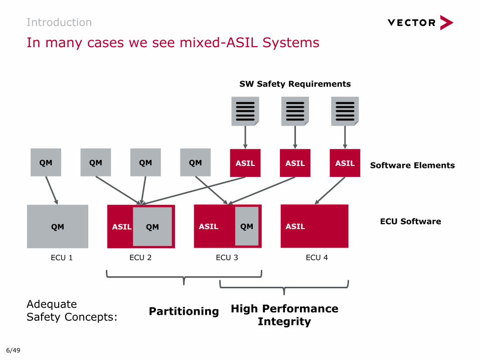
In many cases we see mixed-ASIL Systems
Introduction
SW Safety Requirements
Software Elements
ECU Software
QM QM QM QM
ASIL ASIL QM
ECU 1 ECU 2
ASIL QM QM
ASIL ASIL
ECU 3 ECU 4
ASIL
High Performance Integrity
Partitioning Adequate Safety Concepts:
6/49

Safety Concepts and Contribution of MICROSAR Safe
Introduction
SafeRTE
SWC SWC
SafeOS
SWC
Hardware
SWC
BSW
MCAL
ASIL QM
Safe
WD
G
E2E
Partitioning High Performance Integrity
SafeRTE
SWC
SafeOS
MCAL
SafeBSW
ASIL QM
SWC
Hardware
SWC SWC
Safe
WD
G
E2E
SafeOS
SafeWDG
SafeE2E
SafeRTE
ISO 26262 requires that software with different ASIL in the same element do not interfere with respect to memory, timing and communication aspects
MSR Safe Components Rationale
SafeOS
SafeWDG
SafeE2E
SafeRTE
SafeBSW
ISO 26262 requires to implement software components of different ASIL, or safety-related and non-safety-related software components, in accordance with the highest ASIL
MSR Safe Components Rationale
7/49

Safety Building Blocks of MICROSAR Safe
Introduction
Supports memory partitioning using an MPU
Provides safe context switch for each safety related task:
register settings
stack pointer and program counter
MPU settings
Available for single- and multi-core
OS Applications can be restarted individually
Detects timing and execution order faults
Provides deadline, alive and logic monitoring
Capable of using internal or external watchdogs as well as system basis chips (SBCs)
Ensures safe communication between ECUs
Available as E2E Protection Wrapper and E2E Transformer
All AUTOSAR profiles supported
MICROSAR SafeOS MICROSAR SafeWDG
MICROSAR SafeE2E
Ensures safe communication within the ECU
Supports safe communication across partition boundaries to exchange information between ASIL and QM applications
MICROSAR SafeRTE
Increased performance
complete BSW as ASIL software
reduced partition switches
Additional safety requirements, e.g.:
Correct initialization using an ASIL EcuM
Safe write/read of non-volatile data
MICROSAR SafeBSW
8/49

Introduction
MICROSAR SafeOS
MICROSAR SafeWDG
MICROSAR SafeE2E
MICROSAR SafeRTE
MICROSAR SafeBSW
Process and Services
Summary
Agenda
9/49
MICROSAR SafeOS
MICROSAR SafeOS
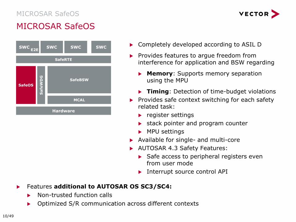
Completely developed according to ASIL D
Provides features to argue freedom from interference for application and BSW regarding
Memory: Supports memory separation using the MPU
Timing: Detection of time-budget violations
Provides safe context switching for each safety related task:
register settings
stack pointer and program counter
MPU settings
Available for single- and multi-core
AUTOSAR 4.3 Safety Features:
Safe access to peripheral registers even from user mode
Interrupt source control API
Features additional to AUTOSAR OS SC3/SC4:
Non-trusted function calls
Optimized S/R communication across different contexts
SafeRTE
SWC
SafeOS
MCAL
SafeBSW
SWC
Hardware
SWC SWC
Safe
WD
G
E2E
10/49
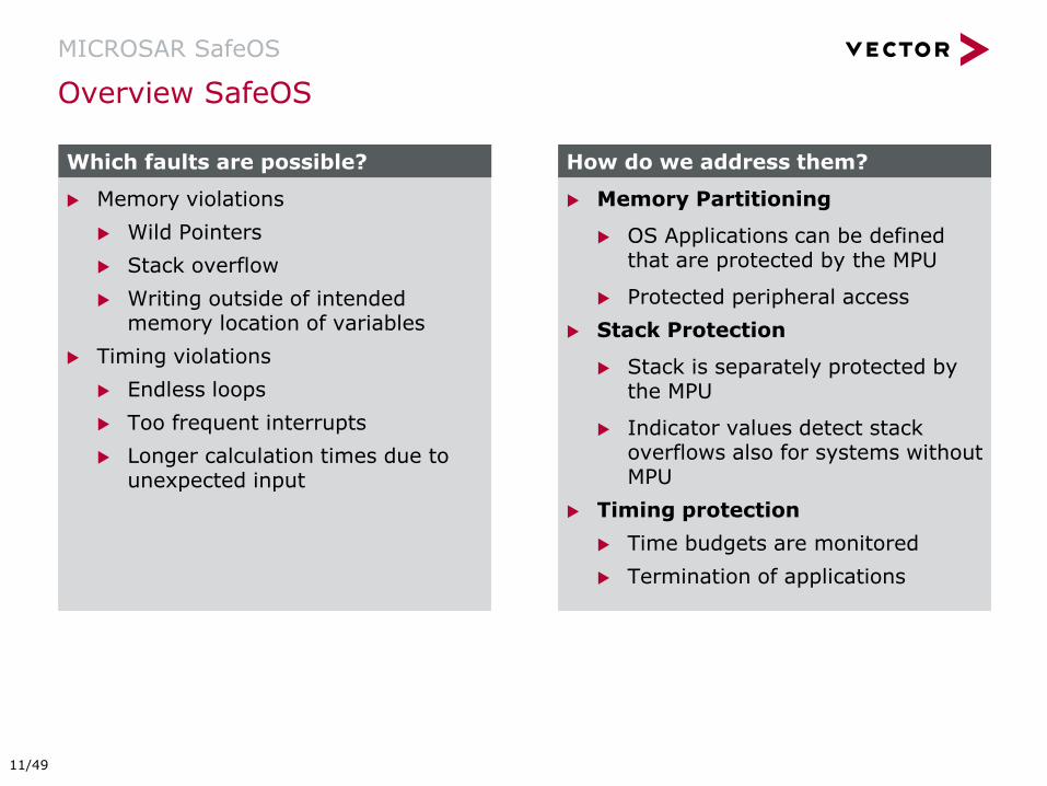
Overview SafeOS
MICROSAR SafeOS
Memory Partitioning
OS Applications can be defined that are protected by the MPU
Protected peripheral access
Stack Protection
Stack is separately protected by the MPU
Indicator values detect stack overflows also for systems without MPU
Timing protection
Time budgets are monitored
Termination of applications
Memory violations
Wild Pointers
Stack overflow
Writing outside of intended memory location of variables
Timing violations
Endless loops
Too frequent interrupts
Longer calculation times due to unexpected input
Which faults are possible? How do we address them?
11/49
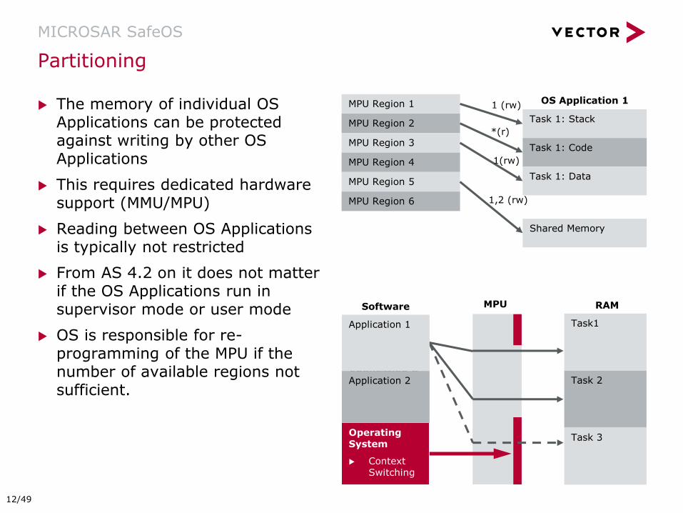
The memory of individual OS Applications can be protected against writing by other OS Applications
This requires dedicated hardware support (MMU/MPU)
Reading between OS Applications is typically not restricted
From AS 4.2 on it does not matter if the OS Applications run in supervisor mode or user mode
OS is responsible for re-programming of the MPU if the number of available regions not sufficient.
Partitioning
MICROSAR SafeOS
MPU Region 1
MPU Region 2
MPU Region 3
MPU Region 4
MPU Region 5
MPU Region 6
Task 1: Stack
Task 1: Code
Task 1: Data
OS Application 1
Shared Memory
1 (rw)
*(r)
1(rw)
1,2 (rw)
Software
Application A
Application B
Operating System
Context Switching
MPU RAM
Application 1
Application 2
Task1
Task 2
Task 3
12/49
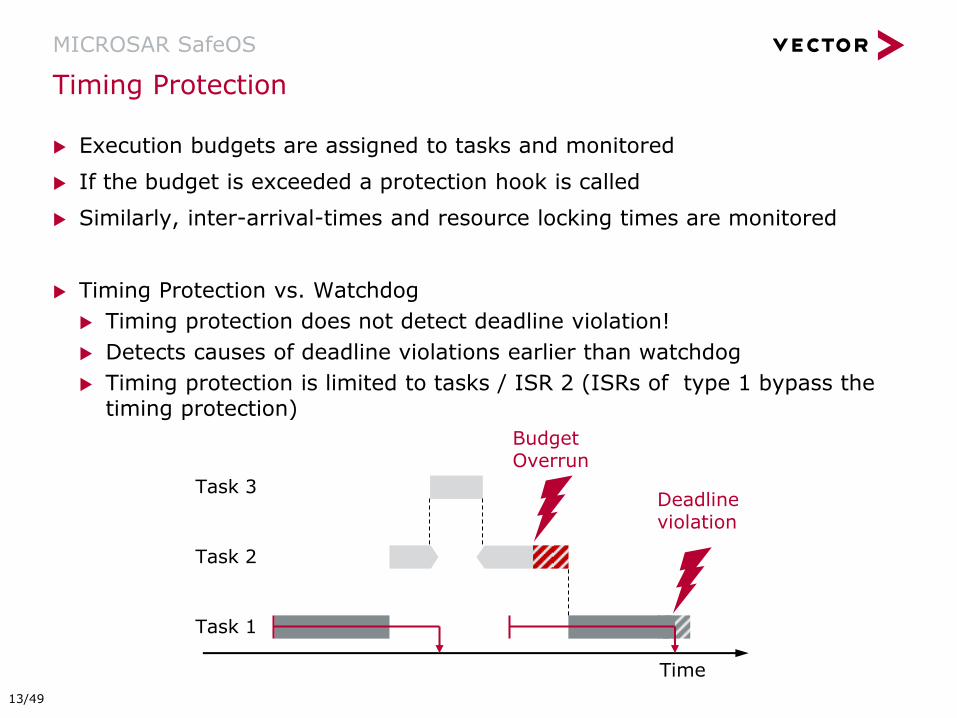
Execution budgets are assigned to tasks and monitored
If the budget is exceeded a protection hook is called
Similarly, inter-arrival-times and resource locking times are monitored
Timing Protection vs. Watchdog
Timing protection does not detect deadline violation!
Detects causes of deadline violations earlier than watchdog
Timing protection is limited to tasks / ISR 2 (ISRs of type 1 bypass the timing protection)
Timing Protection
MICROSAR SafeOS
Time
Task 1
Task 3
Task 2
Budget Overrun
Deadline violation
13/49
Introduction
MICROSAR SafeOS
MICROSAR SafeWDG
MICROSAR SafeE2E
MICROSAR SafeRTE
MICROSAR SafeBSW
Process and Services
Summary
Agenda
14/49

BSW
A watchdog can detect timing violations in the Application and BSW
Also provides Program Flow Monitoring up to ASIL D
Is supervised by independent HW-Watchdog
On detected violations in a supervised entity the ECU can be reset
Acknowledgements of a checkpoint are performed without context switch
Overview Watchdog
MICROSAR SafeWDG
SWC
MICROSAR RTE
Safe
Co
mp
lex D
riv
ers
Microcontroller
BSW
MCAL
SWC SWC
WdgDrv
WdgM
Checkpoint Checkpoint
Ch
eckp
oin
t
WdgIf
Watchdog
QM Software ASIL Software
15/49
Overview SafeWDG
MICROSAR SafeWDG
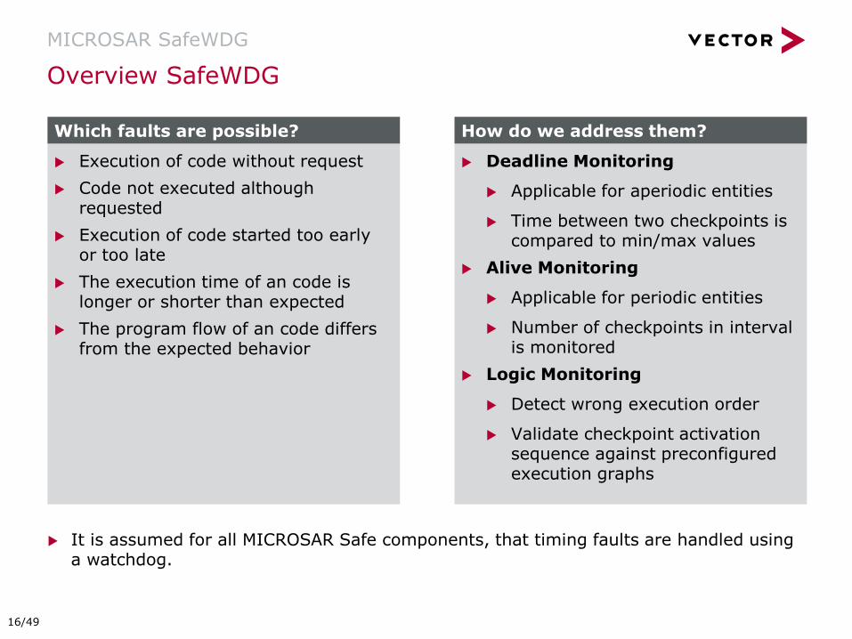
Deadline Monitoring
Applicable for aperiodic entities
Time between two checkpoints is compared to min/max values
Alive Monitoring
Applicable for periodic entities
Number of checkpoints in interval is monitored
Logic Monitoring
Detect wrong execution order
Validate checkpoint activation sequence against preconfigured execution graphs
Execution of code without request
Code not executed although requested
Execution of code started too early or too late
The execution time of an code is longer or shorter than expected
The program flow of an code differs from the expected behavior
Which faults are possible? How do we address them?
It is assumed for all MICROSAR Safe components, that timing faults are handled using a watchdog.
16/49

Watchdog Manager combines all Supervised Entity states to a system state
Depending on the system state the Watchdog Manager triggers the Watchdog Driver
Global Watchdog State
MICROSAR SafeWDG
WdgM
Wdg
OK/NOK
SE1 SE2 SE3 SE4
trigger
17/49
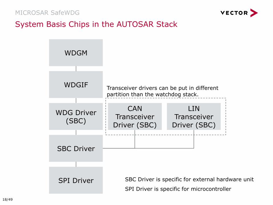
System Basis Chips in the AUTOSAR Stack
MICROSAR SafeWDG
WDGM
WDGIF
WDG Driver (SBC)
SBC Driver
SPI Driver
CAN Transceiver
Driver (SBC)
LIN Transceiver
Driver (SBC)
Transceiver drivers can be put in different partition than the watchdog stack.
SBC Driver is specific for external hardware unit
SPI Driver is specific for microcontroller
18/49
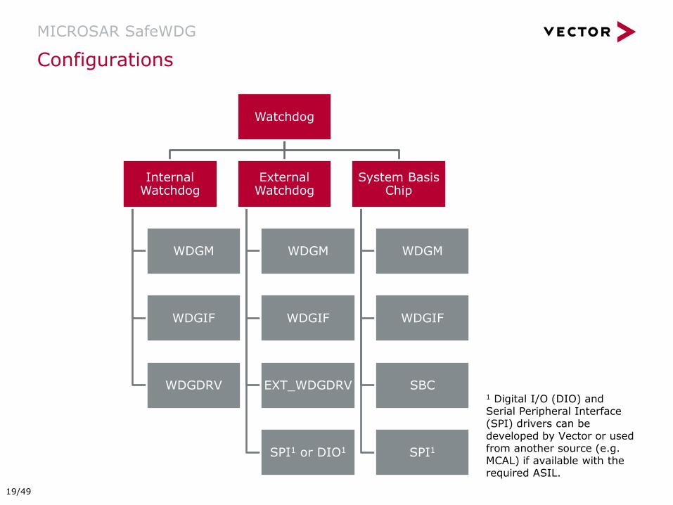
Configurations
MICROSAR SafeWDG
Watchdog
Internal Watchdog
WDGM
WDGIF
WDGDRV
External Watchdog
WDGM
WDGIF
EXT_WDGDRV
SPI1 or DIO1
System Basis Chip
WDGM
WDGIF
SBC
SPI1
1 Digital I/O (DIO) and Serial Peripheral Interface (SPI) drivers can be developed by Vector or used from another source (e.g. MCAL) if available with the required ASIL.
19/49

Introduction
MICROSAR SafeOS
MICROSAR SafeWDG
MICROSAR SafeE2E
MICROSAR SafeRTE
MICROSAR SafeBSW
Process and Services
Summary
Agenda
20/49

Communication from one SWC to another SWC on a different ECU over an unsafe channel
This channel comprises:
RTE
Com-Stack
Bus Controller
Cabling
E2E Overview
MICROSAR SafeE2E
HW
BSW
SWC
HW
BSW
SWC
E2E is able to detect if fault occurred during the transmission
The application needs to use this information to react on the faults
SafeRTE
SWC
SafeOS
MCAL
SafeBSW
SWC
Hardware
SWC SWC
Safe
WD
G
E2E
21/49
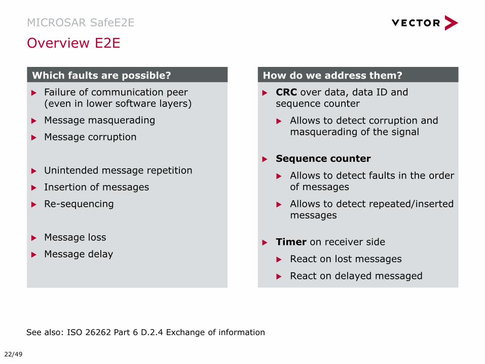
Overview E2E
MICROSAR SafeE2E
CRC over data, data ID and sequence counter
Allows to detect corruption and masquerading of the signal
Sequence counter
Allows to detect faults in the order of messages
Allows to detect repeated/inserted messages
Timer on receiver side
React on lost messages
React on delayed messaged
Failure of communication peer (even in lower software layers)
Message masquerading
Message corruption
Unintended message repetition
Insertion of messages
Re-sequencing
Message loss
Message delay
Which faults are possible? How do we address them?
See also: ISO 26262 Part 6 D.2.4 Exchange of information
22/49
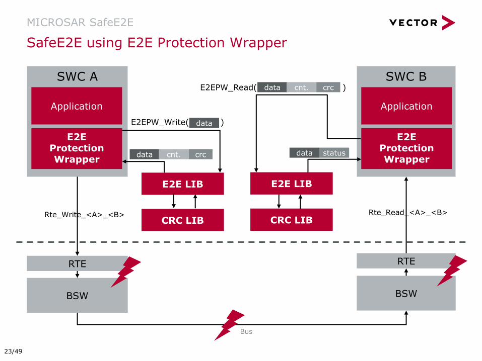
SafeE2E using E2E Protection Wrapper
MICROSAR SafeE2E
RTE RTE
BSW BSW
Bus
verify CRC
E2E LIB
Rte_Write_<A>_<B> Rte_Read_<A>_<B> CRC LIB
E2EPW_Write( )
SWC A
Application
E2E Protection Wrapper
E2E LIB
CRC LIB
SWC B
Application
E2E Protection Wrapper
data
data cnt. crc data
data cnt. crc E2EPW_Read( )
status
23/49
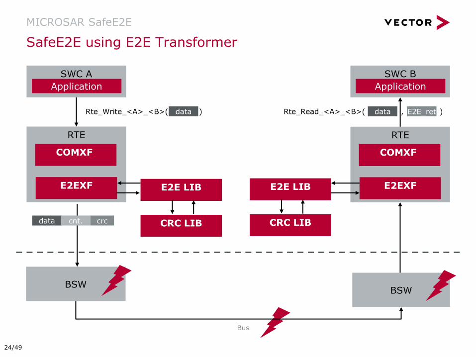
SafeE2E using E2E Transformer
MICROSAR SafeE2E
RTE
BSW BSW
Bus
E2E LIB
Rte_Write_<A>_<B>( ) Rte_Read_<A>_<B>( , )
CRC LIB
SWC A SWC B
data
data cnt. crc
COMXF
E2EXF
RTE
COMXF
E2EXF
E2E LIB
CRC LIB
E2E_ret data
Application Application
24/49
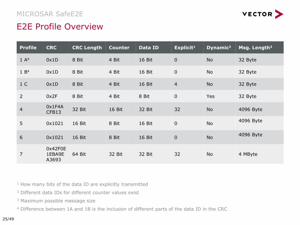
Other OEM specific E2E Profiles are available on request.
E2E Profile Overview
MICROSAR SafeE2E
Profile CRC CRC Length Counter Data ID Explicit1 Dynamic2 Msg. Length3
1 A4 0x1D 8 Bit 4 Bit 16 Bit 0 No 32 Byte
1 B4 0x1D 8 Bit 4 Bit 16 Bit 0 No 32 Byte
1 C 0x1D 8 Bit 4 Bit 16 Bit 4 No 32 Byte
2 0x2F 8 Bit 4 Bit 8 Bit 0 Yes 32 Byte
4 0x1F4ACFB13
32 Bit 16 Bit 32 Bit 32 No 4096 Byte
5 0x1021 16 Bit 8 Bit 16 Bit 0 No 4096 Byte
6 0x1021 16 Bit 8 Bit 16 Bit 0 No 4096 Byte
7 0x42F0E1EBA9EA3693
64 Bit 32 Bit 32 Bit 32 No 4 MByte
1 How many bits of the data ID are explicitly transmitted
2 Different data IDs for different counter values exist
3 Maximum possible message size
4 Difference between 1A and 1B is the inclusion of different parts of the data ID in the CRC
25/49

Configurations
MICROSAR SafeE2E
E2E Protection
Protection Wrapper Solution
E2ELIB
CRCLIB
Transformer Solution
COMXF and/or SOMEIPXF
E2ELIB
CRCLIB Protection Wrapper only supports Profiles 1, 2 and JLR
26/49
Introduction
MICROSAR SafeOS
MICROSAR SafeWDG
MICROSAR SafeE2E
MICROSAR SafeRTE
MICROSAR SafeBSW
Process and Services
Summary
Agenda
27/49
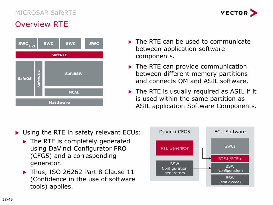
The RTE can be used to communicate between application software components.
The RTE can provide communication between different memory partitions and connects QM and ASIL software.
The RTE is usually required as ASIL if it is used within the same partition as ASIL application Software Components.
Overview RTE
MICROSAR SafeRTE
Using the RTE in safety relevant ECUs:
The RTE is completely generated using DaVinci Configurator PRO (CFG5) and a corresponding generator.
Thus, ISO 26262 Part 8 Clause 11 (Confidence in the use of software tools) applies.
DaVinci CFG5 ECU Software
RTE Generator
RTE.h/RTE.c
BSW Configuration generators
BSW (configuration)
SWCs
BSW (static code)
SafeRTE
SWC
SafeOS
MCAL
SafeBSW
SWC
Hardware
SWC SWC
Safe
WD
G
E2E
28/49

Derivation of Tool Confidence Level (TCL)
MICROSAR SafeRTE
Tool
features and
their use
cases
TI2
TI1
TD3
TD2
TD1
TCL2
TCL1
TCL3
Tool Impact Tool Error
Detection
Tool
Confidence
Level
Tool Classification Tool Qualification
ASIL
Qualification methods
for TCL3
Qualification methods
for TCL2
No qualification
required
Tool classification and qualification are usually performed by the user of the tool.
29/49

Manual qualification of CFG5 or the generated software by the user is necessary!
RTE vs. SafeRTE
MICROSAR SafeRTE
Classification of RTE:
TI2: “a malfunction of a particular software tool can introduce or fail to detect errors in a safety-related item or element being developed”
TD1: “high degree of confidence that a malfunction and its corresponding erroneous output will be prevented or detected”
Classification of RTE:
TI2: “a malfunction of a particular software tool can introduce or fail to detect errors in a safety-related item or element being developed”
TD2: “there is a medium degree of confidence that a malfunction and its corresponding erroneous output will be prevented or detected”
RTE SafeRTE
Vector provides argumentation to classify
CFG5 as TCL1.
Classification of CFG5 as TCL2 necessary
No qualification for TCL 1 tools needed!
30/49

Development at Vector
CFG5
Development at customer
RTE.h/RTE.c under test
Arguments for TD1 in Detail
MICROSAR SafeRTE
RTE Generator
RTE.h/RTE.c under test
RTE.h/RTE.c
ARG3: Output of RTE Generator is integrated and verified
according to ISO 26262:6-10/11 by customer based on
configuration feedback provided by RTE Analyzer.
ARG2: Output of RTE Generator is analyzed by RTE Analyzer.
ARG1: RTE Generator is developed with additional effort.
ARG1a: Output of RTE Generator is tested according to ISO 26262:6-9.
Use during item development by customer
Test during CFG5/RTE development
31/49
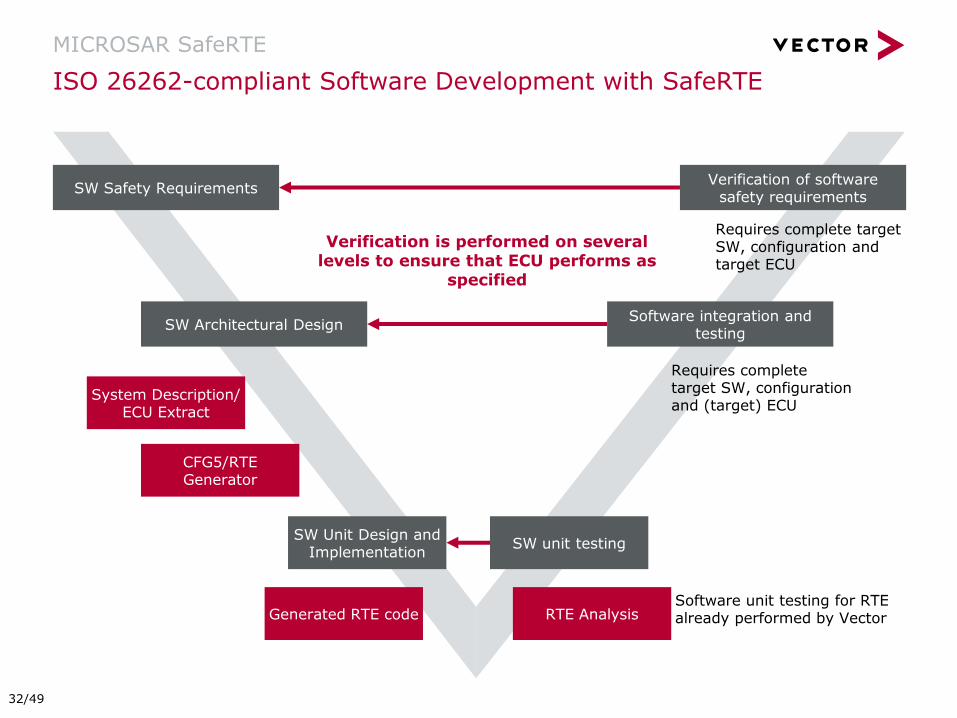
ISO 26262-compliant Software Development with SafeRTE
MICROSAR SafeRTE
Software integration and testing
Verification of software safety requirements
SW Safety Requirements
SW unit testing
SW Architectural Design
SW Unit Design and Implementation
System Description/ ECU Extract
RTE Analysis
CFG5/RTE Generator
Generated RTE code Software unit testing for RTE already performed by Vector
Verification is performed on several levels to ensure that ECU performs as
specified
Requires complete target SW, configuration and target ECU
Requires complete target SW, configuration and (target) ECU
32/49
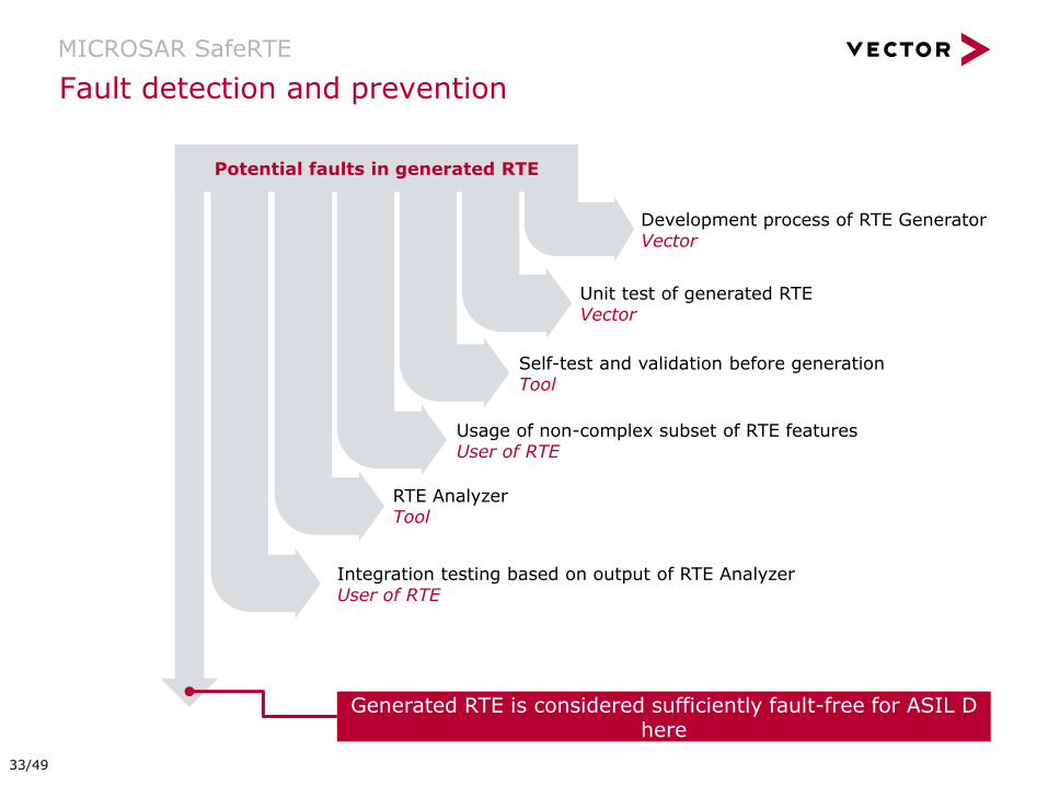
Fault detection and prevention
MICROSAR SafeRTE
Potential faults in generated RTE
Development process of RTE Generator Vector
Unit test of generated RTE Vector
Self-test and validation before generation Tool
RTE Analyzer Tool
Usage of non-complex subset of RTE features User of RTE
Integration testing based on output of RTE Analyzer User of RTE
Generated RTE is considered sufficiently fault-free for ASIL D here
33/49
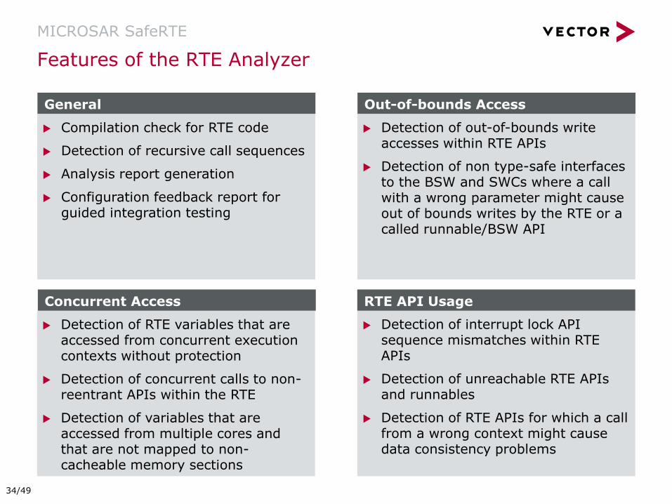
Features of the RTE Analyzer
MICROSAR SafeRTE
Compilation check for RTE code
Detection of recursive call sequences
Analysis report generation
Configuration feedback report for guided integration testing
General
Detection of RTE variables that are accessed from concurrent execution contexts without protection
Detection of concurrent calls to non-reentrant APIs within the RTE
Detection of variables that are accessed from multiple cores and that are not mapped to non-cacheable memory sections
Concurrent Access
Detection of out-of-bounds write accesses within RTE APIs
Detection of non type-safe interfaces to the BSW and SWCs where a call with a wrong parameter might cause out of bounds writes by the RTE or a called runnable/BSW API
Out-of-bounds Access
Detection of interrupt lock API sequence mismatches within RTE APIs
Detection of unreachable RTE APIs and runnables
Detection of RTE APIs for which a call from a wrong context might cause data consistency problems
RTE API Usage
34/49

RTE
MPU restricts write access from other partitions put may allow read access
Data is stored in own partition and event notifies availability of data
Principle is identical for ASIL QM communication
Example – Inter-partition Sender/Receiver Communication
MICROSAR SafeRTE
SWC 1
Rte_write()
Part
itio
n
bord
er
Data
element
read access
write access
Partition 2 Partition 1
ASIL D QM
SWC 2
Rte_read()
35/49
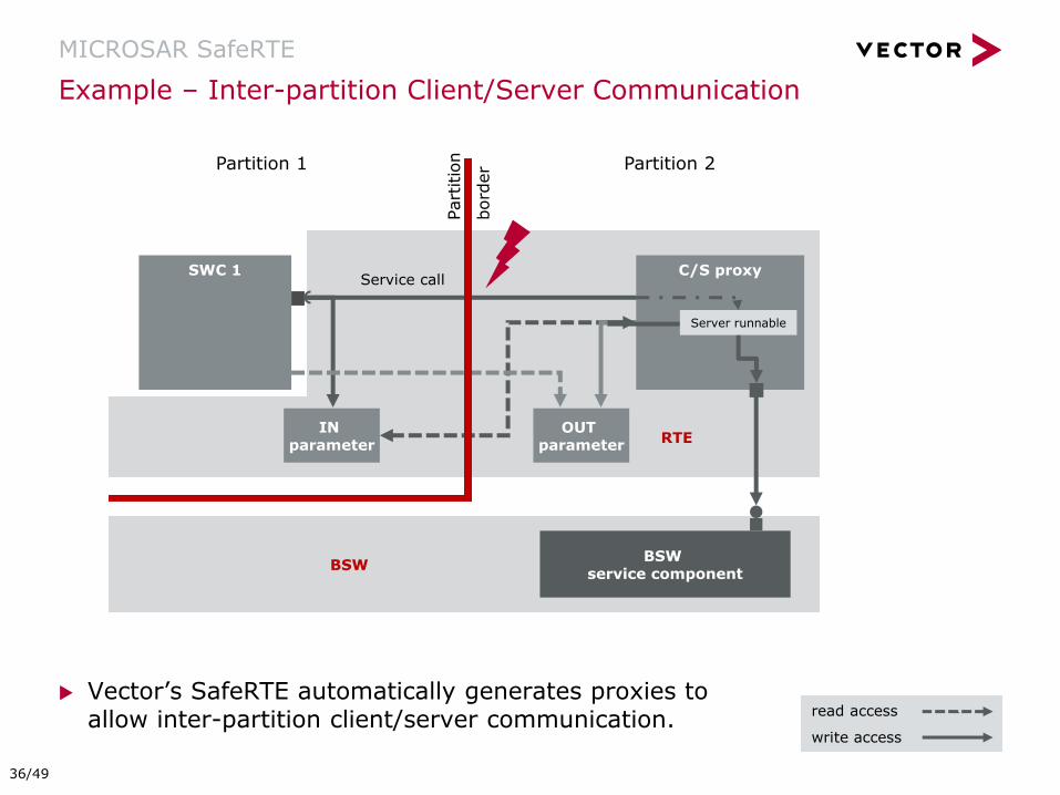
RTE
BSW
Vector’s SafeRTE automatically generates proxies to allow inter-partition client/server communication.
Example – Inter-partition Client/Server Communication
MICROSAR SafeRTE
SWC 1 C/S proxy Service call
Part
itio
n
bord
er
OUT parameter
IN parameter
read access
write access
Partition 2 Partition 1
Server runnable
BSW service component
36/49

Introduction
MICROSAR SafeOS
MICROSAR SafeWDG
MICROSAR SafeE2E
MICROSAR SafeRTE
MICROSAR SafeBSW
Process and Services
Summary
Agenda
37/49
MICROSAR SafeBSW
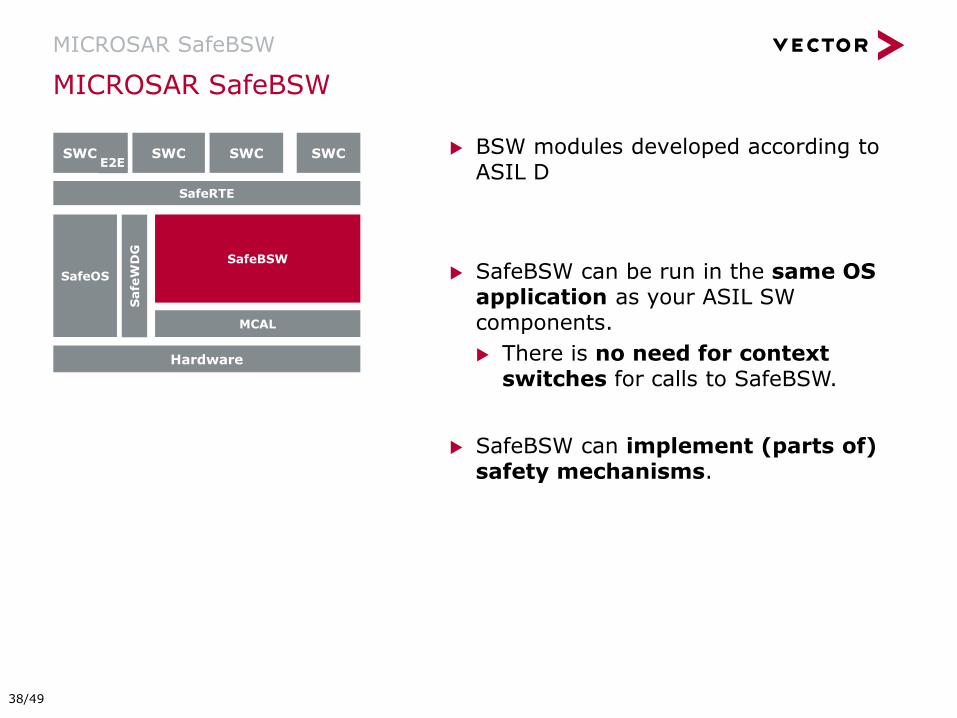
MICROSAR SafeBSW
BSW modules developed according to ASIL D
SafeBSW can be run in the same OS application as your ASIL SW components.
There is no need for context switches for calls to SafeBSW.
SafeBSW can implement (parts of) safety mechanisms.
SafeRTE
SWC
SafeOS
MCAL
SafeBSW
SWC
Hardware
SWC SWC
Safe
WD
G
E2E
38/49

Choosing the Right Approach
MICROSAR SafeBSW
SafeRTE
SWC1 SWC3
RTE
OS BSW
QM Partition ASIL Partition
SWC4 SWC2
runtim
e o
verh
ead
SafeRTE
SWC1 SWC3
RTE
OS BSW
QM Partition ASIL Partition
SWC4 SWC2
Calls from ASIL partition Calls from QM partition
BSW in QM Partition BSW in ASIL Partition
QM BSW (Partitioning Solution)
ASIL BSW (SafeBSW)
Calls to BSW are necessary for e.g. external communication, notifications, …
If the majority of application software has the same ASIL, performance can be boosted by having an ASIL BSW that allows to coexist in the same partition.
[ ] #
#
39/49
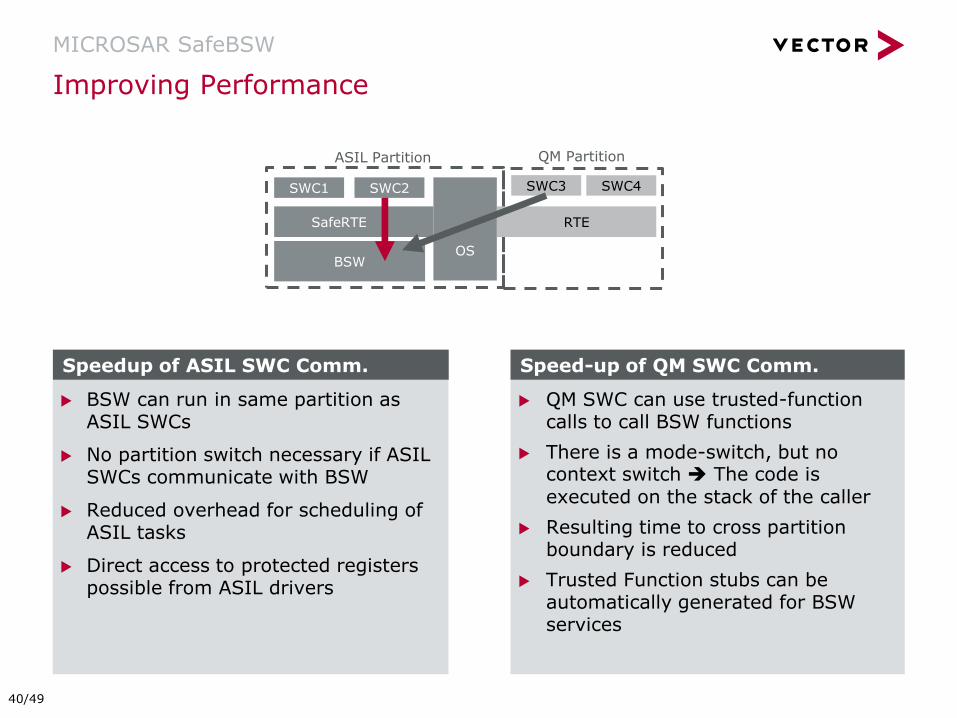
Improving Performance
MICROSAR SafeBSW
SafeRTE
SWC1 SWC3
RTE
OS BSW
QM Partition ASIL Partition
SWC4 SWC2
QM SWC can use trusted-function calls to call BSW functions
There is a mode-switch, but no context switch The code is executed on the stack of the caller
Resulting time to cross partition boundary is reduced
Trusted Function stubs can be automatically generated for BSW services
BSW can run in same partition as ASIL SWCs
No partition switch necessary if ASIL SWCs communicate with BSW
Reduced overhead for scheduling of ASIL tasks
Direct access to protected registers possible from ASIL drivers
Speedup of ASIL SWC Comm. Speed-up of QM SWC Comm.
40/49

SafeOS
Safe
WD
G
SafeRTE
Safety Requirements
MICROSAR SafeBSW
Hardware
MCAL
Communication Services
(CAN, LIN, FlexRay, Ethernet)
Dia
gn
osti
c S
ervic
es
Memory Services
I/O HW
Abstr.
Complex Drivers
System Services
Crypto Services
SWC SWC SWC SWC SWC SWC SWC SWC
Storage of Non-
volatile Data
Initialization and Reset
MAC Generation/Verification
End-to-end Protection Required
ASIL for Coexistence
Only
No
t u
seab
le f
or s
afe
ty
AS
IL f
or C
oexis
ten
ce O
nly
Watchdog/SBC Drivers and Digital I/O
E2E
41/49
Introduction
MICROSAR SafeOS
MICROSAR SafeWDG
MICROSAR SafeE2E
MICROSAR SafeRTE
MICROSAR SafeBSW
Process and Services
Summary
Agenda
42/49
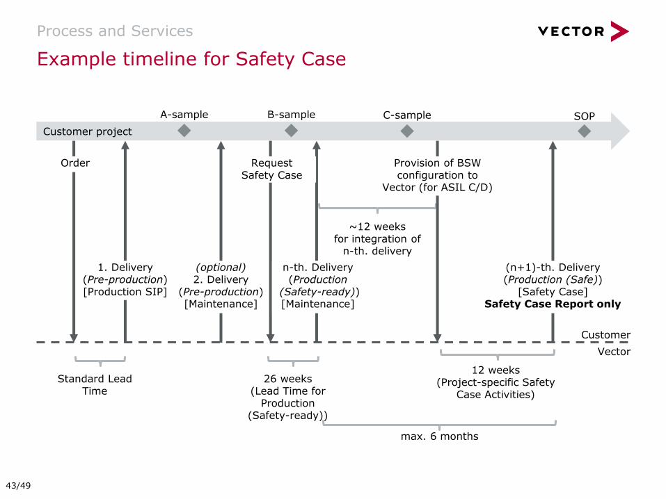
Customer project
Example timeline for Safety Case
Process and Services
1. Delivery (Pre-production) [Production SIP]
(optional) 2. Delivery
(Pre-production) [Maintenance]
A-sample
Customer
Vector
Provision of BSW configuration to
Vector (for ASIL C/D)
12 weeks (Project-specific Safety
Case Activities)
~12 weeks for integration of
n-th. delivery
Request Safety Case
26 weeks (Lead Time for
Production (Safety-ready))
SOP B-sample C-sample
n-th. Delivery (Production
(Safety-ready)) [Maintenance]
(n+1)-th. Delivery (Production (Safe))
[Safety Case] Safety Case Report only
max. 6 months
Standard Lead Time
Order
43/49
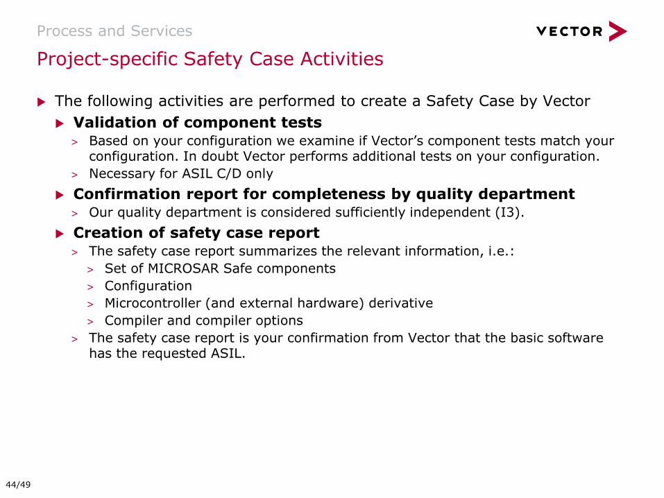
The following activities are performed to create a Safety Case by Vector
Validation of component tests > Based on your configuration we examine if Vector’s component tests match your
configuration. In doubt Vector performs additional tests on your configuration.
> Necessary for ASIL C/D only
Confirmation report for completeness by quality department > Our quality department is considered sufficiently independent (I3).
Creation of safety case report > The safety case report summarizes the relevant information, i.e.:
> Set of MICROSAR Safe components
> Configuration
> Microcontroller (and external hardware) derivative
> Compiler and compiler options
> The safety case report is your confirmation from Vector that the basic software has the requested ASIL.
Project-specific Safety Case Activities
Process and Services
44/49

Additional project specific services can be ordered from Vector:
Development of test specifications and tests to verify the SafeBSW Software Safety Requirements within your context.
Execution of tests using VT System.
Qualification of the I/O Hardware Abstraction.
Qualification of generated executable code, callouts and hooks from BSW.
Qualification of MCALs.
Support for SafeBSW and VT System.
Services in context of SafeBSW
Process and Services
45/49
Introduction
MICROSAR SafeOS
MICROSAR SafeWDG
MICROSAR SafeE2E
MICROSAR SafeRTE
MICROSAR SafeBSW
Process and Services
Summary
Agenda
46/49
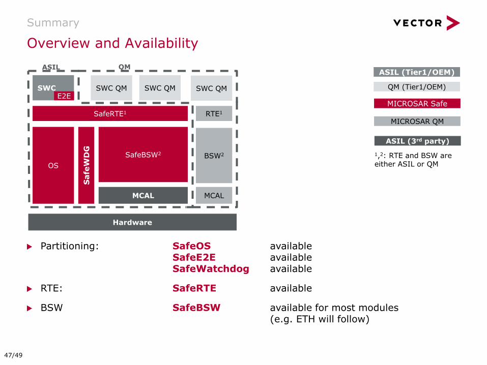
Overview and Availability
Summary
Partitioning: SafeOS available SafeE2E available SafeWatchdog available
RTE: SafeRTE available
BSW SafeBSW available for most modules (e.g. ETH will follow)
QM (Tier1/OEM)
ASIL (Tier1/OEM)
SafeRTE1
SWC SWC QM E2E
OS
MCAL
SafeBSW2
ASIL QM
SWC QM
Hardware
ASIL (3rd party)
MICROSAR Safe
SWC QM
RTE1
BSW2
MCAL
MICROSAR QM
1,2: RTE and BSW are either ASIL or QM
Safe
WD
G
47/49
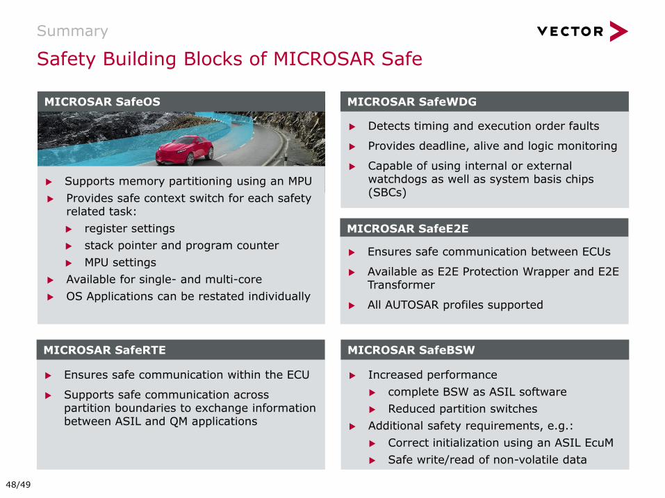
Safety Building Blocks of MICROSAR Safe
Summary
Supports memory partitioning using an MPU
Provides safe context switch for each safety related task:
register settings
stack pointer and program counter
MPU settings
Available for single- and multi-core
OS Applications can be restated individually
Detects timing and execution order faults
Provides deadline, alive and logic monitoring
Capable of using internal or external watchdogs as well as system basis chips (SBCs)
Ensures safe communication between ECUs
Available as E2E Protection Wrapper and E2E Transformer
All AUTOSAR profiles supported
MICROSAR SafeOS MICROSAR SafeWDG
MICROSAR SafeE2E
Ensures safe communication within the ECU
Supports safe communication across partition boundaries to exchange information between ASIL and QM applications
MICROSAR SafeRTE
Increased performance
complete BSW as ASIL software
Reduced partition switches
Additional safety requirements, e.g.:
Correct initialization using an ASIL EcuM
Safe write/read of non-volatile data
MICROSAR SafeBSW
48/49

© 2015. Vector Informatik GmbH. All rights reserved. Any distribution or copying is subject to prior written approval by Vector. V2.02.00 | 2017-06-19
Author: Günther Heling, Jonas Wolf, Markus Oertel Vector Germany
For more information about Vector and our products please visit www.vector.com