embedded and ambient systems 2021. 09. 07
TRANSCRIPT

© BME-MITBudapest University of Technology and EconomicsDepartment of Measurement and Information
T h l
Embedded and Ambient Systems2021. 09. 07.
IntroductionRemark: tomorrow it is practice from 16:15, same room,
recommended to have your notebook with you Simplicity Studio 4 installed (NOT version 5 but 4)

© BME-MIT 2.slide
Preliminaries Embedded and Ambient Systems
o Subject Code: BMEVIMIAC06 (the English course)o Lectures and Practice:
• Lecture: every Tuesday 16:15-18:00• Practice: every odd Wednesday 16:15-18:00 (odd week of
the semester)o Lecturer: Krébesz, Tamás (BME-MIT)
• E-mail: [email protected] • Room: IE.413
o Requirements:• Midterm (Oct. 19. during lecture)• Exam in the exam period
o Web page of the course:• www.mit.bme.hu/eng/oktatas/targyak/VIMIAC06

© BME-MIT 3.slide
Embedded systems Possible definitions
o Those computer-based application systems, that are:• Autonomous in operation• In strong information-based connection with their
physical/technological environmento Such a unit that control or supervise a machine, instrument or
industrial process.o A computer without a keyboard, i.e. every processor-based or
digital unit that is not a PC. The traditional microprocessor-based systems can be
considered embedded systems.
© BME-MIT 4.slide
Embedded systems: examples Examples:
o Consumer electronics: music player, TV, watch, wireless headphone, camera, display, wireless mouse/keyboard
o Handheld devices: mobilephone, GPS, calculatoro Household appliances: washing machine, microwave oven, fridgeo Home automatization: elevators, alarm system, heating control, remote
home surveillanceo Vehicular electronics: ECU, ABS, ESP, assisted steering, remote control,
parking radar, on-board computer, gear control, etc.o Industrial robots, intelligent power supply, engine controlo Ticket machine, ATM, electronic information centero Medical instrument: blood pressure meter, complex diagnostic devices,o Measurement instruments: software defined measuremento Info communication: modem, router, switch

© BME-MIT 5.slide
Developers of embedded systems
Why is it good to learn embedded sysmtes?o Development is done at the edge of the HW-
based and SW-based worlds: the SW developed can acquire direct information from the real physical world and can react into real-world processes.
o Starting from the circuit design through SW development one can get in touch with PCs and higher level information systems.
o Continuously developing industrial field, makes a living for lots of people, new professionals are always needed.

© BME-MIT 6.slide
Example: direct connection with environ. What does it mean ‘being in direct connection
with the physical environment’?o The signals of the environment can be sensed at a low
(abstraction) level, or react to them even in real time.
Example #1: open door?
#define RELAY_ON (0)#define DOOR_BIT (3)...// PORT_A_REG: I/O register nested in memorydoor_is_open = PORT_A_REG & (1 << DOOR_BIT);if (door_is_open){
PORT_A_REG |= 1 << RELAY_ON;}...
PORT
_A_R
EG
0
3
µC
© BME-MIT 7.slide
Example: direct connection with environ.
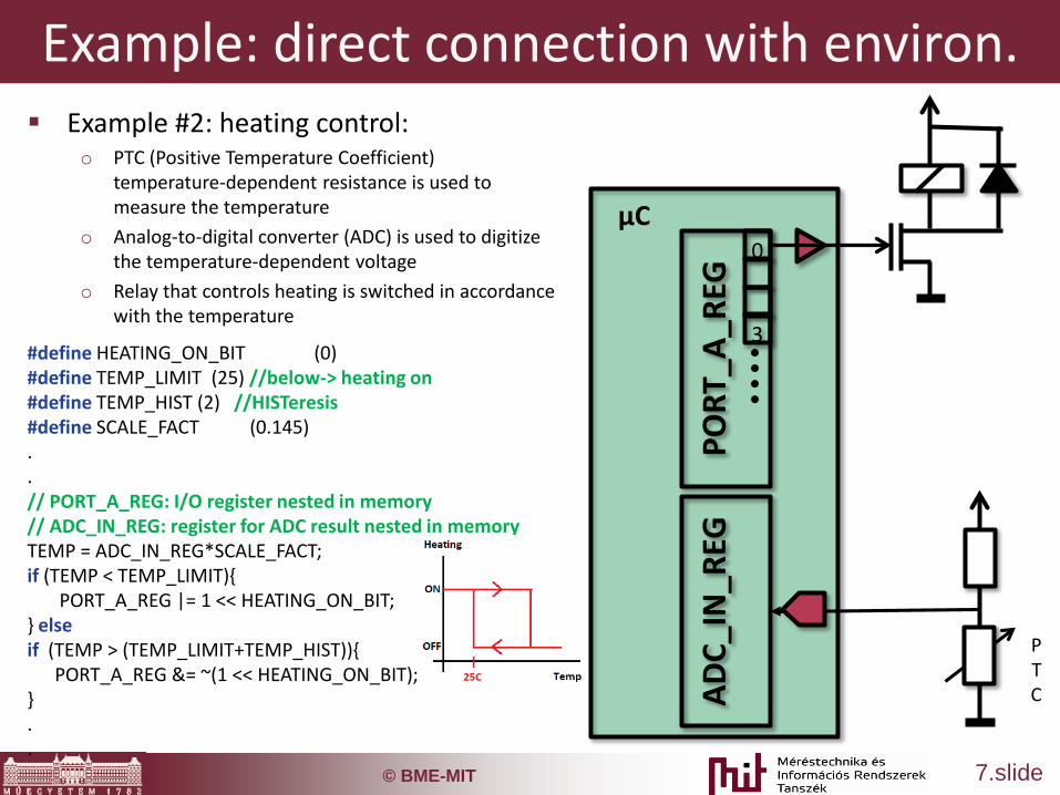
#define HEATING_ON_BIT (0)#define TEMP_LIMIT (25) //below-> heating on#define TEMP_HIST (2) //HISTeresis#define SCALE_FACT (0.145) ..// PORT_A_REG: I/O register nested in memory// ADC_IN_REG: register for ADC result nested in memoryTEMP = ADC_IN_REG*SCALE_FACT;if (TEMP < TEMP_LIMIT){
PORT_A_REG |= 1 << HEATING_ON_BIT;} elseif (TEMP > (TEMP_LIMIT+TEMP_HIST)){
PORT_A_REG &= ~(1 << HEATING_ON_BIT);}..
PORT
_A_R
EG
0
3
µC
ADC_
IN_R
EG
PTC
Example #2: heating control:o PTC (Positive Temperature Coefficient)
temperature-dependent resistance is used to measure the temperature
o Analog-to-digital converter (ADC) is used to digitize the temperature-dependent voltage
o Relay that controls heating is switched in accordance with the temperature

© BME-MIT 8.slide
Evolution of embedded systems Milestones in short
o In the ‘60s: first embedded systems were the controllers used in Apollo program
o ‘70s: popular microprocessor manufactured in high volume (e.g. 8086), first PCs
o ‘80s: microcontrollers with integrated pripheralso ‘90s: handheld devices, embedded systems in
household appliances and System on chip (SoC) ICso From year 2000: embedded systems become part
of everyday life• Ambient systems (around us, in our environment)
o 2010s: connecting embedded systems into complex systems:
• Internet of Things (‘network of embedded systems’)• Cyber Physical Systems (‘embedded systems
exploiting high level of artificial intelligence and integration of databases’)

© BME-MIT 9.slide
Development of embedded systems Development tasks
o HW developmento SW developmento Testingo Tight cooperation among different phases of development
HW developmento Circuit design, implementation, initial testing of operationo ‘Fine-tuning’ of circuit based on development experienceo HW components change the least frequently among system componentso More and more multifunctional devices exist that reuire ‘only’ SW development
SW developmento Plan for SW development is neededo Development of both low- and high level componentso Continuous development, modified dynamically, much more frequently changed
compared to HWo Most of the developers are SW oriented in the embedded field (including testers)
The course focuses on embedded SW development and data processing techniques and systems

© BME-MIT 10.slide
Engineering tasks
© BME-MIT 11.slide
Specialties of embedded SW HW-aware programming Implementation of functionality in SW (either at system- or sourse-
code level) is not enough, awareness is required The specialties of the HW must be considered
o The SWs are for general use but they cannot be totally independent of the platform
Save the resources:o Memory/Datao Processor time
• Complexity of algorithms
o Current consumption
Runtime may be critical (real-time systems) Understanding of the code operation is required: what resources
are used, how much the resources are consumed by the code, etc.

© BME-MIT 12.slide
Architecture of embedded systems Main components of embedded systems:
o Connection to physical world (input):• Sensor/transducer• Signal conditioner• Input devices
o Computing unito Communicationso Actuator

© BME-MIT 13.slide
Input devices Input devices
o Signals from environment, e.g. temperature, luminance,…o Human Interface (HMI)/User Interface (UI), e.g. push button,
touch sensor Definition of ‘sensors’:
o Transducer: transforms a physical quantity into an other type of physical quantity
o Sensor: transforms a physical quantity into an electrical quantity(voltage tipically)
• Either in a direct or indirect way, e.g. strain-gauge: strech turned into resistance turned into voltage
Categories of sensors:o Active: external excitation is needed (e.g. strain-gauge,
thermistor)o Passive: electrical signal is generated by the device at its output
(e.g. photo diode, thermocouple)

© BME-MIT 14.slide
Type of sensors Signals from the environment
o Temperature, luminance, air pressure, humidity, gas presence, airflow, radiation, CCD (charge-coupled device)
Vibroacoustic signalso Microphone, vibration sensor, geophone
Distance, proximity and presence sensorso Ultrsound-based or IR-based distance sensing, PIR (passive
infrared sensor) in motion detectors, reed relay, contact switch, inductive/capacitive proximity sensors
Sensing of positiono Accelerometer, magnetic compass, gyroscope, encoder, linear
variable differential transformer Mechanical signals
o Torque sensor, strain-gauge, force-sensing resistor (FSR)

© BME-MIT 15.slide
Signal conditioning Goals of signal conditioning
o Amplification (e.g. generate 1V from 5mV)o Level matching (e.g. from +/-1V range to 0V…2V range)o Galvanic coupling (e.g. high voltage disturbance)o Impedance matching (e.g. buffer amplifier)o Linearization (non-linear amplifier made linear usually digitally)o Filtering (removing noise)
Nowadays high complexity sensors provides compact form and integration of signal conditioning not only the sensor itself
Further advancement when the sensor provides digital output, i.e., signal conditioning is obviously integrated as well
© BME-MIT 16.slide
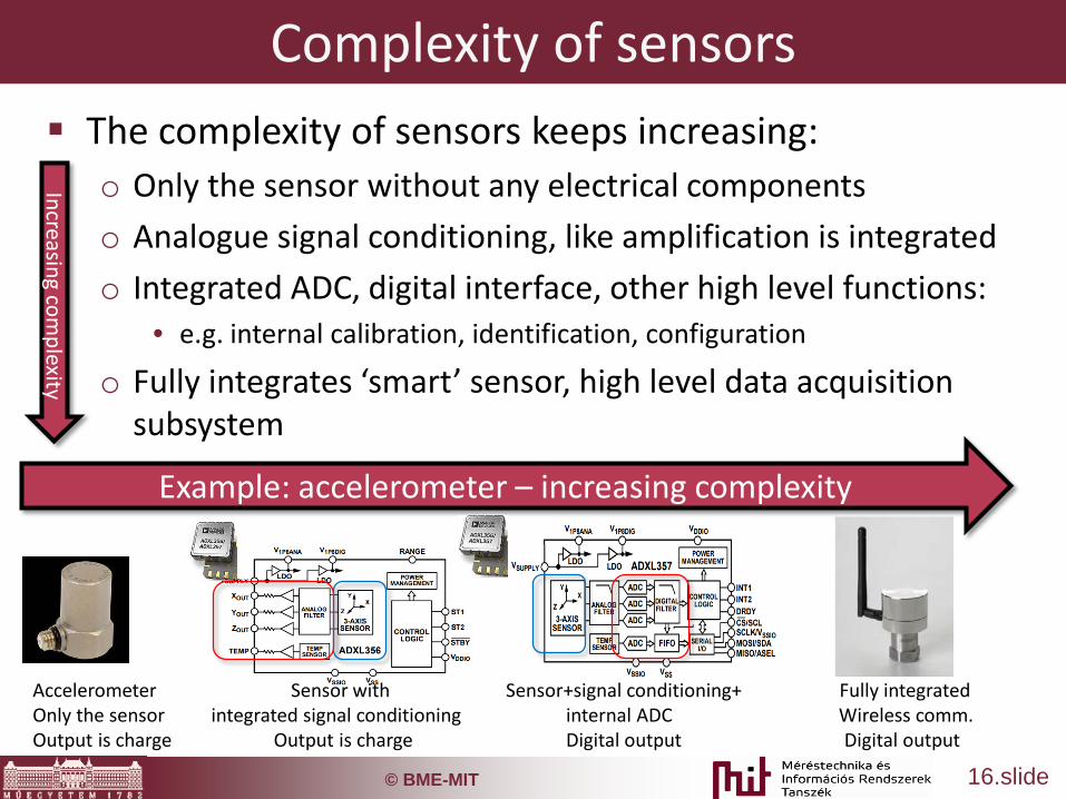
Complexity of sensors The complexity of sensors keeps increasing:
o Only the sensor without any electrical componentso Analogue signal conditioning, like amplification is integratedo Integrated ADC, digital interface, other high level functions:
• e.g. internal calibration, identification, configuration
o Fully integrates ‘smart’ sensor, high level data acquisition subsystem
Example: accelerometer – increasing complexity
Increasing complexity
Accelerometer Sensor with Sensor+signal conditioning+ Fully integrated Only the sensor integrated signal conditioning internal ADC Wireless comm.Output is charge Output is charge Digital output Digital output

© BME-MIT 17.slide
Sensor choice Advantages of high complexity sensors
o Less external componentso Less development timeo Less errorso Many services are integrated
Advantages of low complexity sensorso Cost efficient for high volume manufacturingo No unnecessary functionso Can be tailored for the specific development goal with
special function and features
© BME-MIT 18.slide
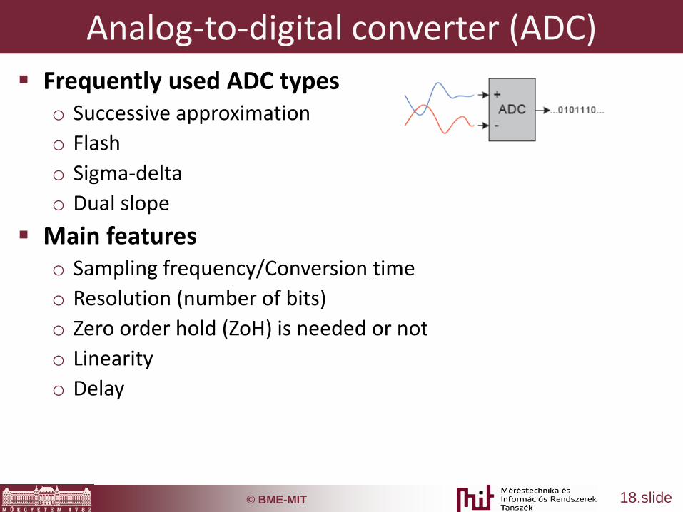
Analog-to-digital converter (ADC) Frequently used ADC types
o Successive approximationo Flasho Sigma-deltao Dual slope
Main featureso Sampling frequency/Conversion timeo Resolution (number of bits)o Zero order hold (ZoH) is needed or noto Linearityo Delay

© BME-MIT 19.slide
ADC typical parameters
Application: scope, RF general use audio accurate

© BME-MIT 20.slide
ADCs in embedded systems External ADC
o In special cases (high resolution, accuracy, speed, low noise)
o Difficulty: HW and SW matching to the uC is a must• Development time and possible errors
Internal ADCo Lots of uC have internal ADC
• In a general purpose uC: 10-16 bit successive approximation• Audio processors: rare, sigma-delta, ~16bit
o Advantages: integrated, matching done, function library offered, template/example codes available

© BME-MIT 21.slide
Control unit Most important types of control units
o uP (Microprocessor) o uC (Microcontroller) o FPGA (Field Programmable Gate Array)o DSP (Digital Signal Processor)o GPU (Graphics Processing Unit)o ASIC (Application-specific Integrated Circuit)
performance
MCU
Task complexity
ARM
FPGA/ASIC
DSP
GPU
performance
MCU
Development time
ARM
FPGA/ASIC
DSPGPU

© BME-MIT 22.slide
Microcontroller Microcontroller = microprocessor + integrated peripherals Peripherals:
o Memory (data and program in separated memory) – SRAM, Flash, ERAMo Timers – measurement of time, event generationo Communications (UART, SPI, I2C, CAN, USB, Ethernet)o ADC and DACo GPIO (General Purpose Input Output)o Energy managemento Debug interface
Typical clock frequency: 1 MHz … 100 MHz+ Choice preferences:
o Availabilityo Adequate complexity for the task, peripherals (e.g. automotive, video, security)o Price (not only chip but development SW and debugger must be considered)o Previous experienceso Support (technical support, forums, function library, development environment,
examples, debug features)o Physical features of the chip
© BME-MIT 23.slide
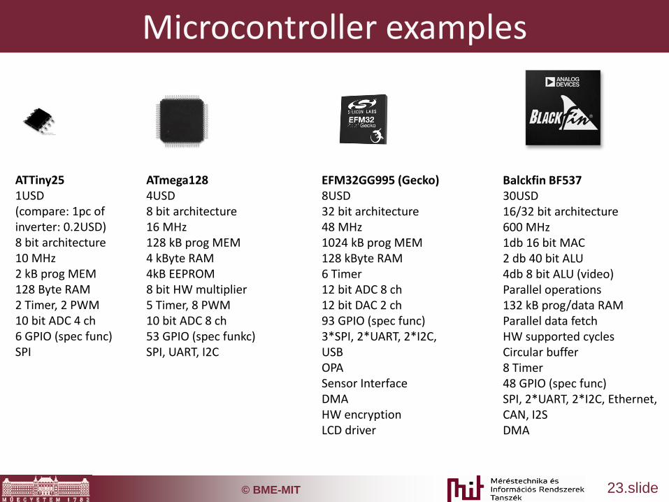
Microcontroller examples
ATTiny251USD(compare: 1pc of inverter: 0.2USD)8 bit architecture10 MHz2 kB prog MEM128 Byte RAM 2 Timer, 2 PWM10 bit ADC 4 ch6 GPIO (spec func)SPI
ATmega1284USD8 bit architecture16 MHz128 kB prog MEM4 kByte RAM 4kB EEPROM8 bit HW multiplier5 Timer, 8 PWM10 bit ADC 8 ch53 GPIO (spec funkc)SPI, UART, I2C
EFM32GG995 (Gecko)8USD32 bit architecture48 MHz1024 kB prog MEM128 kByte RAM 6 Timer12 bit ADC 8 ch12 bit DAC 2 ch93 GPIO (spec func)3*SPI, 2*UART, 2*I2C, USBOPASensor InterfaceDMAHW encryptionLCD driver
Balckfin BF53730USD16/32 bit architecture600 MHz1db 16 bit MAC2 db 40 bit ALU4db 8 bit ALU (video)Parallel operations132 kB prog/data RAMParallel data fetchHW supported cyclesCircular buffer8 Timer48 GPIO (spec func)SPI, 2*UART, 2*I2C, Ethernet, CAN, I2SDMA

© BME-MIT 24.slide
FPGA (Field Programmable Gate Array) Circuit of general logic cells/gates (combinatorial and sequential logic) The logical relationship among logic gates is programmable Flexible: no new circuit is needed when functionality is modified – ‘only’ the SW
has to be replaced Parallelism is inherently supported: one SW defined component can be duplicated
‘endlessly’ (the limit is the number of logic cells in the FPGA unit) Traditional FPGA development is difficult:
o Development requires highly experienced professionals o The functionality has to be implemented at a low level (like shift register), therefore
time consuming – nowadays higher level modules are readily available Used for high computation load, fast or parallel needs (high sampling rate,
multiple inputs, RF, video signal processing)
© BME-MIT 25.slide
Digital signal processors (DSP) Special HW components and architectures to speed up computation, like:
o MAC (Multiply and accumulate: a+=x*y)o Circular buffero Parallel memory access to several memory blockso HW supported loopso Even floating point multiplication in one CLK cycleo HW supported division and extraction of roots,…
Applications:o Multimedia: compressing, effects, coding (e.g. MP3, JPG, MP4), equalizer,
noise filteringo Control systems: engine control, state observer, feedback systemso Math operations: mtx multiplication, trigonometrical functionso Measurements: noise filtering, parameter estimationo Info comm: modulation/demodulation, coding, compression
More and more DSP functions appear in general purpose uC

© BME-MIT 26.slide
Hybrid solutions Several types of processing units integrated
into one application Tasks can be decomposed for the most
appropriate computing type:o Decoding digital graphic information by FPGA or
DSP in a TVo uC-based handling of remote controller and
menu system
System containing several types of processing units can be integrared into a single IC (system-on-chip: SoC) :o Soft-core processors to be downloaded to an
FPGA are availableo A uC can be integrated into an FPGA

© BME-MIT 27.slide
Hybrid solutions Analog Devices SC589:
o 2 pcs DSP core: computational taskso 1 pc ARM cortex-A5: general tasks, e.g. communications,
peripheral handling, etc.

© BME-MIT 28.slide
Communications Fully integrated
o E.g. SPI, USB Integrated comm protocol + external level matching
o pl.: UART + RS232 level matching: logical levels transformed into +/-3V…25V range
External peripherals (Ethernet, CAN, WiFi, Bluetooth, ZigBee)
SW implementation is possibleo Change of GPIO pins in SWo Timing is critical since background processes may
violate timings

© BME-MIT 29.slide
Communications units, examples TRF6900 (TI)
o Bit level communications (‘wireless wire’)
IA4420 (Silabs)o Byte level communications
CC2420 (TI)o Packet level commo Automatic receiver detection
ESP8266 o WiFi modulo Integrated protocol stack
Some uCs are available with integrated RF module Complex unit offers shorter development time, but special
functionality may not be implemented or can be a hard task