ellis patents cable cleats, clamps & hangers - catalogue
TRANSCRIPT
ELECTRICAL PRODUCT CATALOGUE
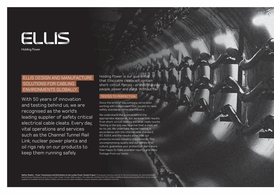
Holding Power is our guarantee that Ellis cable cleats will contain short-circuit forces – protecting your people, power and plant. Without fail.
TESTED TO PERFECTION
Since the birth of the company, we’ve been working with independent test houses to raise safety standards within the industry.
We understand the science behind the appropriate standards, but we know that results from short-circuit testing are what really counts. Testing is the only way to prove that a cleat will do its job. We undertake regular testing in accordance with the international standard IEC 61914, and the results show that our products exceed industry requirements. This uncompromising quality and our ‘safety fi rst’ culture, guarantee your protection. We’re more than happy to make available reports and video footage from our tests.
ELLIS DESIGN AND MANUFACTURE SOLUTIONS FOR CABLING ENVIRONMENTS GLOBALLY.
With 50 years of innovation and testing behind us, we are recognised as the world’s leading supplier of safety critical electrical cable cleats. Every day, vital operations and services such as the Channel Tunnel Rail Link, nuclear power plants and oil rigs rely on our products to keep them running safely.
Balfour Beatty - Power Transmission and Distribution on the London Power Tunnels Project. Photograph showing a section of the tunnel between St Johns Wood and Kensal Green Substations, part of the London Power Tunnels 400kV project. The cable was installed onto Ellis Centaur saddles and secured using Ellis short circuit straps supplied to Sudkabel directly. Balfour Beatty carried out the cable installation using its bespoke cable installation machine.

/32www.ellispatents.co.uk
CONTENTS
Alpha™ 4/5
Emperor™ 6/7
Vulcan+™ 8/9
Flexi-cleat™ 10
Flexi-strap™ 11
Protect™ 12
Matrix™ 13
Vari-cleat™ 14/15
Atlas™ 16/17
Colossus™ 18/19
Centaur® 20/21
Cable Guide Clamp™ 22/23
Phoenix® 24/25
One & Two Hole Cableclamps - Aluminium 26/27
One & Two Hole Cableclamps - Non Metallic 28/29
Heavy Duty Single Bolt Fixing 30
Triplex Cable Surround 31
Industrial Cableclamp 32
Elite Range-Taker Cableclamp 32
Earthing Strip Clip 33
Cable Conduit Clip 33
Framing Channel Accessories 34/35
Specialist Cable Fixings for Utilities 36/37
Jointers’ Tools 38/39
Cable Hangers 40
Suspension Hooks 41
Bespoke Solutions and Products 42
Products are supplied without mounting fi xings.
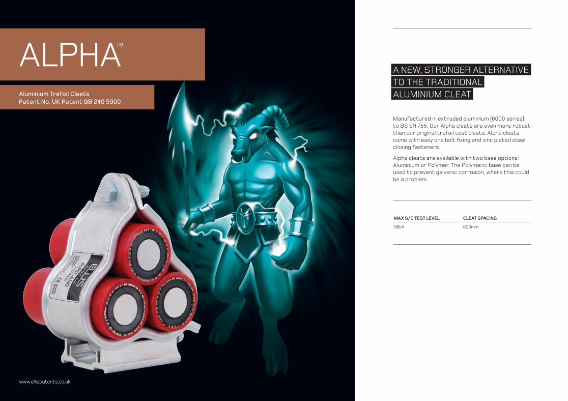
ALPHA™
Aluminium Trefoil CleatsPatent No. UK Patent GB 240 5900
www.ellispatents.co.uk
A NEW, STRONGER ALTERNATIVE TO THE TRADITIONALALUMINIUM CLEAT
Manufactured in extruded aluminium (6000 series) to BS EN 755. Our Alpha cleats are even more robust than our original trefoil cast cleats. Alpha cleats come with easy one bolt fi xing and zinc plated steel closing fasteners.
Alpha cleats are available with two base options: Aluminium or Polymer. The Polymeric base can be used to prevent galvanic corrosion, where this could be a problem.
MAX S/C TEST LEVEL CLEAT SPACING
96kA 600mm

/54www.ellispatents.co.ukALP05-ANO 4CG8
The Alpha Cable Cleats are compliant with the requirement of London Underground Standard 1-085. Product Register No. 360.
(American Bureau of Shipping)Type Approval.
Part No. Part No. Trefoil Cable Range Dimensions mmFixing Holes
WeightgAluminium
BaseLSF Zero Halogen Base
Min Dia. mm
Max Dia. mm
W H D
ALP01-AN0 ALP01-AN1 23.2 25.1 76 93 48.5 1 x M10 168
ALP02-AN0 ALP02-AN1 25.1 27.1 79 96 48.5 1 x M10 178
ALP03-AN0 ALP03-AN1 27.1 29.3 82 101 48.5 1 x M10 185
ALP04-AN0 ALP04-AN1 29.3 31.7 86 105 48.5 1 x M10 195
ALP05-AN0 ALP05-AN1 31.7 34.2 91 110 48.5 1 x M10 205
ALP06-AN0 ALP06-AN1 34.2 37.0 96 116 48.5 1 x M10 217
ALP07-AN0 ALP07-AN1 37.0 40.0 101 121 48.5 1 x M10 229
ALP08-AN0 ALP08-AN1 40.0 43.2 106 127 48.5 1 x M10 241
ALP09-AN0 ALP09-AN1 43.2 46.7 113 134 48.5 1 x M10 255
ALP10-AN0 ALP10-AN1 46.7 50.5 119 141 48.5 1 x M10 272
ALP11-AN0 ALP11-AN1 50.5 54.6 127 148 48.5 1 x M10 288
ALP12-AN0 ALP12-AN1 54.6 59.0 135 156 48.5 1 x M10 307
ALP13-AN0 ALP13-AN1 59.0 63.8 144 165 48.5 1 x M10 327
ALP14-AN0 ALP14-AN1 63.8 69.0 153 175 48.5 1 x M10 348
ALP15-AN0 ALP15-AN1 69.0 74.6 163 186 48.5 1 x M10 372
Special options:Single versions available to specifi c cable diameters.
Polyester coating and alternative fasteners are available on request.
Aluminium basePolymer base
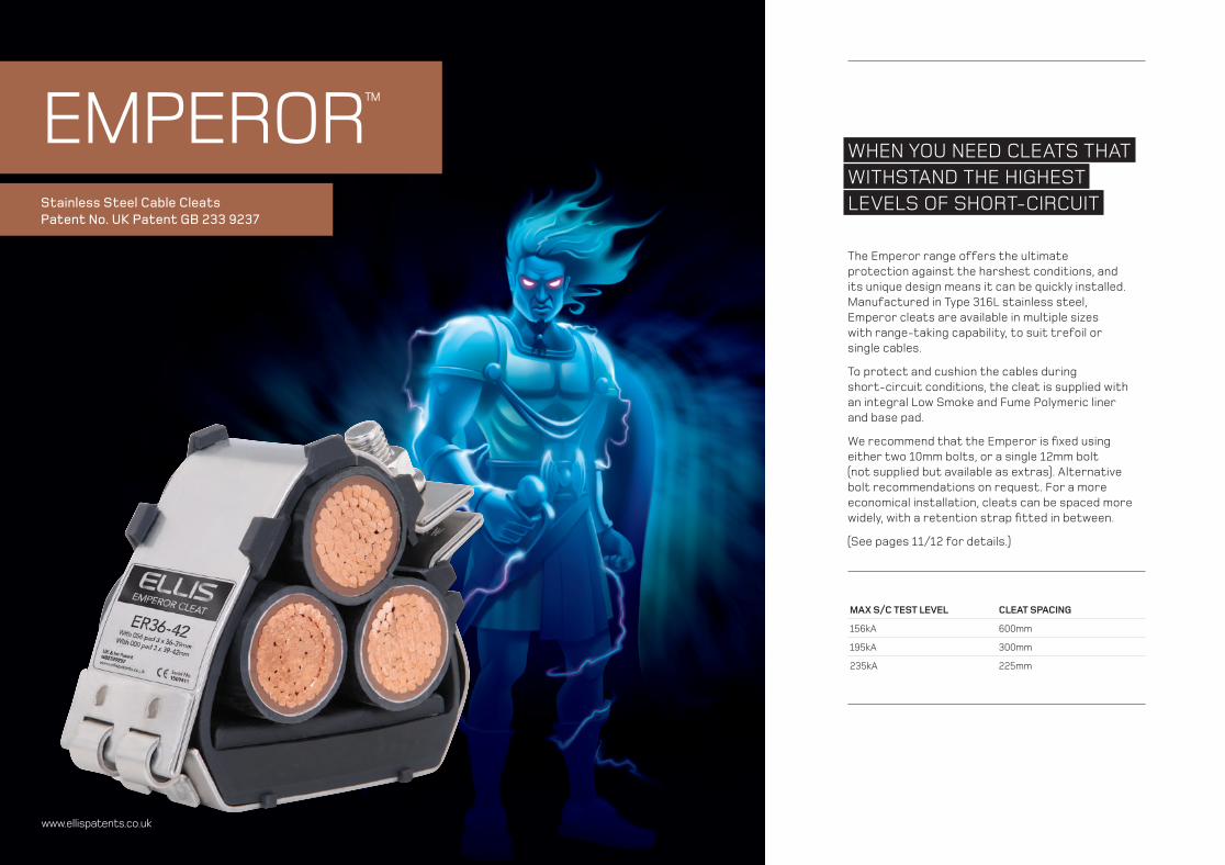
EMPEROR™
Stainless Steel Cable CleatsPatent No. UK Patent GB 233 9237
www.ellispatents.co.uk
WHEN YOU NEED CLEATS THATWITHSTAND THE HIGHESTLEVELS OF SHORT-CIRCUIT
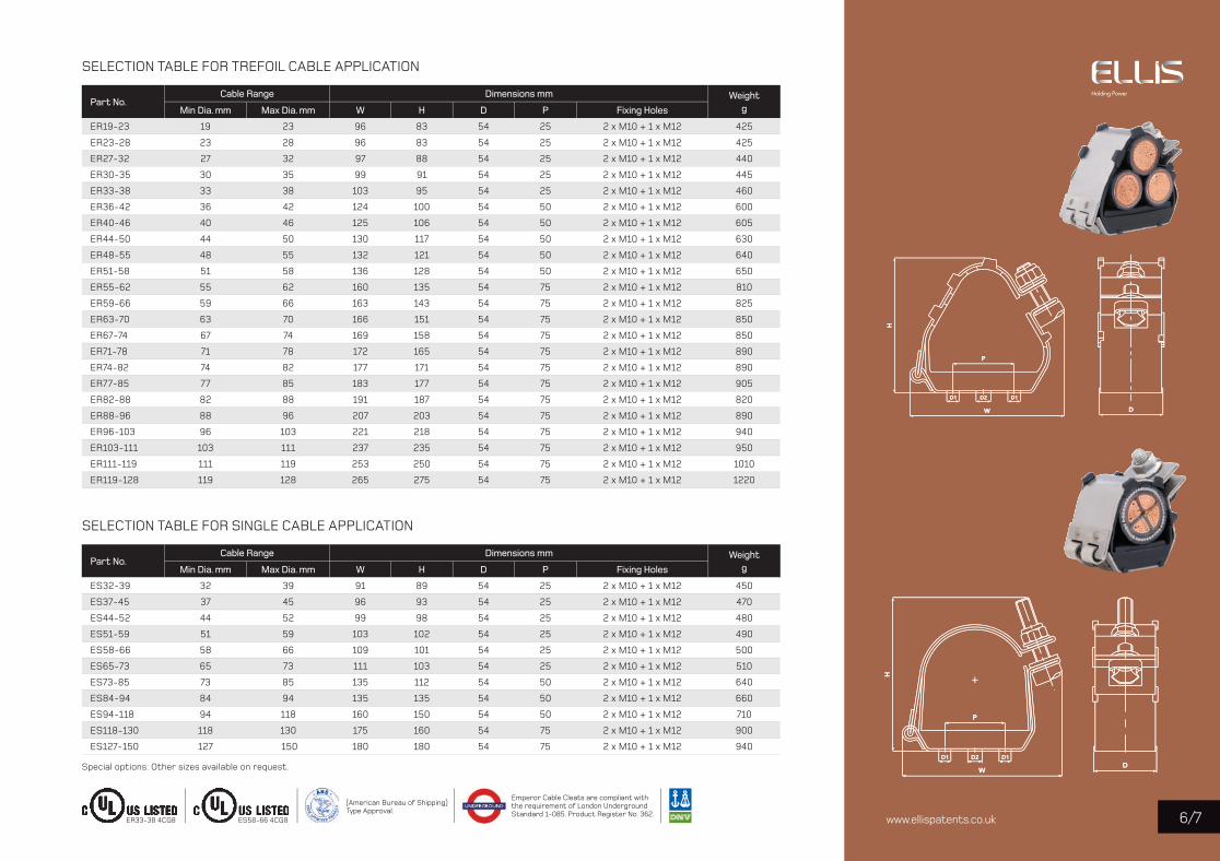
The Emperor range offers the ultimate protection against the harshest conditions, and its unique design means it can be quickly installed. Manufactured in Type 316L stainless steel, Emperor cleats are available in multiple sizes with range-taking capability, to suit trefoil or single cables.
To protect and cushion the cables during short-circuit conditions, the cleat is supplied with an integral Low Smoke and Fume Polymeric liner and base pad.
We recommend that the Emperor is fi xed using either two 10mm bolts, or a single 12mm bolt (not supplied but available as extras). Alternative bolt recommendations on request. For a more economical installation, cleats can be spaced more widely, with a retention strap fi tted in between.
(See pages 11/12 for details.)
MAX S/C TEST LEVEL CLEAT SPACING
156kA 600mm
195kA 300mm
235kA 225mm
/76www.ellispatents.co.uk
SELECTION TABLE FOR TREFOIL CABLE APPLICATION
Part No. Cable Range Dimensions mm Weight
gMin Dia. mm Max Dia. mm W H D P Fixing Holes
ER19-23 19 23 96 83 54 25 2 x M10 + 1 x M12 425
ER23-28 23 28 96 83 54 25 2 x M10 + 1 x M12 425
ER27-32 27 32 97 88 54 25 2 x M10 + 1 x M12 440
ER30-35 30 35 99 91 54 25 2 x M10 + 1 x M12 445
ER33-38 33 38 103 95 54 25 2 x M10 + 1 x M12 460
ER36-42 36 42 124 100 54 50 2 x M10 + 1 x M12 600
ER40-46 40 46 125 106 54 50 2 x M10 + 1 x M12 605
ER44-50 44 50 130 117 54 50 2 x M10 + 1 x M12 630
ER48-55 48 55 132 121 54 50 2 x M10 + 1 x M12 640
ER51-58 51 58 136 128 54 50 2 x M10 + 1 x M12 650
ER55-62 55 62 160 135 54 75 2 x M10 + 1 x M12 810
ER59-66 59 66 163 143 54 75 2 x M10 + 1 x M12 825
ER63-70 63 70 166 151 54 75 2 x M10 + 1 x M12 850
ER67-74 67 74 169 158 54 75 2 x M10 + 1 x M12 850
ER71-78 71 78 172 165 54 75 2 x M10 + 1 x M12 890
ER74-82 74 82 177 171 54 75 2 x M10 + 1 x M12 890
ER77-85 77 85 183 177 54 75 2 x M10 + 1 x M12 905
ER82-88 82 88 191 187 54 75 2 x M10 + 1 x M12 820
ER88-96 88 96 207 203 54 75 2 x M10 + 1 x M12 890
ER96-103 96 103 221 218 54 75 2 x M10 + 1 x M12 940
ER103-111 103 111 237 235 54 75 2 x M10 + 1 x M12 950
ER111-119 111 119 253 250 54 75 2 x M10 + 1 x M12 1010
ER119-128 119 128 265 275 54 75 2 x M10 + 1 x M12 1220
SELECTION TABLE FOR SINGLE CABLE APPLICATION
Part No. Cable Range Dimensions mm Weight
gMin Dia. mm Max Dia. mm W H D P Fixing Holes
ES32-39 32 39 91 89 54 25 2 x M10 + 1 x M12 450
ES37-45 37 45 96 93 54 25 2 x M10 + 1 x M12 470
ES44-52 44 52 99 98 54 25 2 x M10 + 1 x M12 480
ES51-59 51 59 103 102 54 25 2 x M10 + 1 x M12 490
ES58-66 58 66 109 101 54 25 2 x M10 + 1 x M12 500
ES65-73 65 73 111 103 54 25 2 x M10 + 1 x M12 510
ES73-85 73 85 135 112 54 50 2 x M10 + 1 x M12 640
ES84-94 84 94 135 135 54 50 2 x M10 + 1 x M12 660
ES94-118 94 118 160 150 54 50 2 x M10 + 1 x M12 710
ES118-130 118 130 175 160 54 75 2 x M10 + 1 x M12 900
ES127-150 127 150 180 180 54 75 2 x M10 + 1 x M12 940
Special options: Other sizes available on request.
ER33-38 4CG8 ES58-66 4CG8
Emperor Cable Cleats are compliant with the requirement of London UndergroundStandard 1-085. Product Register No. 362.
(American Bureau of Shipping)Type Approval.

VULCAN+™
Stainless Steel Cable CleatsPatent No. UK Patent GB 236 1029
www.ellispatents.co.uk
WHEN YOU NEED CLEATS THAT WITHSTAND MODERATELEVELS OF SHORT-CIRCUIT
Our Vulcan+ cleats have a unique compact design so they can be easily installed, even when space is limited. Vulcan+ cleats are available in multiple sizes with range-taking capability, to suit trefoil, single, quad or bundled cables.
Manufactured in Type 316L stainless steel, Vulcan+ offer excellent protection against the harshest environmental conditions. To protect and cushion the cables during short-circuit conditions, the cleat comes with an integral Low Smoke and Fume Zero Halogen Polymeric liner and base pad.
We recommend fi xing VRT+ using one 10mm bolt for sizes 00 to 09, and one or two 10mm bolts for sizes 10 to 20. For VRQ+ use one 10mm bolt for sizes 01 to 06, and one or two 10mm bolts for sizes 07 to 09 (not supplied but available as extras). Alternative bolt recommendations on request. For a more economical installation, cleats can be spaced more widely, with a retention strap fi tted in between.
(See pages 11/12 for details.)
MAX S/C TEST LEVEL CLEAT SPACING
104kA 600mm
132kA 300mm

/98www.ellispatents.co.ukVRT+06 4CG8 VRQ+03 4CG8
Vulcan VRT+ Cable Cleats are compliant with the requirement of London Underground Standard 1-085. Product Register No. 361.
(American Bureau of Shipping)Type Approval.
SELECTION TABLE FOR TREFOIL AND SINGLE CABLE APPLICATION
Part No. Trefoil Cable Range Single Cable Range Dimensions mm Weight
gMin Dia. mm Max Dia. mm Min Dia. mm Max Dia. mm W H D P Fixing Holes
VRT+00 19 24 30 42 60 93 54 n/a 1 x M10 251
VRT+01 23 28 38 50 63 98 54 n/a 1 x M10 258
VRT+02 27 32 43 58 72 106 54 n/a 1 x M10 269
VRT+03 30 35 49 64 79 112 54 n/a 1 x M10 279
VRT+04 33 38 55 70 85 118 54 n/a 1 x M10 284
VRT+05 36 42 58 75 96 125 54 n/a 1 x M10 319
VRT+06 40 46 63 84 105 133 54 n/a 1 x M10 331
VRT+07 44 50 73 90 112 140 54 n/a 1 x M10 391
VRT+08 48 55 83 100 121 149 54 n/a 1 x M10 405
VRT+09 51 58 86 104 126 154 54 n/a 1 x M10 411
VRT+10 55 62 88 110 134 162 54 50 3 x M10 442
VRT+11 59 66 90 115 143 170 54 50 3 x M10 453
VRT+12 63 70 100 125 152 177 54 50 3 x M10 460
VRT+13 67 74 107 132 161 185 54 75 3 x M10 524
VRT+14 71 78 120 145 169 192 54 75 3 x M10 536
VRT+15 74 82 125 150 176 199 54 75 3 x M10 542
VRT+16 77 85 132 153 183 205 54 75 3 x M10 544
VRT+17 81 89 136 156 190 216 54 75 3 x M10 618
VRT+18 85 93 139 159 200 225 54 75 3 x M10 628
VRT+19 89 97 142 162 200 235 54 75 3 x M10 637
VRT+20 93 101 150 170 215 240 54 75 3 x M10 646
SELECTION TABLE FOR QUAD CABLE APPLICATION
Part No. Cable Range Dimensions mm Weight
gMin Dia. mm Max Dia. mm W H D P Fixing Holes
VRQ+01 23 25 68 110 54 n/a 1 x M10 284
VRQ+02 26 27 70 113 54 n/a 1 x M10 286
VRQ+03 28 31 78 128 54 n/a 1 x M10 318
VRQ+3A 31 35 90 138 54 n/a 1 x M10 350
VRQ+04 35 42 103 148 54 n/a 1 x M10 378
VRQ+05 43 47 120 165 54 n/a 1 x M10 452
VRQ+06 48 50 121 170 54 n/a 1 x M10 467
VRQ+07 51 57 140 190 54 50 3 x M10 486
VRQ+08 58 63 150 200 54 50 3 x M10 499
VRQ+09 64 70 170 218 54 75 3 x M10 581
D1 D2 D1
P
W
H
D
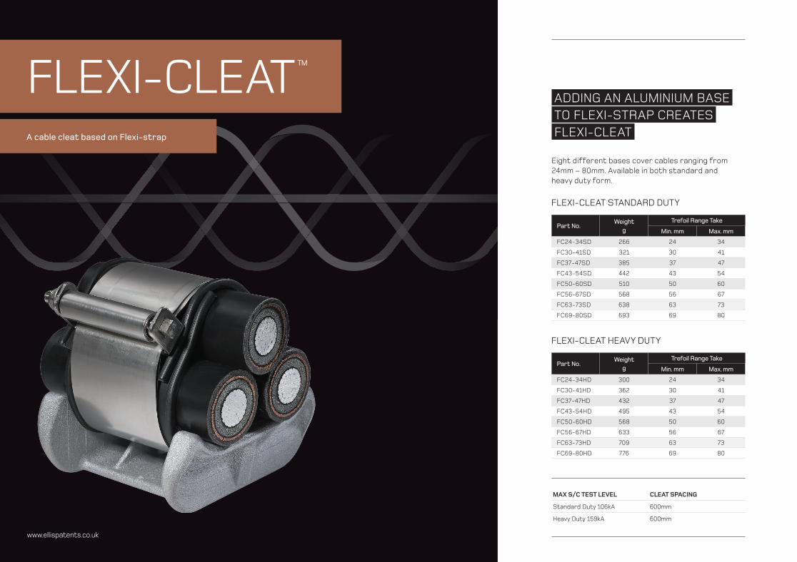
ADDING AN ALUMINIUM BASETO FLEXI-STRAP CREATESFLEXI-CLEAT
Eight different bases cover cables ranging from 24mm – 80mm. Available in both standard and heavy duty form.
FLEXI-CLEAT™
A cable cleat based on Flexi-strap
www.ellispatents.co.uk
FLEXI-CLEAT STANDARD DUTY
Part No. Weight
g Trefoil Range Take
Min. mm Max. mm
FC24-34SD 266 24 34
FC30-41SD 321 30 41
FC37-47SD 385 37 47
FC43-54SD 442 43 54
FC50-60SD 510 50 60
FC56-67SD 568 56 67
FC63-73SD 638 63 73
FC69-80SD 693 69 80
FLEXI-CLEAT HEAVY DUTY
Part No. Weight
g Trefoil Range Take
Min. mm Max. mm
FC24-34HD 300 24 34
FC30-41HD 362 30 41
FC37-47HD 432 37 47
FC43-54HD 495 43 54
FC50-60HD 568 50 60
FC56-67HD 633 56 67
FC63-73HD 709 63 73
FC69-80HD 776 69 80
MAX S/C TEST LEVEL CLEAT SPACING
Standard Duty 106kA 600mm
Heavy Duty 159kA 600mm
ww
w.e
llispa
tent
s.co
.uk
/1110
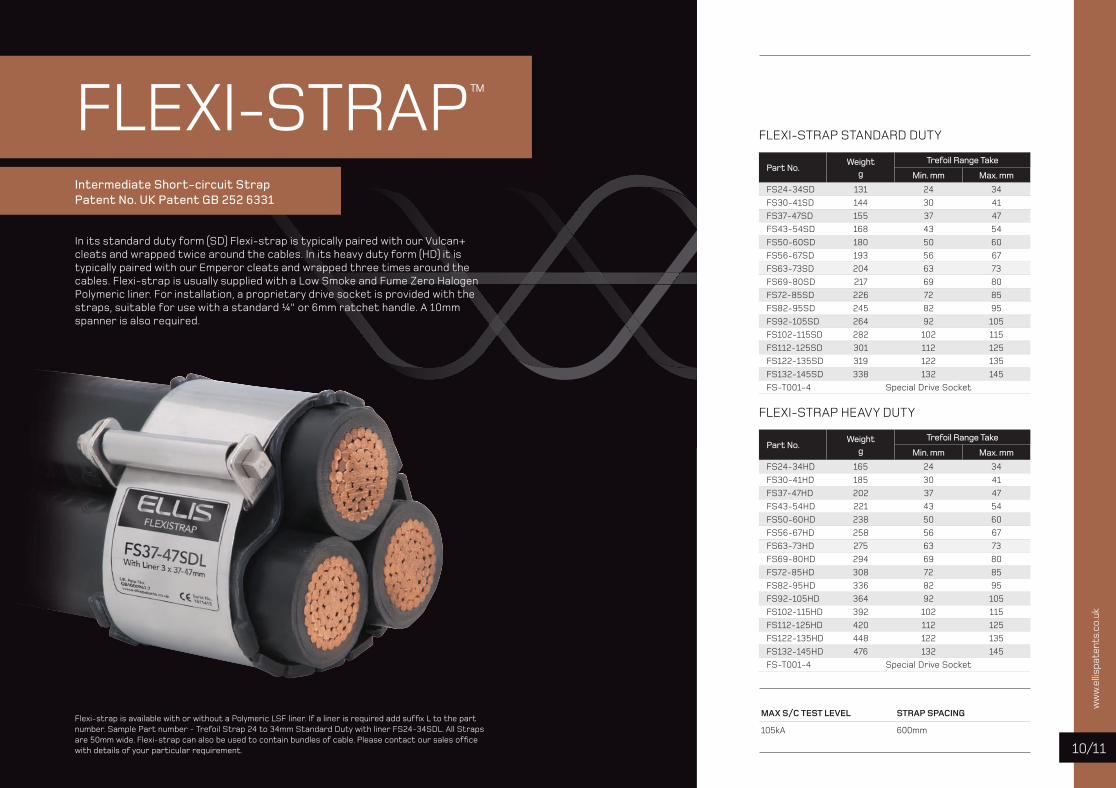
FLEXI-STRAP™
Intermediate Short-circuit StrapPatent No. UK Patent GB 252 6331
Flexi-strap is available with or without a Polymeric LSF liner. If a liner is required add suffi x L to the part number. Sample Part number - Trefoil Strap 24 to 34mm Standard Duty with liner FS24-34SDL. All Straps are 50mm wide. Flexi-strap can also be used to contain bundles of cable. Please contact our sales offi ce with details of your particular requirement.
FLEXI-STRAP STANDARD DUTY
Part No. Weight
g Trefoil Range Take
Min. mm Max. mm
FS24-34SD 131 24 34FS30-41SD 144 30 41FS37-47SD 155 37 47FS43-54SD 168 43 54FS50-60SD 180 50 60FS56-67SD 193 56 67FS63-73SD 204 63 73FS69-80SD 217 69 80FS72-85SD 226 72 85FS82-95SD 245 82 95FS92-105SD 264 92 105FS102-115SD 282 102 115FS112-125SD 301 112 125FS122-135SD 319 122 135FS132-145SD 338 132 145FS-T001-4 Special Drive Socket
FLEXI-STRAP HEAVY DUTY
Part No. Weight
g Trefoil Range Take
Min. mm Max. mm
FS24-34HD 165 24 34FS30-41HD 185 30 41FS37-47HD 202 37 47FS43-54HD 221 43 54FS50-60HD 238 50 60FS56-67HD 258 56 67FS63-73HD 275 63 73FS69-80HD 294 69 80FS72-85HD 308 72 85FS82-95HD 336 82 95FS92-105HD 364 92 105FS102-115HD 392 102 115FS112-125HD 420 112 125FS122-135HD 448 122 135FS132-145HD 476 132 145FS-T001-4 Special Drive Socket
MAX S/C TEST LEVEL STRAP SPACING
105kA 600mm
In its standard duty form (SD) Flexi-strap is typically paired with our Vulcan+ cleats and wrapped twice around the cables. In its heavy duty form (HD) it is typically paired with our Emperor cleats and wrapped three times around the cables. Flexi-strap is usually supplied with a Low Smoke and Fume Zero Halogen Polymeric liner. For installation, a proprietary drive socket is provided with the straps, suitable for use with a standard ¼" or 6mm ratchet handle. A 10mm spanner is also required.
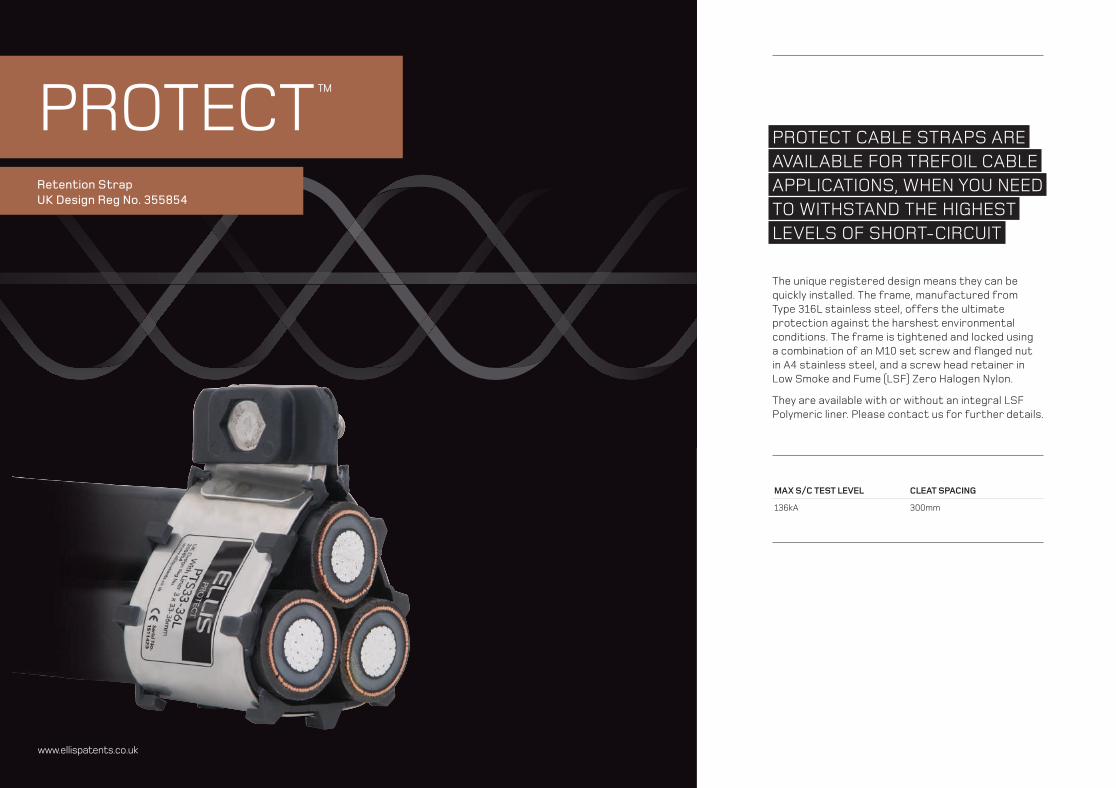
PROTECT™
Retention Strap UK Design Reg No. 355854
www.ellispatents.co.uk
PROTECT CABLE STRAPS ARE AVAILABLE FOR TREFOIL CABLE APPLICATIONS, WHEN YOU NEEDTO WITHSTAND THE HIGHESTLEVELS OF SHORT-CIRCUIT
The unique registered design means they can be quickly installed. The frame, manufactured from Type 316L stainless steel, offers the ultimate protection against the harshest environmental conditions. The frame is tightened and locked using a combination of an M10 set screw and fl anged nut in A4 stainless steel, and a screw head retainer in Low Smoke and Fume (LSF) Zero Halogen Nylon.
They are available with or without an integral LSF Polymeric liner. Please contact us for further details.
MAX S/C TEST LEVEL CLEAT SPACING
136kA 300mm
ww
w.e
llispa
tent
s.co
.uk
/1312
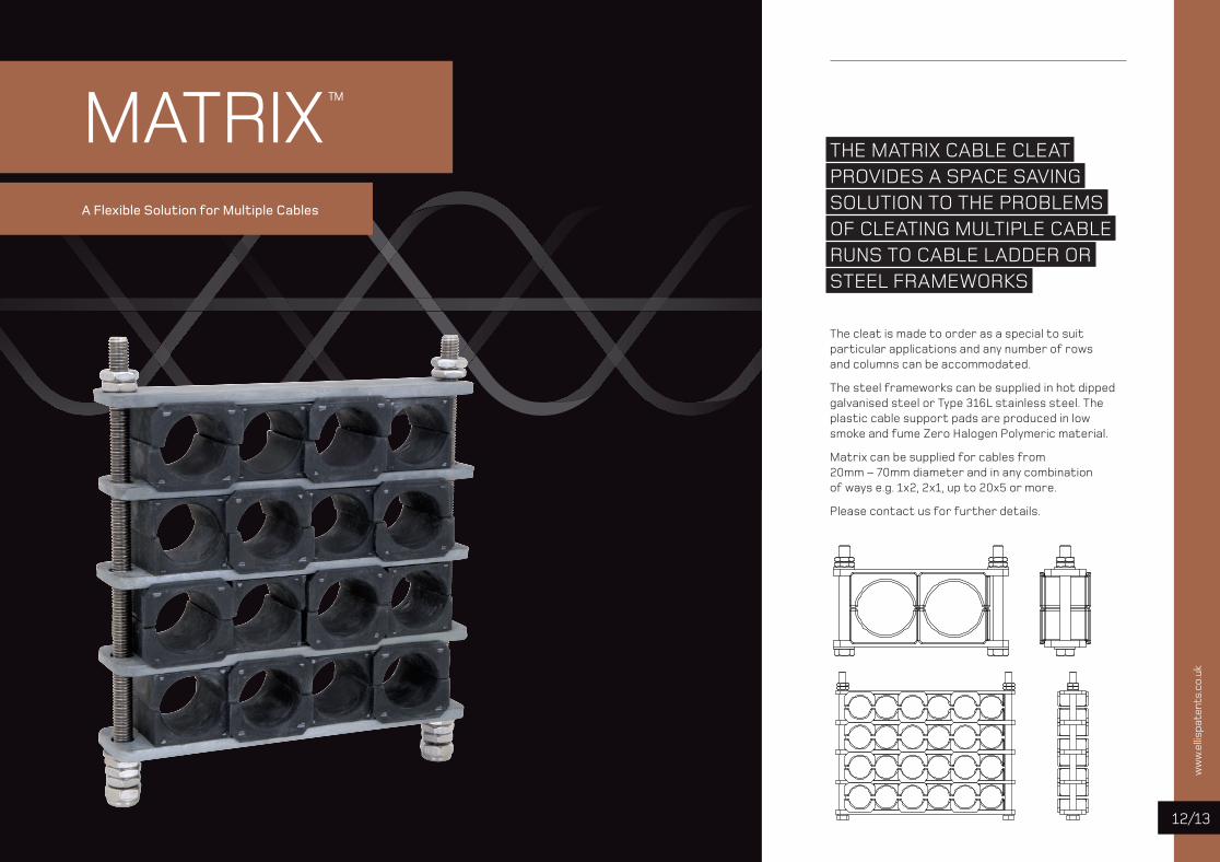
MATRIX™
A Flexible Solution for Multiple Cables
THE MATRIX CABLE CLEAT PROVIDES A SPACE SAVING SOLUTION TO THE PROBLEMS OF CLEATING MULTIPLE CABLERUNS TO CABLE LADDER OR STEEL FRAMEWORKS
The cleat is made to order as a special to suit particular applications and any number of rows and columns can be accommodated.
The steel frameworks can be supplied in hot dipped galvanised steel or Type 316L stainless steel. The plastic cable support pads are produced in low smoke and fume Zero Halogen Polymeric material.
Matrix can be supplied for cables from 20mm – 70mm diameter and in any combination of ways e.g. 1x2, 2x1, up to 20x5 or more.
Please contact us for further details.
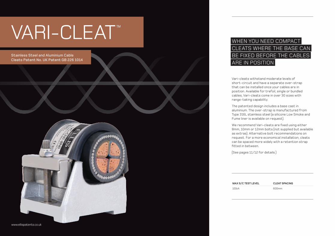
VARI-CLEAT™
Stainless Steel and Aluminium Cable Cleats Patent No. UK Patent GB 226 1014
www.ellispatents.co.uk
WHEN YOU NEED COMPACTCLEATS WHERE THE BASE CANBE FIXED BEFORE THE CABLESARE IN POSITION
Vari-cleats withstand moderate levels of short-circuit and have a separate over-strap that can be installed once your cables are in position. Available for trefoil, single or bundled cables, Vari-cleats come in over 30 sizes with range-taking capability.
The patented design includes a base cast in aluminium. The over-strap is manufactured from Type 316L stainless steel (a silicone Low Smoke and Fume liner is available on request).
We recommend Vari-cleats are fi xed using either 8mm, 10mm or 12mm bolts (not supplied but available as extras). Alternative bolt recommendations on request. For a more economical installation, cleats can be spaced more widely with a retention strap fi tted in between.
(See pages 11/12 for details.)
MAX S/C TEST LEVEL CLEAT SPACING
101kA 600mm
/1514www.ellispatents.co.uk
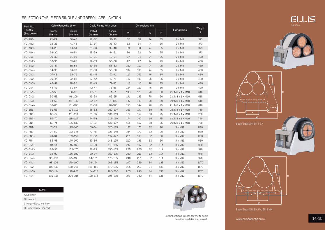
SELECTION TABLE FOR SINGLE AND TREFOIL APPLICATION
Part No. - Suffi x(See below)
Cable Range No Liner Cable Range With Liner Dimensions mm
Fixing HolesWeight
gTrefoilDia. mm
SingleDia. mm
TrefoilDia. mm
SingleDia. mm
W H D P
VC-AN1- 21-24 36-43 19-22 31-38 82 80 74 25 2 x M8 373
VC-AN2- 22-26 41-48 21-24 36-43 82 84 74 25 2 x M8 373
VC-AN3- 24-28 44-51 23-26 39-46 83 88 74 25 2 x M8 373
VC-AN4- 26-30 49-54 25-29 44-51 86 92 74 25 2 x M8 373
VC-BN1- 29-33 51-59 27-31 46-54 97 94 74 25 2 x M8 430
VC-BN2- 30-35 55-63 29-33 50-58 97 97 74 25 2 x M8 430
VC-BN3- 32-37 60-68 30-36 55-63 100 101 74 25 2 x M8 430
VC-BN4- 34-38 64-70 33-38 59-68 104 105 74 25 2 x M8 430
VC-CN1- 37-42 68-76 35-40 63-71 117 105 76 25 2 x M8 490
VC-CN2- 39-44 72-81 37-42 67-76 117 109 76 25 2 x M8 490
VC-CN3- 42-47 76-85 39-45 71-80 118 115 76 25 2 x M8 490
VC-CN4- 44-48 81-87 42-47 76-86 124 121 76 50 2 x M8 490
VC-DN1- 47-53 86-96 47-51 81-91 138 126 78 50 2 x M8 + 1 x M10 610
VC-DN2- 50-56 91-100 49-54 86-95 141 132 78 50 2 x M8 + 1 x M10 610
VC-DN3- 54-59 96-105 52-57 91-100 147 138 78 50 2 x M8 + 1 x M10 610
VC-DN4- 56-60 101-106 55-60 96-106 153 144 78 75 2 x M8 + 1 x M10 610
VC-EN1- 59-63 105-112 58-62 100-107 163 147 80 75 2 x M8 + 1 x M10 730
VC-EN2- 62-67 111-118 61-66 106-113 167 154 80 75 2 x M8 + 1 x M10 730
VC-EN3- 65-70 118-125 64-69 113-120 174 160 80 75 2 x M8 + 1 x M10 730
VC-EN4- 68-74 125-132 67-73 120-127 181 167 80 75 2 x M8 + 1 x M10 730
VC-FN1- 71-76 125-140 69-74 120-135 187 170 82 90 3 x M12 880
VC-FN2- 74-80 132-145 72-78 128-140 194 177 82 90 3 x M12 880
VC-FN3- 78-84 139-152 76-82 134-147 201 185 82 90 3 x M12 880
VC-FN4- 82-88 148-160 80-86 143-155 210 193 82 90 3 x M12 880
VC-GN1- 84-91 145-160 82-89 140-155 217 197 82 114 3 x M12 970
VC-GN2- 88-95 155-170 86-93 150-165 225 205 82 114 3 x M12 970
VC-GN3- 92-99 165-180 90-97 160-175 233 213 82 114 3 x M12 970
VC-GN4- 96-103 175-190 94-101 170-185 240 221 82 114 3 x M12 970
VC-HN1- 98-106 170-190 96-104 165-185 247 229 84 136 3 x M12 1170
VC-HN2- 102-110 180-200 100-108 175-195 255 237 84 136 3 x M12 1170
VC-HN3- 106-114 190-205 104-112 185-200 263 245 84 136 3 x M12 1170
VC-HN4- 110-118 200-215 108-116 195-210 271 252 84 136 3 x M12 1170
Special options: Cleats for multi-cable bundles available on request.
Suffi x
A No liner
B Linered
C Heavy Duty No liner
D Heavy Duty Linered
Base Sizes AN, BN & CN
Base Sizes DN, EN, FN, GN & HN

ATLAS™
Galvanized Steel Cable CleatsPatent No. UK Patent GB 228 4444
www.ellispatents.co.uk
WHEN YOU NEED CLEATS THAT WITHSTAND HIGH LEVELS OF SHORT-CIRCUIT, AND HAVEMORE FIXING OPTIONS
Atlas cable cleats are available for trefoil and single cable applications and can be fi xed using one bolt, two bolts or a framing channel fi xing. Manufactured in galvanised steel, Atlas cleats are supplied with a stainless steel top bolt to eliminate eddy currents. To protect and cushion the cables during short-circuit conditions, the cleat comes with integral Low Smoke and Fume Zero Halogen Polymeric pads. For Atlas Intermediate Strap type AS please contact our sales offi ce.
MAX S/C TEST LEVEL CLEAT SPACING
112kA 750mm

/1716www.ellispatents.co.uk
PW
H
W
H
W
H
SELECTION TABLE FOR TREFOIL CABLE APPLICATION
Part No.Cable Dia. Range mm
Dimensions mmWeight
gTwo Bolt Single Bolt Framing Channel
W H D P Fixing Holes W H D Fixing Holes W H D Fixing Holes
AR2-A31- 24-26 170 121 54 150 2 x M10 144 130 54 1 x M10 144 125 54 1 x M10 930
AR2-A32- 26-30 170 122 54 150 2 x M10 144 130 54 1 x M10 144 125 54 1 x M10 930
AR2-A33- 30-35 170 133 54 150 2 x M10 157 141 54 1 x M10 157 136 54 1 x M10 970
AR2-A34- 35-40 170 134 54 150 2 x M10 158 142 54 1 x M10 158 137 54 1 x M10 930
AR3-A35- 40-45 198 158 54 175 2 x M10 185 165 54 1 x M10 185 160 54 1 x M10 1200
AR3-A36- 45-50 198 160 54 175 2 x M10 187 167 54 1 x M10 187 162 54 1 x M10 1200
AR4-A37- 50-55 214 174 54 200 2 x M10 204 182 54 1 x M12 204 177 54 1 x M12 1300
AR4-A38- 55-60 214 179 54 200 2 x M10 210 187 54 1 x M12 210 182 54 1 x M12 1300
AR4-A39- 60-66 214 185 54 200 2 x M10 217 193 54 1 x M12 217 188 54 1 x M12 1300
AR5-A61- 66-71 250 225 54 225 2 x M10 254 225 54 1 x M12 254 220 54 1 x M12 1800
AR5-A62- 71-76 250 226 54 225 2 x M10 255 226 54 1 x M12 255 221 54 1 x M12 1800
AR5-A63- 76-82 250 230 54 225 2 x M10 260 230 54 1 x M12 260 225 54 1 x M12 1800
AR8-A64- 82-92 285 250 54 225 2 x M10 N/A N/A 2100
AR8-A65- 92-102 285 250 54 225 2 x M10 N/A N/A 1900
To order please add fi xing suffi x:Two Bolt - TB Single Bolt - SB Framing Channel - FC
SELECTION TABLE FOR SINGLE CABLE APPLICATION
Part No.Cable Dia. Range mm
Dimensions mm
Weightg
Two Bolt Single Bolt Framing Channel
W H D P Fixing Holes W H D Fixing Holes W H D Fixing Holes
AR2-A11- 38-41 170 128 54 150 2 x M10 144 136 54 1 x M10 144 131 54 1 x M10 950
AR2-A12- 41-47 170 129 54 150 2 x M10 144 136 54 1 x M10 144 131 54 1 x M10 930
AR2-A13- 47-55 170 140 54 150 2 x M10 157 147 54 1 x M10 157 142 54 1 x M10 940
AR2-A14- 55-63 170 141 54 150 2 x M10 158 148 54 1 x M10 158 143 54 1 x M10 930
AR3-A15- 63-70 198 164 54 175 2 x M10 185 172 54 1 x M10 185 167 54 1 x M10 1200
AR3-A16- 70-79 198 166 54 175 2 x M10 187 173 54 1 x M10 187 168 54 1 x M10 1200
AR4-A17- 79-87 214 180 54 200 2 x M10 204 188 54 1 x M12 204 183 54 1 x M12 1300
AR4-A18- 87-95 214 186 54 200 2 x M10 210 193 54 1 x M12 210 188 54 1 x M12 1300
AR4-A19- 95-104 214 192 54 200 2 x M10 217 199 54 1 x M12 217 197 54 1 x M12 1300
AR5-A51- 104-112 250 231 54 225 2 x M10 254 231 54 1 x M12 254 226 54 1 x M12 1700
AR5-A52- 112-120 250 232 54 225 2 x M10 255 232 54 1 x M12 255 227 54 1 x M12 1700
AR5-A53- 120-130 250 237 54 225 2 x M10 260 237 54 1 x M12 260 232 54 1 x M12 1700
H
W
H
W

MAX S/C TEST LEVEL CLEAT SPACING
104kAColossus every 7.8m with intermediate straps every 1.3m
COLOSSUS™
Hybrid Cable Cleat Community Design Application No: 001927583
WHEN YOU NEED CLEATS THAT WITHSTAND MODERATE LEVELS OF SHORT-CIRCUIT
Our Colossus cleats are a direct alternative to the all polymer (polyamide) cleats offered by some manufacturers. The unique design of Colossus combines a Low Smoke and Fume Zero Halogen polymer frame with the strength of a 316L stainless steel skeleton.
The strength of polymer cleats is typically quoted in Newtons and depending on the variant, range from 10,000N – 30,000N. On the same basis, all Colossus cleats have a strength of 63,000N irrespective of variant.
The composite structure of Colossus allows a compact design, which in turn allows for closer cable runs, in comparison to its all polymer competitors. The stainless steel element of Colossus ensures that the effects of UV radiation and “creep” (exhibited by all thermoplastic polymers) can be ignored. Colossus cleats will also retain cables (whatever the mounting orientation) in the event of a fi re.
With its depth increasing across the range, Colossus is ideally suited for cleating very large diameter cables in trefoil (up to 170mm). The saddled version of Colossus is ideal for cleating cables simply supported at large centres, typically from 3 to 8 metres.
www.ellispatents.co.uk

/1918www.ellispatents.co.uk
COLOSSUS CLEAT
Part No. Cable Range Dimensions mm Weight
gMin Dia. mm Max Dia. mm W H D P Fixing Holes
COL24-29 24 29 128 87 60 25 2 x M10 + 1 x M12 1097
COL27-32 27 32 133 92 60 25 2 x M10 + 1 x M12 1125
COL30-36 30 36 137 101 60 25 2 x M10 + 1 x M12 1146
COL34-41 34 41 146 110 60 25 2 x M10 + 1 x M12 1218
COL39-47 39 47 157 122 60 25 2 x M10 + 1 x M12 1280
COL45-54 45 54 171 141 70 50 2 x M10 1455
COL52-62 52 62 185 156 70 50 2 x M10 1568
COL60-72 60 72 204 176 70 50 2 x M10 1682
COL69-83 69 83 225 202 100 75 2 x M12 2212
COL79-95 79 95 247 225 100 75 2 x M12 2374
COL91-109 91 109 273 253 100 120 2 x M12 2588
COL105-126 105 126 306 286 150 120 2 x M12 3737
COL122-146 122 146 345 324 150 150 2 x M12 4135
COL142-170 142 170 390 371 150 150 2 x M12 4633
SADDLED COLOSSUS CLEATS
Part No. Cable Range Dimensions mm Weight
gMin Dia. mm Max Dia. mm W H D P Fixing Holes
COL69-83SC 69 83 225 202 300 75 2 x M12 2532
COL79-95SC 79 95 247 225 300 75 2 x M12 2726
COL91-109SC 91 109 273 253 300 120 2 x M12 2995
COL105-126SC 105 126 306 286 300 120 2 x M12 4108
COL122-146SC 122 146 345 324 300 150 2 x M12 4562
COL142-170SC 142 170 390 371 300 150 2 x M12 5095
P
D1W
H
D
D1
P
W
H
D
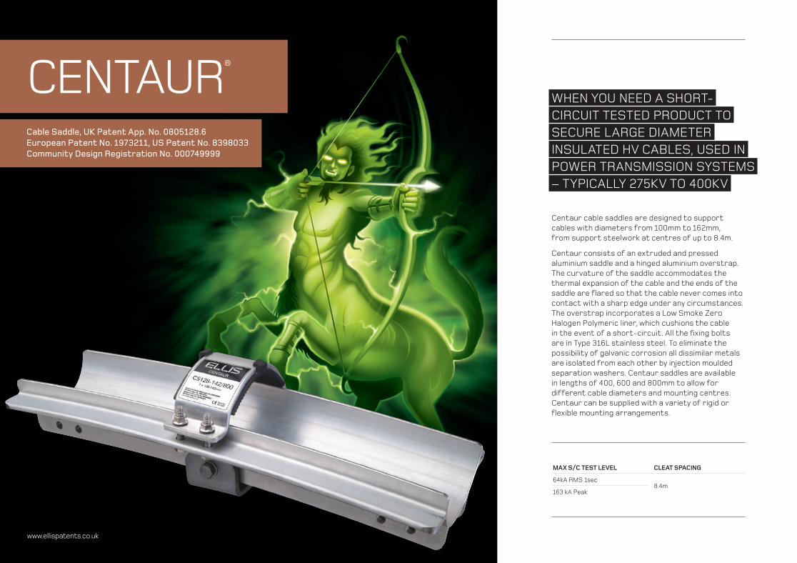
WHEN YOU NEED A SHORT-CIRCUIT TESTED PRODUCT TO SECURE LARGE DIAMETER INSULATED HV CABLES, USED IN POWER TRANSMISSION SYSTEMS – TYPICALLY 275KV TO 400KV
Centaur cable saddles are designed to support cables with diameters from 100mm to 162mm, from support steelwork at centres of up to 8.4m.
Centaur consists of an extruded and pressed aluminium saddle and a hinged aluminium overstrap. The curvature of the saddle accommodates the thermal expansion of the cable and the ends of the saddle are fl ared so that the cable never comes into contact with a sharp edge under any circumstances. The overstrap incorporates a Low Smoke Zero Halogen Polymeric liner, which cushions the cable in the event of a short-circuit. All the fi xing bolts are in Type 316L stainless steel. To eliminate the possibility of galvanic corrosion all dissimilar metals are isolated from each other by injection moulded separation washers. Centaur saddles are available in lengths of 400, 600 and 800mm to allow for different cable diameters and mounting centres. Centaur can be supplied with a variety of rigid or fl exible mounting arrangements.
Cable Saddle, UK Patent App. No. 0805128.6European Patent No. 1973211, US Patent No. 8398033Community Design Registration No. 000749999
CENTAUR®
MAX S/C TEST LEVEL CLEAT SPACING
64kA RMS 1sec8.4m
163 kA Peak
www.ellispatents.co.uk

/2120www.ellispatents.co.ukCS148-162/400 4CG8 CS148-162/800 4CG8
Part No. Cable Range Dia. mm Length of Cable Saddle
CS100-112/400 100-112
400mm
CS108-122/400 108-122
CS120-132/400 120-132
CS128-142/400 128-142
CS140-152/400 140-152
CS148-162/400 148-162
CS100-112/600 100-112
600mm
CS108-122/600 108-122
CS120-132/600 120-132
CS128-142/600 128-142
CS140-152/600 140-152
CS148-162/600 148-162
CS100-112/800 100-112
800mm
CS108-122/800 108-122
CS120-132/800 120-132
CS128-142/800 128-142
CS140-152/800 140-152
CS148-162/800 148-162
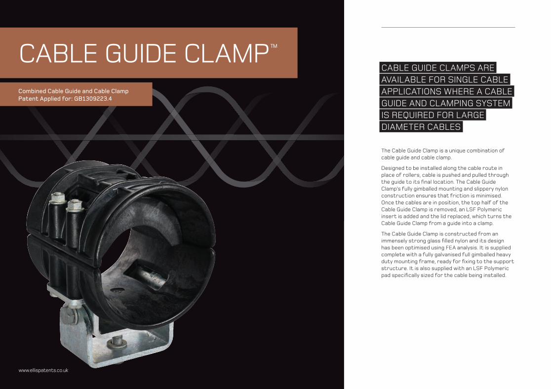
CABLE GUIDE CLAMPS AREAVAILABLE FOR SINGLE CABLEAPPLICATIONS WHERE A CABLEGUIDE AND CLAMPING SYSTEMIS REQUIRED FOR LARGE DIAMETER CABLES
The Cable Guide Clamp is a unique combination of cable guide and cable clamp.
Designed to be installed along the cable route in place of rollers, cable is pushed and pulled through the guide to its fi nal location. The Cable Guide Clamp’s fully gimballed mounting and slippery nylon construction ensures that friction is minimised. Once the cables are in position, the top half of the Cable Guide Clamp is removed, an LSF Polymeric insert is added and the lid replaced, which turns the Cable Guide Clamp from a guide into a clamp.
The Cable Guide Clamp is constructed from an immensely strong glass fi lled nylon and its design has been optimised using FEA analysis. It is supplied complete with a fully galvanised full gimballed heavy duty mounting frame, ready for fi xing to the support structure. It is also supplied with an LSF Polymeric pad specifi cally sized for the cable being installed.
CABLE GUIDE CLAMP™
Combined Cable Guide and Cable Clamp Patent Applied for: GB1309223.4
www.ellispatents.co.uk
/2322www.ellispatents.co.uk
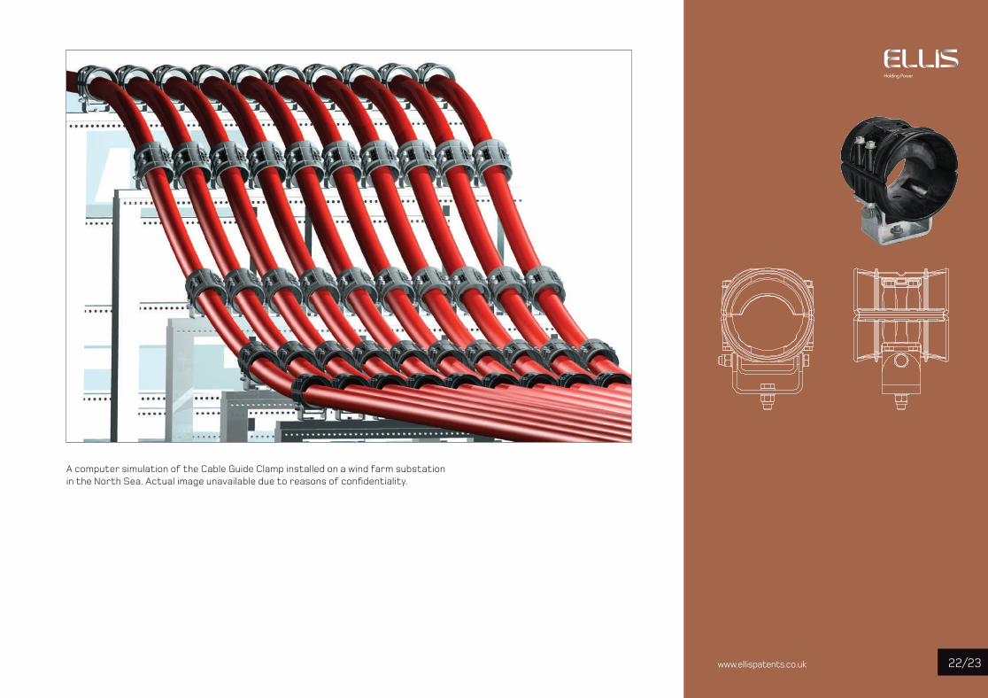
A computer simulation of the Cable Guide Clamp installed on a wind farm substation in the North Sea. Actual image unavailable due to reasons of confi dentiality.
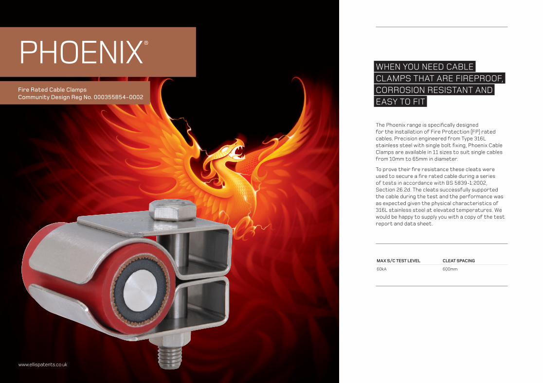
WHEN YOU NEED CABLE CLAMPS THAT ARE FIREPROOF, CORROSION RESISTANT AND EASY TO FIT
The Phoenix range is specifi cally designed for the installation of Fire Protection (FP) rated cables. Precision engineered from Type 316L stainless steel with single bolt fi xing, Phoenix Cable Clamps are available in 11 sizes to suit single cables from 10mm to 65mm in diameter.
To prove their fi re resistance these cleats were used to secure a fi re rated cable during a series of tests in accordance with BS 5839-1:2002, Section 26.2d. The cleats successfully supported the cable during the test and the performance was as expected given the physical characteristics of 316L stainless steel at elevated temperatures. We would be happy to supply you with a copy of the test report and data sheet.
MAX S/C TEST LEVEL CLEAT SPACING
60kA 600mm
Fire Rated Cable ClampsCommunity Design Reg No. 000355854-0002
PHOENIX®
www.ellispatents.co.uk
/2524www.ellispatents.co.uk
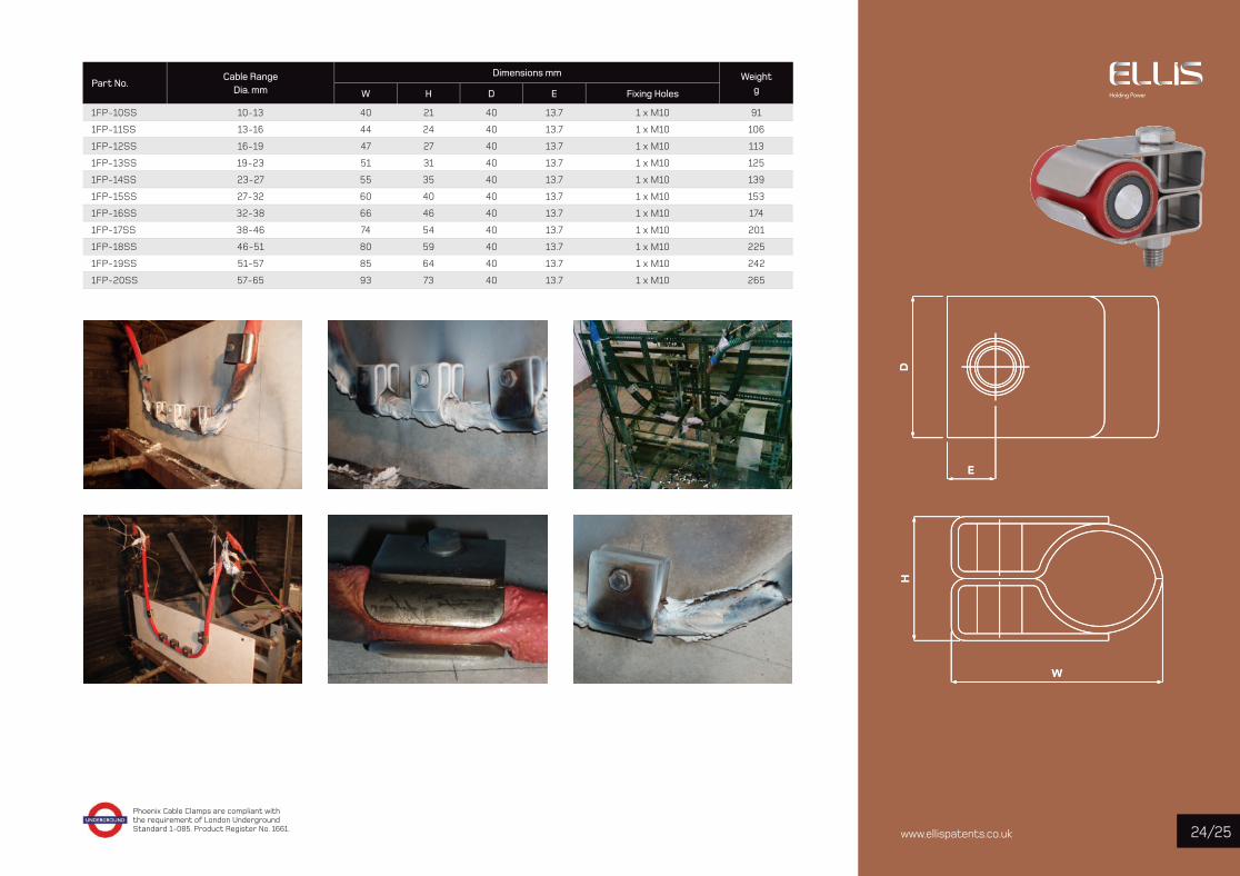
Phoenix Cable Clamps are compliant with the requirement of London Underground Standard 1-085. Product Register No. 1661.
Part No.Cable Range
Dia. mm
Dimensions mm Weight gW H D E Fixing Holes
1FP-10SS 10-13 40 21 40 13.7 1 x M10 91
1FP-11SS 13-16 44 24 40 13.7 1 x M10 106
1FP-12SS 16-19 47 27 40 13.7 1 x M10 113
1FP-13SS 19-23 51 31 40 13.7 1 x M10 125
1FP-14SS 23-27 55 35 40 13.7 1 x M10 139
1FP-15SS 27-32 60 40 40 13.7 1 x M10 153
1FP-16SS 32-38 66 46 40 13.7 1 x M10 174
1FP-17SS 38-46 74 54 40 13.7 1 x M10 201
1FP-18SS 46-51 80 59 40 13.7 1 x M10 225
1FP-19SS 51-57 85 64 40 13.7 1 x M10 242
1FP-20SS 57-65 93 73 40 13.7 1 x M10 265
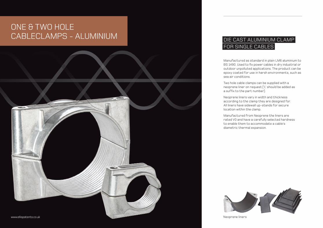
DIE CAST ALUMINIUM CLAMPFOR SINGLE CABLES
Manufactured as standard in plain LM6 aluminium to BS 1490. Used to fi x power cables in dry industrial or outdoor unpolluted applications. The product can be epoxy coated for use in harsh environments, such as sea air conditions.
Two hole cable clamps can be supplied with a neoprene liner on request (‘L’ should be added as a suffi x to the part number).
Neoprene liners vary in width and thickness according to the clamp they are designed for. All liners have sidewall up-stands for secure location within the clamp.
Manufactured from Neoprene the liners are rated V0 and have a carefully selected hardness to enable them to accommodate a cable’s diametric thermal expansion.
ONE & TWO HOLE CABLECLAMPS - ALUMINIUM
www.ellispatents.co.uk Neoprene liners
/27www.ellispatents.co.uk 26
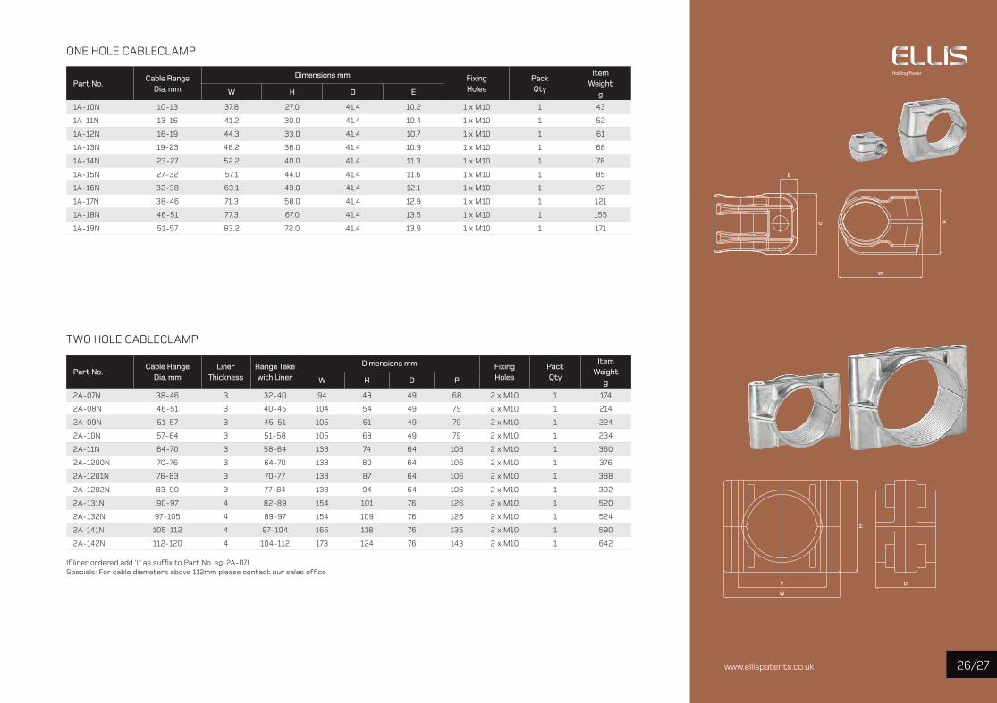
ONE HOLE CABLECLAMP
Part No. Cable Range
Dia. mm
Dimensions mm Fixing Holes
Pack Qty
Item Weight
gW H D E
1A-10N 10-13 37.8 27.0 41.4 10.2 1 x M10 1 43
1A-11N 13-16 41.2 30.0 41.4 10.4 1 x M10 1 52
1A-12N 16-19 44.3 33.0 41.4 10.7 1 x M10 1 61
1A-13N 19-23 48.2 36.0 41.4 10.9 1 x M10 1 68
1A-14N 23-27 52.2 40.0 41.4 11.3 1 x M10 1 78
1A-15N 27-32 57.1 44.0 41.4 11.6 1 x M10 1 85
1A-16N 32-38 63.1 49.0 41.4 12.1 1 x M10 1 97
1A-17N 38-46 71.3 58.0 41.4 12.9 1 x M10 1 121
1A-18N 46-51 77.3 67.0 41.4 13.5 1 x M10 1 155
1A-19N 51-57 83.2 72.0 41.4 13.9 1 x M10 1 171
TWO HOLE CABLECLAMP
Part No. Cable Range
Dia. mmLiner
ThicknessRange Take with Liner
Dimensions mm Fixing Holes
Pack Qty
Item Weight
gW H D P
2A-07N 38-46 3 32-40 94 48 49 68 2 x M10 1 174
2A-08N 46-51 3 40-45 104 54 49 79 2 x M10 1 214
2A-09N 51-57 3 45-51 105 61 49 79 2 x M10 1 224
2A-10N 57-64 3 51-58 105 68 49 79 2 x M10 1 234
2A-11N 64-70 3 58-64 133 74 64 106 2 x M10 1 360
2A-1200N 70-76 3 64-70 133 80 64 106 2 x M10 1 376
2A-1201N 76-83 3 70-77 133 87 64 106 2 x M10 1 388
2A-1202N 83-90 3 77-84 133 94 64 106 2 x M10 1 392
2A-131N 90-97 4 82-89 154 101 76 126 2 x M10 1 520
2A-132N 97-105 4 89-97 154 109 76 126 2 x M10 1 524
2A-141N 105-112 4 97-104 165 118 76 135 2 x M10 1 590
2A-142N 112-120 4 104-112 173 124 76 143 2 x M10 1 642
If liner ordered add ‘L’ as suffix to Part No. eg: 2A-07L.Specials: For cable diameters above 112mm please contact our sales office.
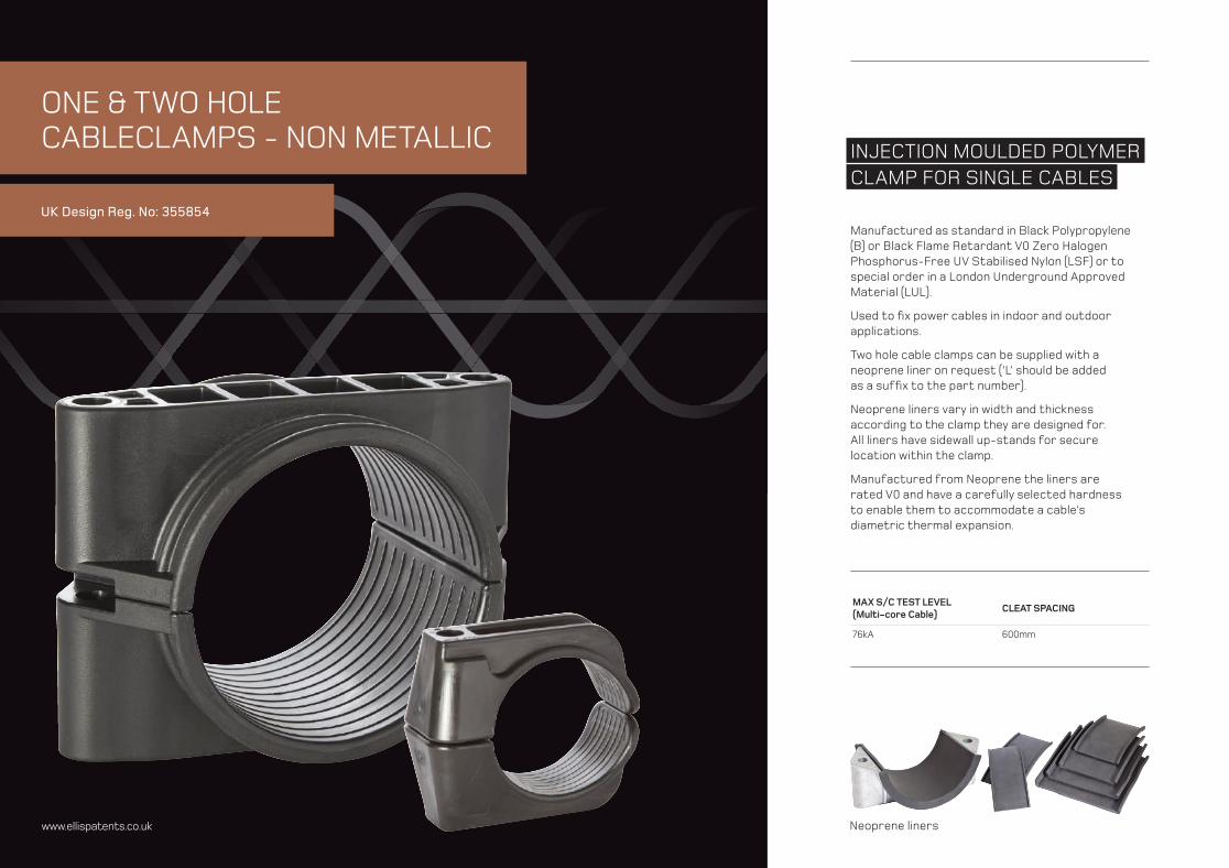
INJECTION MOULDED POLYMERCLAMP FOR SINGLE CABLES
UK Design Reg. No: 355854
www.ellispatents.co.uk
ONE & TWO HOLE CABLECLAMPS - NON METALLIC
MAX S/C TEST LEVEL(Multi-core Cable)
CLEAT SPACING
76kA 600mm
Manufactured as standard in Black Polypropylene (B) or Black Flame Retardant V0 Zero Halogen Phosphorus-Free UV Stabilised Nylon (LSF) or to special order in a London Underground Approved Material (LUL).
Used to fi x power cables in indoor and outdoor applications.
Two hole cable clamps can be supplied with a neoprene liner on request (‘L’ should be added as a suffi x to the part number).
Neoprene liners vary in width and thickness according to the clamp they are designed for. All liners have sidewall up-stands for secure location within the clamp.
Manufactured from Neoprene the liners are rated V0 and have a carefully selected hardness to enable them to accommodate a cable’s diametric thermal expansion.
Neoprene liners
/2928www.ellispatents.co.uk
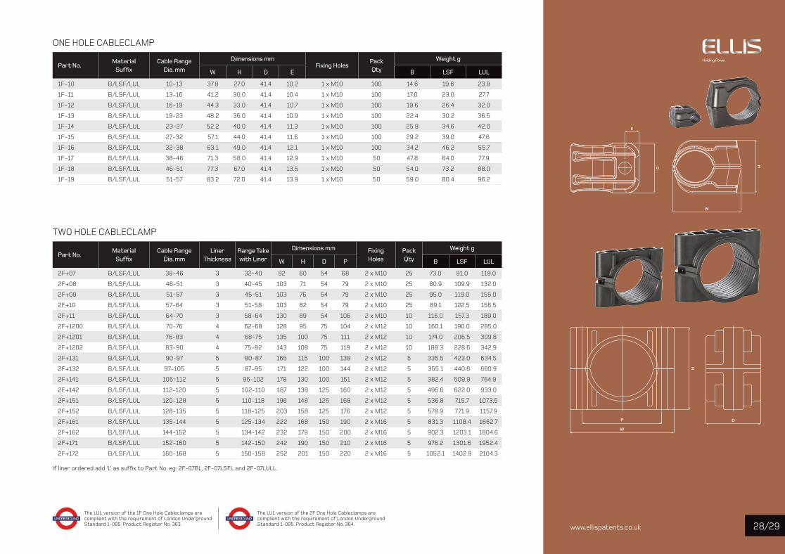
ONE HOLE CABLECLAMP
Part No. Material
Suffi x Cable Range
Dia. mm
Dimensions mmFixing Holes
Pack Qty
Weight g
W H D E B LSF LUL
1F-10 B/LSF/LUL 10-13 37.8 27.0 41.4 10.2 1 x M10 100 14.6 19.6 23.8
1F-11 B/LSF/LUL 13-16 41.2 30.0 41.4 10.4 1 x M10 100 17.0 23.0 27.7
1F-12 B/LSF/LUL 16-19 44.3 33.0 41.4 10.7 1 x M10 100 19.6 26.4 32.0
1F-13 B/LSF/LUL 19-23 48.2 36.0 41.4 10.9 1 x M10 100 22.4 30.2 36.5
1F-14 B/LSF/LUL 23-27 52.2 40.0 41.4 11.3 1 x M10 100 25.8 34.6 42.0
1F-15 B/LSF/LUL 27-32 57.1 44.0 41.4 11.6 1 x M10 100 29.2 39.0 47.6
1F-16 B/LSF/LUL 32-38 63.1 49.0 41.4 12.1 1 x M10 100 34.2 46.2 55.7
1F-17 B/LSF/LUL 38-46 71.3 58.0 41.4 12.9 1 x M10 50 47.8 64.0 77.9
1F-18 B/LSF/LUL 46-51 77.3 67.0 41.4 13.5 1 x M10 50 54.0 73.2 88.0
1F-19 B/LSF/LUL 51-57 83.2 72.0 41.4 13.9 1 x M10 50 59.0 80.4 96.2
TWO HOLE CABLECLAMP
Part No. Material
Suffi x Cable Range
Dia. mmLiner
ThicknessRange Take with Liner
Dimensions mm Fixing Holes
Pack Qty
Weight g
W H D P B LSF LUL
2F+07 B/LSF/LUL 38-46 3 32-40 92 60 54 68 2 x M10 25 73.0 91.0 119.0
2F+08 B/LSF/LUL 46-51 3 40-45 103 71 54 79 2 x M10 25 80.9 109.9 132.0
2F+09 B/LSF/LUL 51-57 3 45-51 103 76 54 79 2 x M10 25 95.0 119.0 155.0
2F+10 B/LSF/LUL 57-64 3 51-58 103 82 54 79 2 x M10 25 89.1 122.5 156.5
2F+11 B/LSF/LUL 64-70 3 58-64 130 89 54 106 2 x M10 10 116.0 157.3 189.0
2F+1200 B/LSF/LUL 70-76 4 62-68 128 95 75 104 2 x M12 10 160.1 190.0 285.0
2F+1201 B/LSF/LUL 76-83 4 68-75 135 100 75 111 2 x M12 10 174.0 206.5 309.8
2F+1202 B/LSF/LUL 83-90 4 75-82 143 108 75 119 2 x M12 10 188.3 228.6 342.9
2F+131 B/LSF/LUL 90-97 5 80-87 165 115 100 138 2 x M12 5 335.5 423.0 634.5
2F+132 B/LSF/LUL 97-105 5 87-95 171 122 100 144 2 x M12 5 355.1 440.6 660.9
2F+141 B/LSF/LUL 105-112 5 95-102 178 130 100 151 2 x M12 5 382.4 509.9 764.9
2F+142 B/LSF/LUL 112-120 5 102-110 187 138 125 160 2 x M12 5 495.6 622.0 933.0
2F+151 B/LSF/LUL 120-128 5 110-118 196 148 125 168 2 x M12 5 536.8 715.7 1073.5
2F+152 B/LSF/LUL 128-135 5 118-125 203 158 125 176 2 x M12 5 578.9 771.9 1157.9
2F+161 B/LSF/LUL 135-144 5 125-134 222 168 150 190 2 x M16 5 831.3 1108.4 1662.7
2F+162 B/LSF/LUL 144-152 5 134-142 232 179 150 200 2 x M16 5 902.3 1203.1 1804.6
2F+171 B/LSF/LUL 152-160 5 142-150 242 190 150 210 2 x M16 5 976.2 1301.6 1952.4
2F+172 B/LSF/LUL 160-168 5 150-158 252 201 150 220 2 x M16 5 1052.1 1402.9 2104.3
If liner ordered add ‘L’ as suffi x to Part No. eg: 2F-07BL, 2F-07LSFL and 2F-07LULL.
The LUL version of the 1F One Hole Cableclamps are compliant with the requirement of London Underground Standard 1-085. Product Register No. 363.
The LUL version of the 2F One Hole Cableclamps are compliant with the requirement of London Underground Standard 1-085. Product Register No. 364.
ww
w.e
llispa
tent
s.co
.uk
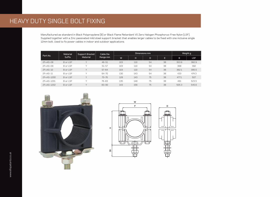
HEAVY DUTY SINGLE BOLT FIXING
Manufactured as standard in Black Polypropylene (B) or Black Flame Retardant V0 Zero Halogen Phosphorus-Free Nylon (LSF). Supplied together with a Zinc passivated mild steel support bracket that enables larger cables to be fi xed with one inclusive single 12mm bolt. Used to fi x power cables in indoor and outdoor applications.
Part No. Material
Suffi x Support Bracket
MaterialCable Dia
Range mm
Dimensions mm Weight g
W H D E B LSF
2F+AS-08 B or LSF Y 46-51 103 110 54 38 353.9 382.9
2F+AS-09 B or LSF Y 51-57 103 110 54 38 368 392
2F+AS-10 B or LSF Y 57-64 103 110 54 38 362.1 395.5
2F+AS-11 B or LSF Y 64-70 130 143 54 38 433 474.3
2F+AS-1200 B or LSF Y 70-76 128 143 75 38 477.1 507
2F+AS-1201 B or LSF Y 76-83 135 148 75 38 491 523.5
2F+AS-1202 B or LSF Y 83-90 143 156 75 38 505.3 545.6
ww
w.e
llispa
tent
s.co
.uk
/3130
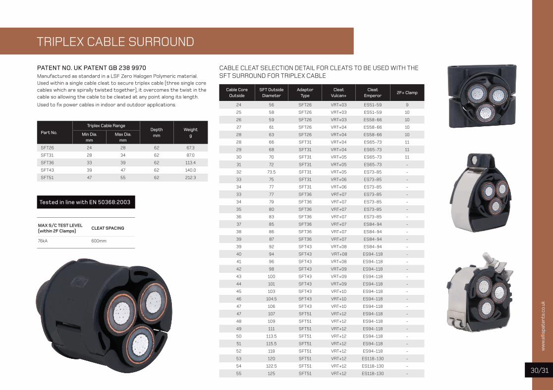
TRIPLEX CABLE SURROUND
PATENT NO. UK PATENT GB 238 9970Manufactured as standard in a LSF Zero Halogen Polymeric material. Used within a single cable cleat to secure triplex cable (three single core cables which are spirally twisted together), it overcomes the twist in the cable so allowing the cable to be cleated at any point along its length.
Used to fi x power cables in indoor and outdoor applications.
Part No.
Triplex Cable RangeDepth
mmWeight
gMin Dia. mm
Max Dia. mm
SFT26 24 28 62 67.3
SFT31 28 34 62 87.0
SFT36 33 39 62 113.4
SFT43 39 47 62 140.0
SFT51 47 55 62 212.3
CABLE CLEAT SELECTION DETAIL FOR CLEATS TO BE USED WITH THESFT SURROUND FOR TRIPLEX CABLE
Cable CoreOutside
SFT OutsideDiameter
AdaptorType
CleatVulcan+
CleatEmperor
2F+ Clamp
24 56 SFT26 VRT+03 ES51-59 9
25 58 SFT26 VRT+03 ES51-59 10
26 59 SFT26 VRT+03 ES58-66 10
27 61 SFT26 VRT+04 ES58-66 10
28 63 SFT26 VRT+04 ES58-66 10
28 66 SFT31 VRT+04 ES65-73 11
29 68 SFT31 VRT+04 ES65-73 11
30 70 SFT31 VRT+05 ES65-73 11
31 72 SFT31 VRT+05 ES65-73 -
32 73.5 SFT31 VRT+05 ES73-85 -
33 75 SFT31 VRT+06 ES73-85 -
34 77 SFT31 VRT+06 ES73-85 -
33 77 SFT36 VRT+07 ES73-85 -
34 79 SFT36 VRT+07 ES73-85 -
35 80 SFT36 VRT+07 ES73-85 -
36 83 SFT36 VRT+07 ES73-85 -
37 85 SFT36 VRT+07 ES84-94 -
38 86 SFT36 VRT+07 ES84-94 -
39 87 SFT36 VRT+07 ES84-94 -
39 92 SFT43 VRT+08 ES84-94 -
40 94 SFT43 VRT+08 ES94-118 -
41 96 SFT43 VRT+08 ES94-118 -
42 98 SFT43 VRT+09 ES94-118 -
43 100 SFT43 VRT+09 ES94-118 -
44 101 SFT43 VRT+09 ES94-118 -
45 103 SFT43 VRT+10 ES94-118 -
46 104.5 SFT43 VRT+10 ES94-118 -
47 106 SFT43 VRT+10 ES94-118 -
47 107 SFT51 VRT+12 ES94-118 -
48 109 SFT51 VRT+12 ES94-118 -
49 111 SFT51 VRT+12 ES94-118 -
50 113.5 SFT51 VRT+12 ES94-118 -
51 115.5 SFT51 VRT+12 ES94-118 -
52 118 SFT51 VRT+12 ES94-118 -
53 120 SFT51 VRT+12 ES118-130 -
54 122.5 SFT51 VRT+12 ES118-130 -
55 125 SFT51 VRT+12 ES118-130 -
MAX S/C TEST LEVEL (within 2F Clamps)
CLEAT SPACING
76kA 600mm
Tested in line with EN 50368:2003
ww
w.e
llispa
tent
s.co
.uk
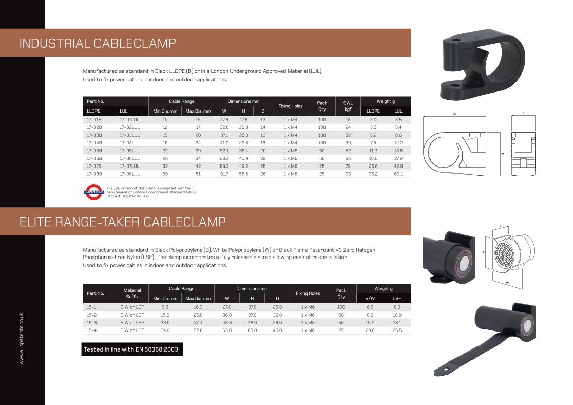
INDUSTRIAL CABLECLAMP
ELITE RANGE-TAKER CABLECLAMP
Manufactured as standard in Black LLDPE (B) or in a London Underground Approved Material (LUL).
Used to fi x power cables in indoor and outdoor applications.
Manufactured as standard in Black Polypropylene (B), White Polypropylene (W) or Black Flame Retardant V0 Zero Halogen Phosphorus-Free Nylon (LSF). The clamp incorporates a fully releasable strap allowing ease of re-installation.
Used to fi x power cables in indoor and outdoor applications.
Part No. Cable Range Dimensions mmFixing Holes
Pack Qty
SWLkgf
Weight g
LLDPE LUL Min Dia. mm Max Dia. mm W H D LLDPE LUL
17-01B 17-01LUL 10 15 27.8 17.6 12 1 x M4 100 18 2.0 3.5
17-02B 17-02LUL 12 17 32.0 20.8 14 1 x M4 100 24 3.3 5.4
17-03B 17-03LUL 15 20 37.1 25.3 16 1 x M4 100 32 5.2 8.6
17-04B 17-04LUL 18 24 41.0 29.6 18 1 x M4 100 39 7.3 12.2
17-05B 17-05LUL 22 29 52.1 35.4 20 1 x M6 50 52 11.2 18.6
17-06B 17-06LUL 26 34 58.2 40.9 22 1 x M6 50 66 16.5 27.9
17-07B 17-07LUL 32 42 69.3 49.2 25 1 x M6 25 79 25.6 42.9
17-08B 17-08LUL 39 51 81.7 58.5 26 1 x M6 25 93 36.2 60.1
Part No. Material
Suffi x
Cable Range Dimensions mmFixing Holes
Pack Qty
Weight g
Min Dia. mm Max Dia. mm W H D B/W LSF
15-1 B,W or LSF 9.5 16.0 27.0 37.0 25.0 1 x M6 100 6.0 8.0
15-2 B,W or LSF 15.0 25.0 36.0 37.0 32.0 1 x M6 50 8.0 10.9
15-3 B,W or LSF 23.0 37.0 48.0 48.0 36.0 1 x M6 50 15.0 18.1
15-4 B,W or LSF 34.0 52.0 63.0 65.0 40.0 1 x M6 25 20.0 25.5
Tested in line with EN 50368:2003
The LUL version of this clamp is compliant with the requirement of London Underground Standard 1-085. Product Register No. 365.

ww
w.e
llispa
tent
s.co
.uk
/3332
EARTHING STRIP CLIP
Manufactured as standard in Black Polypropylene (B) or Grey Flame Retardant Polypropylene (FR).
Used to fi x PVC coated, bare copper or aluminium strip.
METRIC SIZES
Part No. Material
Suffi x Strip Size
mmHold Off
mmLength
mmFixing Holes (slotted) mm
PackQty
Weightg
70-04 B or FR 20 x 4 17 55 11 x 8 100 15
70-06 B or FR 20 x 6 16 55 11 x 8 100 16
70-07 B or FR 25 x 6 16 55 11 x 8 100 14
70-08 B or FR 50 x 4 18 87 11 x 8 100 28
70-09 B or FR 40 x 6 16 87 11 x 8 100 28
70-10 B or FR 50 x 6 15 87 11 x 8 100 26
70-11 B or FR 40 x 4 18 87 11 x 8 100 28
70-12 B or FR 50 x 10 11 87 11 x 8 100 24
70-14 B or FR 60 x 6 18 97 11 x 8 100 31
70-16 B or FR 80 x 6 19 118 11 x 8 50 41
IMPERIAL SIZES
Part No. Material
Suffi x Strip Size
inchesHold Offinches
Lengthinches
Fixing Holes (slotted)
inches
PackQty
Weightg
60-04 B or FR 1 x 1⁄8 5⁄16 2 7⁄16 x 5⁄16 100 12
60-05 B or FR 1 1⁄4 x 1⁄8 3⁄8 2 5⁄8 7⁄16 x 5⁄16 100 21
60-06 B or FR 1 1⁄4 x 3⁄165⁄16 2 5⁄8 7⁄16 x 5⁄16 100 20
60-08 B or FR 1 1⁄2 x 3⁄165⁄16 2 5⁄8 7⁄16 x 5⁄16 100 20
60-10 B or FR 1 1⁄2 x 1⁄8 3⁄8 2 5⁄8 7⁄16 x 5⁄16 100 20
60-15 B or FR 2 x 1⁄8 1⁄4 3 1⁄8 7⁄16 x 5⁄16 100 24
60-26 B or FR 1 x 1⁄8 3⁄4 2 1⁄8 7⁄16 x 5⁄16 100 16
60-27 B or FR 1 x 3⁄165⁄8 2 1⁄8 7⁄16 x 5⁄16 100 16
60-28 B or FR 1 1⁄2 x 3⁄165⁄8 2 7⁄8 7⁄16 x 5⁄16 100 25
60-32 B or FR 1 1⁄4 x 1⁄4 5⁄8 3 7⁄16 x 5⁄16 100 25
60-34 B or FR 1 1⁄2 x 1⁄8 3⁄4 3 7⁄16 x 5⁄16 100 25
60-36 B or FR 1 1⁄2 x 1⁄4 5⁄8 3 7⁄16 x 5⁄16 100 24
60-37 B or FR 1 1⁄2 x 3⁄8 3⁄8 2 7⁄8 7⁄16 x 5⁄16 100 23
60-38 B or FR 1 3⁄4 x 1⁄8 3⁄4 3 3⁄8 7⁄16 x 5⁄16 100 27
60-39 B or FR 1 3⁄4 x 1⁄4 5⁄8 3 3⁄8 7⁄16 x 5⁄16 100 27
60-40 B or FR 2 x 1⁄8 3⁄4 3 3⁄8 7⁄16 x 5⁄16 100 30
60-42 B or FR 2 x 1⁄4 5⁄8 3 3⁄8 7⁄16 x 5⁄16 100 25
60-44 B or FR 2 x 3⁄8 3⁄8 3 3⁄8 7⁄16 x 5⁄16 100 24
CABLE CONDUIT CLIP
Manufactured as standard in Black or White Nylon, this surface mounted Conduit Clip comes complete with a captive hinged over-strap.
Used to fi x conduit in indoor or outdoor applications.
Part No. MaterialSuffi x
Dmm
Hmm
Wmm
Fixing Holes mm
Stand off
PackQty
Weightg
CC20B B or W 20 35 35 4 5 100 8.8
CC25B B or W 25 40 40 4 5 100 10.6
ww
w.e
llispa
tent
s.co
.uk
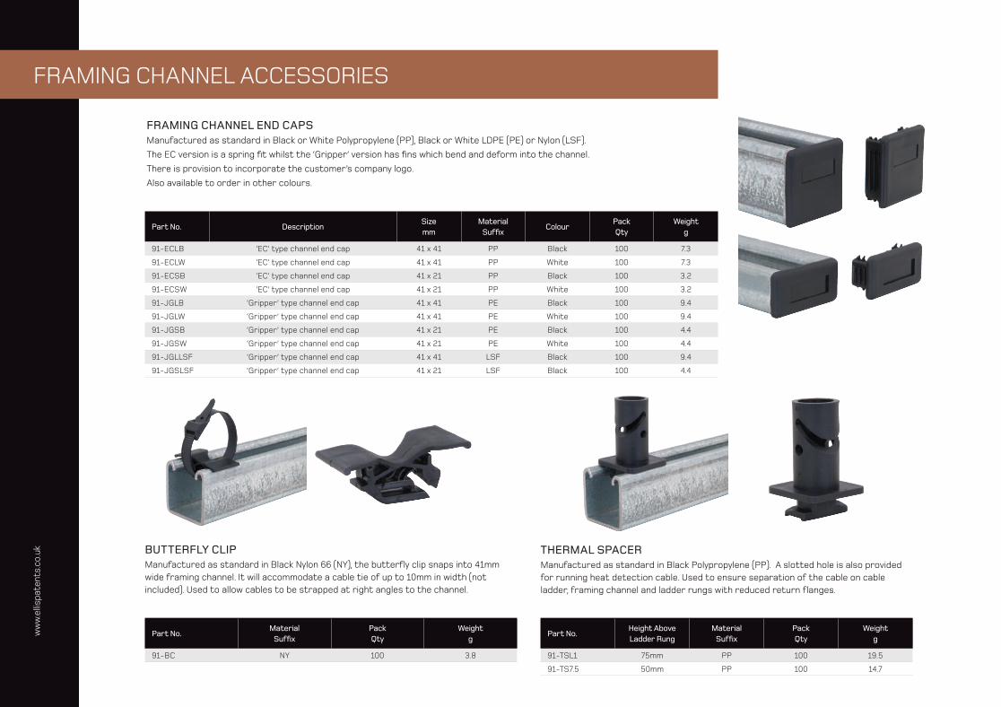
FRAMING CHANNEL ACCESSORIES
Part No. DescriptionSizemm
MaterialSuffi x
ColourPackQty
Weightg
91-ECLB ‘EC’ type channel end cap 41 x 41 PP Black 100 7.3
91-ECLW ‘EC’ type channel end cap 41 x 41 PP White 100 7.3
91-ECSB ‘EC’ type channel end cap 41 x 21 PP Black 100 3.2
91-ECSW ‘EC’ type channel end cap 41 x 21 PP White 100 3.2
91-JGLB ‘Gripper’ type channel end cap 41 x 41 PE Black 100 9.4
91-JGLW ‘Gripper’ type channel end cap 41 x 41 PE White 100 9.4
91-JGSB ‘Gripper’ type channel end cap 41 x 21 PE Black 100 4.4
91-JGSW ‘Gripper’ type channel end cap 41 x 21 PE White 100 4.4
91-JGLLSF ‘Gripper’ type channel end cap 41 x 41 LSF Black 100 9.4
91-JGSLSF ‘Gripper’ type channel end cap 41 x 21 LSF Black 100 4.4
Part No.Material
Suffi xPack Qty
Weightg
91-BC NY 100 3.8
FRAMING CHANNEL END CAPSManufactured as standard in Black or White Polypropylene (PP), Black or White LDPE (PE) or Nylon (LSF).
The EC version is a spring fi t whilst the ‘Gripper’ version has fi ns which bend and deform into the channel.
There is provision to incorporate the customer’s company logo.
Also available to order in other colours.
BUTTERFLY CLIPManufactured as standard in Black Nylon 66 (NY), the butterfl y clip snaps into 41mm wide framing channel. It will accommodate a cable tie of up to 10mm in width (not included). Used to allow cables to be strapped at right angles to the channel.
Part No.Height Above Ladder Rung
MaterialSuffi x
Pack Qty
Weightg
91-TSL1 75mm PP 100 19.5
91-TS7.5 50mm PP 100 14.7
THERMAL SPACERManufactured as standard in Black Polypropylene (PP). A slotted hole is also provided for running heat detection cable. Used to ensure separation of the cable on cable ladder, framing channel and ladder rungs with reduced return fl anges.

ww
w.e
llispa
tent
s.co
.uk
/3534
FRAMING CHANNEL WASHERManufactured as standard in the materials shown this washer is recommended for use when our range of 2H clamps are fi tted to framing channel.
TRUNKING ADAPTORManufactured as standard in Black Polypropylene (B) or Nylon (LSF), this adaptor can be used to fi t one hole and two hole cable clamps when cables are being installed parallel to the trunking.
INSULATION PLATEManufactured as standard in Black Polypropylene, this insulation plate can be used to provide a barrier where galvanic reaction may occur between dissimilar metals, e.g. when installing stainless steel cleats onto galvanised steel channel.
CHANNEL NUTSManufactured as standard in Bright Zinc Plated Mild Steel.
Part No. Size Material Suffi xHole Size
mmPackQty
Weight g
91-WZ 40 x 40 Mild Steel Zinc Plated 10 100 33
91-WZ-X 40 x 40 Mild Steel Zinc Plated 12 100 33
91-W-2 40 x 40 A2 Stainless Steel 10 100 34
91-W-4 40 x 40 A4 Stainless Steel 12 100 34
91-WG 40 x 40 Mild Steel Galvanised 10 100 37
Part No. Material Suffi x Pack Qty Weight g
91-TA B 100 5.3
91-TA LSF 100 7.1
Part No. Material Suffi x Pack Qty Weight g
91-IP B 100 5
Part No. Material Suffi x Pack Qty Weight g
0F-M10-CN00-Z M10 Channel Nut (long spring) 100 38
0F-M10-CN01-Z M10 Channel Nut (short spring) 100 37
0F-M10-CN02-Z M10 Channel Nut (no spring) 100 36
ww
w.e
llispa
tent
s.co
.uk
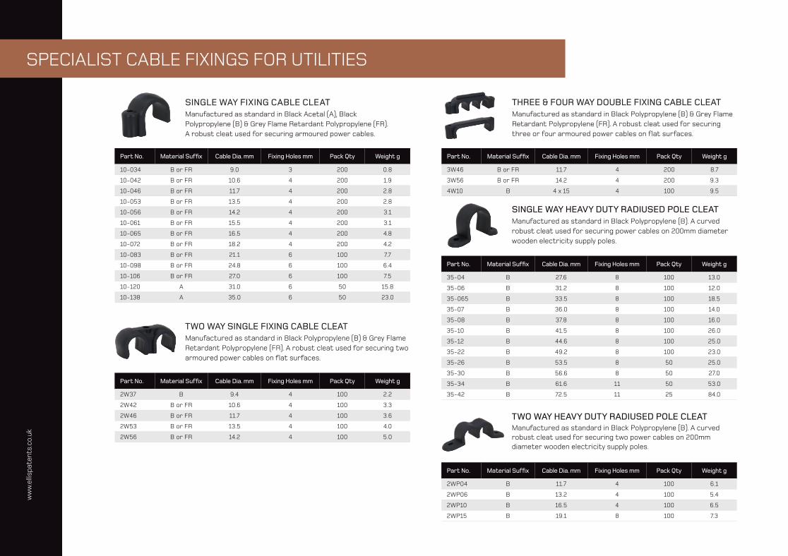
SPECIALIST CABLE FIXINGS FOR UTILITIES
THREE & FOUR WAY DOUBLE FIXING CABLE CLEATManufactured as standard in Black Polypropylene (B) & Grey Flame Retardant Polypropylene (FR). A robust cleat used for securing three or four armoured power cables on fl at surfaces.
SINGLE WAY FIXING CABLE CLEATManufactured as standard in Black Acetal (A), Black Polypropylene (B) & Grey Flame Retardant Polypropylene (FR).A robust cleat used for securing armoured power cables.
Part No. Material Suffi x Cable Dia. mm Fixing Holes mm Pack Qty Weight g
10-034 B or FR 9.0 3 200 0.8
10-042 B or FR 10.6 4 200 1.9
10-046 B or FR 11.7 4 200 2.8
10-053 B or FR 13.5 4 200 2.8
10-056 B or FR 14.2 4 200 3.1
10-061 B or FR 15.5 4 200 3.1
10-065 B or FR 16.5 4 200 4.8
10-072 B or FR 18.2 4 200 4.2
10-083 B or FR 21.1 6 100 7.7
10-098 B or FR 24.8 6 100 6.4
10-106 B or FR 27.0 6 100 7.5
10-120 A 31.0 6 50 15.8
10-138 A 35.0 6 50 23.0
TWO WAY SINGLE FIXING CABLE CLEATManufactured as standard in Black Polypropylene (B) & Grey Flame Retardant Polypropylene (FR). A robust cleat used for securing two armoured power cables on fl at surfaces.
Part No. Material Suffi x Cable Dia. mm Fixing Holes mm Pack Qty Weight g
2W37 B 9.4 4 100 2.2
2W42 B or FR 10.6 4 100 3.3
2W46 B or FR 11.7 4 100 3.6
2W53 B or FR 13.5 4 100 4.0
2W56 B or FR 14.2 4 100 5.0
Part No. Material Suffi x Cable Dia. mm Fixing Holes mm Pack Qty Weight g
3W46 B or FR 11.7 4 200 8.7
3W56 B or FR 14.2 4 200 9.3
4W10 B 4 x 15 4 100 9.5
SINGLE WAY HEAVY DUTY RADIUSED POLE CLEATManufactured as standard in Black Polypropylene (B). A curved robust cleat used for securing power cables on 200mm diameter wooden electricity supply poles.
Part No. Material Suffi x Cable Dia. mm Fixing Holes mm Pack Qty Weight g
35-04 B 27.6 8 100 13.0
35-06 B 31.2 8 100 12.0
35-065 B 33.5 8 100 18.5
35-07 B 36.0 8 100 14.0
35-08 B 37.8 8 100 16.0
35-10 B 41.5 8 100 26.0
35-12 B 44.6 8 100 25.0
35-22 B 49.2 8 100 23.0
35-26 B 53.5 8 50 25.0
35-30 B 56.6 8 50 27.0
35-34 B 61.6 11 50 53.0
35-42 B 72.5 11 25 84.0
TWO WAY HEAVY DUTY RADIUSED POLE CLEATManufactured as standard in Black Polypropylene (B). A curved robust cleat used for securing two power cables on 200mm diameter wooden electricity supply poles.
Part No. Material Suffi x Cable Dia. mm Fixing Holes mm Pack Qty Weight g
2WP04 B 11.7 4 100 6.1
2WP06 B 13.2 4 100 5.4
2WP10 B 16.5 4 100 6.5
2WP15 B 19.1 8 100 7.3
ww
w.e
llispa
tent
s.co
.uk
/3736
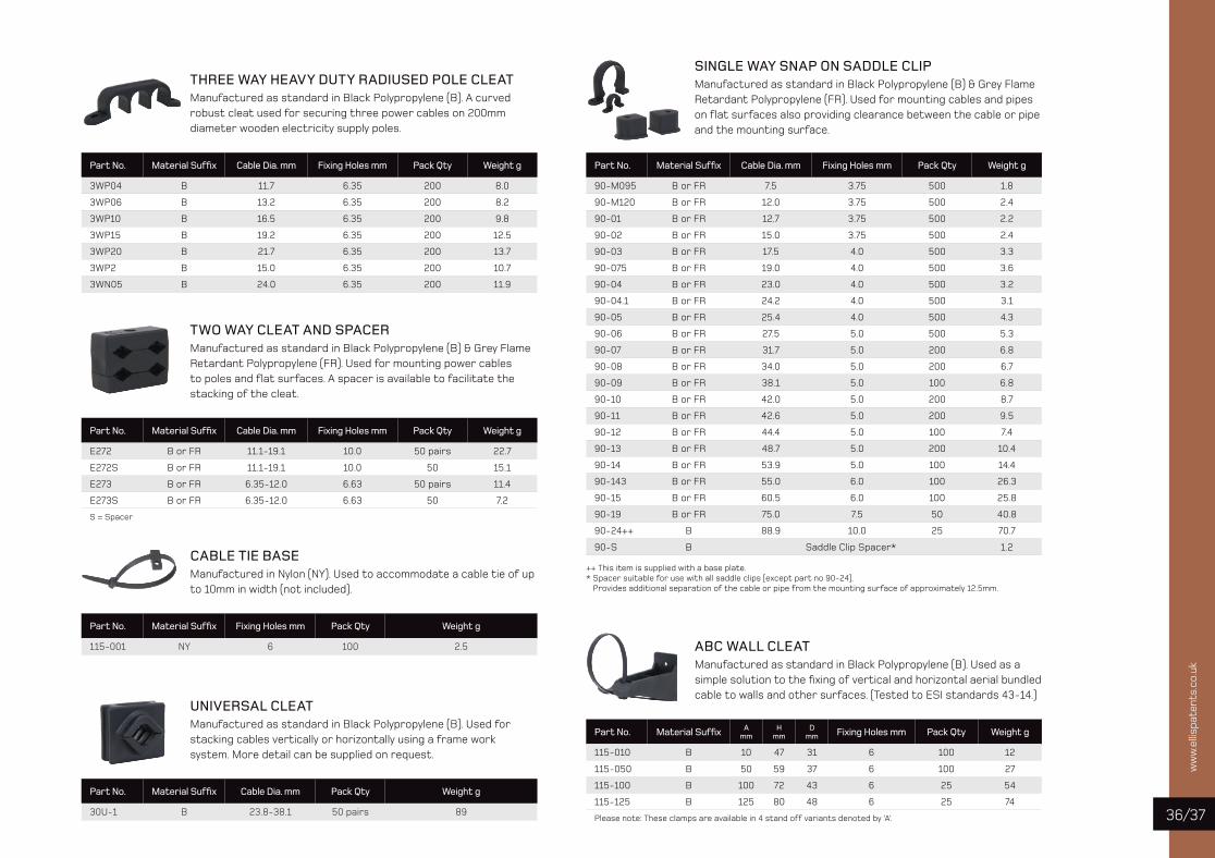
SINGLE WAY SNAP ON SADDLE CLIPManufactured as standard in Black Polypropylene (B) & Grey Flame Retardant Polypropylene (FR). Used for mounting cables and pipeson fl at surfaces also providing clearance between the cable or pipe and the mounting surface.
THREE WAY HEAVY DUTY RADIUSED POLE CLEATManufactured as standard in Black Polypropylene (B). A curved robust cleat used for securing three power cables on 200mm diameter wooden electricity supply poles.
Part No. Material Suffi x Cable Dia. mm Fixing Holes mm Pack Qty Weight g
3WP04 B 11.7 6.35 200 8.0
3WP06 B 13.2 6.35 200 8.2
3WP10 B 16.5 6.35 200 9.8
3WP15 B 19.2 6.35 200 12.5
3WP20 B 21.7 6.35 200 13.7
3WP2 B 15.0 6.35 200 10.7
3WN05 B 24.0 6.35 200 11.9
TWO WAY CLEAT AND SPACERManufactured as standard in Black Polypropylene (B) & Grey Flame Retardant Polypropylene (FR). Used for mounting power cables to poles and fl at surfaces. A spacer is available to facilitate the stacking of the cleat.
Part No. Material Suffi x Cable Dia. mm Fixing Holes mm Pack Qty Weight g
E272 B or FR 11.1-19.1 10.0 50 pairs 22.7
E272S B or FR 11.1-19.1 10.0 50 15.1
E273 B or FR 6.35-12.0 6.63 50 pairs 11.4
E273S B or FR 6.35-12.0 6.63 50 7.2
S = Spacer
CABLE TIE BASEManufactured in Nylon (NY). Used to accommodate a cable tie of up to 10mm in width (not included).
Part No. Material Suffi x Fixing Holes mm Pack Qty Weight g
115-001 NY 6 100 2.5
UNIVERSAL CLEATManufactured as standard in Black Polypropylene (B). Used for stacking cables vertically or horizontally using a frame work system. More detail can be supplied on request.
Part No. Material Suffi x Cable Dia. mm Pack Qty Weight g
30U-1 B 23.8-38.1 50 pairs 89
Part No. Material Suffi x Cable Dia. mm Fixing Holes mm Pack Qty Weight g
90-M095 B or FR 7.5 3.75 500 1.8
90-M120 B or FR 12.0 3.75 500 2.4
90-01 B or FR 12.7 3.75 500 2.2
90-02 B or FR 15.0 3.75 500 2.4
90-03 B or FR 17.5 4.0 500 3.3
90-075 B or FR 19.0 4.0 500 3.6
90-04 B or FR 23.0 4.0 500 3.2
90-04.1 B or FR 24.2 4.0 500 3.1
90-05 B or FR 25.4 4.0 500 4.3
90-06 B or FR 27.5 5.0 500 5.3
90-07 B or FR 31.7 5.0 200 6.8
90-08 B or FR 34.0 5.0 200 6.7
90-09 B or FR 38.1 5.0 100 6.8
90-10 B or FR 42.0 5.0 200 8.7
90-11 B or FR 42.6 5.0 200 9.5
90-12 B or FR 44.4 5.0 100 7.4
90-13 B or FR 48.7 5.0 200 10.4
90-14 B or FR 53.9 5.0 100 14.4
90-143 B or FR 55.0 6.0 100 26.3
90-15 B or FR 60.5 6.0 100 25.8
90-19 B or FR 75.0 7.5 50 40.8
90-24++ B 88.9 10.0 25 70.7
90-S B Saddle Clip Spacer* 1.2
++ This item is supplied with a base plate.* Spacer suitable for use with all saddle clips (except part no 90-24).
Provides additional separation of the cable or pipe from the mounting surface of approximately 12.5mm.
ABC WALL CLEATManufactured as standard in Black Polypropylene (B). Used as a simple solution to the fi xing of vertical and horizontal aerial bundled cable to walls and other surfaces. (Tested to ESI standards 43-14.)
Part No. Material Suffi x Amm
Hmm
Dmm Fixing Holes mm Pack Qty Weight g
115-010 B 10 47 31 6 100 12
115-050 B 50 59 37 6 100 27
115-100 B 100 72 43 6 25 54
115-125 B 125 80 48 6 25 74
Please note: These clamps are available in 4 stand off variants denoted by ‘A’.

ww
w.e
llispa
tent
s.co
.uk
JOINTERS’ TOOLS
CABLE CORE TWISTERSManufactured in Acetal (International Orange). Used to manipulate bare or insulated cable cores and to align the cores prior to jointing.
CABLE CORE FORMERManufactured in Nylon. Used to hold the cores of a three core cable apart whilst a joint is being made. The central hole provides a facility for positioning a mastic bung.
3 CORE
Part No. Cores Core Range Size mm2 Pack Qty Weight g
110-95C 3 70 Bare x 95 Bare 10 54
110-X01C 3 95 Bare x 95 Ins 10 51
110-120C 3 70 Bare x 120 Bare 10 51
110-120IC 3 70 Ins x 120 Ins 10 49
110-X06C 3 120 Bare x 120 Ins 10 48
110-X07C 3 185 Bare x 185 Ins 10 148
110-240C 3 185 Bare x 240 Bare 10 146
110-300C 3 185 Bare x 300 Bare 10 147
110-300IC 3 185 Ins x 300 Ins 10 139
110-X08C 3 300 Bare x 300 Ins 10 138
110-X09C 3 70 Bare x 70 Ins 10 53
110-X10C 3 95 Bare x 185 Bare 10 154
110-X11C 3 95 Ins x 185 Ins 10 149
4 CORE
Part No. Cores Core Range Size mm2 Pack Qty Weight g
110-41C 4 95 Bare x 95 Ins 10 51
110-42C 4 185 Ins x 240 Ins 10 142
110-43C 4 185 Bare x 240 Bare 10 150
110-44C 4 185 Ins x 300 Ins 10 141
110-48C 4 120 Ins x 185 Ins 10 150
110-X02C 4 185 Bare x 300 Bare 10 146
110-X14C 4 95 Bare x 185 Bare 10 155
110-X15C 4 95 Ins x 185 Ins 10 149
110-16C 4 95 Ins stranded x 95 Ins solid 10 51
110-17C 4 300 Ins stranded x 300 Ins solid 10 140
3 & 4 CORE
Part No. Cores Core Range Size mm2 Pack Qty Weight g
110-X03C 3 & 4 3C 95 Ins x 4C 95 Ins 10 50
110-X04C 3 & 4 3C 185 Ins x 4C 185 Ins 10 145
110-X05C 3 & 4 3C 300 Ins x 4C 240 Ins 10 135
110-X12C 3 & 4 3C 300 Bare x 4C 300 Bare 10 141
110-X13C 3 & 4 3C 300 Ins x 4C 300 Ins 10 134
Part No.Core Separation
Distance mmPack Qty Weight g
120-F 32 - 58 10 44.1
Complies with the Dielectric testing of IEC 60900-1
ww
w.e
llispa
tent
s.co
.uk
/3938
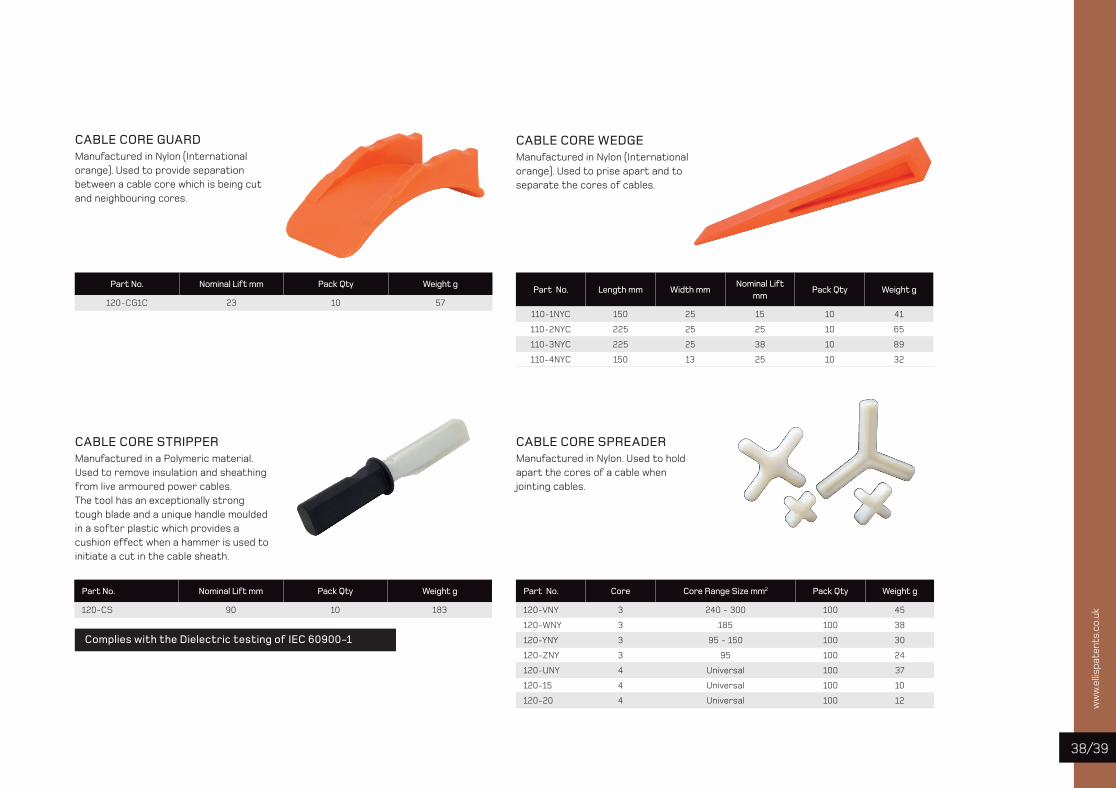
CABLE CORE STRIPPERManufactured in a Polymeric material. Used to remove insulation and sheathing from live armoured power cables. The tool has an exceptionally strong tough blade and a unique handle moulded in a softer plastic which provides a cushion effect when a hammer is used to initiate a cut in the cable sheath.
CABLE CORE SPREADERManufactured in Nylon. Used to hold apart the cores of a cable when jointing cables.
CABLE CORE GUARDManufactured in Nylon (International orange). Used to provide separation between a cable core which is being cut and neighbouring cores.
CABLE CORE WEDGEManufactured in Nylon (International orange). Used to prise apart and to separate the cores of cables.
Part No. Nominal Lift mm Pack Qty Weight g
120-CG1C 23 10 57
Part No. Nominal Lift mm Pack Qty Weight g
120-CS 90 10 183
Part No. Length mm Width mmNominal Lift
mmPack Qty Weight g
110-1NYC 150 25 15 10 41
110-2NYC 225 25 25 10 65
110-3NYC 225 25 38 10 89
110-4NYC 150 13 25 10 32
Part No. Core Core Range Size mm2 Pack Qty Weight g
120-VNY 3 240 - 300 100 45
120-WNY 3 185 100 38
120-YNY 3 95 - 150 100 30
120-ZNY 3 95 100 24
120-UNY 4 Universal 100 37
120-15 4 Universal 100 10
120-20 4 Universal 100 12
Complies with the Dielectric testing of IEC 60900-1
ww
w.e
llispa
tent
s.co
.uk
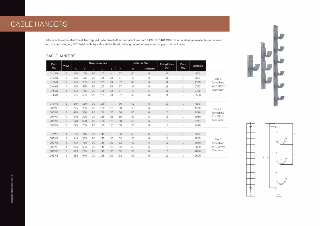
CABLE HANGERS
Manufactured in Mild Steel. Hot dipped galvanised after manufacture to BS EN ISO 1461:1999. Special designs available on request e.g. Girder hanging, 90° Twist, side by side cables. Used to hang cables on walls and support structures.
CABLE HANGERS
Part No.
WaysDimensions mm Material Size Fixing Holes
Dia.PackQty
Weight gA B C D E F W Thickness
CH1W1 1 145 105 20 105 - 37 40 6 11 1 500
Size 1 for cables
up to 50mm Diameter
CH2W1 2 235 195 20 105 90 37 40 6 11 1 900
CH3W1 3 325 285 20 105 90 37 40 6 11 1 1300
CH4W1 4 415 375 20 105 90 37 40 6 11 1 1700
CH5W1 5 505 465 20 105 90 37 40 6 11 1 2100
CH6W1 6 595 555 20 105 90 37 40 6 11 1 2500
CH1W2 1 170 130 20 130 - 50 50 6 13 1 820
Size 2 for cables 51 - 75mm Diameter
CH2W2 2 295 255 20 130 125 50 50 6 13 1 1480
CH3W2 3 420 380 20 130 125 50 50 6 13 1 2240
CH4W2 4 545 505 20 130 125 50 50 6 13 1 2980
CH5W2 5 670 630 20 130 125 50 50 6 13 1 3710
CH6W2 6 795 755 20 130 125 50 50 6 13 1 4440
CH1W3 1 185 145 20 145 - 62 50 6 13 1 980
Size 3 for cables
76 - 100mm Diameter
CH2W3 2 345 305 20 145 160 62 50 6 13 1 1900
CH3W3 3 505 465 20 145 160 62 50 6 13 1 2820
CH4W3 4 665 625 20 145 160 62 50 6 15 1 3600
CH5W3 5 825 785 20 145 160 62 50 6 15 1 4660
CH6W3 6 985 945 20 145 160 62 50 6 15 1 5600

ww
w.e
llispa
tent
s.co
.uk
/4140
SUSPENSION HOOKS
Manufactured in Mild Steel. Hot dipped galvanised after manufacture to BS EN ISO 1461:1999. Special designs available on request. Used to hang cables on walls and support structures.
SUSPENSION HOOKS
Part No. Max Cable Dia.Dimensions mm Material Size Pack
QtyWeight
gT U V W Thickness
SHA1 50 105 25 11 40 6 1 320
Type ASHA2 75 120 25 13 50 6 1 490
SHA3 100 155 25 13 50 6 1 640
SHB1 50 125 55 11 40 6 1 440
Type BSHB2 75 140 60 13 50 6 1 680
SHB3 100 150 60 13 50 6 1 780
SHC1 50 125 40 13 40 6 1 460
Type CSHC2 75 140 45 13 50 6 1 700
SHC3 100 150 45 13 50 6 1 780
Type A
Type A
Type B
Type B
Type C
Type C
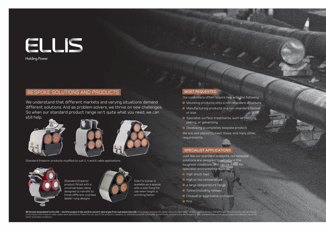
BESPOKE SOLUTIONS AND PRODUCTS
We understand that different markets and varying situations demand different solutions. And as problem solvers, we thrive on new challenges. So when our standard product range isn’t quite what you need, we can still help.
MOST REQUESTED
Our customers often require help with the following:
Mounting products onto a non-standard structure.
Manufacturing products in a non-standard format or size.
Specialist surface treatments, such as painting, plating, or galvanizing.
Developing a completely bespoke product.
We are well placed to meet these, and many other, requirements.
SPECIALIST APPLICATIONS
Just like our standard products, our bespoke solutions are designed to withstand the toughest conditions, and can be made for specialist environments such as:
High shock load
High or low temperature
A large temperature range
Tunnel (including railway)
Unusual or aggressive corrosion
Fire
Standard Emperor products modifi ed to suit 2, 4 and 6 cable applications.
Standard Emperor product fi tted with a universal base clamp designed to retrofi t to three different undrilled ladder rung designs.
Side Fix Vulcan is available as a special, with a side fi xing for use when height is a limiting factor.
BG Group’s Queensland Curtis LNG - the fi rst project in the world to convert natural gas from coal seams into LNG. Photograph showing the construction of some 540km of main pipeline network linking the gas fi elds to the QCLNG terminal on Curtis Island. Ellis Emperor cable cleats were specifi ed by Thiess Pty Ltd, due to the product’s capability to withstand possible 111kA peak system faults. Furthermore, the Emperor’s 316L stainless steel construction meant it is ideal for use in the harsh Australian conditions.
ww
w.e
llispa
tent
s.co
.uk
/4342
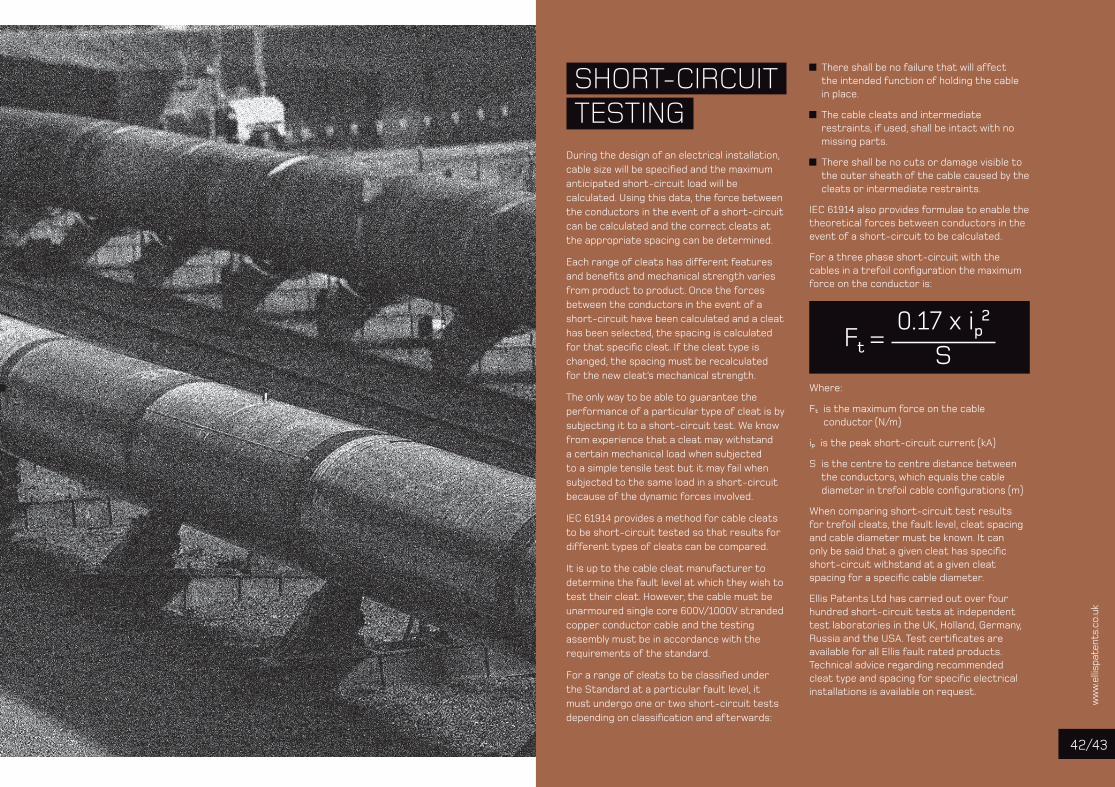
During the design of an electrical installation, cable size will be specified and the maximum anticipated short-circuit load will be calculated. Using this data, the force between the conductors in the event of a short-circuit can be calculated and the correct cleats at the appropriate spacing can be determined.
Each range of cleats has different features and benefits and mechanical strength varies from product to product. Once the forces between the conductors in the event of a short-circuit have been calculated and a cleat has been selected, the spacing is calculated for that specific cleat. If the cleat type is changed, the spacing must be recalculated for the new cleat’s mechanical strength.
The only way to be able to guarantee the performance of a particular type of cleat is by subjecting it to a short-circuit test. We know from experience that a cleat may withstand a certain mechanical load when subjected to a simple tensile test but it may fail when subjected to the same load in a short-circuit because of the dynamic forces involved.
IEC 61914 provides a method for cable cleats to be short-circuit tested so that results for different types of cleats can be compared.
It is up to the cable cleat manufacturer to determine the fault level at which they wish to test their cleat. However, the cable must be unarmoured single core 600V/1000V stranded copper conductor cable and the testing assembly must be in accordance with the requirements of the standard.
For a range of cleats to be classified under the Standard at a particular fault level, it must undergo one or two short-circuit tests depending on classification and afterwards:
There shall be no failure that will affect the intended function of holding the cable in place.
The cable cleats and intermediate restraints, if used, shall be intact with no missing parts.
There shall be no cuts or damage visible to the outer sheath of the cable caused by the cleats or intermediate restraints.
IEC 61914 also provides formulae to enable the theoretical forces between conductors in the event of a short-circuit to be calculated.
For a three phase short-circuit with the cables in a trefoil configuration the maximum force on the conductor is:
Where:
Ft is the maximum force on the cable conductor (N/m)
ip is the peak short-circuit current (kA)
S is the centre to centre distance between the conductors, which equals the cable diameter in trefoil cable configurations (m)
When comparing short-circuit test results for trefoil cleats, the fault level, cleat spacing and cable diameter must be known. It can only be said that a given cleat has specific short-circuit withstand at a given cleat spacing for a specific cable diameter.
Ellis Patents Ltd has carried out over four hundred short-circuit tests at independent test laboratories in the UK, Holland, Germany, Russia and the USA. Test certificates are available for all Ellis fault rated products. Technical advice regarding recommended cleat type and spacing for specific electrical installations is available on request.
SHORT-CIRCUIT TESTING
Ft =0.17 x ip2
S
FSC Logo to go here
Des
ign
by: w
ww
.viv
idcr
eati
ve.c
om ©
201
4 V1
0251
Ellis Patents LtdHigh Street, Rillington, MaltonNorth Yorkshire YO17 8LAUnited Kingdom
T. +44 (0)1944 758395F. +44 (0)1944 [email protected]
EP2014/01/11