eliche direzionali bow thrusters - accueil bow thrusters.pdf · prodotta poiché maggiore è la...
TRANSCRIPT

ELICHE DIREZIONALIBOW THRUSTERS
1
INDICE INDEX
Presentazione aziendaCompany profi le 2-3 IntroduzioneIntroduction 4
Thruster elettrici: selezione impiantoElectric thruster: system selection 5
Caratteristiche principaliMain features 6-7
Composizione impiantoSystem composition 8-9
Guida all’ordineOrder guide 10-11
AccessoriAccessories 12-14
Thruster idraulici: selezione impiantoHydraulic thruster: system selection 15
Caratteristiche principaliMain features 16-17
Composizione impiantoSystem composition 18
Guida all’ordineOrder guide 19
AccessoriAccessories 20-23
Parti di ricambioSpare parts 24-26
Dimensioni e specifi che tecnicheDimensions and technical specifi cations 27-29
Condizioni di garanziaWarranty conditions 30-31
Distributori internazionaliInternational distributors network 32
NOTA: Twin Disc S.r.l. declina ogni responsabilità per eventuali inesattezze, dovute a errori di stampa, contenute nel presente catalogo e si riserva il diritto di apportare ai propri articoli tutte le modifi che che riterrà opportune. I diritti di pubblicazione, i marchi, le sigle e le fotografi e presenti su questo catalogo sono di proprietà di Twin Disc S.r.l. o ne è stata autorizzata la pubblicazione: se ne vieta qualsiasi riproduzione anche parziale. I nostri articoli non possono essere utilizzati su imbarcazioni da competizione senza nostra previa autorizzazione.
NOTE: Twin Disc S.r.l. declines any liability for possible mistakes in this catalogue due to printing errors and reserves the right to make any modifi cation that is considered to be necessary or useful for its products. Publishing rights, trade marks, part numbers and photographs present on this catalogue are Twin Disc Srl property or it has the necessary authorization to use them. All rights are reserved and any reproduction, even partial, is forbidden. Our products cannot be installed on racing boats without our previous authorization.
2
1956, anno di fondazione di BCS S.r.l.2006, anno di acquisizione da parte di Twin Disc Inc.2007, anno di fusione in Twin Disc S.r.l.
Oltre cinquant’anni di esperienza e professionalità hanno portato BCS ai vertici della produzione e distribuzione mondiale di impianti nautici di alta qualità. L’acquisizione da parte di Twin Disc Inc. - leader nei settori: nautico, industriale, trasmissioni per movimento terra e per l’industriadell’estrazione del petrolio - ne ha consolidato la presenza sul mercato come parte di un gruppo multinazionale. La fusione tra BCS, BCS Service, Twin Disc Technodrive, Twin Disc Propulsion ha dato vita, in Italia, alla nuova Twin Disc S.r.l., un’azienda compatta supportata dal valore aggiunto della sister-company Rolla SP Propellers.
Global ‘package’Twin Disc S.r.l. offre a costruttori e progettisti un ‘package’ completo di prodotti, da sistemi propulsivi a invertitori e trasmissioni, fi no a sistemi di comando e controllo, insieme a soluzioni personalizzate e risposte tecniche effi caci. Un servizio globale al cliente, per lo sviluppo e la realizzazione di tutta la catena cinematica. Un team dinamico di ingegneri, tecnici e professionisti è dedicato ad assistere il cliente in ogni fase: dal concept alla progettazione, dallo sviluppo del prototipo alla defi nizione del design, dai test in offi cina e sul campo fi no alla produzione, installazione, montaggio e service, anche direttamente a bordo.
Giorno dopo giorno, Twin Disc S.r.l. lavora al fi anco del cliente. La capacità di recepire e anticipare le richieste del mercato, l’affi dabilità certifi cata dei prodotti, l’assistenza specializzata, la ricerca continua nell’innovazione tecnologica si affermano in un sistema unico al mondo dedicato all’industria della nautica.
Oltre 12 anni di esperienza nelle tecnologie di propulsione hanno portato allo sviluppo della gamma di thruster linea BCS elettrici e idraulici: affi dabili ed effi cienti permettono applicazioni dai 6 ai 40 mt 20’-132’. Design compatto e facilità di installazione li rendono i prodotti preferiti dai maggiori costruttori e dai principali cantieri navali. Thruster Twin Disc - linea BCS: libertà di manovra, potenza e precisione dei movimenti.
Dall’idea alla produzione: sviluppo del p
From the concept to the production:
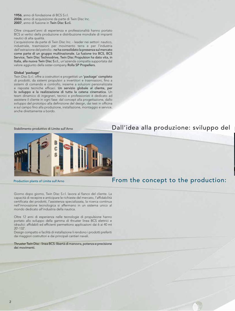
Stabilimento produttivo di Limite sull’Arno
Production plants of Limite sull’Arno
2
3
1956, BCS s.r.l. was founded2006, Twin Disc Inc. acquired BCS s.r.l.2007, Incorporation of BCS s.r.l. in Twin Disc S.r.l.
Besides fi fty years of experience and competence BCS has become a leading company in the production and worldwide distribution of high quality marine equipment. The acquisition by Twin Disc Inc. – leader in several different areas such as marine and industrial, heavy duty transmissions and the oil extraction industry – has consolidated its position on the market as a part of a multinational group. The merging of BCS, BCS Service, Twin Disc Technodrive, Twin Disc Propulsion has started, in Italy, the new Twin Disc S.r.l., a sound fi rm supported by the additional value of the sister-company Rolla SP Propellers.
Global “package”Twin Disc S.r.l. offers to boat builders and design engineers a complete ”package” of products, from propulsion systems to gearboxes and transmissions up to control and steering systems, together with customized solutions and effi cient technical support. A global customer service for the development and realization of the whole kinematics system. A dynamic team of engineers, technicians and professional people is devoted to support the customer in any step: from concept of the project to the planning, through prototype development and design defi nition, up to bench and fi eld testing, production, assembly, installation and service also on board. Day by day, Twin Disc S.r.l. works alongside the customer.
The ability to acknowledge and anticipate market requests, the certifi ed reliability of products, the skilled service and the continuous research of technological innovation establish themselves in a unique worldwide system dedicated to the marine industry.
Over 12 years of experience in propulsion technologies have brought BCS to the development of the thrusters line: reliable and performing, they are suitable for application from 6 to 40 mt 20’-132’. A compact design and an easy installation make the BCS thrusters the largely used products by the major boatyard.
Twin Disc - BCS thrusters: manoeuvre freedom, power and accurate movements.
l prototipo, cura del design, test sul campo, realizzazione del prodotto
prototype development, care for design, field testing, product definition

4
INTRODUZIONE
Le eliche direzionali di prua e di poppa sono indispensabili per assicurare comfort di manovra e controllo completo in presenza di forti venti e correnti, non solo in acque aperte ma anche nei porti e nelle piccole marine, senza sforzo in fase di attracco o sul punto di salpare.
Premendo un pulsante o muovendo il joystick del pannello di controllo si spostano lateralmente la prua o la poppa della barca per effettuare movimenti agili.
Il design compatto ne permette l’installazione anche in spazi ristretti, l’esperienza e il grande numero di applicazioni sono garanzia di alta qualità.
Twin Disc offre un’ampia scelta di eliche direzionali elettriche e idrauliche all’interno della gamma BCS: per imbarcazioni più piccole e fi no a oltre 40 mt di lunghezza.
Nelle applicazioni dove è richiesto un tempo di attuazione molto lungo e sono necessari valori di spinta molto alti, ad esempio, Twin Disc offre e suggerisce diverse opzioni di eliche di prua e di poppa idrauliche. In questo caso, infatti, un propulsore elettrico richiederebbe grossi cavi di collegamento e la presenza a bordo di un generatore, causando pesi e ingombri fastidiosi oltre a costi più alti. Un impianto idraulico, invece, prende la potenza necessaria direttamente dal motore: risulta quindi la soluzione ideale.
INTRODUCTION
Bow and stern thruster becomes absolutely necessary to ensure the best manoeuvrability and total comfort, in presence of strong winds and streams, not only in open sea but also in the harbours and the small marinas, while mooring or setting sail.
It’s enough to push a button or to move the joystick of the control panel on the dashboard to move the bow or stern sideways and to perform nimble manoeuvres.
Their compact design allow them to be installed in limited spaces, too, while the great experience gained during many years of production and the large number of applications are a guarantee of high quality and trouble-free performances.
Twin Disc offer a wide choice of bow and stern thrusters in BCS range, both electric and hydraulic, covering a large range of applications from the very small ones up to the 40 mt of length.
In all those applications where a longer working cycle and a much higher thrust are required, for example, Twin Disc offers and suggests the installation of a hydraulic system. An electric thruster would actually require very big connection wires, as well as a generator set, in order to satisfy the higher power request, with noticeable weight and dimensions and quite burdensome costs; instead, an hydraulic system, that takes all the necessary power from tha main engine,results to be the ideal solution.
ELECTRICTHRUSTER
HYDRAULICTHRUSTER
5
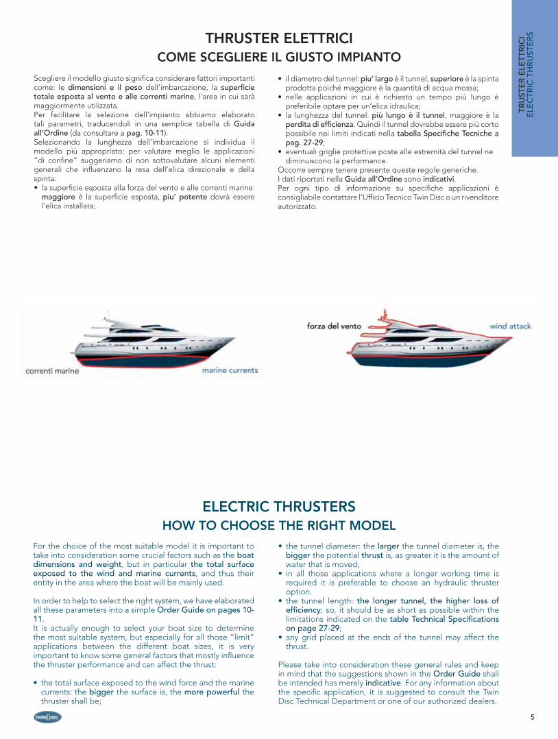
Scegliere il modello giusto signifi ca considerare fattori importanti come: le dimensioni e il peso dell’imbarcazione, la superfi cie totale esposta al vento e alle correnti marine, l’area in cui sarà maggiormente utilizzata. Per facilitare la selezione dell’impianto abbiamo elaborato tali parametri, traducendoli in una semplice tabella di Guida all’Ordine (da consultare a pag. 10-11).Selezionando la lunghezza dell’imbarcazione si individua il modello più appropriato: per valutare meglio le applicazioni “di confi ne” suggeriamo di non sottovalutare alcuni elementi generali che infl uenzano la resa dell’elica direzionale e della spinta:• la superfi cie esposta alla forza del vento e alle correnti marine:
maggiore è la superfi cie esposta, piu’ potente dovrà essere l’elica installata;
• il diametro del tunnel: piu’ largo è il tunnel, superiore è la spinta prodotta poiché maggiore è la quantità di acqua mossa;
• nelle applicazioni in cui è richiesto un tempo più lungo è preferibile optare per un’elica idraulica;
• la lunghezza del tunnel: più lungo è il tunnel, maggiore è la perdita di effi cienza. Quindi il tunnel dovrebbe essere più corto possibile nei limiti indicati nella tabella Specifi che Tecniche a pag. 27-29;
• eventuali griglie protettive poste alle estremità del tunnel ne diminuiscono la performance.
Occorre sempre tenere presente queste regole generiche.I dati riportati nella Guida all’Ordine sono indicativi. Per ogni tipo di informazione su specifi che applicazioni è consigliabile contattare l’Uffi cio Tecnico Twin Disc o un rivenditore autorizzato.
THRUSTER ELETTRICICOME SCEGLIERE IL GIUSTO IMPIANTO
For the choice of the most suitable model it is important to take into consideration some crucial factors such as the boat dimensions and weight, but in particular the total surface exposed to the wind and marine currents, and thus their entity in the area where the boat will be mainly used.
In order to help to select the right system, we have elaborated all these parameters into a simple Order Guide on pages 10-11.It is actually enough to select your boat size to determine the most suitable system, but especially for all those “limit” applications between the different boat sizes, it is very important to know some general factors that mostly infl uence the thruster performance and can affect the thrust:
• the total surface exposed to the wind force and the marine currents: the bigger the surface is, the more powerful the thruster shall be;
• the tunnel diameter: the larger the tunnel diameter is, the bigger the potential thrust is, as greater it is the amount of water that is moved;
• in all those applications where a longer working time is required it is preferable to choose an hydraulic thruster option.
• the tunnel length: the longer tunnel, the higher loss of effi ciency; so, it should be as short as possible within the limitations indicated on the table Technical Specifi cations on page 27-29;
• any grid placed at the ends of the tunnel may affect the thrust.
Please take into consideration these general rules and keep in mind that the suggestions shown in the Order Guide shall be intended has merely indicative. For any information about the specifi c application, it is suggested to consult the Twin Disc Technical Department or one of our authorized dealers.
ELECTRIC THRUSTERSHOW TO CHOOSE THE RIGHT MODEL
TRU
STE
R E
LETT
RIC
IE
LEC
TRIC
TH
RU
STE
RS
6
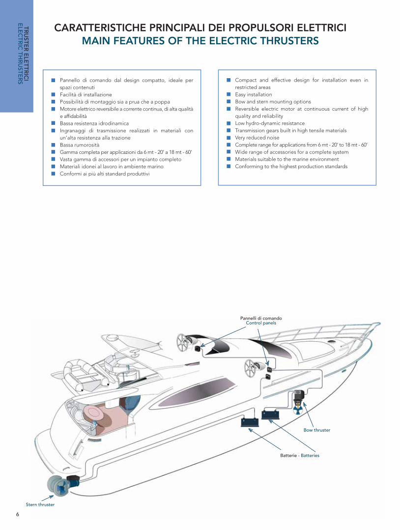
CARATTERISTICHE PRINCIPALI DEI PROPULSORI ELETTRICIMAIN FEATURES OF THE ELECTRIC THRUSTERS
Pannelli di comandoControl panels
Batterie - Batteries
Bow thruster
Stern thruster
TRU
STER
ELE
TTRIC
IE
LEC
TRIC
THR
USTE
RS Pannello di comando dal design compatto, ideale per
spazi contenutiFacilità di installazionePossibilità di montaggio sia a prua che a poppaMotore elettrico reversibile a corrente continua, di alta qualità e affi dabilitàBassa resistenza idrodinamica Ingranaggi di trasmissione realizzati in materiali con un’alta resistenza alla trazioneBassa rumorositàGamma completa per applicazioni da 6 mt - 20’ a 18 mt - 60’Vasta gamma di accessori per un impianto completo Materiali idonei al lavoro in ambiente marino Conformi ai più alti standard produttivi
Compact and effective design for installation even in restricted areasEasy installationBow and stern mounting optionsReversible electric motor at continuous current of high quality and reliabilityLow hydro-dynamic resistance Transmission gears built in high tensile materialsVery reduced noiseComplete range for applications from 6 mt - 20’ to 18 mt - 60’Wide range of accessories for a complete system Materials suitable to the marine environment Conforming to the highest production standards
7
MANOVRABILITÀ COMPLETACOMPLETE MOVEMENT FREEDOM
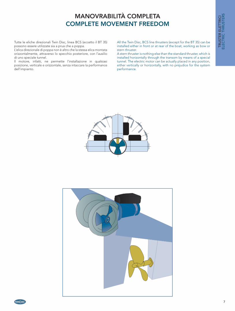
Tutte le eliche direzionali Twin Disc, linea BCS (eccetto il BT 35) possono essere utilizzate sia a prua che a poppa.L’elica direzionale di poppa non è altro che la stessa elica montata orizzontalmente, attraverso lo specchio posteriore, con l’ausilio di uno speciale tunnel.Il motore, infatti, ne permette l’installazione in qualsiasi posizione, verticale e orizzontale, senza intaccare la performance dell’impianto.
All the Twin Disc, BCS line thrusters (except for the BT 35) can be installed either in front or at rear of the boat, working as bow or stern thruster.A stern thruster is nothing else than the standard thruster, which is installed horizontally through the transom by means of a special tunnel. The electric motor can be actually placed in any position, either vertically or horizontally, with no prejudice for the system performance.
TRU
STE
R E
LETT
RIC
IE
LEC
TRIC
TH
RU
STE
RS

8
Tutte le eliche direzionali della linea BCS sono pensate e realizzate per una facile installazione anche in ambienti ristretti. Il propulsore, nella versione base, è composto dagli elementi indicati nel dettaglio.È disponibile una serie di accessori per completare il sistema: pannelli di comando, dispositivo di ritardo, cavi di collegamento. Gli accessori sono descritti alle pag. 12-14.
All the bow and stern thrusters of the BCS line have a compact design, allowing an easy installation even with a very limited room. The thruster, in its basic version, is composed with the elements here listed.The system can be integrated with a large range of accessories, such as control panels, time-lapse devices, connection cables. All the available accessories are described on pages 12-14.
1
TRU
STER
ELE
TTRIC
IE
LEC
TRIC
THR
USTE
RS
3
La fl angia motore è montata direttamente sul piede del thruster (4), serve a reggere il motore e a fi ssarlo al tunnel. È costruita in una lega speciale e ha una struttura robusta per garantire la massima stabilità.
The motor fl ange is directly fi tted on the thruster leg (4) and has the function of supporting the electric motor itself an fi x it to the tunnel. It is built in a special alloy and has a strong structure to ensure the best stability.
2
Il relé di accensione che si trova dietro il carter serve ad avviare il motorino elettrico e permette l’inversione del senso di rotazione.
The start-up relay placed behind the cover has the function to start the electric motor, as well as the one of allowing the inversion of the rotation direction.
Il motore elettrico è del tipo reversibile a corrente continua, disponibile a 12V e a 24V.Specifi camente costruito per un uso continuo al massimo della potenza, rispetta gli standard produttivi più alti per assicurare effi cienza e lunga durata. Sull’etichetta del motore sono indicati i tempi di utilizzo.
The electric motor is of the reversible type at continuous current, available at 12V or 24V. It is suitable for a continuous running at max speed. The quality level is very high, according to the best production standards, in order to ensure a effi ciency and a longer, trouble-free life. Working times are shown on the motor label.
4Il piede del thruster è in bronzo e presenta una forma affusolata per ridurre la resistenza idrodinamica al minimo e garantire una resa migliore. Per proteggerlo dalla corrosione elettrolitica, viene installato un anodo di zinco.Tutti gli ingranaggi interni di trasmissione sono realizzati in materiali altamente resistenti alla trazione e sono trattati in modo tale da assicurarne una lunga durata anche in condizioni di lavoro pesanti. Lo studio di ogni componente è fi nalizzato alla riduzione al minimo del livello di rumorosità. Gli ingranaggi di trasmissione sono protetti da giunti elastici o spine.
The thruster leg is in bronze and it is provided with a particular design, which reduces the hydrodynamic resistance to a minimum in order to ensure a better effi ciency. It is provided with a zinc anode for protection against electrolytic corrosion.All the transmissions gears inside the leg are realized in high tensile materials and are treated to provide a long working life even under heavy-duty conditions. Particular care is also given to their design, so as to considerably reduce the noise.The transmission gears are protected by elastic couplings, as well as a shear and a drive pin.
SYSTEM COMPOSITIONCOMPOSIZIONE IMPIANTO

9
PCSSISTEMA DI CONTROLLO PCS
TRU
STE
R E
LETT
RIC
IE
LEC
TRIC
TH
RU
STE
RS CONTROL SYSTEM
Per garantire un alto livello di sicurezza l’intera linea di thruster elettrici è dotata dell’innovativo dispositivo di controllo PCS. Il PCS controlla che le temperature siano a livello e regola, se necessario, accensione e spegnimento. In caso di surriscaldamento, ad esempio, il PCS spegne il thruster evitando danni maggiori.
In order to ensure an higher safety level the whole range of electric thrusters has been provided with a new PCS control system. This new device checks temperature levels and, when necessary, regulate switching on-off. In case of a sudden rise in temperature, for example, the PCS device shuts down the thruster avoiding damages.
6
Il piccolo serbatoio in plastica (6) contiene il liquido idraulico per la lubrifi cazione degli ingranaggi del piede, a cui è collegato per mezzo di un tubo (7). Il kit è incluso nella fornitura standard: Twin Disc ne suggerisce l’installazione per garantire una più lunga durata ed effi cienza del thruster. Il piede del thruster è già pieno di olio e l’elica lavora anche senza l’utilizzo del kit. Quando il kit è montato, però, eventuali perdite dalle guarnizioni del piede possono essere immediatamente evidenziate dall’abbassamento del livello all’interno del serbatoio.
The small plastic tank (6) contains the hydraulic fl uid for the gears lubrication of the leg, which is connected to by means of a fl exible hose (7), and has the important function to reduce friction and ensure a longer life and a better effi ciency of the thruster. This kit is already included in the standard thruster set and Twin Disc suggests its installation as an additional safety measure. The thruster can actually work even without the lubricating kit, as the leg is already fi lled with oil. However, when the kit is installed any possible oil leak from the leg seals can be immediately discovered by the lowering of the oil level into the tank.
7
5
L’elica è di primaria importanza ai fi ni del rendimento del thruster. È realizzata in materiale composito: molto leggera, senza problemi di corrosione, garantisce una spinta uguale in entrambe le direzioni senza creare alcun effetto di cavitazione, che provocherebbe una perdita di spinta rilevante oltre a rumore e fastidiose vibrazioni.
Of great importance for the best effi ciency of the system is the three-blades propeller, too. It is made of a compound material and is therefore very light and free from corrosion problems, while its design guarantees an equal thrust on both sides.Great attention was also paid to the attempt of avoiding any cavitation effect, which would result in a considerable loss of thrust, as well as noise and tiresome vibrations.

10
Unità di misura
MeasureBT 35N BT 55N BT
Lunghezza barca*Typical boat size*
Open(mt • ft)
6 - 10 • 20’ -33’ 9 - 12 • 30’ - 38’ 11 - 14 •
Fly 6 - 9 • 20’ - 30’ 8 - 11 • 26’ - 36’ 10 - 13 •
Sail 4,5 - 8 • 15’ - 26’ 7 - 10 • 23’ - 33’ 9 - 12 •
Spinta Thrust (Kgf • lbs • N) 35 • 78 • 343 55 • 122 • 540 85 • 188
Tunnel I.D.Tunnel I.D. (mm • in) 125 • 4,92” 185 • 7,28” 185 •
PotenzaPower (KW • Hp) 2,2 • 3 3 • 4 5,3 • 7,1(12V) – 4,8
VoltaggioVoltage (V) 12 12 • 24 • 12
Cavo batterie: lunghezza max dal positivo e negativo in (m) data la sezione (mm2) m 6 9 14 18 5 7 10 14 18 22 N/
RN/R 4 6 8 10 16 20 25 29 12 1
Battery cable: max lenght from positive and negative in (m) given the cable section (mm2) mm2 25 35 50 70 25 35 50 70 25 35 50 70 25 35 50 70 95 120150 175 25 3
FusibileFuse (A) 250 250 125 355
Assorbimento Power consumption (A) 273 (12V) 350 (12V) • 175 (24V) 580 (12V) •
PesoWeight (Kg • lb) 10,5 • 23,2 20 • 44 25 • 55,1
GUIDA ALL’ORDINE - ORDER GUIDE
Modello Model Descrizione - Description Codice
Code
BT 35N/12Bow thruster elettrico 35 Kgf a 12 VdcElectric bow thruster 35 Kgf at 12 Vdc 25657
BT 55N/12Bow thruster elettrico 55 Kgf a 12 VdcElectric bow thruster 55 Kgf at 12 Vdc 25658
BT 55N/24Bow thruster elettrico 55 Kgf a 24 VdcElectric bow thruster 55 Kgf at 24 Vdc 25659
BT 85N/12Bow thruster elettrico 85 Kgf a 12 VdcElectric bow thruster 85 Kgf at 12 Vdc 25660
BT 85N/24Bow thruster elettrico 85 Kgf a 24 VdcElectric bow thruster 85 Kgf at 24 Vdc 25661
BT 100N/12Bow thruster elettrico 100 Kgf a 12 VdcElectric bow thruster 100 Kgf at 12 Vdc 25662
BT 100N/24Bow thruster elettrico 100 Kgf a 24 VdcElectric bow thruster 100 Kgf at 24 Vdc 25663
BT 120N/24Bow thruster elettrico 120 Kgf a 24 VdcElectric bow thruster 120 Kgf at 24 Vdc 25664
BT 160N/24Bow thruster elettrico 160 Kgf a 24 VdcElectric bow thruster 160 Kgf at 24 Vdc 25665
* Valori indicativi. Le performance di ogni impianto dipendono da diversi altri fattori.
Dotati del nuovo sistema di controllo PCS che garantisce maggiore sicurezza a bordo.
Provided with a new PCS control system that garantees a higher safety on board.
PCS
PCS PCS
TRU
STER
ELE
TTRIC
IE
LEC
TRIC
THR
USTE
RS
11
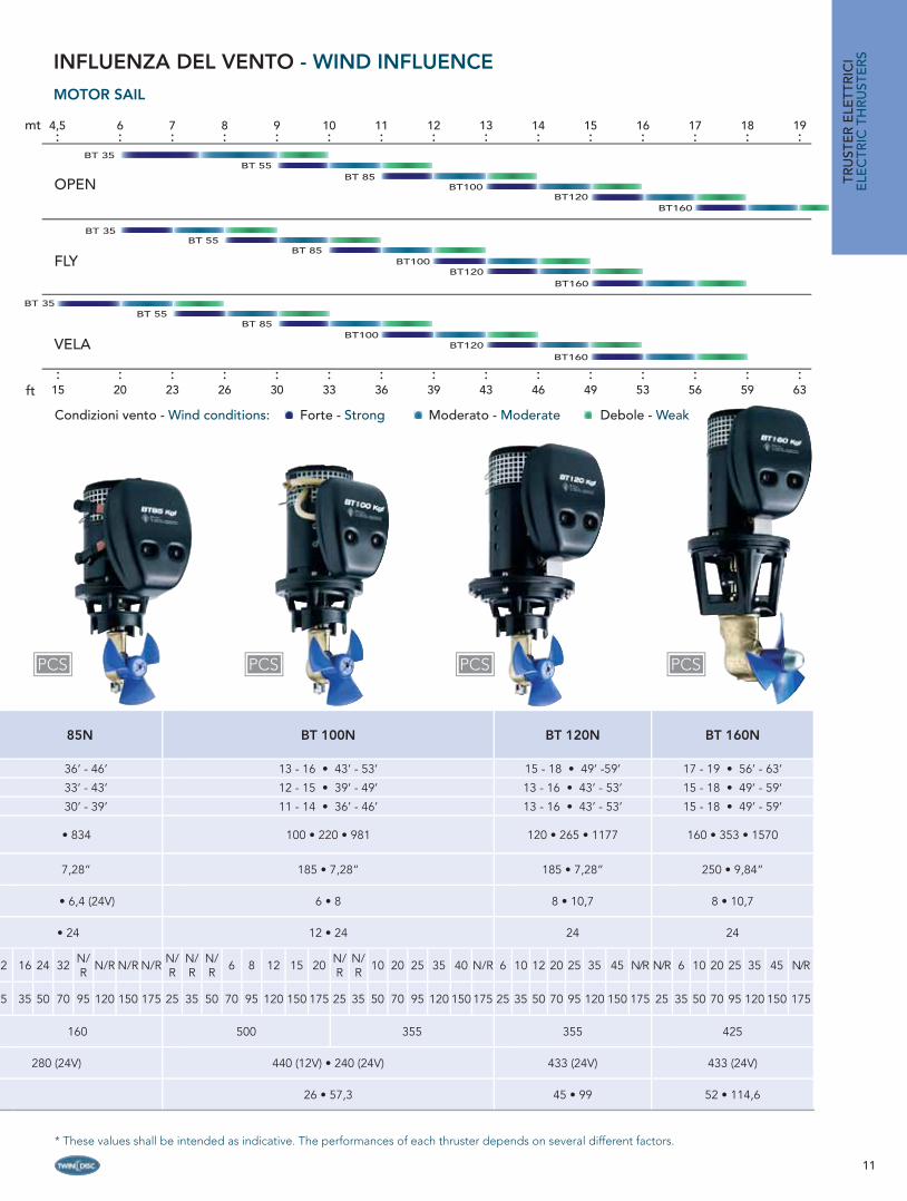
85N BT 100N BT 120N BT 160N
36’ - 46’ 13 - 16 • 43’ - 53’ 15 - 18 • 49’ -59’ 17 - 19 • 56’ - 63’
33’ - 43’ 12 - 15 • 39’ - 49’ 13 - 16 • 43’ - 53’ 15 - 18 • 49’ - 59’
30’ - 39’ 11 - 14 • 36’ - 46’ 13 - 16 • 43’ - 53’ 15 - 18 • 49’ - 59’
• 834 100 • 220 • 981 120 • 265 • 1177 160 • 353 • 1570
7,28” 185 • 7,28” 185 • 7,28” 250 • 9,84”
• 6,4 (24V) 6 • 8 8 • 10,7 8 • 10,7
• 24 12 • 24 24 24
2 16 24 32 N/R N/R N/R N/R N/
RN/R
N/R 6 8 12 15 20 N/
RN/R 10 20 25 35 40 N/R 6 10 12 20 25 35 45 N/R N/R 6 10 20 25 35 45 N/R
5 35 50 70 95 120 150 175 25 35 50 70 95 120 150 175 25 35 50 70 95 120 150 175 25 35 50 70 95 120 150 175 25 35 50 70 95 120 150 175
160 500 355 355 425
280 (24V) 440 (12V) • 240 (24V) 433 (24V) 433 (24V)
26 • 57,3 45 • 99 52 • 114,6
* These values shall be intended as indicative. The performances of each thruster depends on several different factors.
INFLUENZA DEL VENTO - WIND INFLUENCEMOTOR SAIL
Condizioni vento - Wind conditions: Forte - Strong Debole - WeakModerato - Moderate
6:
9:
10:
12:
13:
15:
17:
19:
mt
ft
8:
11:
14:
18:
16:
OPEN
BT 35BT 55
BT 85BT100
BT120BT160
FLY
BT 35BT 55
BT 85BT100
BT120BT160
:20
:30
:33
:39
:43
:49
:56
:63
:26
:36
:46
:59
:53
VELA
7:
4,5:
:15
:23
BT 35BT 55
BT 85BT100
BT120BT160
PCSPCS PCS PCS
TRU
STE
R E
LETT
RIC
IE
LEC
TRIC
TH
RU
STE
RS

12
ACCESSORI - ACCESSORIES
Design compatto per i pannelli di comando, progettati per offrire alti livelli di qualità e affi dabilità a bordo. Facili da installare grazie a un rapido montaggio frontale senza viti di fi ssaggio, sono disponibili sia nella versione con il joystick sia con touch pad. Per un controllo dell’elica di prua e di poppa contemporaneo è disponibile la versione con doppio joystick.
CARATTERISTICHE PRINCIPALI• Resistenza ai raggi UV• Grado di protezione IP65• Sistema di accensione child-proof• Timer di spegnimento dopo 10 min. con preavviso acustico• Interruzione automatica dopo 3 min. di funzionamento continuo in un senso• Allarme acustico di surriscaldamento motore• Dispositivo di ritardo per inversione comando• Fornito di cavetti pre-assemblati a innesto rapido, predisposto per più stazioni di comando
Cavi collegamento pannelli di comando - Control panel loomsI cavi elettrici di collegamento sono disponibili in diverse lunghezze da 6 mt - 20’ a 18 mt - 54’ e sono dotati di terminali ‘fast-lock’ per un veloce collegamento con i pannelli di comando.
The electric connection cables are available in several different lengths from 6 mt - 20’ to 18 mt - 54’ and are provided with “fast-lock” terminals for a fast connection to the control panels.
Descrizione - Description CodiceCode
Cavo elettrico collegamento completo di connettori L= 6 mt - 20 ftElectric connection cable provided with connectors L= 6 mt - 20 ft 25524
Cavo elettrico collegamento completo di connettori L= 10 mt - 33 ftElectric connection cableprovided with connectors L= 10 mt - 33 ft 25525
Cavo elettrico collegamento completo di connettori L= 18 mt - 54 ftElectric connection cable provided with connectors L= 18 mt - 54 ft 25526
A compact design for the control panels that have been projected to guarantee a higher quality level and improve safety on board. Very easy to install, thanks to the fast front mounting with no screws. The panels are available in two different models: the version with joystick or the one with touch pad. For a simple control of both the thrusters the right choice is the dual joystick panel.
MAIN FEATURES• UV ray resistant• Waterproof type IP65• Child-safe on/off system• Automatic deactivation with acoustic alarm after 10 minutes• Automatic deactivation with acoustic alarm after 3 minutes of continuous running in one direction• Acoustic alarm for motor overheating• Built in time delay • Provided with fast-lock wires suitable for one or more control stations
AC
CE
SSOR
IA
CC
ESSO
RIE
S Pannelli di comando Control panels
Modello Model Descrizione - Description Codice
Code
BTJOYN Pannello di comando thruster con joystick - Thruster control panel with joystick 25513
BTINTN Pannello di comando thruster con pulsanti - Thruster control panel with touch pad 25514
BTJOY2N Pannello di comando thruster con doppio joystick - Thruster control panel with dual joystick 25689
13
Fusibile - Porta fusibile Fuse - Fuse holder
Bow thruster Fusibile - Fuse
Bow thruster Codice - Code Descizione - Description Codice fusibile
Fuse codeAssorbimento
Power consumption
Codice portafusibileFuse holder
code25657 Bow thruster 35 Kgf - 12V 24980 Fusibile - Fuse 250 A
24984
25658 Bow thruster 55 Kgf - 12V 24980 Fusibile - Fuse 250 A
25659 Bow thruster 55 Kgf - 24V 24978 Fusibile - Fuse 125 A
25660 Bow thruster 85 Kgf - 12V 24981 Fusibile - Fuse 355 A
25661 Bow thruster 85 Kgf - 24V 24979 Fusibile - Fuse 160 A
25662 Bow thruster 100 Kgf - 12V 24983 Fusibile - Fuse 500 A
25663 Bow thruster 100 Kgf - 24V 24981 Fusibile - Fuse 355 A
25664 Bow thruster 120 Kgf - 24V 24981 Fusibile - Fuse 355 A
25665 Bow thruster 160 Kgf - 24V 24982 Fusibile - Fuse 425 A
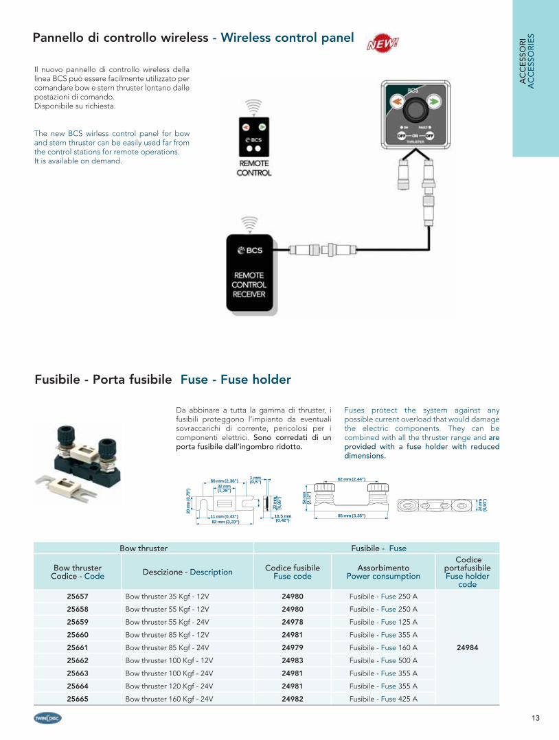
Da abbinare a tutta la gamma di thruster, i fusibili proteggono l’impianto da eventuali sovraccarichi di corrente, pericolosi per i componenti elettrici. Sono corredati di un porta fusibile dall’ingombro ridotto.
Fuses protect the system against any possible current overload that would damage the electric components. They can be combined with all the thruster range and are provided with a fuse holder with reduced dimensions.
1 mm(0,5”)60 mm (2,36”)
32 mm(1,26”)
82 mm (3,23”)11 mm (0,43”)
20 m
m (0
,79”
)
22 m
m(0
,86”
)
10,5 mm(0,42”)
85 mm (3,35”)
62 mm (2,44”)
54 m
m(2
,12”
)
24 m
m(0
,94”
)
AC
CE
SSO
RI
AC
CE
SSO
RIE
SPannello di controllo wireless - Wireless control panel
Il nuovo pannello di controllo wireless della linea BCS può essere facilmente utilizzato per comandare bow e stern thruster lontano dalle postazioni di comando. Disponibile su richiesta.
The new BCS wirless control panel for bow and stern thruster can be easily used far from the control stations for remote operations.It is available on demand.

14
Kit elica di poppa - Stern thruster kit
Descrizione - Description Codice Code
Kit elica di poppa per BT 55 - BT 85 - BT 100 - BT 120 d. 185 mm - 7,28 inStern Thruster kit for BT 55 - BT 85 - BT 100 - BT 120 d. 185 mm - 7,28 in 25492
Kit elica di poppa per BT 160 d. 250 mm - 9,84 inStern Thruster kit for BT 160 d. 250 mm - 9,84 in 25499
Tunnel in materiale composito per l’installazione dello stern thruster, completo di fl angia di accoppiamento allo specchio di poppa e viti di fi ssaggio. Disponibile nei diametri da 185 mm e 250 mm.
Stern-thruster installation kit in composite material, provided with coupling fl ange and fi xing screws for connection to the transom. Available in diameters of 185 mm and 250 mm.
175
mm
(6,8
9”)
3 mm (0,12”)
330
mm
(13”
)
470 mm (18,50”)
30°
30°92 mm (3,62”)
ø51 (2”)
130
mm
(5,1
1”)
3 mm (0,12”)
240
mm
(9,4
4”)
44 mm(1,73”)
340 mm (13,38”)
30°
30°
ø30 (1,81”)
Kit ingrassaggio - Leg lubricating kit
Il kit di ingrassaggio del piede è incluso nella fornitura standard. Serve a mantenere gli ingranaggi di trasmissione lubrifi cati per ridurre l’attrito e garantire una lunga durata dell’impianto (vedi “Composizione impianto” a pag. 8-9 per maggiori dettagli).Idoneo per tutti i modelli.
The thruster leg lubricating kit is included in the standard thruster set and has the function to maintain the transmission gears well lubricated, in order to reduce the friction and guarantee a longer life of the system (see “System composition” on page 8-9 for further details). Suitable for any model.
Descrizione - Description Codice Code
Kit ingrassaggio piede bow thruster per BT 35Thruster leg lubricating kit for BT 35 21466
Kit ingrassaggio piede bow thruster per BT 55 - BT 85 - BT 100 - BT 120 - BT 160Thruster leg lubricating kit for BT 55 - BT 85 - BT 100 - BT 120 - BT 160 10393
AC
CE
SSOR
IA
CC
ESSO
RIE
S
Bow thruster tunnel
Tunnel in vetroresina rinforzata disponibile nei diametri 125 mm - 185 mm - 250 mm (4,92” - 7,28” - 9,84”) e in varie lunghezze standard. È possibile richiedere lunghezze su misura.
Tunnels in reinforced GRP available in the diameters 125 mm - 185 mm - 250 mm (4,92” - 7,28” - 9,84”) in different standard lengths. Specifi c lengths can be supplied on demand.
Tunnel al metro - Tunnel per meter Codice Code
Tunnel in vetroresina d. 125 mm - GRP tunnel d. 125 mm 21474
Tunnel in vetroresina d. 185 mm - GRP tunnel d. 185 mm 23891
Tunnel in vetroresina d. 250 mm - GRP tunnel d. 250 mm 15304
Lunghezze standard - Standard lengths
BT 35
Tunnel in vetroresina d. 125 mm - GRP tunnel d. 125 mm L= 1 mt 21345
Tunnel in vetroresina d. 125 mm - GRP tunnel d. 125 mm L= 1,5 mt 27853
BT 55 - BT 85 - BT 100 - BT 120
Tunnel in vetroresina d. 185 mm - GRP tunnel d. 185 mm L= 1 mt 23892
Tunnel in vetroresina d. 185 mm - GRP tunnel d. 185 mm L= 1,5 mt 23893
BT 160
Tunnel in vetroresina con foratura d. 250 mmGRP pre-holed tunnel d. 250 mm
L= 2 mtL= 2 mt 21349
Tunnel in vetroresina con foratura d. 250 mmGRP pre-holed tunnel d. 250 mm
L= 1,5 mtL= 1,5 mt 21348
15
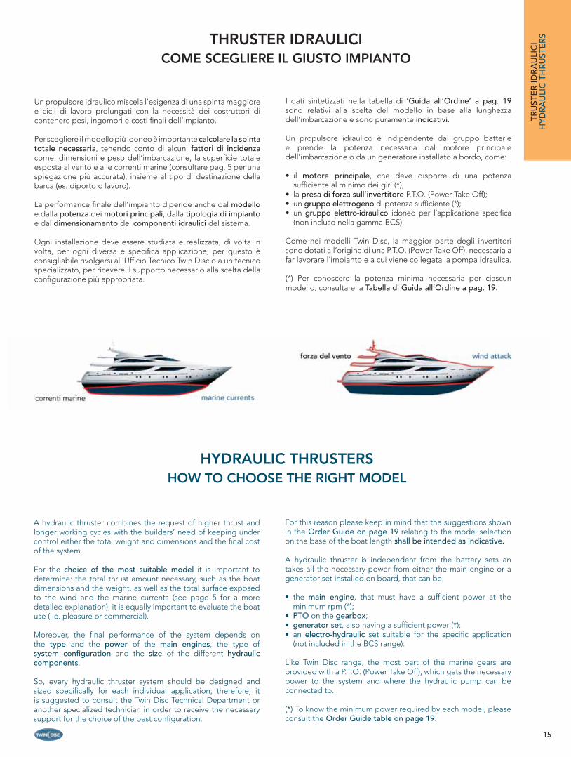
Un propulsore idraulico miscela l’esigenza di una spinta maggiore e cicli di lavoro prolungati con la necessità dei costruttori di contenere pesi, ingombri e costi fi nali dell’impianto.
Per scegliere il modello più idoneo è importante calcolare la spinta totale necessaria, tenendo conto di alcuni fattori di incidenza come: dimensioni e peso dell’imbarcazione, la superfi cie totale esposta al vento e alle correnti marine (consultare pag. 5 per una spiegazione più accurata), insieme al tipo di destinazione della barca (es. diporto o lavoro).
La performance fi nale dell’impianto dipende anche dal modello e dalla potenza dei motori principali, dalla tipologia di impianto e dal dimensionamento dei componenti idraulici del sistema.
Ogni installazione deve essere studiata e realizzata, di volta in volta, per ogni diversa e specifi ca applicazione, per questo è consigliabile rivolgersi all’Uffi cio Tecnico Twin Disc o a un tecnico specializzato, per ricevere il supporto necessario alla scelta della confi gurazione più appropriata.
I dati sintetizzati nella tabella di ‘Guida all’Ordine’ a pag. 19 sono relativi alla scelta del modello in base alla lunghezza dell’imbarcazione e sono puramente indicativi.
Un propulsore idraulico è indipendente dal gruppo batterie e prende la potenza necessaria dal motore principale dell’imbarcazione o da un generatore installato a bordo, come:
• il motore principale, che deve disporre di una potenza suffi ciente al minimo dei giri (*);
• la presa di forza sull’invertitore P.T.O. (Power Take Off);• un gruppo elettrogeno di potenza suffi ciente (*);• un gruppo elettro-idraulico idoneo per l’applicazione specifi ca
(non incluso nella gamma BCS).
Come nei modelli Twin Disc, la maggior parte degli invertitori sono dotati all’origine di una P.T.O. (Power Take Off), necessaria a far lavorare l’impianto e a cui viene collegata la pompa idraulica.
(*) Per conoscere la potenza minima necessaria per ciascun modello, consultare la Tabella di Guida all’Ordine a pag. 19.
THRUSTER IDRAULICICOME SCEGLIERE IL GIUSTO IMPIANTO
HYDRAULIC THRUSTERSHOW TO CHOOSE THE RIGHT MODEL
A hydraulic thruster combines the request of higher thrust and longer working cycles with the builders’ need of keeping under control either the total weight and dimensions and the fi nal cost of the system.
For the choice of the most suitable model it is important to determine: the total thrust amount necessary, such as the boat dimensions and the weight, as well as the total surface exposed to the wind and the marine currents (see page 5 for a more detailed explanation); it is equally important to evaluate the boat use (i.e. pleasure or commercial).
Moreover, the fi nal performance of the system depends on the type and the power of the main engines, the type of system confi guration and the size of the different hydraulic components.
So, every hydraulic thruster system should be designed and sized specifi cally for each individual application; therefore, it is suggested to consult the Twin Disc Technical Department or another specialized technician in order to receive the necessary support for the choice of the best confi guration.
For this reason please keep in mind that the suggestions shown in the Order Guide on page 19 relating to the model selection on the base of the boat length shall be intended as indicative.
A hydraulic thruster is independent from the battery sets an takes all the necessary power from either the main engine or a generator set installed on board, that can be:
• the main engine, that must have a suffi cient power at the minimum rpm (*);
• PTO on the gearbox;• generator set, also having a suffi cient power (*);• an electro-hydraulic set suitable for the specifi c application
(not included in the BCS range).
Like Twin Disc range, the most part of the marine gears are provided with a P.T.O. (Power Take Off), which gets the necessary power to the system and where the hydraulic pump can be connected to.
(*) To know the minimum power required by each model, please consult the Order Guide table on page 19.
TRU
STE
R ID
RA
ULI
CI
HY
DR
AU
LIC
TH
RU
STE
RS
16
CARATTERISTICHE PRINCIPALI - MAIN FEATURES
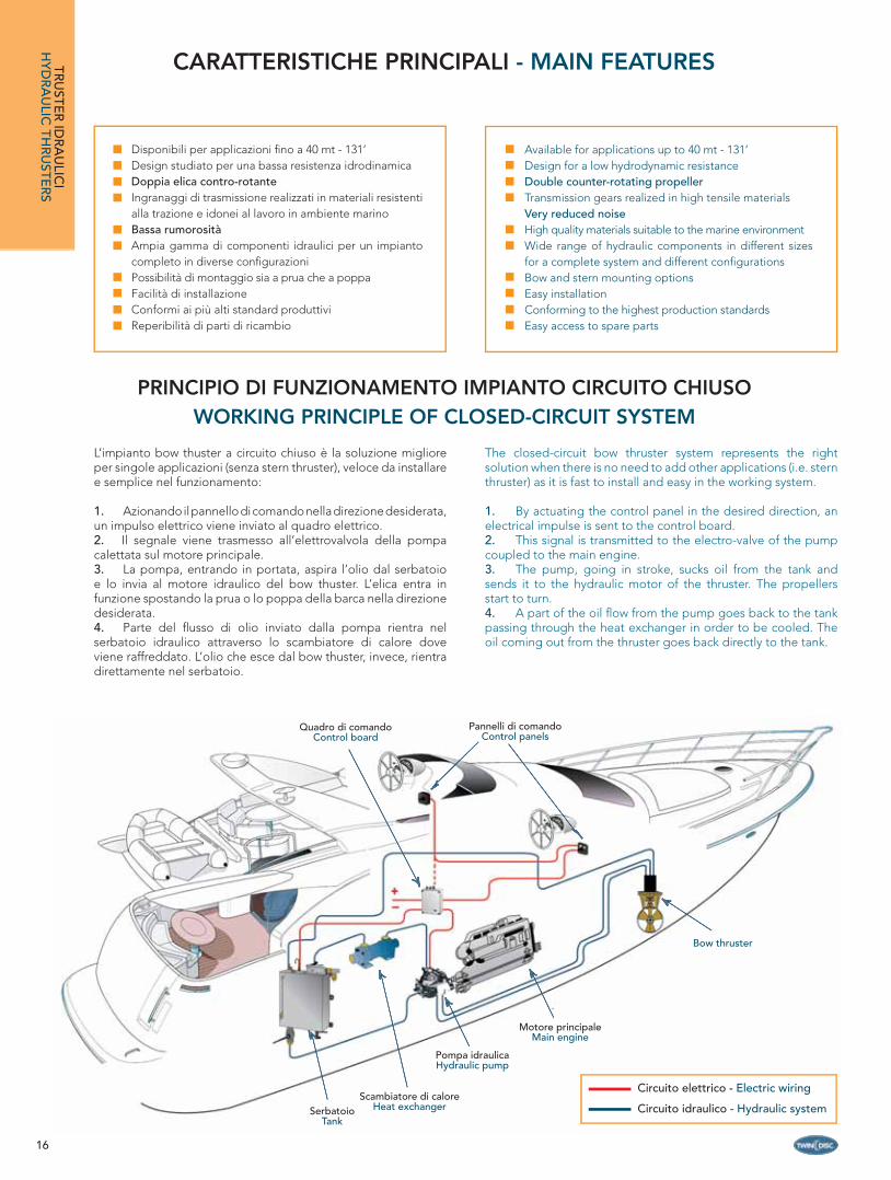
PRINCIPIO DI FUNZIONAMENTO IMPIANTO CIRCUITO CHIUSOWORKING PRINCIPLE OF CLOSED-CIRCUIT SYSTEM
The closed-circuit bow thruster system represents the right solution when there is no need to add other applications (i.e. stern thruster) as it is fast to install and easy in the working system.
1. By actuating the control panel in the desired direction, an electrical impulse is sent to the control board.2. This signal is transmitted to the electro-valve of the pump coupled to the main engine.3. The pump, going in stroke, sucks oil from the tank and sends it to the hydraulic motor of the thruster. The propellers start to turn.4. A part of the oil fl ow from the pump goes back to the tank passing through the heat exchanger in order to be cooled. The oil coming out from the thruster goes back directly to the tank.
L’impianto bow thuster a circuito chiuso è la soluzione migliore per singole applicazioni (senza stern thruster), veloce da installare e semplice nel funzionamento:
1. Azionando il pannello di comando nella direzione desiderata, un impulso elettrico viene inviato al quadro elettrico. 2. Il segnale viene trasmesso all’elettrovalvola della pompa calettata sul motore principale.3. La pompa, entrando in portata, aspira l’olio dal serbatoio e lo invia al motore idraulico del bow thuster. L’elica entra in funzione spostando la prua o lo poppa della barca nella direzione desiderata.4. Parte del fl usso di olio inviato dalla pompa rientra nel serbatoio idraulico attraverso lo scambiatore di calore dove viene raffreddato. L’olio che esce dal bow thuster, invece, rientra direttamente nel serbatoio.
TRU
STER
IDR
AU
LICI
HY
DR
AU
LIC TH
RU
STER
SC
Pannelli di comandoControl panels
Bow thruster
Motore principaleMain engine
Pompa idraulicaHydraulic pump
SerbatoioTank
Scambiatore di caloreHeat exchanger
Quadro di comandoControl board
Circuito elettrico - Electric wiring
Circuito idraulico - Hydraulic system
Disponibili per applicazioni fi no a 40 mt - 131’Design studiato per una bassa resistenza idrodinamicaDoppia elica contro-rotanteIngranaggi di trasmissione realizzati in materiali resistenti alla trazione e idonei al lavoro in ambiente marinoBassa rumorositàAmpia gamma di componenti idraulici per un impianto completo in diverse confi gurazioni Possibilità di montaggio sia a prua che a poppaFacilità di installazioneConformi ai più alti standard produttiviReperibilità di parti di ricambio
Available for applications up to 40 mt - 131’Design for a low hydrodynamic resistanceDouble counter-rotating propellerTransmission gears realized in high tensile materialsVery reduced noiseHigh quality materials suitable to the marine environmentWide range of hydraulic components in different sizes for a complete system and different confi gurations Bow and stern mounting optionsEasy installationConforming to the highest production standards Easy access to spare parts
17
All the BCS line hydraulic thrusters can be installed either in front or at rear of the boat, placed in any position, either vertically or horizontally: stern thruster is installed horizontally through the transom by means of a special resin tunnel fi xed to the boat itself.The stern tunnels are built in stainless steel and are available in two models for each diameter (please see the section “Accessories”
on page 22) having a different shape and length in order to offer the maximum fl exibility for the mounting on the transom and the minimum interference with other equipments on board.
MANOVRABILITÀ COMPLETA - COMPLETE MOVEMENT FREEDOM
Tutti i propulsori idraulici della linea BCS possono essere utilizzati sia a prua che a poppa, installati in qualsiasi posizione, sia verticale che orizzontale: a poppa vengono montati orizzontalmente, attraverso lo specchio posteriore, con l’ausilio di uno speciale tunnel. I tunnel per l’applicazione a poppa sono in acciaio inox, disponibili in due modelli per ogni diametro: variano nella forma e nella lunghezza (vedere la sezione “Accessori” a pag. 22) per garantire maggiore adattabilità allo specchio di poppa e minima interferenza con gli altri impianti di bordo.
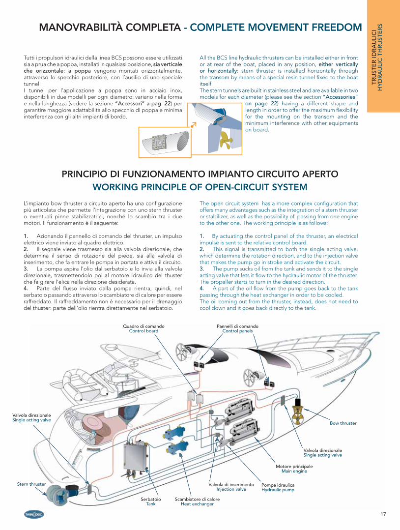
PRINCIPIO DI FUNZIONAMENTO IMPIANTO CIRCUITO APERTOWORKING PRINCIPLE OF OPEN-CIRCUIT SYSTEM
The open circuit system has a more complex confi guration that offers many advantages such as the integration of a stern thruster or stabilizer, as well as the possibility of passing from one engine to the other one. The working principle is as follows: 1. By actuating the control panel of the thruster, an electrical impulse is sent to the relative control board.2. This signal is transmitted to both the single acting valve, which determine the rotation direction, and to the injection valve that makes the pump go in stroke and activate the circuit.3. The pump sucks oil from the tank and sends it to the single acting valve that lets it fl ow to the hydraulic motor of the thruster. The propeller starts to turn in the desired direction.4. A part of the oil fl ow from the pump goes back to the tank passing through the heat exchanger in order to be cooled.The oil coming out from the thruster, instead, does not need to cool down and it goes back directly to the tank.
L’impianto bow thruster a circuito aperto ha una confi gurazione più articolata che permette l’integrazione con uno stern thruster o eventuali pinne stabilizzatrici, nonché lo scambio tra i due motori. Il funzionamento è il seguente:
1. Azionando il pannello di comando del thruster, un impulso elettrico viene inviato al quadro elettrico.2. Il segnale viene trasmesso sia alla valvola direzionale, che determina il senso di rotazione del piede, sia alla valvola di inserimento, che fa entrare le pompa in portata e attiva il circuito.3. La pompa aspira l’olio dal serbatoio e lo invia alla valvola direzionale, trasmettendolo poi al motore idraulico del thuster che fa girare l’elica nella direzione desiderata.4. Parte del fl usso inviato dalla pompa rientra, quindi, nel serbatoio passando attraverso lo scambiatore di calore per essere raffreddato. Il raffreddamento non è necessario per il drenaggio del thuster: parte dell’olio rientra direttamente nel serbatoio.
Pannelli di comandoControl panels
Bow thruster
Motore principaleMain engine
Pompa idraulicaHydraulic pump
SerbatoioTank
Scambiatore di caloreHeat exchanger
Quadro di comandoControl board
Valvola direzionaleSingle acting valve
Stern thruster
Valvola direzionaleSingle acting valve
Valvola di inserimentoInjection valve
TRU
STE
R ID
RA
ULI
CI
HY
DR
AU
LIC
TH
RU
STE
RS

18
Tutti i componenti idraulici ed elettrici necessari a completare l’impianto - pompe a pistoni, serbatoi, tunnel di prua e di poppa, scambiatore di calore, quadro elettrico e pannelli di comando - sono disponibili in vari modelli per diverse confi gurazioni e per soddisfare più applicazioni.Consultare la sezione ‘Accessori’ pag. 20-23. I propulsori idraulici della linea BCS hanno due eliche contro-rotanti e sono composti, nello schema base, come segue:
All the hydraulic components to complete the system, such as: pumps, tanks, tunnels, stern-thruster kits, heat exchanger, control board and control panels, are available in several models and sizes for a wide choice and confi guration possibilities to satisfy the most different applications.See the “Accessories” section on pages 20-23. The BCS hydraulic thrusters have two counter-rotating propellers. The basic composition is as follows:
COMPOSIZIONE IMPIANTO - SYSTEM COMPOSITIONTRU
STER
IDR
AU
LICI
HY
DR
AU
LIC TH
RU
STER
S
3
Il piede è in bronzo all’alluminio e ha un design affusolato per ridurre la resistenza idrodinamica e offrire maggiore effi cienza. I due anodi di zinco in corrispondenza delle ogive elica lo proteggono dalla corrosione elettrolitica. Gli ingranaggi interni di trasmissione sono realizzati in materiali altamente resistenti e trattati per durare a lungo anche in condizioni di lavoro continuo. Il loro design è stato oggetto particolare cura al fi ne di ridurre al minimo il livello di rumorosità su tutti i modelli.
The thruster leg is in bronze and has a special compact design to reduce the hydrodynamic resistance to a minimum and ensure a better effi ciency. It is provided with two zinc anodes on the propeller hubs for protection against electrolytic corrosion. All the transmissions gears inside the leg are realized in highly resistant materials and are appositely treated to provide a long life even under heavy-duty working conditions. Particular care was also given to their design, so as to considerably reduce the noise on all models.
1
Il motore idraulico a pistoni è idoneo a un uso continuo ed è disponibile in diverse cilindrate. Di ottima qualità e costruito in linea con i più alti standard produttivi, assicura massima effi cienza e lunga durata.
The hydraulic motor of the piston type is suitable for a continuous working and available in different displacements.It is of high quality materials and is built according to the highest production standards ensuring a high performance and a long trouble-free life.
4Le eliche sono realizzate in fusione di NiBrAl, una lega resistente allo sforzo e alla corrosione, particolarmente indicata nelle applicazioni in acqua marina. Le eliche contro-rotanti, ossia che girano in direzioni opposte, offrono una spinta più potente e omogenea in entrambe le direzioni.
The propellers are in NiBrAl, a special bronze alloy higly resistant to effort and corrosion, suitable to work in a marine environment. The two counter-rotating propellers, turning in opposite directions, achieve higher thrust and ensure an equal thrust in both directions.
2
La fl angia motore è montata direttamente sul piede (3) e ha la funzione di sorreggere il motore e fi ssarlo al tunnel. È costruita in una lega molto resistente e presenta una struttura robusta che garantisce la massima stabilità.
The motor fl ange is installed on the thruster leg (3) and has the function to support the motor itself and fi x it to the tunnel. It is built in a special alloy and has a strong structure to ensure the best stability.
19
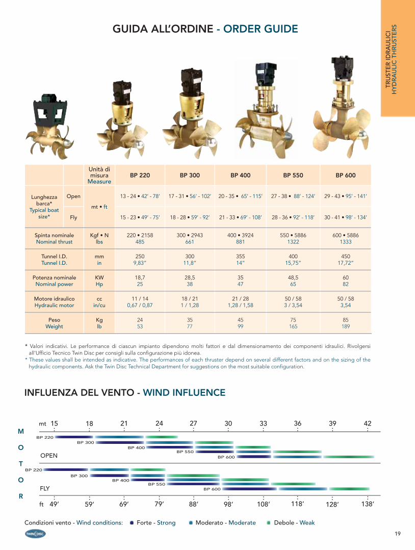
INFLUENZA DEL VENTO - WIND INFLUENCE
BP 220BP 300
BP 400BP 550
ft:
49’
OPEN
FLY
18:
21:
mt 15:
30:
33:
39:
42:M
O
T
O
R
Unità di misura
MeasureBP 220 BP 300 BP 400 BP 550 BP 600
Lunghezza barca*
Typical boat size*
Open
mt • ft
13 - 24 • 42’ - 78’ 17 - 31 • 56’ - 102’ 20 - 35 • 65’ - 115’ 27 - 38 • 88’ - 124’ 29 - 43 • 95’ - 141’
Fly 15 - 23 • 49’ - 75’ 18 - 28 • 59’ - 92’ 21 - 33 • 69’ - 108’ 28 - 36 • 92’ - 118’ 30 - 41 • 98’ - 134’
Spinta nominaleNominal thrust
Kgf • Nlbs
220 • 2158485
300 • 2943661
400 • 3924881
550 • 58861322
600 • 58861333
Tunnel I.D.Tunnel I.D.
mmin
2509,83”
30011,8”
35514”
40015,75”
45017,72”
Potenza nominaleNominal power
KWHp
18,725
28,538
3547
48,565
6082
Motore idraulicoHydraulic motor
ccin/cu
11 / 140,67 / 0,87
18 / 211 / 1,28
21 / 281,28 / 1,58
50 / 58 3 / 3,54
50 / 583,54
PesoWeight
Kglb
2453
3577
4599
75165
85189
* Valori indicativi. Le performance di ciascun impianto dipendono molti fattori e dal dimensionamento dei componenti idraulici. Rivolgersi all’Uffi cio Tecnico Twin Disc per consigli sulla confi gurazione più idonea.
* These values shall be intended as indicative. The performances of each thruster depend on several different factors and on the sizing of the hydraulic components. Ask the Twin Disc Technical Department for suggestions on the most suitable confi guration.
BP 600
GUIDA ALL’ORDINE - ORDER GUIDE
24:
27:
36:
BP 220
BP 300BP 400
BP 550BP 600
:59’
:69’
:79’
:88’
:98’
:108’
:118’
:128’
:138’
TRU
STE
R ID
RA
ULI
CI
HY
DR
AU
LIC
TH
RU
STE
RS
Condizioni vento - Wind conditions: Forte - Strong Debole - WeakModerato - Moderate

20
ACCESSORI - ACCESSORIES
Twin Disc offers two different types of control panels for thrusters:• the ON/OFF, for those who want to use their thrusters by just switching it on and perform the needed manoeuvres; this is also available with dual joystick in order to control both bow and stern thrusters.• the proportional speed panel for a total thrust control that can be increased or decreased by the operator depending on the pressure on the joystick. Its small dimensions allow a dual mounting confi guration either horizontally and vertically, in case of bow and stern thusters system.
MAIN FEATURES• Warning lights and acoustic alarm for temperature or oil level• Waterproof (IP65)• Power on/off • Compact design • Reduced dimensions for easy installation anywhere
Pannello di comando
Twin Disc offre due diversi tipi di pannelli di comando: • la versione ON/OFF per utilizzare il propulsore semplicemente azionando il pulsante di accensione ed effettuare le manovre necessarie. Disponibile anche nella versione con joystick doppio in caso di montaggio di stern thruster.• il tipo proporzionale ideale per un controllo totale della spinta, che può essere aumentata o diminuita direttamente dall’operatore attraverso la pressione esercitata sul joystick. Le dimensioni contenute ne permettono il montaggio doppio, sia in formazione affi ancata che sovrapposta, in caso di presenza di bow e stern thruster.
CARATTERISTICHE PRINCIPALI• Spie luminose e acustiche per temperatura e livello dell’olio• Resistente all’acqua (IP65)• Dispositivo di accensione e spegnimento• Design compatto• Dimensioni contenute per un facile posizionamento
Descrizione - Description CodiceCode
Pannello di comando proporzionale thruster per BP 220 - BP 300 - BP 400 - BP 550 - BP 600Single proportional control panel for thruster for BP 220 - BP 300 - BP 400 - BP 550 - BP 600
30043
Descrizione - Description Codice Code
Pannello di comando ON/OFF semplice thruster BP 220 - BP 300 - BP 400 - BP 550 - BP 600ON/OFF single control panel for bow thruster for BP 220 - BP 300 - BP 400 - BP 550 - BP 600
23530
Pannello di comando ON/OFF doppio thruster per BP 220 - BP 300 - BP 400 - BP 550 - BP 600ON/OFF double control panel for thrusters for BP 220 - BP 300 - BP 400 - BP 550 - BP 600
23531
PANNELLO ON/OFFON/OFF PANEL
PANNELLO PROPORZIONALEPROPORTIONAL PANEL
AC
CE
SSOR
IA
CC
ESSO
RIE
S Control panel
Codice - Code: 30043
21
Quadro elettrico
The control board contains the electric terminal block for the wiring of the system and the connection to the control panels. The control panel is provided with lights on the cover relating to the different functions.
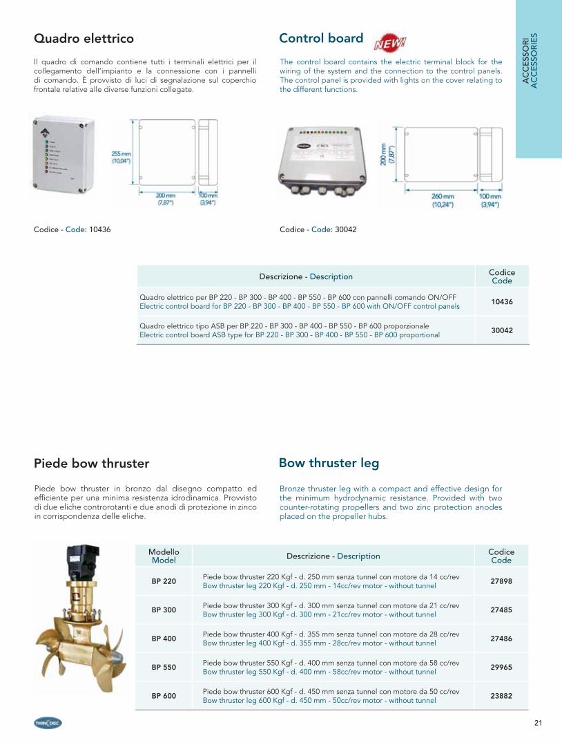
Il quadro di comando contiene tutti i terminali elettrici per il collegamento dell’impianto e la connessione con i pannelli di comando. È provvisto di luci di segnalazione sul coperchio frontale relative alle diverse funzioni collegate.
Descrizione - Description CodiceCode
Quadro elettrico per BP 220 - BP 300 - BP 400 - BP 550 - BP 600 con pannelli comando ON/OFFElectric control board for BP 220 - BP 300 - BP 400 - BP 550 - BP 600 with ON/OFF control panels 10436
Quadro elettrico tipo ASB per BP 220 - BP 300 - BP 400 - BP 550 - BP 600 proporzionaleElectric control board ASB type for BP 220 - BP 300 - BP 400 - BP 550 - BP 600 proportional 30042
ModelloModel Descrizione - Description Codice
Code
BP 220Piede bow thruster 220 Kgf - d. 250 mm senza tunnel con motore da 14 cc/revBow thruster leg 220 Kgf - d. 250 mm - 14cc/rev motor - without tunnel 27898
BP 300Piede bow thruster 300 Kgf - d. 300 mm senza tunnel con motore da 21 cc/revBow thruster leg 300 Kgf - d. 300 mm - 21cc/rev motor - without tunnel 27485
BP 400Piede bow thruster 400 Kgf - d. 355 mm senza tunnel con motore da 28 cc/revBow thruster leg 400 Kgf - d. 355 mm - 28cc/rev motor - without tunnel 27486
BP 550Piede bow thruster 550 Kgf - d. 400 mm senza tunnel con motore da 58 cc/revBow thruster leg 550 Kgf - d. 400 mm - 58cc/rev motor - without tunnel 29965
BP 600Piede bow thruster 600 Kgf - d. 450 mm senza tunnel con motore da 50 cc/revBow thruster leg 600 Kgf - d. 450 mm - 50cc/rev motor - without tunnel 23882
AC
CE
SSO
RI
AC
CE
SSO
RIE
SControl board
Bronze thruster leg with a compact and effective design for the minimum hydrodynamic resistance. Provided with two counter-rotating propellers and two zinc protection anodes placed on the propeller hubs.
Piede bow thruster in bronzo dal disegno compatto ed effi ciente per una minima resistenza idrodinamica. Provvisto di due eliche controrotanti e due anodi di protezione in zinco in corrispondenza delle eliche.
Piede bow thruster Bow thruster leg
Codice - Code: 30042Codice - Code: 10436
22
Descrizione - Description Codice Code
Tunnel stern thruster in acciao inox AISI316 - mod. S - d. 250 mm Stern thruster tunnel in AISI316 stainless steel - mod. S - d. 250 mm
per BP 220for BP 220 20694
Tunnel stern thruster in acciao inox AISI316 - mod. P - d. 250 mm Stern thruster tunnel in AISI316 stainless steel - mod. P - d. 250 mm
per BP 220 for BP 220 19977
Tunnel stern thruster in acciao inox AISI316 - mod. S - d. 300 mm Stern thruster tunnel in AISI316 stainless steel - mod. S - d. 300 mm
per BP 300for BP 300 30023
Tunnel stern thruster in acciao inox AISI316 - mod. P - d. 300 mm Stern thruster tunnel in AISI316 stainless steel - mod. P - d. 300 mm
per BP 300for BP 300 30027
Tunnel stern thruster in acciao inox AISI316 - mod. S - d. 355 mm Stern thruster tunnel in AISI316 stainless steel - mod. S - d. 355 mm
per BP 400for BP 400 27911
Tunnel stern thruster in acciao inox AISI316 - mod. P - d. 355 mm Stern thruster tunnel in AISI316 stainless steel - mod. P - d. 355 mm
per BP 400for BP 400 27909
Tunnel stern thruster in acciao inox AISI316 - mod. S - d. 400 mm Stern thruster tunnel in AISI316 stainless steel - mod. S - d. 400 mm
per BP 550for BP 550 30031
Tunnel stern thruster in acciao inox AISI316 - mod. P - d. 400 mm Stern thruster tunnel in AISI316 stainless steel - mod. P - d. 400 mm
per BP 550for BP 550 30028
Tunnel stern thruster in acciao inox AISI316 - mod. S - d. 450 mm Stern thruster tunnel in AISI316 stainless steel - mod. S - d. 450 mm
per BP 600for BP 600 23884
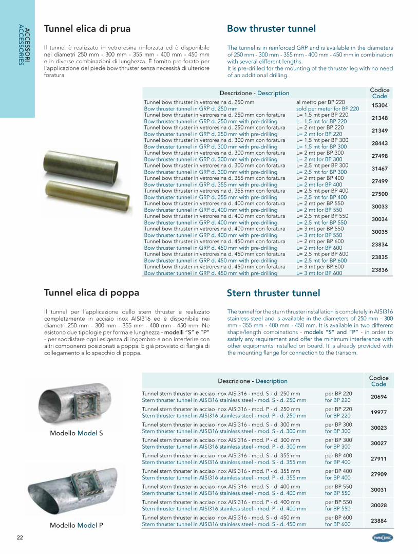
Tunnel elica di poppa
Il tunnel per l’applicazione dello stern thruster è realizzato completamente in acciaio inox AISI316 ed è disponibile nei diametri 250 mm - 300 mm - 355 mm - 400 mm - 450 mm. Ne esistono due tipologie per forma e lunghezza - modelli “S” e “P” - per soddisfare ogni esigenza di ingombro e non interferire con altri componenti posizionati a poppa. È già provvisto di fl angia di collegamento allo specchio di poppa.
The tunnel for the stern thruster installation is completely in AISI316 stainless steel and is available in the diameters of 250 mm - 300 mm - 355 mm - 400 mm - 450 mm. It is available in two different shape/length combinations - models “S” and “P” - in order to satisfy any requirement and offer the minimum interference with other equipments installed on board. It is already provided with the mounting fl ange for connection to the transom.
Modello Model P
Modello Model S
Tunnel elica di prua
Il tunnel è realizzato in vetroresina rinforzata ed è disponibile nei diametri 250 mm - 300 mm - 355 mm - 400 mm - 450 mm e in diverse combinazioni di lunghezza. È fornito pre-forato per l’applicazione del piede bow thruster senza necessità di ulteriore foratura.
Descrizione - Description Codice Code
Tunnel bow thruster in vetroresina d. 250 mmBow thruster tunnel in GRP d. 250 mm
al metro per BP 220sold per meter for BP 220 15304
Tunnel bow thruster in vetroresina d. 250 mm con foratura Bow thruster tunnel in GRP d. 250 mm with pre-drilling
L= 1,5 mt per BP 220L= 1,5 mt for BP 220 21348
Tunnel bow thruster in vetroresina d. 250 mm con foratura Bow thruster tunnel in GRP d. 250 mm with pre-drilling
L= 2 mt per BP 220L= 2 mt for BP 220 21349
Tunnel bow thruster in vetroresina d. 300 mm con foratura Bow thruster tunnel in GRP d. 300 mm with pre-drilling
L= 1,5 mt per BP 300L= 1,5 mt for BP 300 28443
Tunnel bow thruster in vetroresina d. 300 mm con foratura Bow thruster tunnel in GRP d. 300 mm with pre-drilling
L= 2 mt per BP 300 L= 2 mt for BP 300 27498
Tunnel bow thruster in vetroresina d. 300 mm con foratura Bow thruster tunnel in GRP d. 300 mm with pre-drilling
L= 2,5 mt per BP 300 L= 2,5 mt for BP 300 31467
Tunnel bow thruster in vetroresina d. 355 mm con foratura Bow thruster tunnel in GRP d. 355 mm with pre-drilling
L= 2 mt per BP 400 L= 2 mt for BP 400 27499
Tunnel bow thruster in vetroresina d. 355 mm con foratura Bow thruster tunnel in GRP d. 355 mm with pre-drilling
L= 2,5 mt per BP 400 L= 2,5 mt for BP 400 27500
Tunnel bow thruster in vetroresina d. 400 mm con foratura Bow thruster tunnel in GRP d. 400 mm with pre-drilling
L= 2 mt per BP 550L= 2 mt for BP 550 30033
Tunnel bow thruster in vetroresina d. 400 mm con foratura Bow thruster tunnel in GRP d. 400 mm with pre-drilling
L= 2,5 mt per BP 550L= 2,5 mt for BP 550 30034
Tunnel bow thruster in vetroresina d. 400 mm con foratura Bow thruster tunnel in GRP d. 400 mm with pre-drilling
L= 3 mt per BP 550L= 3 mt for BP 550 30035
Tunnel bow thruster in vetroresina d. 450 mm con foratura Bow thruster tunnel in GRP d. 450 mm with pre-drilling
L= 2 mt per BP 600L= 2 mt for BP 600 23834
Tunnel bow thruster in vetroresina d. 450 mm con foratura Bow thruster tunnel in GRP d. 450 mm with pre-drilling
L= 2,5 mt per BP 600L= 2,5 mt for BP 600 23835
Tunnel bow thruster in vetroresina d. 450 mm con foratura Bow thruster tunnel in GRP d. 450 mm with pre-drilling
L= 3 mt per BP 600L= 3 mt for BP 600 23836
The tunnel is in reinforced GRP and is available in the diameters of 250 mm - 300 mm - 355 mm - 400 mm - 450 mm in combination with several different lengths.It is pre-drilled for the mounting of the thruster leg with no need of an additional drilling.
AC
CE
SSOR
IA
CC
ESSO
RIE
S
Bow thruster tunnel
Stern thruster tunnel
23
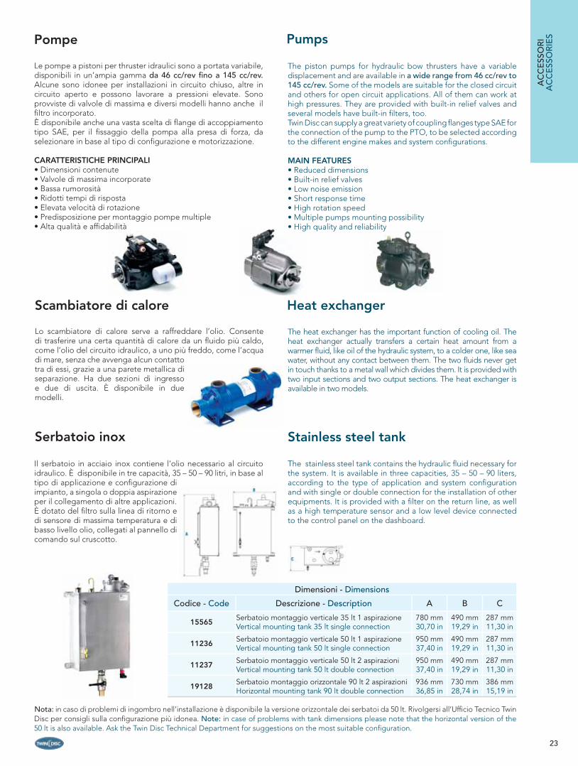
Il serbatoio in acciaio inox contiene l’olio necessario al circuito idraulico. È disponibile in tre capacità, 35 – 50 – 90 litri, in base al tipo di applicazione e confi gurazione di impianto, a singola o doppia aspirazione per il collegamento di altre applicazioni.È dotato del fi ltro sulla linea di ritorno e di sensore di massima temperatura e di basso livello olio, collegati al pannello di comando sul cruscotto.
Serbatoio inox
The stainless steel tank contains the hydraulic fl uid necessary for the system. It is available in three capacities, 35 – 50 – 90 liters, according to the type of application and system confi guration and with single or double connection for the installation of other equipments. It is provided with a fi lter on the return line, as well as a high temperature sensor and a low level device connected to the control panel on the dashboard.
Pompe
Le pompe a pistoni per thruster idraulici sono a portata variabile, disponibili in un’ampia gamma da 46 cc/rev fi no a 145 cc/rev. Alcune sono idonee per installazioni in circuito chiuso, altre in circuito aperto e possono lavorare a pressioni elevate. Sono provviste di valvole di massima e diversi modelli hanno anche il fi ltro incorporato. È disponibile anche una vasta scelta di fl ange di accoppiamento tipo SAE, per il fi ssaggio della pompa alla presa di forza, da selezionare in base al tipo di confi gurazione e motorizzazione.
CARATTERISTICHE PRINCIPALI• Dimensioni contenute• Valvole di massima incorporate• Bassa rumorosità• Ridotti tempi di risposta• Elevata velocità di rotazione• Predisposizione per montaggio pompe multiple• Alta qualità e affi dabilità
Scambiatore di calore
Lo scambiatore di calore serve a raffreddare l’olio. Consente di trasferire una certa quantità di calore da un fl uido più caldo, come l’olio del circuito idraulico, a uno più freddo, come l’acqua di mare, senza che avvenga alcun contatto tra di essi, grazie a una parete metallica di separazione. Ha due sezioni di ingresso e due di uscita. È disponibile in due modelli.
The heat exchanger has the important function of cooling oil. The heat exchanger actually transfers a certain heat amount from a warmer fl uid, like oil of the hydraulic system, to a colder one, like sea water, without any contact between them. The two fl uids never get in touch thanks to a metal wall which divides them. It is provided with two input sections and two output sections. The heat exchanger is available in two models.
AC
CE
SSO
RI
AC
CE
SSO
RIE
SPumps
Heat exchanger
Stainless steel tank
Nota: in caso di problemi di ingombro nell’installazione è disponibile la versione orizzontale dei serbatoi da 50 lt. Rivolgersi all’Uffi cio Tecnico Twin Disc per consigli sulla confi gurazione più idonea. Note: in case of problems with tank dimensions please note that the horizontal version of the 50 lt is also available. Ask the Twin Disc Technical Department for suggestions on the most suitable confi guration.
Dimensioni - Dimensions
Codice - Code Descrizione - Description A B C
15565Serbatoio montaggio verticale 35 lt 1 aspirazioneVertical mounting tank 35 lt single connection
780 mm 30,70 in
490 mm 19,29 in
287 mm 11,30 in
11236Serbatoio montaggio verticale 50 lt 1 aspirazioneVertical mounting tank 50 lt single connection
950 mm 37,40 in
490 mm 19,29 in
287 mm 11,30 in
11237Serbatoio montaggio verticale 50 lt 2 aspirazioniVertical mounting tank 50 lt double connection
950 mm 37,40 in
490 mm 19,29 in
287 mm 11,30 in
19128Serbatoio montaggio orizzontale 90 lt 2 aspirazioniHorizontal mounting tank 90 lt double connection
936 mm 36,85 in
730 mm 28,74 in
386 mm 15,19 in
The piston pumps for hydraulic bow thrusters have a variable displacement and are available in a wide range from 46 cc/rev to 145 cc/rev. Some of the models are suitable for the closed circuit and others for open circuit applications. All of them can work at high pressures. They are provided with built-in relief valves and several models have built-in fi lters, too.Twin Disc can supply a great variety of coupling fl anges type SAE for the connection of the pump to the PTO, to be selected according to the different engine makes and system confi gurations.
MAIN FEATURES• Reduced dimensions• Built-in relief valves• Low noise emission• Short response time• High rotation speed• Multiple pumps mounting possibility• High quality and reliability
24
PARTI DI RICAMBIO - SPARE PARTSTHRUSTER ELETTRICI - ELECTRIC THRUSTERS
PosizionePosition
DescrizioneDescription
CodiceCode
1
Anodo bow thruster per bt 35 - Bow thruster zinc anode for BT 35 21419
Anodo bow thruster per BT 55 - BT 85 - BT 100 - BT 120Bow thruster zinc anode for BT 55 - BT 85 - BT 100 - BT 120 12120
Anodo bow thruster per BT 160 - bow thruster zinc anode for BT 160 12116
2
Kit elica 4 pale d.123 mm completa per bt 35Complete kit of four-blades propeller d.123 mm for bt 35 23649
Elica d. 123 per BT 35 - Propeller d. 123 mm for BT 35 21443
Kit elica 3 pale d. 180 mm completa per BT 55 - BT 85 - BT 100 - BT 120Complete kit of three-blades propeller d.180 mm for BT 55 - BT 85 - BT 100 - BT 120 16216
Elica 3 pale d. 180 mm - per BT 55 - BT 85 - BT 100 - BT 120Three-blades propeller d.180 mm - for BT 55 - BT 85 - BT 100 - BT 120 16200
Elica 3 pale 245x350 mm per BT 160Three-blades propeller 245x350 mm for BT 160 16319
Coperchio fi ssaggio elica (metà) per BT 55 - BT 85 - BT 100 - BT 120 Half propeller cover for BT 55 - BT 85 - BT 100 - BT 120 16201
3
Spina fi ssaggio elica d. 4 - 23 mm per BT 35 Propeller fi xing pin d. 4 - 23 mm for BT 35 21447
Spina elica d. 5 - 27.5 mm per BT 55 - BT 85 - BT 100 - BT 120Propeller pin d. 5 - 27.5 mm for BT 55 - BT 85 - BT 100 - BT 120 16202
4Fascetta in plastica a dentini 15 - 17.2 Per tenuta spina per BT 85 - BT 100 - BT 120Plastic teeth strip for pin fi xing 15-17.2 for BT 85 - BT 100 - BT 120 16253
5
Piede bow thruster 35kgf - d. 125 mm per BT 35Bow thruster leg 35kgf - d. 125 mm for BT 35 21412
Piede bow thruster 55kgf - d. 185 mm - per BT 55 12/24VBow thruster leg 55kgf - d. 185 mm - for BT 55 12/24V 16215
Piede bow thruster 85kgf - d. 185 mm - per BT 85 12/24VBow thruster leg 85kgf - d. 185 mm - for BT 85 12/24V 10412
Piede bow thruster 100kgf - d. 185 mm - per BT 100 12/24VBow thruster leg 100kgf - d. 185 mm - for BT 100 12/24V 24020
Piede bow thruster 120kgf - d. 185 mm - per BT 120Bow thruster leg 120kgf - d. 185 mm - for BT 120 22811
Piede bow thruster 160kgf - d. 250 mm - per BT 160Bow thruster leg 160kgf - d. 250 mm - for BT 160 23223
6
Giunto collegamento motore bow thruster per BT 55Motor coupling for bow thruster mod. BT 55 12127
Giunto collegamento motore bow thruster per BT 85 - BT 100 - BT 120Motor coupling for bow thruster mod. BT 85 - BT 100 - BT 120 10417
Giunto elastico per BT 160 - elastic coupling for BT 160 16320
7
Spina giunto d. 4 X 20 per BT 35 - Shear pin d.4X20 for BT 35 23607
Spina giunto d. 3 - 23.3 mm per BT 55 - shear pin d. 3 - 23.3 mm for BT 55 16208
Spina giunto per BT 85 - BT 100 - BT 120 - shear pin for BT 85 - BT 100 - BT 120 16255
8
Kit di ingrassaggio piede bow thruster per BT 35Leg lubricating kit for BT 35 21466
Kit di ingrassaggio piede bow thruster per BT 55 - BT 85 - BT 100 - BT 120 - BT 160Leg lubricating kit for BT 55 - BT 85 - BT 100 - BT 120 - BT 160 10393
9Olio tipo hd 80W/90 - tanica da 250 ml per kit ingrassaggio piede bow thrusterHydraulic oil type hd 80W/90 - for leg lubricating kit - bottle of 250 ml 15729
10
Motore 2200W - 12V per BT 35 - Electric motor 2200W - 12V for BT 35 21442
Motore 3000W - 24V per BT 55 - Electric motor 3000W - 24V for BT 55 11546
Motore 3000W - 12V per BT 55 - Electric motor 3000W - 24V for BT 55 16214
PARTI D
I RIC
AM
BIO
SPAR
E PA
RTS
2
13
5
3 - 41
8
6
7
121110
9
14
25
PosizionePosition
DescrizioneDescription
CodiceCode
10
Motore 4800W - 24V per BT 85 - Electric motor 4800W - 24V for BT 85 16257
Motore 5300W- 12V per BT 85 - Electric motor 5300W - 24V for BT 85 16256
Motore 6000W - 12V per BT 100 - Electric motor 6000W - 24V for BT 100 22801
Motore 6000W - 24V per BT 100 - Electric motor 6000W - 24V for BT 100 22802
Motore 8000W - 24V per BT 120 - BT 160Electric motor 8000W - 24V for BT 120 - BT 160 22803
Cavo collegamento elettrico per BT 35 - BT 55 - BT 85 - BT 100 - BT 120 - BT 160Electric cable connection for motor BT 35 - BT 55 - BT 85 - BT 100 - BT 120 - BT 160 16262
11
Kit N. 4 spazzole 9x13x23,5 motore 2,2KW 12V per BT 35Kit of N. 4 brushes 9x13x23,5 for motor of 2,2KW 12V for BT 35 23718
Kit N. 4 spazzole 9,2x20x27,7 motore 3KW 12/24V per BT 55Kit of N. 4 brushes 9,2x20x27,7 for motor of 3KW 12/24V for BT 55 23716
Kit N. 4 spazzole 12,5x48x32 motore 5,3KW 12V e 4,8KW 24V per BT 85Kit of N. 4 brushes 12,5x48x32 for motor of 5,3KW 12V and 4,8KW 24V for BT 85 11282
Kit N. 4 spazzole 12,5x48x32 motore 6KW 12 e 24V per BT 100Kit of N. 4 brushes 12,5x48x32 for motor of 6KW 12V and 24V for BT 100 23717
Kit N. 4 spazzole 12,5x48x32 motore 8KW 24V per BT 120 - BT 160Kit of N. 4 brushes 12,5x48x32 for motor of 8KW 24V for BT 120 - BT 160 23715
12
Relé 12V per BT 35 - Relay 12V for BT 35 21435
Relé 12V per BT 55 - Relay 12V for BT 55 16210
Relé 12V per BT 85 - Relay 12V for BT 85 12131
Relé 24V per BT 85 - BT 55 - Relay 24V for BT 55 - BT 85 16270
Relé 12V per BT 100 - Relay 12V for BT 100 22805
Relé 24V per BT 100 - Relay 24V for BT 100 22806
Relé 24V per BT 120 E BT 160 - Relay 24V for BT 120 - BT 160 22804
13
Carter nero per BT 35 12V - Black cover for BT 35 12V 21440
Carter nero per BT 55 12/24V - Black cover for BT 55 12/24V 22366
Carter nero per BT 85 12/24V - Black cover for BT 85 12/24V 22370
Carter nero per BT 100 12V - Black cover for BT 100 12V 24812
Carter nero per BT 100 24V - Black cover for BT 100 24V 23068
Carter nero per BT 120 24V - Black cover for BT 120 24V 23069
Carter nero per BT 160 24V - Black cover for BT 160 24V 23070
14Elettronica di controllo 12/24V per BT 35 - BT 55 - BT 85 - BT 100 - BT 120 - BT 160Electronic control box 12/24V for BT 35 - BT 55 - BT 85 - BT 100 - BT 120 - BT 160 25515
Kit parti di ricambio BT 35 con elettronica - Spare parts kit for BT 35 with electronic device 25666
Kit parti di ricambio BT 55 con elettronica - Spare parts kit for BT 55 with electronic device 25667
Kit parti di ricambio BT 85 con elettronica - Spare parts kit for BT 85 with electronic device 25668
Kit parti di ricambio BT 100 con elettronica - Spare parts kit for BT 100 with electronic device 25669
Kit parti di ricambio BT 120 con elettronica - Spare parts kit for BT 120 with electronic device 25670
Kit parti di ricambio BT 160 con elettronica - Spare parts kit for BT 160 with electronic device 25671
2
13
5
3 - 41
8
6
7
121110
9
14
PART
I DI R
ICA
MB
IOSP
AR
E P
ART
S

26
PARTI DI RICAMBIO - SPARE PARTSTHRUSTER IDRAULICI - HYDRAULIC THRUSTERS
PosizionePosition
DescrizioneDescription
CodiceCode
1
Ogiva bow thruster con anodo in zinco per BP 220 – Zinc protection anode for BP 220 27893Ogiva bow thruster con anodo in zinco per BP 300 - BP 400 Zinc protection anode for BP 300 - BP 400 10363
Ogiva bow thruster con anodo in zinco per BP 550 – Zinc protection anode for BP 550 29987Ogiva bow thruster con anodo in zinco per BP 600 – Zinc protection anode for BP 600 18139
2
Elica destra d. 245 mm in NiBrAl cinque pale per BP 220 Five-blades propeller in NiBrAl d. 245 mm for BP 220 - right 27884
Elica sinistra d. 245 mm in NiBrAl cinque pale per BP 220 Five-blades propeller in NiBrAl d. 245 mm for BP 220 - left 27886
Elica destra d. 290 mm in NiBrAl quattro pale per BP 300 Four-blades propeller in NiBrAl d. 290 mm for BP 300 - right 27445
Elica sinistra d. 290 mm in NiBrAl quattro pale per BP 300 Four-blades propeller in NiBrAl d. 290 mm for BP 300 - left 27446
Elica destra d. 345 mm in NiBrAl quattro pale per BP 400 Four-blades propeller in NiBrAl d. 345 mm for BP 400 - right 27060
Elica sinistra d. 345 mm in NiBrAl quattro pale per BP 400 Four-blades propeller in NiBrAl d. 345 mm for BP 400 - left 27061
Elica destra d. 395 mm in NiBrAl cinque pale per BP 550 Five-blades propeller in NiBrAl d. 395 mm for BP 550 - right 29982
Elica sinistra d. 395 mm in NiBrAl cinque pale per BP 550 Five-blades propeller in NiBrAl d. 395 mm for BP 550 - left 29984
Elica destra d. 430 mm in NiBrAl quattro pale per BP 600 Four-blades propeller in NiBrAl d. 430 mm for BP 600 - right 18989
Elica sinistra d. 430 mm in NiBrAl quattro pale per BP 600 Four-blades propeller in NiBrAl d. 430 mm for BP 600 - left 18990
3
Piede bow thruster senza motore per BP 220 – Bow thruster leg no motor for BP 220 27892
Piede bow thruster senza motore per BP 300 – Bow thruster leg no motor for BP 300 27480
Piede bow thruster senza motore per BP 400 – Bow thruster leg no motor for BP 400 27481
Piede bow thruster senza motore per BP 550 – Bow thruster leg no motor for BP 550 29966
Piede bow thruster senza motore per BP 600 – Bow thruster leg no motor for BP 600 22417
4
Supporto motore bow thruster per BP 220 – Bow thruster motor support for BP 220 10416
Supporto motore bow thruster per BP 300 – Bow thruster motor support for BP 300 27451
Supporto motore bow thruster per BP 400 – Bow thruster motor support for BP 400 27456Supporto motore bow thruster per BP 550 e BP 600Bow thruster motor support for BP 550 and BP 600 22364
5
Motore idraulico a ingranaggi per BP 220 – Hydraulic gear motor for BP 220 27860Motore idraulico a pistoni 21 cc/rev per BP 300 - Hydraulic gear motor 21 cc/rev for BP 300 13776Motore idraulico a pistoni 28 cc/rev per BP 400 - Hydraulic gear motor 28 cc/rev for BP 400 13778Motore idraulico a pistoni 58 cc/rev per BP 550 e BP 600 Hydraulic gear motor 58 cc/rev for BP 550 and BP 600 22421
Motore idraulico a pistoni 50 cc/rev per BP 600 - Hydraulic gear motor 50 cc/rev for BP 600 23886
6
Giunto elastico per motore bow thruster BP 220 Elastic motor coupling for bow thruster BP 220 27896
Giunto superiore accoppiamento motore bow thruster per BP 300 - BP 400Upper motor coupling for bow thruster BP 300 - BP 400 10418
Giunto inferiore accoppiamento motore bow thruster per BP 300 - BP 400Lower motor coupling for bow thruster BP 300 - BP 400 10372
Elemento elastico per giunto bow thruster per BP 300 - BP 400Elastic component for bow thruster coupling for BP 300 - BP 400 11815
Giunto inferiore accoppiamento motore bow thruster per BP 550 - BP 600Lower motor coupling for bow thruster mod. BP 550 - BP 600 18949
Giunto superiore accoppiamento motore bow thruster per BP 550 - BP 600Upper motor coupling for bow thruster mod. BP 550 - BP 600 22412
Elemento elastico per giunto bow thruster per BP 550 - BP 600Elastic component for bow thruster coupling for P 550 - BP 600 19007
7
Kit guarnizioni piede per BP 220 – Leg seal kit for BP 220 30009
Kit guarnizioni piede per BP 300 - BP 400 – Leg seal kit for BP 300 - BP 400 18950
Kit guarnizioni piede per BP 550 – Leg seal kit for BP 550 30014
Kit guarnizioni piede per BP 600 – Leg seal kit for BP 600 23885
8Kit di ingrassaggio piede bow thruster per BP 220 - BP 300 - BP 400 - BP 550 - BP 600Leg lubricating kit for BP 220 - BP 300 - BP 400 - BP 550 - BP 600 10393
9Olio tipo HD 80W/90 - tanica da 250 ml per kit ingrassaggio piede bow thrusterHydraulic oil type HD 80W/90 - for leg lubricating kit - bottle of 250 ml
15729
2
4
5
6
1
3
8
9
7PA
RTI DI R
ICA
MB
IOSPA
RE
PARTS

27
ModelloModel BT 35 BT 55 BT 85 BT 100 BT 120 BT 160
A (mm • in) 125 • 4,92” 185 • 7,28” 185 • 7,28” 185 • 7,28” 185 • 7,28” 250 • 9,83”
B (mm • in) 218 • 8,58” 280 • 11,02” 340 • 13,38” 352 • 13,86” 425 • 16,73” 475 • 18,70”
C (mm • in)minimo - minimum 125 • 4,92” 185 • 7,28” 185 • 7,28” 185 • 7,28” 185 • 7,28” 250 • 9,83”
D (mm • in) 250 – 5009,83” – 19,68”
370 – 74014,57” – 29,13”
370 – 740 14,57” – 29,13”
370 – 74014,57” – 29,13”
370 – 74014,57” – 29,13”
500 – 100019,68” – 39,37”
E (mm • in) 4 • 0,16” 5 • 0,20” 5 • 0,20” 5 • 0,20” 5 • 0,20” 0,20” 7 • 0,28”
F (mm • in) 135 • 5,31” 150 • 5,90” 175 • 6,89” 175 • 6,89” 160 • 6,30” 160 • 6,30”
G (mm • in) 50 • 1,97” 70 • 2,76” 70 • 2,76” 70 • 2,76” 70 • 2,76” 105 • 4,13”
H (mm • in)minimo - minimum 500 • 19,68” 500 • 19,68” 500 • 19,68” 500 • 19,68” 500 • 19,68” 500 • 19,68”
Specifi che tecniche - Technical details
SpintaThrust
(kg • lbs • N)35 • 78 • 343 55 • 122 • 540 85 • 188 • 834 100 • 220 • 981 120 • 265 • 1177 160 • 353 • 1570
Potenza Power (Kw • Hp) 2,2 • 3 3 • 4
5,3 • 7,1 (12V) 4,8 • 6,4 (24V)
6 • 8 8 • 10,7 8 • 10,7
VoltaggioVoltage (V) 12 12 • 24 12 • 24 12 • 24 24 24
Peso Weight (Kg • lb) 10,5 • 23,5 20 • 44 25 • 55,1 26 • 57,3 45 • 99 52 • 114,6
H
C
A
DIMENSIONI E SPECIFICHE TECNICHEDIMENSIONS AND TECHNICAL SPECIFICATIONS
THRUSTER ELETTRICI - ELECTRIC THRUSTERS
SPE
CIF
ICH
E T
EC
NIC
HE
TEC
HN
ICA
L SP
EC
IFIC
ATI
ON
S

28
DIMENSIONI E SPECIFICHE TECNICHEDIMENSIONS AND TECHNICAL SPECIFICATIONS
THRUSTER IDRAULICI - HYDRAULIC THRUSTERS
Modello - Model BP 220 BP 300 BP 400 BP 550 BP 600
A (mm • in) 250 • 9,83” 300 • 11,8” 355 • 14” 400 • 15,75” 450 • 17,72”
C (mm • in) 352 • 13,8” 465 • 18,30” 495 • 19,5” 600 • 23,6” 625 • 24,61”
D (mm • in)minimo - minimum 250 • 9,83” 300 • 11,81” 360 • 14,17” 400 • 15,75” 450 • 17,72”
E (mm • in) 500 - 100019,68” - 39,37”
580 - 116022,83” - 45,6”
700 - 136027,56” - 53,54”
800 - 160031,5”- 63”
800 - 160031,5”- 63”
F (mm • in) 348 • 13,7” 425• 16,73” 425• 16,73” 498 • 19,6” 508 • 20,00”
H (mm • in)minimo - minimum 500 • 19,68” 500 • 19,68” 500 • 19,68” 500 • 19,68” 500 • 19,68”
Specifi che tecniche - Technical details
SpintaThrust
(kg • lbs • N)220 • 485 • 2158 300 • 661 • 2943 400 • 881 • 3924 550 • 1322
5886600 • 1333
5886
Potenza Power (Kw • Hp) 18,7 • 25 28,5 • 38 35 • 47 48,5 • 65 60 • 82
Peso Weight (Kg•lb) 24 • 53 35 • 77 45 • 99 75 • 165 85 • 189
Lunghezza standard tunnel
Standard length of tunnel
(mm • in)
1500 - 200078,74”
1500 - 2000 78,74”
2000 - 250078,74” - 98,42”
2000 - 25003000
78,74” - 98,42” 118,11”
2000 - 25003000
78,74” - 98,42” 118,11”
E
A
CD
F
H
SPEC
IFICH
E TE
CN
ICH
ETE
CH
NIC
AL SPE
CIFIC
ATIO
NS
29
DIMENSIONI TUNNEL STERN THRUSTERDIMENSIONS OF STERN THRUSTER TUNNELS
ModelloModel BP 220/S BP 220/P BP 300/S BP 300/P BP 400/S BP 400/P BP 550/S BP 550/P BP 600/S
A (mm • ft) 250 • 9,83” 250 • 9,83” 300 • 11,81” 300 • 11,81” 355 • 13,98” 355 • 13,98” 400 • 15,75” 400 • 15,75” 450 • 17,72”
B (mm • ft) 162 • 6,38” 162 • 6,38” 187 • 7,36” 187 • 7,36” 214,5 • 8,44”
214,5 • 8,44” 239 • 9,41” 239 • 9,41” 264 • 10,39”
C (mm • ft) 80 • 3,15” 80 • 3,15” 80 • 3,15” 80 • 3,15” 80 • 3,15” 80 • 3,15” 80 • 3,15” 80 • 3,15” 80 • 3,15”
D (mm • ft) 345 • 13,58” 345 • 13,58” 270 • 10,63” 270 • 10,63” 270 • 10,63” 270 • 10,63” 350 • 13,78” 350 • 13,78” 350 • 13,78”
E (mm • ft) 345 • 13,58” 345 • 13,58” 250 • 9,83” 250 • 9,83” 250 • 9,83” 250 • 9,83” 350 • 13,78” 350 • 13,78” 350 • 13,78”
F (mm • ft) 250 • 9,83” 250 • 9,83” 165 • 6,50” 165 • 6,50” 165 • 6,50” 165 • 6,50” 250 • 9,83” 250 • 9,83” 250 • 9,83”
G (mm • ft) 250 • 9,83” 250 • 9,83” 150 • 5,91” 150 • 5,91” 150 • 5,91” 150 • 5,91” 250 • 9,83” 250 • 9,83” 250 • 9,83”
H (mm • ft) 390 • 15,35” 390 • 15,35” 465 • 18,31” 465 • 18,31” 492,5 • 18,70” 492,5 • 19,39” 600 • 23,62” 600 • 23,62” 625 • 24,61”
L (mm • ft) 500 • 19,68” 500 • 19,68” 600 • 23,62” 550 • 21,65” 700 • 27,56” 700 • 27,56” 700 • 27,56” 700 • 27,56” 1000 • 39,37”
L1 (mm • ft) - 850 • 33,46” - 950 • 37,4” - 1000 • 39,37” - 1000 • 39,37” -
G
L1D
FL
E
A
B CH
MODEL “P”
D
LF
GE
HB C
A
MODEL “S”
SPE
CIF
ICH
E T
EC
NIC
HE
TEC
HN
ICA
L SP
EC
IFIC
ATI
ON
S

30
Twin Disc garantisce che i prodotti venduti sono privi di qualsiasi difetto di fabbricazione o di altro difetto risultante da progettazione, materie prime o costruzione, nei termini e nei limiti indicati di seguito:1) Periodo di validità della garanzia1.a. Il periodo di garanzia è di ventiquattro (24) mesi a partire dalla data del primo utilizzo da parte dell’utente originale oppure trenta (30) mesi dalla data di consegna dei prodotti al trasportatore, distributore o rivenditore. Qualora i nostri impianti siano montati o utilizzati su barche da lavoro o di tipo commerciale, il periodo di garanzia è di dodici (12) mesi dalla data di produzione. Il produttore ha il diritto di richiedere al cliente prova della data di commissione specificata sulla richiesta di garanzia.1.b. Questo periodo non può essere esteso e neppure interrotto per vie legali o amichevoli da parte del cliente. Al termine di questo periodo la garanzia si ritiene conclusa senza ulteriori considerazioni.1.c. La garanzia non sarà rinnovata a seguito di riparazioni sostituzioni o qualora il prodotto venga rivenduto.2) Condizioni in cui decade la garanzia2.a. L’obbligazione di garanzia non viene applicata in caso di negligenza, cattiva manutenzione o supervisione, responsabilità dell’operatore, imprudenza, non osservanza delle istruzioni di funzionamento raccomandate, cause di forza maggiore o utilizzo di olio di scarsa qualità per l’impianto. Il produttore è sollevato da qualsiasi responsabilità in caso di danno causato da perdite di olio o trafilamenti.2.b. La garanzia non viene inoltre applicata in caso di incidenti dovuti a cause di forza maggiore, così come qualsiasi danno, sostituzione o riparazione che eccede la normale usura.2.c. La garanzia decade qualora i nostri articoli siano installati su unità di comando unitamente a prodotti forniti da altri produttori.2.d. La garanzia non è applicabile qualora l’impianto non sia ritornato al produttore nelle condizioni in cui si trovava al momento del difetto stesso o qualora sia stato precedentemente smontato, riparato, modificato da una terza parte, dall’utilizzatore oppure dal cliente.2.e. La garanzia non copre difetti derivati da costruzioni o scelte di materiale non adatto se il cliente ha ordinato la realizzazione del prodotto con tali caratteristiche, nonostante il preavviso di Twin Disc.3) Modalità di intervento3.a. In caso di malfunzionamento dell’impianto durante il periodo di garanzia, il produttore, centro di assistenza o distributore, deve essere contattato per autorizzare qualsiasi tipo di lavoro. Il cliente deve fare tutto il possibile per far sì che l’assistente sia in grado di accertare tali difetti ed effettuare azioni correttive. Una volta ricevuto debita notifica del difetto, l’assistente deve correggere tale difetto nel minor tempo possibile, riservandosi il diritto, qualora possibile, di modificare tutto o parte dell’impianto al fine di adempiere alle obbligazioni.3.b. La riparazione o la sostituzione del prodotto in garanzia o del componente difettoso sarà a giudizio del nostro ufficio tecnico; la garanzia è limitata alla riparazione nell’officina del produttore o nel centro di assistenza più vicino, a proprie spese e nel più breve tempo possibile, in base all’impianto o alle parti forniti, o alla sostituzione del prodotto ove non sia riparabile.3.c. I prodotti difettosi devono essere inviati in porto franco assieme a
una copia della fattura e al relativo modulo di autorizzazione al rientro.3.d. Twin Disc o il centro di assistenza, concorda a riparare l’imbarcazione nel modo più adeguato. Nel caso in cui la riparazione non sia in garanzia, come riportato nelle condizioni al paragrafo 2, il proprietario accetta di pagare Twin Disc per il lavoro e il materiale utilizzato, come da consueto costo orario, salvo specifici prezzi per particolari articoli o lavori concordati. I prezzi quotati verbalmente sono preventivati approssimativamente e non sono vincolanti ma devono essere scritti e firmati dal proprietario o dal rappresentante.3.e. Durante il periodo di garanzia, il costo dello smontaggio e rimontaggio dell’impianto difettoso, riparazioni, spese di viaggio per personale tecnico sono a carico di Twin Disc. Il costo della spedizione per riparare o sostituire l’articolo, così come l’alaggio o smontaggio di arredamento saranno sostenute dal cliente.3.f. Emergenze: Twin Disc preferisce effettuare interventi sull’im-barcazione soltanto su specifiche indicazioni del proprietario. Twin Disc si riserva comunque il diritto di riparare l’imbarcazione qualora, secondo Twin Disc, un improvvisa emergenza renda necessario tale intervento per la sicurezza della barca. Il proprietario accetta di pagare l’alaggio e/o le riparazioni necessarie di emergenza, come da regolari tariffe qualora l’intervento non sia in garanzia.3.g. Twin Disc si riserva tutti i diritti nei confronti dell’imbarcazione e personalmente nei confronti del proprietario per il pagamento di tutte le spese.3.h. Twin Disc non è responsabile per qualsiasi danno provocato all’imbarcazione durante la presenza a bordo di Twin Disc , né è responsabile di danni o perdita di articoli od oggetti personali, apparati o qualsiasi altro accessorio lasciato a bordo, se il proprietario, il rappresentante e gli agenti hanno accesso tutto il tempo all’imbarcazione: perciò Twin Disc non ha l’esclusiva custodia, e controllo della barca. 3.i. Twin Disc non fornisce assicurazione per le imbarcazioni: la copertura assicurativa è soltanto per Twin Disc stessa. Il proprietario concorda nel provvedere con la propria assicurazione per la sua imbarcazione; manterrà tale copertura in vigore per tutto il periodo di tempo in cui alla sua imbarcazione avrà accesso Twin Disc o la stessa sarà in custodia di Twin Disc, sollevando Twin Disc da qualsiasi danno. 4) Termini generali di garanzia4.a. La garanzia è applicata soltanto se il difetto accade durante le normali condizioni di funzionamento previste per il tipo di fornitura in oggetto, o indicate per scritto dal produttore.4.b. Il materiale sostituito in garanzia deve essere rispedito immediatamente alla Twin Disc, non essendo più di proprietà del cliente.4.c. Twin Disc si riserva il diritto di apportare modifiche ai propri modelli o parti di essi, senza l’obbligo di effettuare tali variazioni a qualsiasi prodotto precedentemente realizzato.4.d. Il cliente concorda che il produttore non è responsabile per i danni da lui causati per la mancata ottemperanza ad una qualsiasi delle obbligazioni sopra definite.4.e. Nessuna richiesta di indennizzo potrà essere fatta per danni a persone o cose, al di fuori di quelli qui riportati, privazione del possesso, perdita di operatività, danni commerciali oppure perdite di guadagno.
CONDIZIONI DI GARANZIA
Printed by Nova Arti Grafi che - Signa (FI) - Italy
All rights are reserved.Copywright © Twin Disc S.r.l. - Limite sull’Arno
Revision 6, printed on September 2010

31
Twin Disc guarantees his equipment are sold and supplied against any faulty manufacturing or defects whether they are the result of the design, the raw material or construction under the terms and restrictions indicated below:1) Warranty validity period1.a. The period of warranty is twenty four (24) months starting from the date of the first use by the original consumer or thirty (30) months from the date of delivery of the products to the forwarder, distributor or wholesaler. In case our systems are mounted or used on work or commercial boats the guarantee period is of twelve (12) months from the date of production. The manufacturer has the right to require from the client proof of the commissioning date specified on the guarantee request. 1.b. This period is neither extended nor interrupted through legal or amicable claims on the part of the client. At the end of this period, the guarantee is terminated without further consideration.1.c. The warranty will not be renewed following repairs or replacement or if the item is resold.2) Conditions that make the warranty null and void2.a. The obligation of guarantee not apply in case of negligence, faulty maintenance or supervision, operators responsibility, imprudence, non observance of recommended or operating instructions, incidents resulting from a cause of force majeure or the use of oil of insufficient quality for the equipment. The manufacturer is released from responsibility for any damage caused by loss of oil or leaks.2.b. The guarantee also does not apply for any incidents resulting from a cause of force major or Acts of God, as well as any damage, replacement or repairs exceeding the normal wear.2.c. The guarantee is no more valid in case some of our components are installed on a control system together with other manufacturers’ products.2.d. The guarantee does not apply if the equipment is not returned to the manufacturer in the state in which it broke down or if it has previously been disassembled, repaired, modified either by a third party, the user or the client.2.e. The warranty does not cover failure due to construction or the choice of unsuitable materials whenever the customer has order the product with such characteristics in spite of prior advice given by Twin Disc.3) Conditions of call-out3.a. In case of equipment failure within its warranty period the manufacturer or service center, dealer and distributor, must be contacted to authorized any work. The client must do his best for the assistant to be able to ascertain these defects and to perform corrective actions. After receiving proper notification of the equipment defect, the assistance shall correct this fault as soon as possible, reserving the right, if applicable, to modify all or part of equipment in order to fulfil the obligations.3.b. The repair or replacement of the defective components under warranty condition is left to the technical staff judgement and the warranty is limited both to repair in the manufacturer’s shop or the nearest authorized service center, at its own cost within the shortest possible time of the equipment and parts supplied or to the article replacement, in case it is not reparable.
3.c. The defective products must be sent pre-paid togheter with a copy of invoice as well as the return form.3.d. Twin Disc or its assistance, agrees to repair the vessel in a good workmanlike manner. In case the repairing is not under warranty as specified in the condition paragraph 2, the owner agrees to pay Twin Disc for said work, labour and materials at Twin Disc usual and customary time and material charge unless specifics prices for specific items or job are agreed upon. Oral price quotes by personnel are rough estimates and are not binding upon, but must be in writing signed by the owner and or representative.3.e. During the guarantee period, the cost of labour, dismantling and reassembly of the faulty items, repairing, travelling and accommodation expenses for technicians are the responsibility of Twin Disc. The shipping costs for repaired or replaced products, as well as for hauling or furniture dismantling shall be paid by the client.3.f. Emergencies: Twin Disc prefers to do work on vessels only with owner’s specific instruction. However Twin Disc does reserve the right to repair owner’s vessel if in the opinion of Twin Disc an emergency arises making such action necessary in the protection of the vessel. Owner agrees to pay for emergency hauling and/or necessary repairs at regular prevailing rates in case the job is not under warranty.3.g. Twin Disc reserves all rights against the vessel and personally against the owner for payment of all charges in full.3.h. Twin Disc shall not be responsible for any damage to said vessel while accessed by Twin Disc nor shall Twin Disc be responsible for damage to or loss of any articles or personal property, gear or any other appurtenances left aboard the vessel, whether vessel’s owner, representative and agents have at all time access to the vessel and, accordingly, Twin Disc does not have exclusive custody, care and control of the boat. 3.i. Twin Disc does not provide insurance for vessels; Twin Disc insurance liability coverage for Twin Disc only. Owner agree that he will provide his own insurance for his vessel, will keep coverage in effect for the time period the vessel being accessed by or in custody of Twin Disc and release Twin Disc from any damage.4) General warranty terms4.a. The obligation of the guarantee only applies if the defect appeared under normal operating conditions stipulated for this type of supply or indicated by the manufacturer in writing.4.b.The components replaced under warranty must return immediately to Twin Disc as they are no longer customer’s property.4.c. Twin Disc reserves the right to change its models or parts of them without any obligation to make the same alterations to any products previously manufactured.4.d. The client agrees that the manufacturer will not be responsible for damage resulting form the client non compliance with any of the obligations defined above.4.e. No claim may be made for compensation such as personal injury, damage to goods other than those concerned in this document, privation of possession, operating losses, commercial damage or loss of earnings.
WARRANTY CONDITIONS
Twin Disc S.r.l. - Via E. e P. Salani, 1 - 50050 Limite Sull’Arno (Fi) Italy Ph. +39 0571 97911 - Fax +39 0571 979143 - [email protected]
www.bcsmarine.com - www.twindisc.com

TM 1
Distributori Internazionali - International Distributors NetworkNORD AMERICA / NORTH AMERICAU.S.A.Twin Disc South East Inc.11700 N.W. 101st Road, Suite 19 Medley, FL 33178Ph: +1 (305) 885.07.07 Fax: +1 (305) [email protected] AMERICA / SOUTH AMERICAARGENTINATurbodiesel S.A.Osvaldo Cruz 1910 Capital Federal1293 Buenos Aires Ph/Fax: +54 (114) [email protected] www.turbodiesel.com.arBRASILE / BRASILMarine Express Com. Imp. Exp. Ltda.Rod. BR 101 Km164, 90 Centro88200-000 Tijucas - SC Ph: +55 (11) 503.571.65 Fax: +55 (11) [email protected] / CHILE Belmar IngenieriaAinavillo 633 - 4070544 Concepciòn Ph: +56 (41) 46.55.32 - Fax: +56 (41) [email protected] - www.belmar.clEUROPA / EUROPEDANIMARCA / DENMARKFred Rasmussen - Odense APSOve Gjeddes Vej 23 - DK5220 OdensePh: +45 (65) 56.05.60 - Fax: +45 (65) [email protected] www.fred-rasmussen.dkFINLANDIA / FINLAND Meredin - Ulkoiluaitta OYPuolalankatu 6 - 20100 Turku Ph: +358 (2) 27.52.75 - Fax: +358 (2) [email protected] - www.meredin.fi FRANCIA / FRANCE Esco Transmissions S.A.34, Rue de la ferme St Ladre - BP 4002395471 FossesPh: +33 (0) 134 31.95.95 Fax: +33 (0) 134 31.95.99 [email protected]
GRECIA / GREECE Internaftiki A.E.B.E. 6, Alipedou str. - GR 18531 PiraeusPh: +30 (210) 412.69.97 Fax: +30 (210) [email protected] - www.internaftiki.grINGHILTERRA / UNITED KINGDOMMarine & Industrial Transmissions Ltd.South Street - QueenboroughKENT ME 11 5EE - GBPh: +44 (0) 1795 58.08.08 Fax: +44 (0) 1795 [email protected] www.mitgroup.co.ukITALIA / ITALYVetus Italia S.r.l.Via Salani, 1 - 50050 Limite S/A - FirenzePh: +39 (0) 571 97.91.1 Fax: +39 (0) 571 [email protected] - www.vetusitalia.itOLANDA / NETHERLANDSBelship BV Krommewetering 61A - Utrecht 3543 AMPh: +31 (0) 30 24.08.040 Fax: +31 (0) 30 [email protected] - www.belship.nlPOLONIA / POLAND Taurus Sea Power Ltd.Ul. Dzwigowa 13A - 80-414 Gdansk Ph: +48 (58) 34.43.050 Fax: +48 (58) [email protected] www.taurus.gda.plPORTOGALLO / PORTUGAL Nautiradar Lda. Rua Antònio Saldanha, 65 1400-020 LisboaPh: +351 (21) 300.50.50 Fax: +351 (21) [email protected] www.nautiradar.ptSPAGNA / SPAIN Ecamar Propulsores Marinos S.L.Juan de La Cierva, 15 - Local 1708339 Vilassar de Dalt - BarcelonaPh: +34 (93) 55.552.30 Fax: +34 (93) [email protected]
SVEZIA / SWEDEN Mitab Marin Industriteknik ABBox 1073 - 475 22 Ockero Ph: +46 (31) [email protected] www.mitabmarin.seBACINO DEL MEDITERRANEOMEDITERRANEAN-BASINEGITTO / EGYPTDolphin Marine Co.66, El Taweniate, Smouha - AlexandriaPh/Fax: +20 (34) 25.21.79 Mob: +20 (12) [email protected] MALTA / MALTGeneral Automation Services Ltd. 13 - 15, Telleritu Street Ghaxaq GXQ 1333 Mob: +356 99 [email protected] TURCHIA / TURKEY Nautique Denizcilik Otomotiv San. ve Tic. Ltd. Sti.Sahil yolu cad. Inci Sk.Efe Emir Is Mrk. No:1/1-3 Guzelyali34903 Pendik - IstanbulPh: +90 (216) 494.65.60Fax: +90 (216) 494.65.04erol.degerli@nautiqueproducts.comwww.nautiqueproducts.comOCEANIA AUSTRALIA Twin Disc Pacifi c Pty Ltd.40 Telford Street - BrisbaneVirginia, Queensland 4014Ph: +61 (07) 326.512.00 Fax: +61 (07) [email protected] ASIA SINGAPORETwin Disc (Far East) Pte Ltd.10 Fifth Lok Yang RoadSingapore 629761Ph: +65 (62) 67.08.00 Fax: +65 (62) [email protected]