elettropompa autoadescante per travaso liquidi self
TRANSCRIPT

ELETTROPOMPA AUTOADESCANTE PER TRAVASO LIQUIDI
SELF-PRIMING ELECTRIC PUMP FOR TRANSFERRING VARIOUS LIQUIDS
164 681 15 - UP12/E 12/24V
10
/09
/18
Re
v.11
© S.p.A.
AVVERTENZE D’USO INSTRUCTIONS FOR USE


ENG I T
3© S.p.A.
ATTIVAZIONE VALVOLA DI SFIATO / AIR VENT VALVE ACTIVATION
Al primo avvio della pompa, oppure in caso di svuotamento del serbatoio, agire brevemente sulla valvola manuale per sfogare l’aria e favorire l’adescamento.E’ preferibile utilizzare almeno un primo tratto di tubazione flessibile in mandata della lunghezza minima di 1 m.
When starting the pump, or when emptying the tank, slightly open the small valve, in order to let air out and facilitate the priming. As soon as the pump is operating, close the small valve. On the outlet side it is advisable to use at least a short section of 1 m length flexible tubing

I T
4© S.p.A.
FUNZIONAMENTO DEL SENSORE DI PRESSIONE ELETTRONICO
e)
Il sensore di pressione elettronico, tramite l'utilizzo di un microprocessore, regola la portata
richiesta variando proporzionalmente i giri del motore, ottenendo:
- Una riduzione del rumore durante il funzionamento.
- L'ottimizzazione dei consumi di corrente.
- Una riduzione netta dei disturbi elettrici, grazie ad una rampa di accelerazione
graduale del motore.
- Una vita più lunga del sistema, grazie alla minor usura delle parti della pompa
rispetto al tradizionale pressostato meccanico.
Il sensore di pressione è dotato di due led: uno blu e uno tricolore (rosso, verde, giallo).
Durante il normale funzionamento il led blu sarà:
- Acceso in caso di presenza di liquido rilevato
- Spento quando non rileva acqua nella pompa
- Lampeggiante in modalità di adescamento, periodo nel quale il circuito controlla che sia
effettivamente arrivata l'acqua, dopo averne rilevata l'assenza. Se il circuito passa da
modalità “adescamento” a modalità “nessun liquido rilevato” (led blu spento) per più di 5
volte consecutive il sistema si spegne in automatico per proteggere il motore e gli
ingranaggi dal funzionamento a secco.
Il LED multicolore segnala:
- Con led giallo fisso, che la pompa non è alla pressione obiettivo ma sta provando a
raggiungerla, dunque il motore è acceso.
- Con led verde fisso, che la pompa ha raggiunto la pressione obiettivo, è accesa, e rimane a
questa velocità se non ci sono variazioni di richiesta di liquido.
- Con led verde lampeggiante, che la pompa ha raggiunto la pressione obiettivo e non c'è
richiesta di liquido, quindi resta in attesa con pompa spenta.
- Con led rosso fisso o lampeggiante lentamente, che il motore potrebbe essere in
cortocircuito, potrebbe essere entrato qualcosa negli ingranaggi o potrebbero esserci
problemi di connessione tra pompa e circuito. In questo caso la pompa viene fermata
immediatamente ed il led rosso lampeggia per 30 secondi, dopo i quali tenta di ripartire, per
un massimo di 3 volte. Al quarto tentativo il led rimane rosso fisso, la pompa deve essere
revisionata (il problema potrebbe essere permanente). Per eliminare la segnalazione è
necessario ripristinare l'alimentazione o premere il pulsante reset sul pannello di controllo,
se presente.
(segu

I T
5© S.p.A.
- Con led rosso lampeggiante velocemente, che la pompa è andata in sovraccarico (a causa
di liquido troppo viscoso o surriscaldamento degli ingranaggi). La pompa viene rallentata
fino a raggiungere l'assorbimento di corrente nominale, e rimane in questa condizione per
30 secondi, per poi tentare di ritornare alla condizione normale. Il circuito effettua 3 tentativi
di ripristino prima di fermare definitivamente il motore, al quarto. Controllare che il liquido
pompato sia corretto per la pompa scelta o che non ci siano problemi agli ingranaggi.
Ripristinare l'alimentazione per eliminare la segnalazione o premere il pulsante reset sul
pannello di controllo, se presente.
Vi sono due tipi di segnalazioni che includono entrambi i led:
- Led rosso e led blu lampeggianti alternativamente, indicano che è stato rilevato che non
c'è liquido nella pompa ed è scaduto il timer di un minuto e mezzo. E' possibile resettare la
segnalazione togliendo alimentazione alla pompa o premendo il pulsante di reset sul
pannello di controllo, se presente.
- Led giallo e led blu lampeggianti contemporaneamente indicano che la tensione di
alimentazione è fuori dai valori accettati. Controllare di aver scelto i cavi della sezione
adatta e che la batteria, se presente, sia carica.
- Led rosso fisso e led blu lampeggiante indicano che la pompa sta girando a bassa velocità
per più di due ore e che il motore è stato fermato per proteggerlo da temperature
eccessive. E' possibile resettare la segnalazione togliendo alimentazione alla pompa o
premendo il pulsante di reset sul pannello di controllo, se presente.
Un vaso di espansione di almeno ½ litro è necessario in caso di tubazioni corte, rigide o in presenza
di elettrovalvole, per evitare sovrappressioni in fase di chiusura, dovute al colpo d’ariete, che
potrebbero danneggiare il sensore di pressione.
La presenza di alcuni metri di tubo flessibile all’interno dell’impianto può evitare l’installazione del
vaso di espansione.
Regolatori di pressione o valvole di non ritorno aggiuntive sulla mandata della pompa potrebbero
interferire con il corretto funzionamento del sensore di pressione elettronico.
© S.p.A.
DATI TECNICI
DESCRIZIONE DEL DISPOSITIVO
APPLICAZIONI
FLUIDI AMMESSI / NON AMMESSI
I T
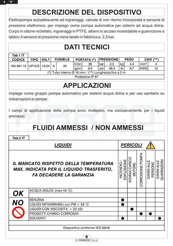
Elettropompa autoadescante ad ingranaggi, valvola di non ritorno incorporata e sensore di
pressione elettronico, per impiego come pompa automatica per sistemi ad acqua dolce.
Corpo in ottone nichelato, ingranaggi in PTFE, albero in acciaio inossidabile e guarnizione a
labbro.Il sensore di pressione viene tarato in fabbrica a 2,5 bar.
6
Tab.1 IT
CODICE TIPO VOLT
l/min 36 bar 2,5 kg 4,4 mm² 4
gpm 9,5 psi 36,3 lb 9,7 AWG 12
PRESSIONE
Protezione IP 67
12/24
CAVI (**)
164 681 15
PESO
25UP12/E
FUSIBILE
A
PORTATA (*)
(*) Tubo interno Ø 16 mm / (**) Lunghezza fino a 2 m
Tab.2 IT
ACQUA DOLCE (max 40 °C)
BENZINA •LIQUIDI INFIAMMABILI con PM < 38 °C •LIQUIDI CON VISCOSITA’ > 20 cSt •PRODOTTI CHIMICI CORROSIVI • •SOLVENTI • •
Dispositivo conforme ISO 8846
LIQUIDI
NO
OK
CO
RR
OS
ION
EP
OM
PA
DA
NN
IALL
EP
ER
SO
NE
DA
NN
IALL
EG
UA
RN
IZIO
NI
INC
EN
DIO
/E
SP
LOS
ION
E
SO
VR
AC
CA
RIC
OM
OT
OR
EIL MANCATO RISPETTO DELLA TEMPERATURA
MAX. INDICATA PER IL LIQUIDO TRASFERITO,
FA DECADERE LA GARANZIA
PERICOLI
Impiego come gruppo pompa automatico per sistemi acqua dolce e per uso sanitario su
imbarcazioni e camper.
I campi di applicazione della pompa sono molteplici, ma esclusivamente per i liquidi
ammessi:

I T
7© S.p.A.
CONDIZIONI AMBIENTALI
CICLO DI LAVORO
MOVIMENTAZIONE E TRASPORTO
INSTALLAZIONE
CONTROLLI PRELIMINARI
POSIZIONAMENTO
In condizioni di massima pressione la pompa subisce sollecitazioni superiori, pertanto si
consiglia di non utilizzarla per tempi prolungati in queste condizioni.
Peso e dimensioni del dispositivo non richiedono l'uso di mezzi di sollevamento particolari. In
caso di movimentazione manuale utilizzare i normali dispositivi di prevenzione individuale
(scarpe di sicurezza con puntale, etc...). Prima della spedizione la pompa viene
accuratamente imballata. Controllare l'imballo al ricevimento ed immagazzinare in luogo
asciutto.
Si raccomanda l'uso secondo le disposizioni vigenti in termini di sicurezza e le precauzioni di
seguito riportate:
Controllare che la pompa non abbia subito danni durante il trasporto o lo stoccaggio. Pulire
con cura le bocche di aspirazione e mandata rimuovendo eventuale polvere o materiale
d'imballo residuo. Verificare che l'alimentazione elettrica disponibile corrisponda a quella
richiesta dal dispositivo.
La pompa può essere installata in qualsiasi posizione. Fissare la pompa utilizzando viti
adeguate ai fori di passaggio.
ATTENZIONE: le temperature limite indicate si applicano ai componenti del dispositivo
e devono essere rispettate per evitare possibili danneggiamenti o malfunzionamenti.
Lo stoccaggio deve avvenire in luogo asciutto rispettando le medesime temperature.

I T
8© S.p.A.
COLLEGAMENTO ELETTRICO
La pompa va installata con collegamento elettrico dotato di protezione a fusibile dimensionato
come indicato sull'etichetta del motore.
Montare sempre gli antivibranti in gomma forniti nel kit della pompa. Il loro utilizzo consente una
riduzione consistente della rumorosità e attenua le vibrazioni generate. Il dimensionamento dei
cavi di alimentazione della pompa va effettuato in funzione della distanza della pompa dalla
batteria/generatore (vedi Tab.1 IT). L'utilizzo di cavi sottodimensionati provoca il
surriscaldamento degli stessi con reale pericolo di incendio. In tutti i casi si verifica caduta di
tensione con relativa perdita di prestazioni. La portata indicata sull'etichetta si ottiene utilizzando
un tubo di diametro interno indicato in tabella Tab.1 IT. Tubi di diametro inferiore provocano un
maggior assorbimento di corrente con conseguente rischio di surriscaldamento del motore.
IL MANCATO UTILIZZO DEL FUSIBILE FA DECADERE LA GARANZIA
Ø
Ø
Ø
Ø
Prima del collegamento accertarsi che le bocche di aspirazione e mandata siano
prive di tappi di spedizione;
Non posizionare la pompa ad una altezza eccessiva rispetto al livello minimo
possibile del fluido da trasportare. Se si supera l’altezza massima la pompa può non
adescare rovinandosi.
Evitare strozzature del tubo sia in aspirazione che in mandata in modo da
ottimizzare le prestazioni.
Si consiglia l'uso del filtro in aspirazione soprattutto con liquidi con consistente
presenza di impurità (filtro a retino passo 0,5 mm). In questo caso eseguire una
pulizia molto frequente del filtro. Il filtro di serie resiste ad una pressione massima
positiva di 0,5 bar.
Ø Usare tubazioni e connessioni in materiale resistente ai fluidi trattati ed evitare
dispersioni degli stessi nell’ambiente.
Per la corretta direzione del flusso del liquido come indicato dalla freccia sulla parte
superiore, è necessario collegare il polo positivo (+) della batteria al filo rosso che esce dalla
calotta della pompa e il polo negativo (-), al filo nero. I collegamenti elettrici vanno eseguiti
utilizzando morsettiere e connessioni adeguate con accurato serraggio dei conduttori. L'uso
scorretto può causare perdite di potenza e/o surriscaldamento dei cavi.
ATTENZIONE: è responsabilità dell'installatore eseguire una installazione a norma e
con corretto dimensionamento del circuito. È da considerarsi il grado di rischio
dell'ambiente in cui viene installato il dispositivo.

I T
9© S.p.A.
PROBLEMI E SOLUZIONICOSA VERIFICARE SE LA POMPA NON PARTE O SI ARRESTA?
Ø
Ø
Ø
Ø
Ø
Verificare l'efficienza del generatore (presenza di tensione)
Verificare se il fusibile è interrotto.
Verificare la presenza di corpi estranei nel corpo della pompa. Per effettuare ciò è
necessario svitare le quattro viti di fissaggio, togliere il piattello di chiusura ed
ispezionarne l'interno. A controllo eseguito, il piattello, va rimontato nella posizione
iniziale.
Evitare di far girare a secco per più di qualche minuto. Le pompe riscontrate
difettose per aver girato in assenza di liquido non sono coperte da garanzia
La vita media delle spazzole in condizioni di uso normale è circa 2500 ore. Dopo
tale periodo è possibile un arresto per usura delle spazzole.
PERCHE’ LA POMPA NON ADESCA ?
Ø
Ø
Ø
Ø
Ø
Ø
Ø
Ø
La pompa è posizionata a una altezza eccessiva dal livello del liquido
La pompa ha girato a secco per troppo tempo.
Lunghi periodi di inattività. In questo caso è consigliabile, prima dell’avviamento,
introdurre direttamente del liquido nel corpo pompa.
Ingresso di aria dal tubo di aspirazione a causa di possibile presenza di tagli,
mancanza di opportuna fascetta di serraggio, malfunzionamento del filtro dovuto
alla guarnizione difettata/usurata, o filtro intasato.
Ingresso di aria dal piattello a causa di viti di fissaggio lente o di guarnizione
danneggiata.
Il collegamento dei cavi elettrici non è corretto.
Presenza di ostruzioni o restringimenti del tubo di aspirazione o di mandata o di
accessori particolari (per esempio pistola automatica o connessione tipo Aquastop)
Il tubo di mandata presenta anse colme di fluido.
Ø Valvola di bypass sporca (serie VP45).
AZIONI PER FAVORIRE IL BUON FUNZIONAMENTO
Se si prevede un periodo di inattività di almeno trenta giorni, soprattutto nel caso che si
travasi acqua, si consiglia di far circolare acqua dolce ed allentare le viti del piattello. Al
riutilizzo richiudere le viti dopo un breve avviamento (pochi secondi). Verificare che nelle
condizioni di massima contropressione, l'assorbimento del motore rientri nei dati di targa.

I T
10© S.p.A.
MANUTENZIONE ORDINARIA
Ø
Ø
Ø
Controllare frequentemente e mantenere pulito il filtro in aspirazione.
Controllare mensilmente il corpo e mantenerlo pulito da eventuali impurità.
Controllare mensilmente che i cavi di alimentazione elettrica siano in buone
condizioni.
Ø Sostituire ad ogni stagione od ogni 500 ore, la girante in gomma (solo serie UP1).
INDICATORI DEL CORRETTO FUNZIONAMENTO
Ø
Ø
Ø
Temperatura della carcassa motore contenuta tra 60 °C e 70 °C
Flusso regolare e rumore costante.
Assorbimento di corrente compreso fra valori indicati nei grafici.
APERTURA
Ø Si consiglia di far intervenire del personale specializzato per effettuare riparazioni o
sostituzioni di materiale d'usura all'interno della pompa, esclusivamente con
ricambi originali; nel periodo di garanzia solo personale autorizzato di Marco S.p.A.,
pena decadimento della stessa.
SMALTIMENTOÈ responsabilità del proprietario smaltire questo prodotto mediante le strutture specifiche di
raccolta rifiuti indicate dal governo o dalle autorità governative locali.
SMALTIMENTO IMBALLO Si invita l'utente ad effettuare un'adeguata raccolta differenziata in modo da favorire il riciclo
dei materiali di cui è composto l'imballo; smaltimento con CER 15.01.01/02.
GARANZIA1) Il periodo di garanzia è di 2 anni dalla data d'acquisto come risulta dalla relativa
fattura.
2) Nel caso la fattura non fosse disponibile il periodo di garanzia di 2 anni, sarà
calcolato dalla data di fabbricazione.
3) La garanzia decade e s'intende nulla in caso d'utilizzazione non corretta o nel caso
venissero ignorate le istruzioni contenute nel presente manuale.
4) La garanzia copre solamente i difetti di fabbricazione.
5) La garanzia non copre i costi connessi di installazione e smontaggio.
6) I costi di trasporto sono rimborsabili solo nel caso in cui la garanzia è stata
debitamente riconosciuta e accettata da Marco S.p.A. Questi costi saranno limitati
ai costi di spedizione tra il magazzino di Marco S.p.A. e la sede del cliente.
7) Nessuna nota di credito o reso sarà emessa prima di un test eseguito dal controllo di
qualità di Marco S.p.A. che dichiari difettoso il prodotto.

ENG
11© S.p.A.
ELECTRONIC PRESSURE SENSOR WORKING DIRECTIONS
The electronic pressure sensor, through the use of a microprocessor, controls the pump's speed to
obtain the needed flow rate, with the following advantages:
- Noise reduction during operation
- The optimization of current consumption
- A strong reduction of electrical noise, thanks to the slow speed ramp up and ramp down of
the motor.
- A longer life for the whole system, thanks to less wear of pump parts compared to
conventional mechanical pressure switches.
The pressure sensor system is equipped with two LEDs: one blue and one multicolored (red, green, and yellow).
During normal operation, the blue LED will:
- Turn on if there's liquid in the hoses.
- Turn off when there's no liquid in the hoses.
- Flash when in priming mode. The first time it senses water it keeps flashing for 10 seconds to
make sure that the water is being pumped correctly and continuously.
If the pump goes more than five times from “priming” to “no liquid” (blue led off) the circuit
turns everything off anyway, to protect the motor and the gears from running without liquid.
The multicolored LED signals:
- With solid yellow LED, that the pressure in the hoses is not the required pressure, but the
pump is trying to reach it.
- With solid green LED, that the pump has reached the target pressure, there is still liquid
demand, but the pump's speed won't be changed because the flow rate is constant.
- With flashing green LED, the pump has reached the target pressure and there is no liquid
demand, it's in stand-by with the motor off.
- With solid or slowly flashing red LED, the motor has been short circuited, something may
have blocked the gears or there could be a problem in the connection between the pump
and circuit. The red LED flashes for 30 seconds, after which the pump is re-fed up to a
maximum of 3 attempts.
On the fourth attempt, the LED remains solid red, the pump is off and should be checked for
possible permanent damage.
To reset this warning you need to reboot the circuit or press the Reset button on the control
panel, if present.
(follows)
ENG
12© S.p.A.
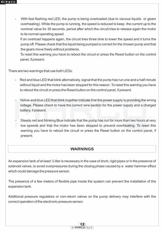
- With fast flashing red LED, the pump is being overloaded (due to viscous liquids or gears
overheating). While the pump is running, the speed is reduced to keep the current up to the
nominal value for 30 seconds, period after which the circuit tries to release again the motor
to its normal operating speed.
If an overload happens again, the circuit tries three time to lower the speed and it turns the
pump off. Please check that the liquid being pumped is correct for the chosen pump and that
the gears move freely without problems.
To reset this warning you have to reboot the circuit or press the Reset button on the control
panel, if present.
There are two warnings that use both LEDs:
- Red and blue LED that blink alternatively, signal that the pump has run one and a half minute
without liquid and the motor has been stopped for this reason. To reset this warning you have
to reboot the circuit or press the Reset button on the control panel, if present.
- Yellow and blue LED that blink together indicate that the power supply is providing the wrong
voltage. Please check to have the correct wire section for the power supply and a charged
battery, if present.
- Steady red and blinking Blue indicate that the pump has run for more than two hours at very
low speeds and that the motor has been stopped to prevent overheating. To reset this
warning you have to reboot the circuit or press the Reset button on the control panel, if
present.
An expansion tank of at least ½ liter is necessary in the case of short, rigid pipes or in the presence of
solenoid valves, to avoid overpressures during the closing phase caused by a water hammer effect
which could damage the pressure sensor.
The presence of a few meters of flexible pipe inside the system can prevent the installation of the
expansion tank.
Additional pressure regulators or non-return valves on the pump delivery may interfere with the
correct operation of the electronic pressure sensor.

© S.p.A.
PRODUCT DESCRIPTION
TECHNICAL DETAILS
APPLICATIONS
FLUIDS ALLOWED / NOT ALLOWED
ENG
Self-priming gear pump, integrated check valve and electronic pressure sensor: to be used
as automatic pump for water systems. Nickel-plated brass body, PTFE gears, stainless-steel
shaft and lip seal. The electronic pressure sensor is preset at 2,5 bar.
13
Tab.1 EN
CODE TYPE VOLT
l/min 36 bar 2,5 kg 4,4 mm² 4
gpm 9,5 psi 36,3 lb 9,7 AWG 12
PRESSURE WEIGHTFUSE
IP 67 Protection
(*) Internal tube Ø 16 mm / (**) Length up to 2 m
A 25
FLOW RATE (*)
12/24
WIRE SIZE (**)
164 681 15 UP12/E
Tab.2 EN
FRESH WATER (max 40 °C)
PETROL (GASOLINE) •FLAMMABLE LIQUIDS with PM< 38 °C •LIQUIDS WITH VISCOSITY > 20 cSt •CORROSIVE CHEMICAL PRODUCTS • •SOLVENTS • •
LIQUIDS DANGERS
WARRANTY EXPIRES IF MAX FLUID
TEMPERATURE IS EXCEEDED
FIR
E/
EX
PLO
SIO
N
MO
TO
RO
VE
RH
EA
TIN
G
PU
MP
CO
RR
OS
ION
ISO 8846 Compliant Device
INJU
RY
TO
PE
RS
ON
NE
L
DA
MA
GE
TO
SE
ALS
OK
NO
Main use as automatic pump for freshwater and sanitary water systems on boats, vans and
RV.
There are numerous fields of applications for the pump, however only exclusively with the
allowed liquids mentioned:

ENG
14© S.p.A.
TRANSPORTATION AND HANDLING
INSTALLATION
PRELIMINARY CHECKS
POSITIONING
AMBIENT CONDITIONSTEMPERATURE: RELATIVE HUMIDITY:min.-10°C 14°F-max.60°C 140°F max. 90 %
OPERATING CYCLEUnder conditions of high operating pressures the pump can be subjected to elevated
stresses and overheating and therefore should not be used for prolonged periods under such
conditions.
Due to limited weight and dimensions the pump does not require the use of any special
handling or lifting equipment. When handling manually, normal personal protective gear
should be worn (safety shoes with toe piece, etc.). The pump is carefully packed prior to
shipment. Upon receiving, the packaging should be inspected for damages and the pump
stored in a dry area.
It is recommended that the use of the pump be according to normative safety standards
and also as per the precautions listed below.
The pump can be mounted in any position. Fix the pump utilizing suitable diameter screws
corresponding to the holes.
Check that there has been no damage to the pump during transportation or storage. Both inlet and outlet ports should be carefully cleaned removing possible dust or residual packaging material. Verify that the available electrical power supply corresponds to the specification requirements.
WARNING: the above indicated temperature ranges are applicable to all components
of the pump and these limits must be respected in order to avoid any possible damage
or malfunctioning.

ENG
15© S.p.A.
To ensure the correct directional flow of the fluid as indicated by the arrow on the top plate, it is
necessary to connect the positive pole (+) of the battery supply to the red wire on the motor
end-cap and the negative pole (-) to the black wire. Electrical connections must be made
using adequate terminal blocks and connectors ensuring a tight fitment of the electrical
cables. Bad wiring can cause power losses and/or overheating of the cabling itself.
Ø
Ø
Ø
Prior to making any tube/hose connections, check that the inlet ports have no end
caps;
Do not position the pump at a excessive height with respect to the minimum level of
the fluid to be transferred. Damage may occur if this height is exceeded as the pump
may not draw fluid. Make sure that the outlet tube is empty and without chokes;
Avoid choking the inlet or outlet tubes so that efficiency is optimized.
The use of an inlet filter is recommended especially with fluids containing impurities
(mesh ASTM no. 35).
Utilize tubes and connection pieces that are resistant to the fluid types handled and
avoid any possible environmental dispersion.
Ø
Ø
In this case frequent cleaning and maintenance of the filter is
advisable. The standard filter withstands a maximum positive pressure of 0.5 bar.
The electrical installation of the pump must include a protection fuse which is suitably rated
as indicated on the motor label.
Always mount the anti vibration rubber fittings supplied with the pump kit. Their usage
ensures a consistent reduction in noise and vibration levels. Electrical cabling size should
depend on the distance between pump and battery/power supply (see Tab.1 EN). The use of
undersized cabling can cause overheating of the electrical wiring and subsequent fire
hazard. There will also be a voltage drop at the motor terminals with a consequent reduction
in efficiency. The flow rate value indicated on the motor label is obtained with internal tube
diameter indicated on Tab.1 EN. Tubes with inferior diameters will cause an increase in
current with potential risk of motor overheating.
WARRANTY EXPIRES IF NO FUSE IS UTILIZED
WARNING: it is the responsibility of the installation technician to ensure a correctly
designed circuit installation fitted according to regulations. Environmental risks must
be taken into account with the installation.

ENG
16© S.p.A.
TROUBLESHOOTING
WHY THE PUMP WILL NOT PRIME ITSELF?
CHECK POINTS IF THE PUMP HAS STOPPED OR WILL NOT START
GOOD PRACTICES ENSURING A WELL FUNCTIONING PUMP
Ø
Ø
Ø
Ø
Ø
Check the effectiveness of the battery power supply (voltage activity);
Check if the fuse has blown;
Check for any foreign matter present in the pump body. To do this, disconnect the
power supply and unscrew the four fixing screws, remove the front cover plate and
inspect the chamber. Replace the cover plate in the same initial position after
inspection;
Avoid running the pump dry for more than a few minutes. Pumps found defective
that have run dry in the absence of fluid are not covered by warranty;
The average life span of the motor commutator brushes is approximately 2500
hours under normal operating conditions. Stoppages are possible due to brush
wear and tear after such a time period.
Ø
Ø
Ø
Ø
Ø
Ø
Ø
Ø
The pump is fitted at an excessive height above the fluid level
The pump has run dry for too long a period
Long periods of inactivity. In this case it is advisable to add liquid directly into the
chamber before start-up
Air leak at the suction pipe due to the following reasons, possible cuts in the pipe,
inadequate hose clamps, malfunctioning of the filter due to defective/worn seals or
filter clogged
Air leak at the front plate cover due to the following reasons, loose fixing screws,
poor effectiveness of the seal
Faulty electrical cable connections
Presence of obstructions or restrictions in the suction or delivery pipes or the use of
special devices (eg. automatic spray pistol or Aquastop)
Presence of liquid loops in the outlet tube
Ø Dirty bypass valve (VP45 series)
If it is expected that the pump will not be used for a period of at least 30 days, especially in the
case of usage with water, it is advisable to run fresh water through it and to then loosen the
front plate screws. Upon re-use, run the pump briefly (a few seconds) and tighten the screws
again. Check under conditions of maximum operating pressure that the motor current value
is within the motor label specifications.

ENG
17© S.p.A.
NORMAL MAINTENANCE
INDICATORS THAT THE PUMP IS FUNCTIONING CORRECTLY
TO OPEN THE PUMP
ENVIRONMENTAL DISPOSAL
WARRANTY
PACKAGING ENVIRONMENTAL DISPOSAL
Ø
Ø
Ø
Check frequently and keep the inlet filter clean.
Check every month the chamber and keep clean from any foreign matter.
Check every month that electrical wiring is in good condition.
Ø Replace the rubber impeller every season or every 500 hours (for UP1 series).
Ø
Ø
Ø
Temperature of body and motor frame is within 60°C and 70°C (140 °F - 158 °F);
Regular flow and constant noise levels;
Amp-draw within the limits indicated in the diagrams.
Ø It is recommended that a specialized service technician be consulted for any
repair work or the replacement of worn out internal components, exclusively with
original spare parts; during the warranty period, only by authorized Marco S.p.A.
personnel, failing which the warranty will expire.
It is the responsibility of the owner to dispose of this product by means of the specific refuse
collection structures indicated by the government or the local governing authorities.
The user is invited to effect a proper waste separation, in order to facilitate the recycling
of the materials of which the packing is composed.
1) The Warranty period is 2 years from date of purchase on production of the
appropriate sales invoice.
2) Should the original sales invoice not be available, then the 2 year warranty
period will be valid from production date.
3) The Warranty becomes null and void in the case of incorrect utilization or
disregard of the instructions contained herein.
4) The Warranty only covers original production defects.
5) The Warranty does not cover any related installation costs involved.
6) Transport costs are refundable only in the case where warranty has been duly
accepted by Marco Spa and they will be limited to the actual shipment costs
between Marco Spa warehouse and the client's delivery address.
7) No credit notes or replacement items will be issued prior to the receipt and
proper testing of any Marco goods that are deemed faulty.

© S.p.A.
SCHEDA DI ASSEMBLAGGIO / EXPLODED VIEWPos. Q.tà Descrizione
1 1 CORPO POMPA
2 2 TIRANTE3 2 O-RING4 1 CARCASSA5 1 INDOTTO6 1 CALOTTA7 2 O-RING8 2 RONDELLA9 2 DADO10 1 VALVOLA DI NON RITORNO11 1 LINGUETTA12 1 INGRANAGGIO TRAINANTE13 1 INGRANAGGIO FOLLE
Pos. Q.tà Descrizione
14 1 O-RING
15 1 RACCORDO16 1 O-RING17 1 PIATTELLO18 4 VITE19 1 SENSORE DI PRESSIONE20 1 O-RING21 1 TAPPO DI SFIATO22 1 RACCORDO23 4 O-RING24 2 PORTAGOMMA25 1 FILTRO26 4 ANTIVIBRANTE
Pos. Q.ty Description
1 1 PUMP BODY
2 2 ROD3 2 O-RING4 1 PUMP FRAME5 1 ARMATURE6 1 BRUSH HOLDER7 2 O-RING8 2 WASHER9 2 NUT10 1 NON RETURN VALVE11 1 KEY12 1 IDLE GEAR13 1 DRIVING GEAR
Pos. Q.ty Description
14 1 O-RING
15 1 NIPPLE16 1 O-RING17 1 TOP PLATE18 4 SCREW19 1 ELECTRONIC PRESSURE SENSOR20 1 O-RING21 1 AIR VENT CAP22 1 NIPPLE23 4 O-RING24 2 TUBE OUTLET25 1 FILTER26 4 ANTIVIBRATION MOUNT
ENGI T
18

© S.p.A.
INGOMBRI / DIMENSIONS
10
3/8
"6
22
1/2
"
72
27/8
"4
11
5/8
"
113
41/2
"
58
21
/4"
80
31
/8"
Ø1
75
/8"
15
5/8
"
ENG I T
19

0
1 0
2 0
3 0
0 0 ,5 1 1 ,5 2 2 ,5 3
b a r
A
A (12V) A (24V)
© S.p.A.
DIAGRAMMI / DIAGRAMS
DIAGRAMMA PORTATAFLOW RATE DIAGRAM
DIAGRAMMA ASSORBIMENTIAMPERE-DRAW DIAGRAM
ENGI T
20
0
10
20
30
40
0 0,5 1 1,5 2 2,5 3
bar
l/m
in

164 681 15 - UP12/E 12/24V Autoclave con controllo elettronico / Electronic Gear pump
ENG I T
21© S.p.A.
DICHIARAZIONE DI CONFORMITA’ C.E. E.C. DECLARATION OF CONFORMITY
Confermiamo che il prodotto: We confirm that the product:
EN 55014-1
Electromagnetic compatibility.Requirements for household appliances,electric tools, and similar apparatus.Part 1: Emission.
Compatibilità elettromagnetica. Requisiti per gli elettrodomestici,gli utensili elettrici ed apparecchi similari.Parte 1: Emissione.
Questa dichiarazione è rilasciata sotto la responsabilità esclusiva di:
This declaration is given under the sole responsibility of:
MARCO S.P.A.
Via Mameli 10 - 2501 Cas enedolo - Brescia - Italy 4 t
Tel. 030/2134.1 Fax 030/2134.300
EN 55014-2
Electromagnetic compatibility.Requirements for household appliances,electric tools, and similar apparatus.Part 2: Immunity.
Compatibilità elettromagnetica. Requisiti per gli elettrodomestici,gli utensili elettrici ed apparecchi similari.Parte 2: Immunità.
Questa dichiarazione è valida per tutti gli articoli prodotti secondo la documentazione tecnica che è parte di questa dichiarazione. In caso di eventuali verifiche pertinenti alla Compatibilità Elettromagnetica sono state applicate le seguenti normative:
This declaration is valid for all products which are produced in accordance with the technical documentation which is a part of this declaration. For verification of conformity with regard to the Electromagnetic Compatibility the following standards are applied:
è conforme alla Direttiva 2014/30/UE (ex. 2004/108/CE) relativa alla compatibilità elettromagnetica e alla
Direttiva 2006/42/CE relativa alle macchine.
is in conformity with the Directive 2014/30/EU (ex.2004/108/EC) relating to electromagnetic compatibility and
with the Directive 2006/42/EC relating to the machines.

© S.p.A.
NOTE / NOTES
ENGI T
22


Questo documento e' proprieta' di Marco S.p.A la riproduzione e l'uso sono vietati.
Tutti i diritti sono riservati.
Per ulteriori informazioni vedere nostro sito internet - www.marco.it
Marco S.p.A Via Mameli 10 - 25014 Castenedolo (Brescia) – Italia
tel. +39 030 2134.1 / Fax +39 030 2134.300
Property of MARCO S.p.A reproduction prohibited. All rights reserved.
For further information visit our web site - www.marco.it
Marco S.p.A Via Mameli 10 - 25014 Castenedolo (Brescia) – Italy
tel. +39 030 2134.1 / Fax +39 030 2134.300