elementary ugra - · pdf filethe transducer •these crystals ... this block needle...
TRANSCRIPT

ELEMENTARY UGRAChristian R. Falyar, CRNA, DNAP
Department of Nurse Anesthesia
Virginia Commonwealth University
Objectives
• Discuss the physics of sound
• Explain how sound tissue interaction creates echoes
• Review how ultrasound uses different strength echoes generate an image
• Describe why nerves appear differently at various locations on the body
• Name the basic components and functions of an ultrasound system
• Identify factors that can improve the success of an UGRA procedure
• Review complications of UGRA and strategies that can used to reduce/prevent them

What is sound?
• Sound is a form of mechanical energy.
• Sound travels at different speeds through different
substances, or media.
• As sound travels through media, it can be reflected, refracted,
scattered, reverberated and ultimately attenuated.
• Frequency is determined by the number of cycles
(compressions and rarefactions) that occur in a second
• Wavelength is inverse to the frequency (i.e. the higher the
frequency the shorter the wavelength)
• Amplitude describes the energy of the wave, and is not
related to frequency
• Ultrasound used in in diagnostic imaging involves frequencies
greater than 1MHz.

What is sound?

Propagation velocities

What is sound?
Rarefactions (low pressure)
Compressions (high pressure)

Thoughts on frequency...
High frequency
• More cycles occur per
second
• Images are higher
resolution
• Greater attenuation of the
sound waves limits the
depth at which tissue can
be imaged
Low frequency
• Fewer cycles occur per
second
• Greater tissue penetration
but lower resolution
• Less attenuation allows
for imaging of deeper
structures

Thoughts on frequency…
High frequency Low frequency

Generation of sound waves
• A wave is generated when an ultrasound system
applies an electrical field to crystals located on
the transducer
• These crystals convert the electrical energy to
mechanical energy; this is known as the
piezoelectric effect
• The sum of the waves is an ultrasound beam
• These beams are emitted in pulses, with each
beam being two to three cycles in length

Generation of sound waves
piezoelectric crystals
outer housing
alternating current to create potential difference
backing material
power supply
acoustic insulator
matching layer
AlternatingCurrent

Sound wave propertiesTr
ansd
uce
r
Fresnel Zone(Near Zone)
Fraunhofer Zone(Far Zone)
Focal Zone
A
B

Sound/Tissue interaction
• The echoes interpreted by
ultrasound result from the
different acoustic
impedances of tissues
• The amount of reflection,
refraction, scattering, and
attenuation is dependent
on the degree of difference

Acoustic impedance

Sound/Tissue interaction
Reflection Refraction Scattering Attenuation
Incident Wave
Reflected Wave
Impedance Z1
Impedance Z2
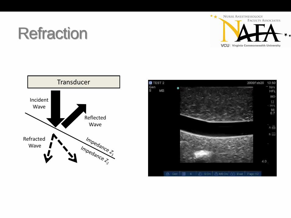
Incident
WaveReflected
Wave
Refracted
Wave
Impedance Z1
Impedance Z2
Transducer
Incident
WaveIncident
Wave
Attenuated
Wave

Reflection

Reflection
Specular Diffuse
Refraction
Incident Wave
Reflected Wave
RefractedWave

Rayleigh scattering
• Rayleigh scattering occurs at interfaces involving structures of small dimensions (such as a red blood cell).
• This creates a relatively uniform average amplitude in all directions.
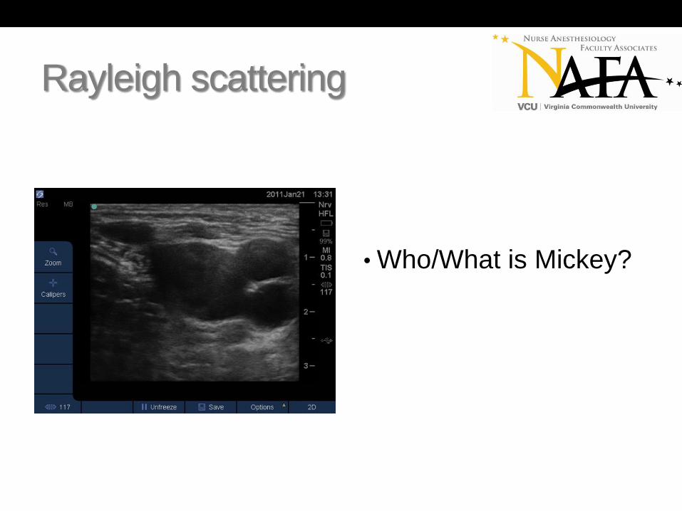
Rayleigh scattering
• Who/What is Mickey?

Attenuation
• The decreasing intensity of a sound wave as it passes through tissue.
• In medical ultrasound, attenuation is the result of the interaction of sound with tissue.
• The attenuation coefficient is the relation of attenuation to distance, and depends on the tissues traversed and the frequency of the ultrasound wave.
• Higher frequency waves are more severely attenuated than lower frequency waves.

Attenuation
Attenuation

What creates my picture?
• It’s all in the math!!!
• The computer assigns a
color in a grey scale based
on the strength of returning
echoes to form the image.
• This process repeats itself
hundreds of times a
second resulting in real-
time imaging.
What do tissues look like?
• Nerves – in cross section appear as round “honeycomb” structures
• Tendons – appear similar to nerves, but become flat and disappear when followed proximally along an extremity
• Vascular Structures – typically appear as anechoic circular structures in cross-section. Will appear tubular in longitudinal view
• Fat – appears hypoechoic with streaks of irregular hyperechoic lines
• Fascia – appears linear hyperechoic structures marking tissue boundries
• Muscle – appears feather-like in longitudinal view; appears as a “starry night in cross-section, more hypoechoic than nerves
• Pleura and Air – pleura appears hyperechoic, with the lung appearing hypoechoic underneath
• Cysts – similar appearance to vascular structures, cysts will also appear as hypoechoic in longitudinal view
• Bone – appear as hyperechoic linear structures with hypoechoic regions underneath (shadowing)

Not all nerves look the same…
Tibial and Common PeronealNerves
C5 C6 C7 Roots of the Brachial Plexus

Nerves vs. Tendons
• Nerves and tendons can
both appear as hyper-
echoic circles in the
periphery.
• They can be differentiated
by following their course
proximally along the
extremity

What do tissues look like?
• Adipose tissue appears
hypoechoic with streaks of
irregular hyperechoic lines
• It is the most superficial
layer imaged

What do tissues look like?
• Arteries, veins, and cysts
all appear as anechoic
structures
• Arteries are pulsatile, while
veins can be easily
compressed
• Arteries and veins will
appear as tube-like
structures in long view,
cysts will remain round

What do tissues look like?
• Muscle appears
heterogeneous on
ultrasound because of the
varying acoustic
impedances between the
cell structures, the water
content within the cells,
and the intertwined fascia

What do tissues look like?
• Lung tissue appears as a
thin hyperechoic line with
“tails” (areas of
reverberation) beneath it

What do tissues look like?
• Bone is a significant
specular reflector, creating
a hyperechoic area with
shadowing beneath it

Doppler
• Animals use Doppler in
nature and it has been
adapted by man for many
purposes
• Doppler is dependent on
the angle of insonation
• Either the sender or
receiver must be moving
• Doppler is used to create
an image

Artifacts
• An artifact is any phenomenon that affects the
acquisition or interpretation of an ultrasound
image
• Artifacts can occur because of properties within
the tissue itself, or created by the anesthetist
• The most commonly seen artifacts are air
artifact, shadow artifact, acoustic
enhancement, and reverberation

Artifacts
• Air artifact occurs when
the transducer does not
fully contact the skin
• This is commonly seen
when imaging smaller
anatomical structures
• Applying sufficient gel to
the transducer and
applying even pressure will
correct this

Artifacts
• Shadow artifact (red
arrows) results from the
severe amount of
attenuation when an
ultrasound wave comes in
contact with bone or other
tissue with a high
attenuation coefficient
Artifacts
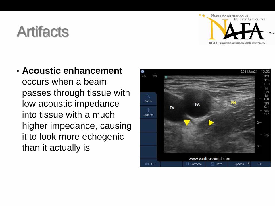
• Acoustic enhancement
occurs when a beam
passes through tissue with
low acoustic impedance
into tissue with a much
higher impedance, causing
it to look more echogenic
than it actually is

Artifacts
• Reverberation occurs
sound reflects off of strong
specular reflectors such as
this block needle creating
an illusion there are
“multiple” needles below
the actual one

Scanning basics
• Most ultrasound systems have the same basic
features. It is important to understand what each
function does prior to performing any procedure.
These include:
• B-Mode imaging
• Depth
• Contrast adjustment (gain)
• Color-flow Doppler
• Image recording capability (still images and video)

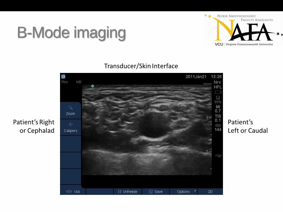
B-Mode imaging
• B-Mode is the default
image on all ultrasound
systems
• Pressing the 2D button will
reset the system to the
default mode, regardless
of the systems current
configuration
B-Mode imaging

B-Mode imaging
Cross-Section/Short-Axis Longitudinal/Long-Axis

Depth
• Depth determines how far
into the tissues echoes are
interpreted
• Increasing the depth,
decreases resolution
• In general, the structure of
interest is kept in the
center of the screen

Depth – Median nerve
Proper depth Too Deep

Gain
• Gain compensates for
attenuation of the
ultrasound wave
• It amplifies RETURNING
echoes
• Gain can be adjusted
either in the near field, far
field, or overall image

Gain – Just right

Gain
Too little gain Proper gain

Gain
Too much gain Proper gain

Time Gain Compensation
(TGC)
• TGC allows for control of
artifacts such as reflection,
shadowing and attenuation
• Increasing the TGC
increases the amplitude of
ultrasound wave at specific
levels of the image

TGC – No adjustment

TGC – With compensation

TGC - Dropout
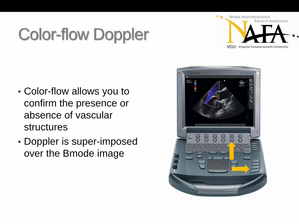
Color-flow Doppler
• Color-flow allows you to
confirm the presence or
absence of vascular
structures
• Doppler is super-imposed
over the Bmode image

Color-flow Doppler

Color-flow Doppler

Image and video recording
• There are no current
guidelines as to what
should be documented
when performing an UGRA
procedure
• Image and video
recordings are valuable
tools for assessing block
performance

Images

Videos

Transducers
• The transducers used for UGRA are either linear
or curved linear array transducers
• Transducers are the link between the ultrasound
system and the tissue. They are complex and
play a large role in determining the resolution and
accuracy of an image
• Transducer selection is determined by the depth
of the structures to be imaged

Linear array

Curved array

Transducer handling
• Notch pointed to the anesthetist left or toward the patient’s head
• Hold the transducer flat against the patient’s skin for maximum contact
• Hold the transducer close to the skin surface, the ulnar aspect of the hand should rest on the patient
• Be gentle, but firm; sound waves penetrate tissue regardless of the pressure applied

Transducer handling
Proper Hand Position Poor Hand Position
Transducer manipulation
• In 1999, the American Institute for Ultrasound
Medicine (AIUM) established terminology to
describe transducer manipulation.
• These terms do not include specification of
direction (i.e. proximal, distal, clockwise)
• In general, a transducer can be manipulated in
five ways: sliding, tilting, rocking, rotating and
compressing.

Sliding
• To optimally display an
image, the transducer
must be manipulated
• This allows for smooth
scanning motion and
anatomy visualization
• Sliding allows the provider
to find the appropriate
level to perform the block

Tilting
• To optimally display an
image, the transducer
must be manipulated
• This allows for smooth
scanning motion and
anatomy visualization
• Tilting can be used to
correct air artifact and
increase contact of the
transducer
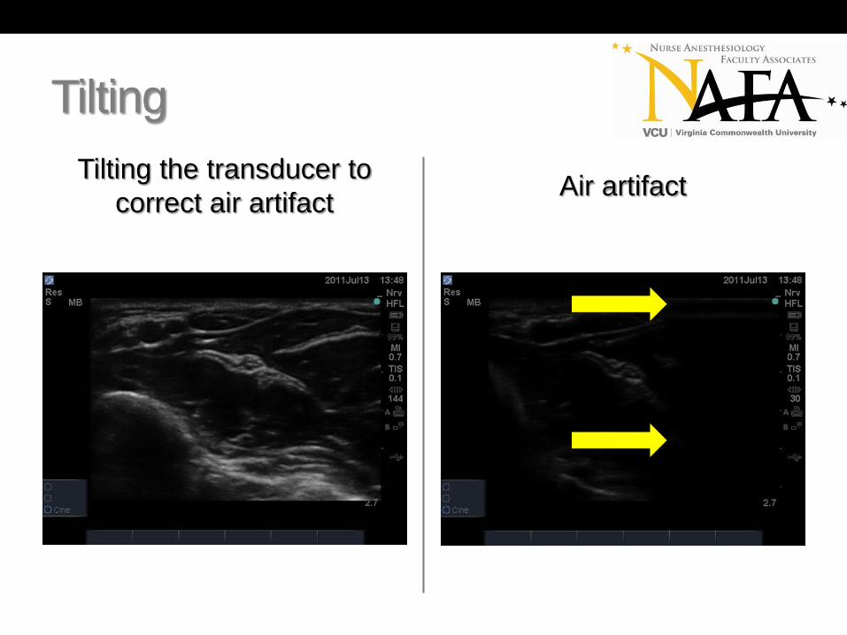
Tilting
Tilting the transducer to
correct air artifact Air artifact

Rocking
• To optimally display an
image, the transducer
must be manipulated
• This allows for smooth
scanning motion and
anatomy visualization
• Rocking improves nerve
image by accounting the
effect of anistropy

Rotating
• To optimally display an
image, the transducer
must be manipulated
• This allows for smooth
scanning motion and
anatomy visualization
• Rotating allows the
provider to optimize all
structures in the image on
the same plane

Compressing
• To optimally display an
image, the transducer
must be manipulated
• This allows for smooth
scanning motion and
anatomy visualization
• Compressing can be used
to decrease space from
the skin to the desired
structure being imaged

Transducer orientation
• Proper placement of the transducer in relation to
the patient’s position is key to obtaining a correct
image
• In general, the transducer should be oriented to
the anesthetist’s left in cross-section or toward
the patient’s head in longitudinal view
• When the transducer is not properly oriented, a
“mirror-image” will result

Transducer orientation

Transducer orientation

Transducer orientation
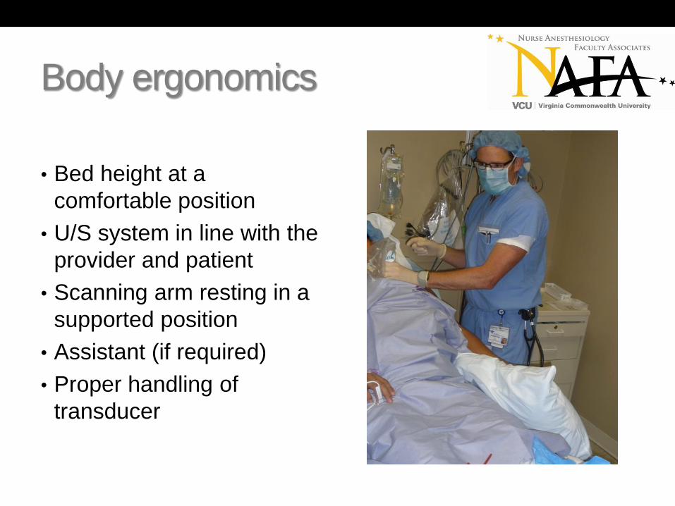
Body ergonomics
• Bed height at a
comfortable position
• U/S system in line with the
provider and patient
• Scanning arm resting in a
supported position
• Assistant (if required)
• Proper handling of
transducer

Body ergonomics
Poor ergonomics Good ergonomics

What now?
• You have the right patient, discussed the
proposed anesthetic technique, obtained
consent, verified the site, and gathered your
supplies
• Select the appropriate frequency transducer
• Prior to scanning, imagine how the image should
appear on the monitor
• Apply the principles of body ergonomics
• Apply sufficient gel to the transducer
• Jump in!

B-Mode imaging
• What am I seeing?!
• What can I do to make it
better?!

B-Mode imaging
Optimizing your image
• Use PLENTY of gel. Gel acts as a coupler
between the transducer and the skin, and
improves the image quality
• Ensure your transducer is initially perpendicular
and flat against the skin
• Optimize your depth so the structures you wish to
image are in the center of the screen
• Adjust your gain to make picture look uniform

Needle visualization
In-Plane Out-of-Plane

In-Plane/Long-Axis

Out-of-Plane/Short-Axis

Anatomy, anatomy, anatomy…
• Know your anatomy. Most nerves blocked using
regional anesthesia are in close proximity to
arteries, veins, or other vital organs (i.e. the
lungs)
• The key is being able to anticipate what you will
be seeing before you start scanning.
• Proper placement of your transducer will ensure
correct orientation of the picture

Anatomy, anatomy, anatomy…

Or…

Anistropy
• The term anistropy implies dependency on an
angle
• In ultrasound it is used to describe a change in
amplitude of received echoes when the angle of
insonation has changed.

Anistropy
Transducer Rocked Transducer at 90 degrees

Strategies to increase safety
• Ultrasound itself is a non-invasive modality that causes no complications to the patient
• Ultrasound-guided procedures introduce a needle and/or local anesthetic into a patient increasing the potential for complications
• Needle insertion should first be practiced using a phantom numerous times, with emphasis placed viewing the entire needle as it passes through the tissue
• Strategies such as wiggling, or hydro-location can be used to verify the location of the needle tip

Wiggling
• Tilt the needle to a more
superficial position,
reducing the angle of
insertion and bringing
angle closer to 90 degrees
• Wiggling from side-to-side
or slightly in and out until
the needle is seen
• Once the position is
determined, slight rotation
of the transducer will help
identify the tip

Hydro-location
• Injecting 1-2cc’s of fluid
through the block needle
will help determine the if
the part of the needle
visualized is the tip
• Using D5W will increase
nerve conduction if a nerve
stimulator is being used

Complications of UGRA
• Pneumothorax
• Hemothorax
• Vascular puncture
• Local Anesthetic toxicity (seizure, cardiac arrest)
• Venous thrombosis/Hematoma
• Dysrhythmias
• Neurologic complications (brachial plexus injury,
Horner syndrome)
• Parathesias

Risk factors
• Inexperience
• Large catheter size
• Morbid obesity (BMI > 30)
• Severe dehydration
• Coagulopathy
• Multiple attempts

Questions?

References
• Aldrich J E. Basic physics of ultrasound imaging. Crit Care Med. 2007;35(5 Suppl):S131-S137.
• Zagzebski JA. Physics and instrumentation in Doppler and B-mode ultrasonography. In: Zweibel WJ. Introduction to Vascular Ultrasonography. 4th ed. Philadelphia, PA: W.B. Saunders Company; 2000:17-43.
• Marhofer P, Frickey N. Ultrasonographic guidance in pediatric regional anesthesia part 1: Theoretical background. Paed Anaesth. 2006;16(10):1008-1018.
• Sites B D, Brull R, Chan V W, et al. Artifacts and pitfall errors associated with ultrasound-guided regional anesthesia. part I: understanding the basic principles of ultrasound physics and machine operations. Reg Anesth Pain Med2007;32(5):412-418.
• Falyar CR. Ultrasound in anesthesia: applying scientific principles to clinical practice. AANA J. 2010 Aug; 78(4):332-40.
• Kremkau F W. Doppler Ultrasound: Principles and Instruments. Philadelphia, PA: W.B. Saunders Company; 1990:5-51

References
• Taylor K J, Holland S. Doppler us. part i. basic principles, instrumentation, and pitfalls. Radiology. 1990; 174(2):297-307.
• Gray AT. Atlas of ultrasound-guided regional anesthesia. Philadelphia, PA. Saunders, Elsevier; 2010:45-67.
• Pollard BA, Chan VW. An introductory curriculum for ultrasound-guided regional anesthesia: a learner’s guide. Toronto. University of Toronto Press Inc.; 2009:23-28.
• Bigeleisen PE, ed, Orebaugh SL, Moayeri N, et al. Ultrasound-guided regional anesthesia ad pain medicine. Baltimore, MD. Lippincott Williams & Wilkins; 2010:26-33.
• Kossoff G. Basic physics and imaging characteristics of ultrasound. World J Surg. 2000; 24:134-142.