elektroniczne źródła prądowe - mysinski.wieik.pk.edu.plmysinski.wieik.pk.edu.pl/mpuandmcu/serial...
TRANSCRIPT

2017-01-08
1
Serial interfaces
Erasmus 2015/2016, WIEiK, PK
Input/Output Port
A port is a device:
• to receive the bytes from external peripheral(s) [or device(s) or processor(s) or controllers] for reading them later using instructions executed on the processor or
• to send the bytes to external peripheral or device or processor using instructions executed on processor.
Erasmus 2015/2016, WIEiK, PK

2017-01-08
2
Parallel and serial comunication
• The communication links across which computers—or parts of computers—talk to one another may be either serial or parallel.
• A parallel link transmits several streams of data simultaneously along multiple channels (e.g., wires, printed circuit tracks, or optical fibres);
• A serial link transmits a single stream of data using for example only one or two wires.
Erasmus 2015/2016, WIEiK, PK
Input/Output Port Types
There are two major types of input/output ports, parallel port and serial port
Types of parallel ports – Parallel input port – only to receive data from external devices
– Parallel output port – only to send data from external devices
– Parallel input/ouput port – to receive or send data from external devices
Types of Serial ports – Serial input port - only to receive data from external devices
– Serial output port – only to send data from external devices
– Serial input/output port – to receive or send data from external devices
There are two major types of serial ports, synchronous serial port and asynchronous serial port.
Erasmus 2015/2016, WIEiK, PK

2017-01-08
3
Parallel input/output port
Parallel communication, where several bits are sent as a whole, on a link with several parallel channels.
Master
D0 D1 D2 D3 D4 D5 D6 D7
/WR /RD
Slave
Erasmus 2015/2016, WIEiK, PK
Serial Port
• A port, or interface, that can be used for serial communication, in which only 1 bit is transmitted at a time.
• A serial port is a general-purpose interface that can be used for almost any type of device, including modems, mice (PS/2 or USB), hard disk (SATA), and printers (USB).
• Old types of printers are connected to a parallel port (in PC computer it is LPT port).
Erasmus 2015/2016, WIEiK, PK

2017-01-08
4
Serial communication
Example of serial communication, one receiver/transmitter, full duplex
Master
TxD Slave
RxD RxD TxD
Erasmus 2015/2016, WIEiK, PK
TxD RxD TxD RxD TxD RxD TxD RxD
Example of serial communication, many receivers/transmitters, half duplex
common lines
Terminal resistor
Terminal resistor
Serial communication – serial port
• In telecommunication and computer science, serial communication is the process of sending data one bit at a time, sequentially, over a communication channel or computer bus.
• This is in contrast to parallel communication, where several bits are sent as a whole, on a link with several parallel channels.
• Serial communication is used for all long-haul communication and most computer networks, where the cost of cable and synchronization difficulties make parallel communication impractical.
• Serial computer buses are becoming more common even at shorter distances, as improved signal integrity and transmission speeds in newer serial technologies have begun to outweigh the parallel bus's advantage of simplicity (no need for serializer and deserializer, or SerDes) and to outstrip its disadvantages (clock skew, interconnect density). The migration from PCI to PCI Express is an example.
Erasmus 2015/2016, WIEiK, PK

2017-01-08
5
Parallel communication and serial communication
• Although a serial link may seem inferior to a parallel one, since it can transmit less data per clock cycle, it is often the case that serial links can be clocked considerably faster than parallel links in order to achieve a higher data rate.
• A number of factors allow serial to be clocked at a higher rate: – Clock skew between different channels is not an issue (for unclocked
asynchronous serial communication links). – A serial connection requires fewer interconnecting cables (e.g.,
wires/fibres) and hence occupies less space. The extra space allows for better isolation of the channel from its surroundings.
– Crosstalk is less of an issue, because there are fewer conductors in proximity.
• In many cases, serial is a better option because it is cheaper to implement. Many Integrated Circuits (ADC, DAC, EEPROM memory, RTC, temperature sensors, ….) have serial interfaces, as opposed to parallel ones, so that they have fewer pins and are therefore less expensive. Erasmus 2015/2016, WIEiK, PK
Serial modes
R T R
T
A full-duplex (FDX), or sometimes double-duplex system, allows communication in both directions, and, unlike half-duplex, allows this to happen simultaneously. Land-line telephone networks are full-duplex, since they allow both callers to speak and be heard at the same time. A good analogy for a full-duplex system would be a two-lane road with one lane
for each direction.
T/R R/T
A half-duplex (HDX) system provides communication in both directions, but only one direction at a time (not simultaneously). Typically, once a party begins receiving a signal, it must wait for the transmitter to stop transmitting,
before replying.
T R
Systems that do not need the duplex capability use instead simplex communication in which one device transmits and the others just "listen". Examples are broadcast radio and television, garage door openers, baby monitors, wireless
microphones, radio controlled models, surveillance cameras, and missile telemetry
Erasmus 2015/2016, WIEiK, PK
full-duplex
half-duplex
simplex

2017-01-08
6
Synchronous serial port
• The Serial Peripheral Interface Bus or SPI (pronounced as either ess-pee-eye or spy) bus is a synchronous serial data link standard, named by Motorola, that operates in full duplex mode.
• Devices communicate in master/slave mode where the master device initiates the data frame.
• Multiple slave devices are allowed with individual slave select (chip select) lines.
• Sometimes SPI is called a four-wire serial bus, contrasting with three-, two-, and one-wire serial buses.
• SPI is often referred to as SSI (Synchronous Serial Interface).
Erasmus 2015/2016, WIEiK, PK
Synchronous serial port -SPI
The SPI bus can operate with a single master device and with one or more slave devices.
D0 D1 D2 D3 D4 D5 D6 D7
Clock signal
A timing diagram showing clock polarity and phase of signals
Data signal
Rising egde of clock signal
Erasmus 2015/2016, WIEiK, PK
Chip enable signal
/SS
SCK
MOSI
2017-01-08
7
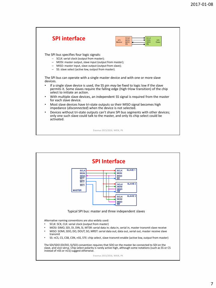
SPI interface
The SPI bus specifies four logic signals: – SCLK: serial clock (output from master); – MOSI: master output, slave input (output from master); – MISO: master input, slave output (output from slave); – SS: slave select (active low, output from master).
The SPI bus can operate with a single master device and with one or more slave devices. • If a single slave device is used, the SS pin may be fixed to logic low if the slave
permits it. Some slaves require the falling edge (high→low transition) of the chip select to initiate an action.
• With multiple slave devices, an independent SS signal is required from the master for each slave device.
• Most slave devices have tri-state outputs so their MISO signal becomes high impedance (disconnected) when the device is not selected.
• Devices without tri-state outputs can't share SPI bus segments with other devices; only one such slave could talk to the master, and only its chip select could be activated.
Erasmus 2015/2016, WIEiK, PK
SPI Interface
Alternative naming conventions are also widely used: • SCLK: SCK, CLK: serial clock (output from master) • MOSI: SIMO, SDI, DI, DIN, SI, MTSR: serial data in; data in, serial in, master transmit slave receive • MISO: SOMI, SDO, DO, DOUT, SO, MRST: serial data out; data out, serial out, master receive slave
transmit • SS: nCS, CS, CSB, CSN, nSS, STE: chip select, slave transmit enable (active low, output from master) The SDI/SDO (DI/DO, SI/SO) convention requires that SDO on the master be connected to SDI on the slave, and vice-versa. Chip select polarity is rarely active high, although some notations (such as SS or CS instead of nSS or nCS) suggest otherwise. Erasmus 2015/2016, WIEiK, PK
Typical SPI bus: master and three independent slaves

2017-01-08
8
SPI Interface
SPI is used to talk to a variety of peripherals, such as: • Sensors: temperature, pressure, ADC, touchscreens, video game controllers • Control devices: audio codecs, digital potentiometers, DAC • Camera lenses: Canon EF lens mount • Communications: Ethernet, USB, USART, CAN, IEEE 802.15.4, IEEE 802.11,
handheld video games • Memory: flash and EEPROM • Real-time clocks • LCD displays, sometimes even for managing image data • Any MMC or SD card (including SDIO variant) • For high performance systems, FPGAs sometimes use SPI to interface as a
slave to a host, as a master to sensors, or for flash memory used to bootstrap if they are SRAM-based.
The SPI bus is a de facto standard. However, the lack of a formal standard is reflected in a wide variety of protocol options. Different word sizes are common. Every device defines its own protocol, including whether or not it supports commands at all. Some devices are transmit-only; others are receive-only. Chip selects are sometimes active-high rather than active-low. Some protocols send the least significant bit first.
Erasmus 2015/2016, WIEiK, PK
SD card interface
Power supply 2.0V - 3.6V
Semester zimowy 2015/2016, WIEiK- PK 16

2017-01-08
9
Asynchronous start/stop operation
Before signalling will work, the transmiter and receiver must agree on the signalling parameters:
• full or half-duplex operation • the number of bits per character (from 5 up to 9) • endianness – the order in which the bits are sent • the speed or bits per second of the line (often incorrectly referred to as the Baud
rate). Some systems use automatic speed detection. • both sides must agree to use or not use parity • if parity is used, both sides must agree on using odd or even parity • the number of stop bits sent must be chosen (the number sent must be at least what
the receiver needs) Between computers (microcontrollers), the most common configuration used was "8N1": eight bit characters, with one stop bit and no parity bit. Thus 10 Baud times are used to send a single character, which has the nice side-effect that dividing the signalling bit-rate by ten results in the overall transmission speed in characters per second.
Erasmus 2015/2016, WIEiK, PK
Master
TxD
Slave
RxD RxD TxD
Asynchronous serial communication
• The idle, no data state is high-voltage (state ‘1’), or powered. • Each character is sent as a logic low START bit, a configurable number of data bits (usually 8,
but legacy systems can use 5, 6, 7 or 9), an optional parity bit, and one or more logic high STOP bits.
• The START bit signals the receiver that a new character is coming. The next five to eight bits, depending on the code set employed, represent the character. Following the data bits may be a parity bit. The next one or two bits are always in the mark (logic high, '1') condition and called the stop bit(s).
• They signal the receiver that the character is completed. Since the START bit is logic low (‘0’) and the STOP bit is logic high (‘1’) there are always at least two guaranteed signal changes between characters.
Idle state
START Bit = ‘0’ START Bit for synchronisation
8-bits data, from 5 bits up to 9 bits
D0 D1 D2 D3 D4 D5 D6 D7
Parity Bit
STOP Bits=‘1’ 1, 1.5 or 2
Next START Bit
Character framing for 8-bits data include 10 bits.
Erasmus 2015/2016, WIEiK, PK

2017-01-08
10
A Universal Asynchronous Receiver/Transmitter - UART
• A Universal Asynchronous Receiver/Transmitter, abbreviated UART is a piece of computer hardware that translates data between parallel and serial forms.
• UARTs are commonly used in conjunction with communication standards such as EIA, RS-232, RS-422 or RS-485.
• The universal designation indicates that the data format and transmission speeds are configurable. The electric signaling levels and methods (such as differential signaling etc.) are handled by a driver circuit external to the UART.
• A UART is usually an individual (or part of an) integrated circuit used for serial communications over a computer or peripheral device serial port.
• UARTs are now commonly included in microcontrollers. A dual UART, or DUART, combines two UARTs into a single chip.
• Many modern ICs now come with a UART that can also communicate synchronously; these devices are called USARTs (universal synchronous/asynchronous receiver/transmitter). Erasmus 2015/2016, WIEiK, PK
RS232
• An RS-232 port (for example COM1, COM2 in PC) was once a standard feature of a personal computer for connections to modems, printers, mice, data storage, uninterruptible power supplies, and other peripheral devices.
• However, the low transmission speed, large voltage swing, and large standard connectors motivated development of the USB (Universal Serial Bus), which has displaced RS-232 from most of its peripheral interface roles.
• Many modern personal computers have no RS-232 ports and must use an external converter (USB/RS232) to connect to older peripherals.
• RS-232 devices are still found, especially in industrial machines or scientific instruments.
Erasmus 2015/2016, WIEiK, PK
A DB-25 and DB-9 connector as described in the RS-232 standard

2017-01-08
11
RS232 interface
Erasmus 2015/2016, WIEiK, PK
Transmitter Receiver
+15V
-15V
+5V
-5V
-15V
+15V
+3V
-3V
Max -25V
Max +25V
State „0”
State „1”
0V
Sygnały w RS232 • Data signals
• Txd – Transmitted Data • Rxd – Received Data
• Control signals • DTR – Data Terminal Ready • DSR – Data Set Ready • RTS – Request to Send • CTS – Clear to Send • RI – Ring Indicator • DCD – Data Carrier Detected
• SG – signal Ground
DTE – Data Terminal Equipment DCE – Data Comunication Equipment
DTE
TxD
RxD
RTS
DSR
DTR
CTS
RI
DCD
SG
DTE
TxD
RxD
RTS
DSR
DTR
CTS
RI
DCD
SG
Minimum connection for a two devices
DTE
TxD
RxD
SG
DTE
TxD
RxD
SG
UART – RS232, RS422, RS485
Voltage level translator for RS232
Voltage level translator for RS485 Voltage level translator for RS422
Erasmus 2015/2016, WIEiK, PK
With a UART serial port, for example, by adding to the microcontroller a suitable transmitter and receiver (logic/voltage level translator) we can get a standard interface RS232, RS422 or RS485.

2017-01-08
12
Examples of serial communication architectures • UART – Universal Asynchronous Receiver/Transmitter • USART- Universal Synchronous /Asynchronous Receiver/Transmitter • I2C – Inter Integrated Circuit Bus or TWI, 2-wire – Two Wire Interface • SPI – (Serial Peripheral Interface Bus), 4-wire interface, • 1-wire - interface • SMBus (System Management Bus) • PMBus (Power Management Bus ) • DDC - (VESA Display Data Channel) • SATA – (Serial Advanced Technology Attachment) • PCI Expres – PCI-E (Peripheral Component Interconnect Express) • IEEE 1394 interface - FireWire (Apple), i.LINK (Sony), Lynx (Texas
Instruments) • HDMI - (High-Definition Multimedia Interface) • USB – (Universal Serial Bus ) • Ethernet • Midi • DMX512
Erasmus 2015/2016, WIEiK, PK
RS423, RS422 – interface full-duplex
Erasmus 2015/2016, WIEiK, PK
RxD TxD
+ -
GND1 GND2 UG
Rt
RxD TxD + -
GND1 GND2 UG
Rt + -
+5V +5V
+5V +5V

2017-01-08
13
RS485 – interface half-duplex,
Erasmus 2015/2016, WIEiK, PK
TxD
GND1
Rt Rt
+ -
+ - RxD
RxD/TxD
Device no 1
TxD + -
+ - RxD
RxD/TxD
Device no 2
TxD + -
+ - RxD
RxD/TxD
Device no 3
TxD + -
+ - RxD
RxD/TxD
Device no 4
GND2 GND3 GND4
Terminal resistor
A B A B A B A B
Industry serial interfaces
• RS232, RS422, RS423, RS485, 2xRS485
• CAN
• Ethernet
• CC Link
• HART
Erasmus 2015/2016, WIEiK, PK

2017-01-08
14
I2C - interface
Erasmus 2015/2016, WIEiK, PK
MASTER
SCL SDA
SCL SDA SLAVE 1
+Vcc
R1 10k
R2 10k
Pull up resistors
SDA – data signal
SCL SDA SLAVE 2
SCL SDA SLAVE 3
SCL SDA SLAVE 4
GND
SCL – clock signal
• I²C ("eye-squared cee" or "eye-two-cee" Inter-Integrated Circuit; generically referred to as "two-wire interface") is a multi-master serial single-ended computer bus invented by Philips that is used to attach low-speed peripherals to a motherboard, embedded system, cellphone, or other electronic device.
• Since the mid 1990s, several competitors (e.g., Siemens AG (later Infineon Technologies AG, now Intel mobile communications), NEC, Texas Instruments, STMicroelectronics (formerly SGS-Thomson), Motorola (later Freescale), Intersil, etc.) brought I²C products on the market, which are fully compatible with the NXP (formerly Philips's semiconductor division) I²C-system.
• As of October 10, 2006, no licensing fees are required to implement the I²C protocol. • However, fees are still required to obtain I²C slave addresses allocated by NXP.
VESA Display Data Channel
Erasmus 2015/2016, WIEiK, PK
VGA connector DB15 Pin 12 – SDA Pin 15 – SCL
DVI connector Pin 7 – SDA Pin 6 – SCL
2017-01-08
15
Wireless interface
Radio
• WiFi, WIMAX
• GSM/SMS, GSM/GPRS, LTE
• Bluetooth 2.0, 4.0, ZigBee
Optic
• IrDA (Infrared Data Association)
Erasmus 2015/2016, WIEiK, PK
UART/USART in ATMEGA32 based on: http://www.embedds.com/programming-avr-usart-with-avr-gcc-part-1
• USART is found in most of AVR microcontrollers (except few most of Tiny ones). Atmega32 microcontroller has one USART module that is highly configurable and flexible.
• Datasheet provides a list of supported features including Full Duplex, Asynchronous and Synchronous operation, Master or Slave operation mode, variable frame size, even or odd parity bits, one or two stop bits, several interrupt sources and even more.
Setting USART hardware • USART is usually referred as RS232 interface what is wrong. USART stands for
communication protocol while RS232 stands for signal logic levels and control signals. RS232 now is a thing of the past, but there are still lots of boards that support RS232.
• RS232 communication standard needs different signal levels than AVR microcontroller can provide. AVR usually gives 5V (or 3V) for logical “1″ and 0V for logical “0″. RS232 standard uses +3V to 25V for logical “0″ and -3V to -25V for logical “1″. For this there is a special TTL to RS232 converter chip used like MAX232. But if you look for development boards you will see than majority boards now uses USB communication standard and instead of using MAX232 there are an USB to TTL converters like FT232.
Erasmus 2015/2016, WIEiK, PK

2017-01-08
16
UART/USART in ATMEGA32
The Universal Synchronous and Asynchronous serial Receiver and Transmitter (USART) is a highly flexible serial communication device. The main features are: • Full Duplex Operation (Independent Serial
Receive and Transmit Registers) • Asynchronous or Synchronous Operation • Master or Slave Clocked Synchronous
Operation • High Resolution Baud Rate Generator • Supports Serial Frames with 5, 6, 7, 8, or 9
Data Bits and 1 or 2 Stop Bits • Odd or Even Parity Generation and Parity
Check Supported by Hardware • Data OverRun Detection • Framing Error Detection • Noise Filtering Includes False Start Bit
Detection and Digital Low Pass Filter • Three Separate Interrupts on TX Complete, TX
Data Register Empty, and RX Complete • Multi-processor Communication Mode • Double Speed Asynchronous Communication
Mode
Erasmus 2015/2016, WIEiK, PK
SPI in ATMEGA32
The Serial Peripheral Interface (SPI) allows high-speed synchronous data transfer between the ATmega32 and peripheral devices or between several AVR devices. The ATmega32 SPI includes the following features: • Full-duplex, Three-wire
Synchronous Data Transfer • Master or Slave Operation • LSB First or MSB First Data Transfer • Seven Programmable Bit Rates • End of Transmission Interrupt Flag • Write Collision Flag Protection • Wake-up from Idle Mode • Double Speed (CK/2) Master SPI
Mode
Erasmus 2015/2016, WIEiK, PK
2017-01-08
17
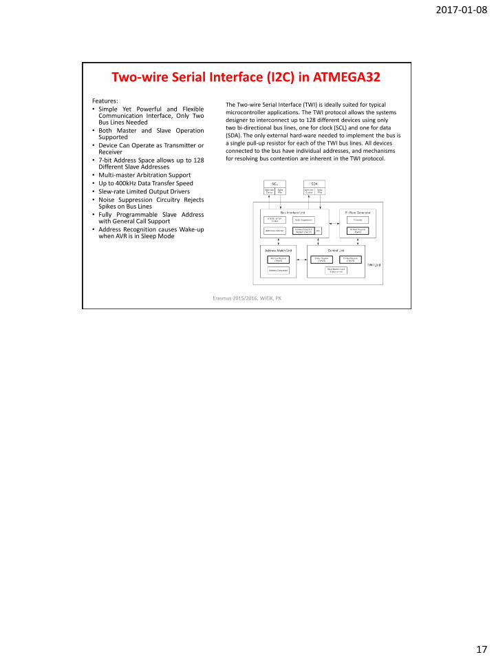
Two-wire Serial Interface (I2C) in ATMEGA32
Features: • Simple Yet Powerful and Flexible
Communication Interface, Only Two Bus Lines Needed
• Both Master and Slave Operation Supported
• Device Can Operate as Transmitter or Receiver
• 7-bit Address Space allows up to 128 Different Slave Addresses
• Multi-master Arbitration Support • Up to 400kHz Data Transfer Speed • Slew-rate Limited Output Drivers • Noise Suppression Circuitry Rejects
Spikes on Bus Lines • Fully Programmable Slave Address
with General Call Support • Address Recognition causes Wake-up
when AVR is in Sleep Mode
Erasmus 2015/2016, WIEiK, PK
The Two-wire Serial Interface (TWI) is ideally suited for typical microcontroller applications. The TWI protocol allows the systems designer to interconnect up to 128 different devices using only two bi-directional bus lines, one for clock (SCL) and one for data (SDA). The only external hard-ware needed to implement the bus is a single pull-up resistor for each of the TWI bus lines. All devices connected to the bus have individual addresses, and mechanisms for resolving bus contention are inherent in the TWI protocol.