electrosurgical generator and smoke evacuation system
TRANSCRIPT

Electrosurgical Generator andSmoke Evacuation System
Service Manual
Catalog NumbersESU-110 & ESU-220
U t a h M e d i c a l P r o d u c t s , I n c .
7043 South 300 West • Midvale, Utah 84047801.566.1200 • 800.533.4984 USA & Canada

©1994, 2009 by Utah Medical Products, Inc.
Finesse® is a registered trademark of Utah Medical Products, Inc.
The Finesse® Electrosurgical Generator and Smoke Evacuation Systemis patented under U.S. patent number 5,160,334.
The contents of this manual may not be reproduced without expresswritten consent of Utah Medical Products, Inc.
The information contained in this manual was correct at press time.However, unscheduled changes may have taken place that may ren-der portions of this manual inaccurate. Please contact Utah MedicalProducts, Inc. for updated information if errors or changes in thecontents of this manual are suspected.
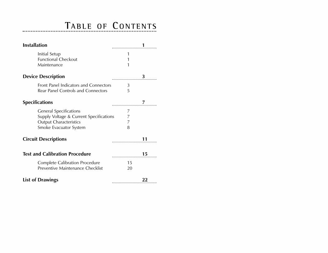
Installation 1
Initial Setup 1Functional Checkout 1Maintenance 1
Device Description 3
Front Panel Indicators and Connectors 3Rear Panel Controls and Connectors 5
Specifications 7
General Specifications 7Supply Voltage & Current Specifications 7Output Characteristics 7Smoke Evacuator System 8
Circuit Descriptions 11
Test and Calibration Procedure 15
Complete Calibration Procedure 15Preventive Maintenance Checklist 20
List of Drawings 22
TABLE OF CONTENTS


INSTALLAT ION
Initial Setup
Unpack the Finesse® unit from its packing material. Retain the pack-ing material and box for future use.
Inspect the unit for any visible damage or missing accessories. Ifdamage is found, contact your Utah Medical Products' representativefor replacement parts.
The unit should be placed on a flat, level surface at working heightwithin six feet of the operating area.
Connect the footswitch (if used).
Plug the Finesse® unit into an appropriately rated wall outlet.
Functional Checkout
1. Install handswitch pencil into the three-point connector onfront panel. If a non-switching "footswitch" pencil is used,install this pencil into the port marked with the "active port"icon on the front panel.
2. Toggle the main power switch to the "on" position. Threethings should happen:
• the green lamp in the power switch should light,• the red alarm lamp on the front panel should light, and• an interrupted alarm tone should sound.
3. If the three indicators listed in step 2 above do not occur,check to verify that:
• the power cord is securely plugged in on both ends,• the three fuses on the rear panel of the unit are installed,• these fuses are not blown, and the room outlet is active.
4. Connect a dispersive pad with a single contact surface to thedispersive pad receptacle on the front panel. The red alarmlamp should go out and beeping should cease.
5. Briefly operate the cut control on the handswitch. The yellow"cut" lamp should light, a tone should be emitted from theinternal speaker, and the vacuum pump should come on andstay on approximately five seconds after the cut control buttonis released. If none of this occurs try another handswitch. Ifthe vacuum motor does not come on, check the position ofthe vacuum control switch and the 3-amp fuse on the backpanel.
6. Repeat step 5 above with the coag switch rather than the cutswitch. All operation should be the same except that the blue"coag" lamp illuminates rather than the yellow "cut" lamp.
7. Repeat steps 5 and 6 above using the cut and coag pedals ofthe foot switch. All indications should be the same as theywere using the hand switch.
If any of the above items do not check good, please contact UtahMedical Products Customer Service for assistance.
Maintenance
Daily MaintenanceAt the end of any day that the Finesse® unit is used, the primary fil-ter, catalog number ESU-501, should be changed. Using a glovedhand, remove the filter from the front panel by gently pulling andtwisting the filter housing. Discard the filter pack with other medicaldisposables.
CleaningThe Finesse® system exterior may be wiped clean with alcohol orhousehold spray cleaner applied to a cloth. Do not use acetone.Do not apply cleaning agent directly to the unit.
The loop and ball electrodes, pens, dispersive pads, and speculum
Finesse Service Manual 1

tubing/ reducer are supplied as single patient use items. Cleaningand/or resterilization of these items should not be attempted.
Annual MaintenanceThe primary internal filter, catalog number ESU-700, should bechanged on an annual basis.
To change the internal filter:
Remove the three button head screws running along the topedge of the rear panel of the Finesse® unit, using a 5/64" hexkey. Gently pull the top cover up and away from the fronthousing.
Release the front filter adapter from the front housing byremoving the three externally visible button head screws with a5/64" hex key. Gently pull the adapter away from the frontpanel. With a gloved hand, remove the used primary internalfilter by pulling it away from the vacuum motor inlet. Note theoriginal positioning of the filter. Dispose of the used filter asyou would dispose other medical disposables.
Insert the new filter onto the vacuum motor inlet in the sameorientation as the previous filter. Replace the front filteradapter onto the front housing, taking care to verify that theprimary internal filter inlet seats properly into the front filteradapter. Secure the front filter adapter to the front panel byreplacing the three button head screws.
Replace the top cover onto the chassis by inserting the lip onthe front of the cover into its locator slot in the front housingand then drop the rear of the top cover into place. Align thethree screw holes and replace the three button head screws.
For the care and performance of your Finesse® electrosurgical unit,the Emergency Care Research Institute (ECRI) recommends the estab-lishment of a program for inspection and preventive maintenance.ECRI Procedure/Checklist 411 recommends that minor inspectionsshould be performed every six months and major inspections shouldbe done on an annual basis.
Information on the ECRI Procedure/Checklist can be obtained bycalling ECRI at (610) 825-6000 or visiting www.ecri.org.
Finesse Service Manual2

DEV ICE DESCR I PT ION
The Finesse® unit consists of two major modules, the electrosurgicalgenerator and the smoke evacuation system. A single power switchcontrols both modules; the smoke evacuation system is automaticallyswitched on and off relative to footswitch or handswitch activation ofthe electrosurgical generator.
Figure 1. Finesse® front panel connectors and indicators
Front Panel Indicators and Connectors
Connectors and indicators on the Finesse® front panel are shown inFigure 1 and subsequently described.
1. Vacuum Level Switch. This three-position rocker switch con-trols the smoke evacuation system flow rate.
The upper, or "normal" position runs the vacuum motor at alevel that is sufficient to draw the smoke plume away from thesurgical site during the LETZ® procedure.
The lower or "high" position of the switch runs the vacuummotor at a higher speed, creating a flow rate approximately
40% greater than the normal setting with the same tubing con-figuration. This setting should be used whenever the distalsmoke removal tube has a very small diameter, or in any othercircumstance where the smoke is not being completelyremoved.
The smoke evacuation system motor can be disabled by settingthis switch to the center "off" position (designated by "0").
The vacuum system does not have an activation switch of itsown. It is turned on automatically by internal circuitry when-ever the cut/blend or coag modes are activated, and shuts offafter a delay of five seconds from the time the electrosurgicalgenerator output is deactivated. In addition to its conven-ience, this intermittent operation is beneficial to the life of thefilters and to the vacuum motor itself.
2. Cut/Blend Indicator Lamp. This yellow lamp is illuminatedwhenever cutting or blend voltages are applied to the activelead. Illumination of this lamp is accompanied by an audiotone having a pitch lower than the tone heard during a fault inthe dispersive electrode monitoring circuit or during operationin the coag mode.
3. Main Power (on/off) switch. This switch must be turned on toenable all functions of the instrument. A green light internal tothe switch illuminates when the unit is powered on.
4. Cut/Blend Output Control Knob and Indicator. This knob isused to specify the output level desired for the intended cut.The adjacent digital readout indicates the output setting.
Due to line voltage and thermal variations, it is normal for thenumber displayed on the digital indicator to vary by one ortwo digits while the control knob is stationary. While this vari-ation truly reflects the relative output setting, it is of no clinicalsignificance and will not affect cutting quality.
The cut mode display can be continuously adjusted between"05" and "99". In general, higher output levels are required forthicker or wider loop electrodes or for deeper submersion of
Finesse Service Manual 3

the cutting electrodes in the tissue. These principles are dis-cussed in the “Principles of Electrosurgery” section of theFinesse® Operator's Manual.
As mentioned in the safety warnings of the operator's manual,this knob should not be turned up to correct an apparentpower output deficiency without first verifying that all connec-tions are in good order and the patient dispersive electrode isstill properly applied.
5. Coag Indicator Lamp. This blue lamp is illuminated whenevercoag voltage is applied to the active lead. Illumination of thislamp is accompanied by an audio tone having a pitch lowerthan the tone heard during a fault in the dispersive electrodemonitoring circuit but has a pitch higher than the tone heardduring operation in the cut mode.
6. Coag Output Control Knob and Indicator. This knob is usedto specify the output level desired for the intended coag oper-ation. The adjacent digital readout indicates the output set-ting.
Due to line voltage and thermal variations, it is normal for thenumber displayed on the digital indicator to vary by one ortwo digits while the control knob is stationary. While this vari-ation truly reflects the relative output setting, it is of no clinicalsignificance and will not affect coagulation quality.
The coag mode display can be continuously adjusted between"05" and "75". Smaller or finer electrodes require a lower set-ting and larger electrodes will require a higher setting. Lowersettings on this knob may be used for desiccation coagulation.
The principles of coagulation by desiccation and fulgurationare explored in the “Principles of Electrosurgery” section of theFinesse® Operator's Manual.
7. Patient Dispersive Electrode Receptacles. Three sets of dis-persive pad receptacles are provided to accommodate the dis-persive pad cable configurations that are commonly available.
The left-most socket pair is provided to take two redundantleads out to a dispersive electrode. If either of these leads hasbroken continuity, or if either lead is omitted, the red patientalarm warning lamp in the center of the terminal block illumi-nates and current from the generator is automatically shut off.
The center dispersive pad connector is a phone plug thataccommodates the phone plugs provided with many of theavailable pads. Redundant leads are used, and the continuitysensing circuit warns of a compromised dispersive electrodeconnection.
The right-most rectangular socket is compatible with most ofthe remainder of the available pads. Like the other two recep-tacles, it accommodates dual-conductor cables.
8. Patient Alarm Indicator Lamp. This red lamp is illuminatedwhenever the generator is disabled due to one of the followingconditions:
1) Incomplete redundant dispersive electrode connections(accompanied by intermittent high-pitched alarm tone);
2) Simultaneous activation of both cut and coag modes("cross-key") (accompanied by continuous high-pitchedalarm tone); or
3) Activation of the output safety circuit (accompanied by acontinuous high pitched audio tone).
The output safety circuit continuously monitors the output ofthe generator and will disable the system when an unexpecteddiscrepancy between the displayed output setting and the out-put power is detected. The main power switch must be tog-gled off to clear this condition.
9. Monopolar Handswitch Receptacle. This connector consistsof three banana sockets which accommodate most of thereusable and disposable hand-switching electrosurgical pensthat are available.
The left-most of the three sockets, marked with the "activeport" icon, accommodates a non-switching pen for monopolar
Finesse Service Manual4

cutting loops, balls, and other surgical tools. When these pensare used, the electrosurgical current must be activated by afootswitch connected to the footswitch connector on the rearpanel of the unit.
10. Mode Select Switch. This switch allows the selection of theappropriate mix of cut and coagulation activity for the per-formed procedure.
In the cut mode, a continuous sinusoid voltage is applied tothe surgical tool in use. If the loop wire diameter is smallenough, it will cut through tissue very cleanly with very littlesurface heating that would stop bleeding.
In the blend modes, the same loop electrode will cut cleanlythrough the tissue while the surface of the cut is heated toaccomplish a degree of coagulation. "Blend 1" produces slightcoagulation, whereas "Blend 2" and "Blend 3" produce succes-sively higher degrees of coagulation.
In switching between these modes the total output deliveredto the surgical tool is maintained at a constant setting as set bythe output control knob above the switch. Further informationuseful in selecting blend modes is given in the “Principles ofElectrosurgery” section of the Finesse® Operator's Manual andthe “Technical Data” section of this manual.
11. Smoke Filter Connection. This connection, the large circularstructure on the face of the front panel, accepts the externaldisposable filter pack which provides first- and second-stageparticulate removal and odor adsorption.
Rear Panel Controls and Connectors
Controls and connectors on the Finesse® rear panel are shown inFigure 2 and are described below.
Figure 2. Finesse® rear panel connectors
1. Footswitch Connector. This connector accommodates two-pedal footswitches designed to separately control cut and coagmodes.
2. AC Power Cord Connector. This connector is a three-contactconnector for use with high quality three wire power cords.
3. Fuse Sockets. These three sockets house the fuses that pro-vide overcurrent protection for the Finesse® unit. They arelabeled with the appropriate fuse specifications for these cir-cuits. Use only the correct fuses as specified by these labels.
4. Audible Tone Volume Control. This control adjusts the vol-ume of the cut and coag mode activation tones. Due to inter-national regulatory requirements, alarm tones are not affectedby this control, and are not adjustable.
Finesse Service Manual 5

Finesse Service Manual6

SPEC I F I CAT IONS
General Specifications
Dimensions: 14.0" (35.6 cm) W x 14.2" (36.1 cm) D x 7.1"(18.0 cm) H
Weight: 22 lbs. (10.0 kg)IEC Classification: Class I, Type CFEU Directive: Compliant with 93/42/EEC (Medical Device
Directive) (ESU-220 only)Mode of Operation: Continuous operation with intermittent load-
ing (10s/30s)
Supply Voltage & Current Specifications
The Finesse® unit can be obtained in either a 115 VAC (catalog no.ESU-110) or 230 VAC (catalog no. ESU-220) configuration.
Supply Voltages (voltages are AC rms)Nominal Voltage: 115 volts 230 voltsRegulated Range: 100-130 volts 200-260 voltsOperating Range: 90-140 volts 180-280 voltsFrequency: 45-65 Hz 45-65 Hz
Output Power vs. Supply VoltageWithin the Regulated Range listed above, the output power into a500Ω load remains within ±15% of the power delivered at the cen-ter of this range in cut and blend modes and ±30% in coagulationmode.
Maximum Supply Current and Power (total)115 V model 230 V model
Idle State: 0.5 A, 60 W 0.3 A, 70 WCut Mode: 6 A, 690 W 4.5 A, 1035 WCoag Mode: 6 A, 690 W 4.5 A, 1035 W
Overcurrent ProtectionThe Finesse® 115 V model is protected by a 6.25 amp slo-blo fuse ineach lead to the primary winding of the main power transformer.
The Finesse® 230 V model is protected by a 4 amp slo-blo fuse ineach lead to the primary winding of the main power transformer.
Output Characteristics
Output FrequenciesThe frequency of the interrupted waveforms is 450 kHz ± 50 kHz.Interrupted patterns for blend and coagulation modes repeat at 28kHz ± 3 kHz.
Output Values at Maximum SettingsMode Settinga Duty Cycleb Max Voltaged
Cut 99 100% 1000Blend 1 99 62.5% 1925Blend 2 99 50% 2050Blend 3 99 37.5% 2200
Coag 75 c 3500
a Output Setting specified is power in watts, plus or minus 15%, deliv-ered into a 500Ω patient load.
b Duty Cycle is ratio of burst duration to burst-plus-rest duration.c Coag pulse consists of two high voltage cycles followed by lower
amplitude ringout for about 10 μsec, repeated at 28 kHz.d Maximum voltage is peak-to-peak, open circuit. Lower values are
permitted.
Floating Patient LeadsThe dispersive and active leads are RF isolated as defined byANSI/AAMI standard HF-18/1993.
Output Power vs. LoadOutput display is calibrated to be relative power in watts at a load of500Ω.
Finesse Service Manual 7

The negative-feedback output stage limits the output voltage underhigh resistance loads. The same feedback circuit attempts to main-tain the output voltage under low resistance loads so that the cuttingcharacteristics are quite uniform throughout the entire cut. SeeFigure 3 and Figure 4 for output power vs. load data for cut, blendand coag modes. Cut mode maximum output power is 150 watts at200Ω patient load.
Output Power vs. Displayed SettingThe output of the Finesse® unit increases linearly with adjustment ofthe front panel output settings. Figure 5 and Figure 6 show the typi-cal output power of each of the five modes over the full controlrange. Both curves shown indicate output at 500Ω load resistance.
Output Safety Circuit SpecificationsThe Finesse® system is equipped with a safety circuit that monitorsthe output signal levels and disables all unit functions when the out-put exceeds the expected "nominal" output. The alarm system canonly be reset by turning off the main power switch.
The output safety alarm system will activate if the output voltageexceeds 180 volts rms or exceeds the nominal output voltage by50%, whichever is greater.
Audible Tone/Alarm SystemVolume: 65 dBA min @ 1m (3.3 ft)
Frequency: Cut 0.8 kHz nominalCoag 1.5 kHz nominalAlarm 3.0 kHz nominal
Smoke Evacuator System
Supply Voltages (all voltages are AC rms)Nominal Voltage: 115 volts 230 voltsOperating Range: 90-140 volts 180-280 voltsFrequency: 45-65 Hz 45-65 Hz
Maximum Supply Current and PowerAt the Nominal Voltage, the maximum supply current is 2 amps.Maximum supply power for the ESU-110 is 230 watts and for theESU-220 is 460 watts.
Overcurrent ProtectionThe smoke evacuation motor is protected by a 3 amp fuse in the hotlead.
Air Flow vs. Supply VoltageAt a supply voltage within the Regulated Range, the air flow througha new disposable filter coupled to a 15 cm long 7 mm ID tube is notless than 100 liters per minute (3.5 cubic feet per minute) at the"high" setting and not less than 70 liters per minute (2.5 cfm) at the"normal" setting.
Smoke Evacuation DurationThe smoke evacuation system will begin running immediately onactivation of the electrosurgery module and remain running five sec-onds after the output power is deactivated.
Disposable Filter CartridgeThe Finesse® Filter Pack, catalog number ESU-501, consists of apleated HEPA paper filter followed by a compartment containingactivated charcoal.
Filter Life
The Finesse® Filter Pack, to ensure total elimination of odors betweenprocedures, should be replaced on a daily basis. However, thethree-stage filtration system has been tested to effectively removeodors and particles for up to 15 electrosurgical procedures. Over aperiod of time the external disposable filter pack can be a source ofodor and possible viral contamination. Therefore, it is recommend-ed that the external filter pack be changed every day or after 15 pro-cedures if more than 15 procedures are performed in a single day.
Finesse Service Manual8

Finesse Service Manual 9
Figure 3. Typical outputpower vs. load resistancefor cut and blend modes
Figure 4. Typical outputpower vs. load resistance
for coag mode
Figure 5. Typical outputpower vs. output settingfor cut and blend modes
Figure 6. Typical outputpower vs. output setting
for coag mode
Third-Stage Internal FilterThe Finesse® Internal Filter, catalog number ESU-700, is a pleatedULPA filter element.
Filter Life
Annual replacement is recommended.
Combined Filter SystemParticle Removal Efficiency
In laboratory tests, spherical particles with a mean diameter of 0.1microns were removed with a minimum efficiency of 99.999%.
Finesse Service Manual10

CIRCU I T DESCR I PT IONS
Note: Schematics for the Finesse® generator will be made availableon request to qualified technical personnel.
Power SupplyThe power supply for all electronic functions is derived from theinput line supply through a multi-winding transformer mounted onthe floor of the unit. Circuits are conventional, non-switching sup-plies using bridge rectifiers, electrolytic filter capacitors, and seriesregulators. Except for the line connections, transformer, and fuses, allDC power supply components are mounted on the power supplyboard (see functional diagram on page 28 and assembly diagram onpage 24).
The 200 volt supply furnishes power to the preamplifier and finaloutput stages. This supply is not actively regulated; however thevolt-amp capacity of the transformer itself is sufficient to maintainsufficient voltage under load to provide the set cutting or coag out-put, and the preamplifier and output stages are feedback regulated atthe RF level so that the variation in cutting output over a largechange in supply line voltage is small.
The 30 volt regulated DC supply begins with a 28 volt rms secondarywinding on the main power transformer winding. A bridge rectifierwith a capacitor input filter converts this to approximately 40 voltsDC for use by both the 30 volt and 15 volt regulators. The 30 voltregulator is a three terminal linear regulator.
The 15 volt regulated DC supply for powering the CMOS logic chipsalso uses the 40 volt bridge with a three terminal linear regulator. Aresistor between the regulator and the 40 volt unregulated supplyprotects it from excessive current in the event of a shorted compo-nent.
The five volt regulated supply furnishes power to the LED displaydevices on the display board. A 5 volt regulator chip is fed from aseparate winding on the main power transformer.
Output Level Control and DisplayThe cut/blend and coag modes of operation are separately controlledwith parallel circuitry. However, only the operation of the cut/blendcontrol circuit will be described.
The desired output for cutting is set by turning the cut/blend outputcontrol knob on the front panel until the digital output indicator dis-plays the correct value. Voltage from the front panel potentiometeris routed to the A-D input on the digital display board. R3 in thispath is provided to set the display to read "99" at the fully clockwisesetting of the front panel knob.
The A-D converter converts the adjusted voltage at this point to adigital value which can be manipulated by the main display proces-sor. A linearization curve is programmed in the processor for each ofthe cut and three blend modes so that the proper output controllevel is presented digitally to the D-A converter at any setting fromthe front panel.
The D-A converter translates the output of the processor to an analogvoltage which, after some additional scaling, will act as drive to thepower generation circuits. Two potentiometers on the logic boardallow for offset and gain adjustment of this voltage. A summingamplifier at the output of the D-A converter provides a means foramplifying, attenuating, or offsetting the control voltage and, also,provides a mixing point for subtraction of the voltage signal fed backfrom the generator output.
The adjusted output voltage, mixed with the feedback signal, is rout-ed to individual variable-gain buffer amplifiers that are provided forsetting the drive levels of each mode in final calibration. The outputsof these power level control amplifiers are connected to a bank oftransistor switches which act to select the proper voltage for eachselected mode of operation and present it to the DC-AC converter.These transistor switches are logically controlled by signals from themode switch on the front panel and by the cut/blend and coag acti-vation signals from the power board.
The DC-AC converter is a FET chopper whose drain voltage is theconditioned output control DC voltage and whose gate is driven
Finesse Service Manual 11

from the high frequency waveform generator. This converter is trans-former coupled to the base of the output preamplifier which, in turn,drives the final output stage.
Waveform GenerationEach of the cut, blend, and coag modes are distinguished from eachother by the voltage waveforms delivered to the output terminals.All of these waveforms are originally derived from a 450 kHz squarewave oscillator on the logic board. In the pure cut mode, theunmodified 450 kHz square wave is applied to the gate of the chop-per FET in the DC-AC converter. In the blend modes and in thecoag mode, the continuous square wave is interrupted for variousdurations. Blend 1 removes 6 cycles of every 16 for a duty cycle of62.5 percent. Blend 2 removes 8 cycles of 16 for a duty cycle of 50percent. Blend 3 removes 10 of 16 for a duty cycle of 37.5 percent,and the coag mode removes 15 of 16 for a duty cycle of 6.25 per-cent.
Cycle removal for these functions is accomplished using a ripplecounter, an array of gates, and a D-type flip flop. The 450 kHz oscil-lator is disabled unless either the cut/blend switching circuit or thecoag switching circuit is active.
RF Power AmplificationAfter the variable-amplitude, output-control voltage is converted toAC by the DC-AC converter, the resultant RF signal is transformercoupled to the input of the preamplifier and amplified in two stagesto the level necessary for performing electrosurgery. The preamplifierconsists of a bipolar power transistor with collector-to-base localfeedback and a transformer coupled to the final output stage. Withthe exception of the power transistor itself, which is mounted on theback panel heat sink, all components of the preamplifier are mount-ed on the RF power board.
The final output stage uses four parallel power transistors mountedon a fan-cooled internal heat sink. Other components of this circuit,which consist of biasing resistors, output transformer, and outputcoupling capacitors are mounted on the RF power board.
The RF output is coupled to the active and dispersive output termi-nals through an output transformer with series capacitors in bothleads. This results in an output which is RF isolated from ground andwhich is incapable of conducting low frequency currents which maycause serious neuromuscular stimulation in the patient.
Feedback CircuitFeedback control of the output is provided to 1) limit the maximumopen circuit output voltage, 2) regulate the output to optimum levelsunder various cutting conditions, and 3) diminish the sensitivity ofthe cutting output to line voltage variations. The output voltage isdetected by a high frequency bridge rectifier connected across thesecondary of the output transformer. This rectifier produces a DCoutput which is proportional to the peak RF voltage across the outputterminals. This proportional voltage is applied to the LED input of aopto-isolator device, and the emitter voltage from the isolator is fedback to the cut/blend gain and offset control amplifier on the digitaldisplay board.
With this circuit in place, an increase in the output, caused by adecrease in load current or any other cause, will be detected andsubtracted from the output control signal, which will, in turn, resultin less drive to the preamplifier and, therefore, less change in theoutput. Conversely, any attempted decrease in the output voltagewill be suppressed by the opposite action.
The degree of feedback control is adjustable using R333 on thepower board. This resistor is adjusted as part of the factory calibra-tion procedure. It is interactive with the power gain adjustments.Changing it without corresponding adjustment of the gain will resultin miscalibration of the generator.
Function Switching CircuitsThe commonly available hand switches for electrosurgery have threewire connections to the generator with two single pole switches forcut/blend and coag. The active lead to the electrosurgical imple-ment is the common wire for both switching functions. To maintainRF isolation of the generator output, it is necessary that the hand
Finesse Service Manual12
switching circuit be electrically isolated from ground. To achieve thisresult, optical isolators are driven by op amp comparators betweenthe hand switch wires and the generator logic elements. Betweenperiods of surgical activity the comparator outputs are low and theoptical isolators stay in the "off" condition. When one of the twohandswitches is activated, the corresponding comparator toggles highand the optical isolator switches "on". When current flows througheither of these optical isolators, the various gates that activate the450 kHz oscillator, select the appropriate output control voltage, pro-duce the correct cut/blend or coag waveforms, and activate the vac-uum motor, are enabled.
The footswitch operates an isolated circuit that is identical to thehandswitching circuit.
Downstream of the first level cut/blend and coag gates, another pairof gates are used which are disabled in case of cross key activation.This blocks output from the generator when both cut/blend and coagswitches are simultaneously activated and generates a high pitch toneon the speaker.
Besides their functional purposes, the signals generated by theswitching logic circuits also trigger the visual and audible indicationsof their operation. The logic board contains a group of switchingtransistors that control the indicator lamps, amber for cut/blend, andblue for coag. They also select the appropriate tone outputs from afrequency divider driven by an audio frequency oscillator which,together, constitute the audio frequency generator block. These tonesignals are routed to a FET which drives a speaker mounted on thefront panel. The lowest pitch tone denotes cut or blend. The nexthigher pitch tone denotes coag, and the highest tones are reservedfor cross key, patient alarm, and output alarm functions.
Vacuum Motor Control CircuitThe vacuum motor circuit is activated by either the cut/blend or coagswitches. A voltage representing either cut/blend or coag operationis applied to the trigger input of a timer chip connected in a mono-stable mode. The output of the timer turns on a solid-state relaywhich controls the current to the vacuum motor. At an adjustable
interval after cessation of output activation, the timer output goeslow and the vacuum motor is shut off. The nominal delay for turn-off is five seconds which is adjusted by R102 on the logic board.
Patient Alarm CircuitThe patient alarm circuit monitors the continuity between the twoparallel leads that are used to connect the dispersive pads to the gen-erator. If either lead breaks or is otherwise compromised such thatthe impedance between the two leads becomes greater than about300 ohms, the generator shuts down and both visual and audiblealarms are produced.
Detection of the patient safety alarm condition is accomplished by atransistor with a transformer in its collector circuit whose secondary isconnected between the two dispersive pad leads. The base of thetransistor is driven with a square wave at approximately 44 kHz.When the dispersive leads are intact, the secondary of the trans-former in the collector circuit is shorted. If this circuit opens ordevelops a high impedance, an AC potential is produced on the sec-ondary. This is rectified and applied to an optical isolator which,when turned on, activates a number of gates that shut down the RFwaveform generator, turn on the red alarm indicator lamp on thefront panel, and generate a high-pitch interrupted beep signal in theaudio frequency generator.
Output Alarm CircuitAn output alarm circuit is included to prevent excessive outputpower in the event of a generator malfunction. This circuit is adirect copy of the controlled output feedback circuit described previ-ously. The circuit monitors the generator output and sends a signaldirectly to the microprocessor, where it is compared to pre-pro-grammed values in a table. Should the output exceed conditionsthat are considered normal with respect to the output setting, themicroprocessor will disable all unit functions and enable the audioalarm circuit. The Finesse® system must be shut off to clear thisproblem.
Finesse Service Manual 13

Overheat Protection SensorThe Finesse is equipped with a temperature sensor that interruptsone leg of the AC line in the event of a rear panel overheat. Thesensor opens at a nominal temperature of 160oF and is notadjustable. The sensor is mounted on the rear panel near the outputtransistors.
In the event of an overheat condition, all functions will cease and thegreen lamp inside the main power switch will turn off. The unit willautomatically reset after about 30 to 45 seconds.
Under normal clinical conditions, the unit should perform withoutany activation of the thermal shutdown sensor. However, during cal-ibration and testing of the unit, the technician should allow for occa-sional cooling down of the rear panel to avoid the shutdown.
Finesse Service Manual14

TEST AND CAL IBRAT ION
PROCEDURE
Complete Calibration Procedure
This procedure is intended as a protocol for functional testing andcalibration of the Finesse® electrosurgical generator and smoke evac-uation system. It should be conducted in whole or in part whenevermalfunction or miscalibration is suspected. If the problems encoun-tered are correctable by the adjustments contained in this procedure,the adjustments should be made and the generator should be con-sidered suitable for clinical use. If the problems cannot be thus cor-rected, more thorough testing or parts replacement may be neces-sary. In such a case the user technician should note the step or stepsin this procedure that cannot be accomplished as described, note themeasurements actually obtained where applicable, and contactCustomer Service at Utah Medical Products for further assistance orto make arrangements for factory repair.
CAUTION: The procedures described herein require understandingand skill in electronics technology. They should be performed only byqualified electronic or biomedical technicians who understand the ter-minology and recognize the various components of radio frequencypower circuits. Attempts to carry out these procedures by unqualifiedpersonnel may result in human injury or equipment damage.
EQUIPMENT NEEDED:• Allen wrench set• Oscilloscope with two high voltage probes and line iso-
lation transformer• Digital multimeter• Electrosurgical analyzer, such as Fluke/DNI 454A • Safety analyzer, such as Bio-Tek model 170 • AC Hi-Pot Tester• Handswitch and cable
• Footswitch and cable• Jumpered dispersive cable with rectangular plug• 900Ω jumper
1.0 VISUAL AND MECHANICAL INSPECTION1.1 Remove the top shell of the Finesse® and inspect the interior.
Verify that all connectors are fully seated, that the vacuummotor is properly secured to its shock mounts, and that allboards and components attached to the chassis are solidlymounted.
1.2 Verify that the internal smoke filter is properly aligned with thepump intake with no discontinuity or visible leaks in the vacu-um connections.
1.3 Correct all observed mechanical problems by reseating con-nectors and/or tightening mounting screws as needed.
2.0 INITIAL UNIT SETUP PROCEDURESCAUTION: The input power connections have an AC voltage of 120volts or 240 volts, and the collectors of the power transistors, as wellas several points on the circuit boards, have DC voltages in excess of200 volts. During application of output power, the voltage betweenthe active and dispersive terminals or circuit components connectedto these terminals may be as high as 2000 volts peak-to-peak at highfrequencies. To prevent shocks or burns, avoid touching any baremetallic objects, wires, or connections.
CAUTION: Use of an oscilloscope on the Finesse® generator requiresthat the oscilloscope be fully isolated from the main power line by atransformer. Failure to properly isolate the oscilloscope could result inextensive damage to the Finesse® generator and/or oscilloscope.
NOTE: Reference to board level components will be as follows:1 - 99 display board101 - 199 logic board201 - 299 power supply board301 - 399 RF power board
Finesse Service Manual 15

2.1 Connect unit to AC power With the main power switch off,verify that the neon lamp is not lit. Then, switch the unit onand verify that the lamp lights.
2.2 Verify that the unit is now making a high pitched beep with a1 second repetition rate and the red alarm lamp is lit.
2.3 Plug the dispersive pad connector dummy or a dispersive padinto the dispersive pad connector and verify that the alarmcondition is canceled.
2.4 Connect black lead of multimeter to TP103. This will serve asthe ground reference for all measurements.
2.5 Plug the power cord into the receptacle. Also plug in thefootswitch, the handswitch pen and the dispersive pad plug.
2.6 Switch the unit on. Verify that the green light in the switch ison and that the displays light. No other indicator lights shouldbe on and the unit should not beep.
2.7 Verify regulated 5 volts on pin 1 of J203 measures 4.5 to 5.5volts.
2.8 Verify regulated 15 volts on pin 2 of J203 measures 13.5 to15.5 volts.
2.9 Verify regulated 30 volts on pin 4 of J203 measures 28.5 to31.5 volts.
2.10 Verify unregulated 200 volts on pin 12 of J203 measures 170to 205 volts.
3.0 INITIAL SETUP OF CONTROL CIRCUITS
NOTE: ADJUSTMENTS MADE IN THIS SECTION SHOULD NOT BENECESSARY FOR PREVIOUSLY CALIBRATED SYSTEMS. IF ADJUST-MENTS IN THIS SECTION ARE MADE, THE FINESSE SYSTEM CALIBRA-TION PROCEDURE SHOULD BE FOLLOWED IN ITS ENTIRETY. IFONLY POWER OUTPUT RECALIBRATION IS DESIRED, PROCEED TOSTEP 6.6.
3.1 Adjust the vacuum motor delay by pressing the cut switchmomentarily. The vacuum motor will start and should stay onfor five (5) seconds. Adjust R102 until a five second delay isachieved.
3.2 Turn the cut mode output setting adjustment knob fully clock-wise. Adjust R3 to make the cut display read '98'. Then adjustR3 so that the cut display jumps to '99', then add ¼ turn in thesame direction.
3.3 Turn cut mode output setting knob fully counter clockwise.Verify that the display reads '05'.
3.4 Turn the coag mode output setting adjustment knob fullyclockwise. Adjust R2 to make the coag display read '74'. Thenadjust R2 so that the cut display jumps to '75', then add ¼ turnin the same direction.
3.5 Turn coag mode output setting knob fully counter clockwise.Verify that the display reads '05'.
3.6 Set cut mode output setting to '99' and coag mode output set-ting to '75'.
3.7 Measure TP105 and adjust R164 to read zero (0) volts.
3.8 Measuring cathode of D102, adjust R163 to read 12 volts DC.
3.9 Verify voltage on D102 varies as you adjust the cut mode out-put setting knob.
3.10 Set cut mode output setting to '99'. Measuring the voltage atTP104, follow steps 3.11 - 3.14.
3.11 Set mode to "CUT". Adjust R142 to 12 VDC.
3.12 Set mode to "BLEND 1". Adjust R144 to 10 VDC.
3.13 Set mode to "BLEND 2". Adjust R146 to 10 VDC.
3.14 Set mode to "BLEND 3". Adjust R148 to 10 VDC.
3.15 Measure voltage at D107. Voltage should be zero (0). Presscut switch and verify that the voltage jumps to approximately 9
Finesse Service Manual16

volts DC.
3.16 Measuring voltage on the cathode of D109, adjust R169 to 12volts DC.
3.17 Verify voltage on D109 varies as you adjust coag output settingknob.
3.18 Set coag mode output setting to '75'. Measure the voltage onTP102. Adjust R150 to 13 VDC.
3.19 Measure voltage at D107. Voltage should be zero (0). Presscoag switch and verify that the voltage jumps to approximately12 volts DC.
3.20 Set R333 and (if present) R362 fully clockwise, then set R351and (if present) R363 fully counter-clockwise.
4.0 TEST OF SWITCHING CIRCUITS4.1 Set cut and coag output setting knobs to '05'.
4.2 Remove the dispersive pad plug. The Finesse® should begin toalarm at a 1 second interval with a high pitched beep. Alsoverify that red alarm light comes on.
4.3 Verify that the phone jack and the banana plugs silence thealarm and the red light turns off.
4.4 Reinsert dispersive pad plug.
4.5 Press the yellow 'cut' button on the handswitch pen. Thisshould: 1) cause the yellow cut indicator to light, 2) generate ahigh pitch tone, and 3) start the vacuum motor.
4.6 Press the left (cut) footswitch pedal. The three items men-tioned in 4.4 should again occur.
4.7 Press the blue 'coag' button on the handswitch pen. Thisshould: 1) cause the blue coag indicator to light, 2) generate ahigher pitch tone, and 3) start the vacuum motor.
4.8 Press the right (coag) footswitch pedal. The three items men-tioned in 4.6 should again occur.
4.9 Pressing both buttons of the handswitch pen or both pedals ofthe footswitch should: 1) cause the red alarm indicator to light,2) generate an even higher pitch tone, and 3) cause the vacu-um motor to briefly start and deactivate.
5.0 WAVEFORM TESTS AND FREQUENCY ADJUSTMENT5.1 Set oscilloscope to sensitivity of 5 volts per division and sweep
rate of 1 microsecond per division. Connect scope referenceto TP303. Make measurements from either side of R304.
5.2 Set mode to "CUT". Adjust R107 until fundamental frequencyis 450 kHz (Period is 2.22 microseconds.).
5.3 Adjust oscilloscope to 10 or 20 microseconds per division.
5.4 Press the cut switch and observe that the cut waveform is aclean and continuous sinusoid.
5.5 Switch unit to "BLEND 1" mode and observe interrupted sinu-soid waveform with 10 cycles 'on' and 6 cycles 'off'.
5.6 Switch unit to "BLEND 2" mode and observe interrupted sinu-soid waveform with 8 cycles 'on' and 8 cycles 'off'.
5.7 Switch unit to "BLEND 3" mode and observe interrupted sinu-soid waveform with 6 cycles 'on' and 10 cycles 'off'.
5.8 Press COAG button and observe interrupted waveform with 1cycle 'on' and 15 cycles 'off'.
6.0 POWER OUTPUT CALIBRATIONCAUTION: The screws of the transistors on the heat sink assemblyand the preamplifier transistor on the rear panel have 200 Volts DCon them.
6.1 Attach the active and dispersive leads to the electrosurgicalanalyzer. Set the patient load to 500 ohms.
6.2 Set output mode to "CUT" and output setting to '99'. Verifyvoltage on TP104 is 12.0 VDC and adjust R142 if necessary.
6.3 If R362 is present, activate the system in “CUT” mode and
Finesse Service Manual 17

adjust R362 until output power is 60 watts. For models with-out R362, skip to the next step.
6.4 Activate “CUT” mode and adjust R333 until measured outputis 99 watts.
6.5 Adjust “CUT” output setting to ‘30’ and activate “CUT” switch.Adjust R333 to 30 watts, if necessary.
6.6 Set “CUT” output setting to ‘99’ and activate “CUT” switch.Adjust R142 to 99 watts output. Repeat steps 6.5 and 6.6until no adjustment is necessary.
6.7 Disconnect active electrode from the electrosurgical analyzer,activate the “CUT” switch and observe waveform. The wave-form should be clean and have sharper and higher peaks onthe positive side compared to the negative side.
6.8 Reset cut mode display to '99' and coag mode display to '75'.
6.9 Reconnect the active and dispersive pad leads to the electro-surgical analyzer.
6.10 Switch unit to "BLEND 1" mode. Activate cut switch andadjust R144 to get 99 watts output.
6.11 Switch unit to "BLEND 2" mode. Activate cut switch andadjust R146 to get 99 watts output.
6.12 Switch unit to "BLEND 3" mode. Activate cut switch andadjust R148 to get 99 watts output.
6.13 Set "COAG" power to 75 watts. Activate coag switch andadjust R150 to get 75 watts output.
7.0 SAFETY SHUTDOWN CIRCUIT CALIBRATION7.1 Set output mode to "CUT". Remove the dispersive pad con-
nection to the electrosurgical analyzer. If R363 is present onboard, activate cut mode and adjust R363 until voltage at TP2is 2.5 volts.
7.2 Activate “CUT” mode and adjust R351 until voltage at TP2 is
3.0 volts.
7.3 Turn unit off and short pin 1 to pin 16 (these are the only twopins on the top side of the chip) of opto-isolator U301 to dis-able the feedback opto-isolator.
7.4 Turn unit back on. Press cut switch and verify that the unitmakes a constant high pitched tone.
7.5 Turn the unit off and remove the short from U301.
7.6 Turn unit on. Verify that the unit does not alarm when coag isactivated into an open circuit.
8.0 Calibration VerificationNOTE: Do not exceed 10 seconds of output power activationin any given 30 second period when verifying output calibra-tion.
8.1 Set unit output mode to "CUT". With the cut mode outputsettings shown in the checksheet, measure the output powerand verify that these fall within ±15% or ±5 watts of the dis-played setting, whichever error is greater.
8.2 Repeat section 8.1 for "BLEND 1" mode.
8.3 Repeat section 8.1 for "BLEND 2" mode.
8.4 Repeat section 8.1 for "BLEND 3" mode.
8.5 Repeat section 8.1 for "COAG" mode.
9.0 Open Circuit Safety Circuit Trip Test9.1 Disconnect the active and dispersive leads from the electrosur-
gical analyzer.
9.2 Activate the cut mode switch for five seconds with the cutmode output settings at '30' and '99' with the unit set in "CUT"mode. Verify that the alarm circuit does not activate.
9.3 Repeat section 9.2 for "BLEND 1" mode.
Finesse Service Manual18

9.4 Repeat section 9.2 for "BLEND 2" mode.
9.5 Repeat section 9.2 for "BLEND 3" mode.
9.6 Repeat section 9.2 for "BLEND 3" mode, using '30' and '75'.
10.0 ELECTRICAL SAFETY TESTS
RF LEAKAGE TEST
10.1 Set patient load on the electrosurgical analyzer to 200 ohms.Remove the dispersive lead from the dispersive input andreplace with a lead from chassis ground of generator.
10.2 Set cut display to '99' and coag display to '75'.
10.3 Set mode to "CUT" and activate cut switch. Power outputshould be less than 4 watts.
10.4 Set mode to "BLEND 1" and activate cut switch. Power outputshould be less than 4 watts.
10.5 Set mode to "BLEND 2" and activate cut switch. Power outputshould be less than 4 watts.
10.6 Set mode to "BLEND 3" and activate cut switch. Power outputshould be less than 4 watts.
10.7 Activate coag switch. Power output should be less than 4watts.
10.8 Remove ground lead from analyzer.
CABLE FAULT SHUTDOWN
10.9 Reconnect active and dispersive leads to their correspondinginputs on the analyzer.
10.10 Activate cut switch and remove dispersive pad plug from itsreceptacle. Verify that the ESU indicates a lead fault and thatoutput drops to zero.
10.11 Replace dispersive pad plug and repeat for coag.
CROSS-KEY SHUTDOWN
10.12 Activate the cut and the coag buttons simultaneously. Verifythat there is no output power, a constant high pitch tone isgenerated, and the red alarm lamp lights.
900 OHM ALARM TEST
10.13 Remove dispersive pad plug. Note that the ESU will indicate acable fault alarm. Plug the test connector jumpered with a900 ohm resistor into the dispersive pad receptacle. Thealarm should continue to sound.
HIGH POTENTIAL TEST
10.14 Disconnect the active and dispersive leads from the electrosur-gical analyzer and remove the power cord from the rear of theunit.
10.15 Set test voltage to 1200 VAC. Connect ground lead of tester tochassis ground of unit and touch high voltage probe to each ofthe two supply line prongs of the power cord receptacle for 1second. Verify that there is no arcing occurring in the unit.
11.0 HAZARD CURRENT TEST11.1 Set the safety analyzer to measure chassis leakage, and set the
lead selector of the analyzer to the "SINGLE LEAD" position.
11.2 Plug the power cord from the Finesse® unit into the test recep-tacle on the safety analyzer.
11.3 Set Ground to "NORMAL" and Polarity to "NORMAL". Turnthe safety analyzer and the ESU on. Record hazard currentmeasurement.
11.4 Set Polarity to "REVERSE". Record measurement.
11.5 Set Ground to "OPEN". Record measurement.
11.6 Set Polarity to "NORMAL". Record measurement.
11.7 If any measurement exceeds 100μA, analysis and repair of theproblem should be done.
Finesse Service Manual 19

Preventive Maintenance Checklist
ScopeThis checklist is intended to provide documentation of preventivemaintenance for Utah Medical Products, Inc. Finesse ElectrosurgicalGenerator and Smoke Evacuation Systems, model numbers ESU-110and ESU-220. It is intended for use by technical personnel whohave experience with electrosurgical generator operation and main-tenance, and who possess the test equipment and tools necessary toobtain the requested data. This document may not reference alltests necessary to demonstrate compliance to all regulations.Technical personnel should consult local regulations and industry rec-ommendations in order to develop their own protocol for inspectionand preventive maintenance of the Finesse system.
Required Equipment and Tools• Electrosurgical analyzer and leads (Fluke/DNI 454A, Fluke QA-ES,
BC Int’l 2050, 2300, 2400, or equivalent)• Electrical safety analyzer (Biotek 170 or equivalent)• Oscilloscope, isolated from power mains • High potential tester• Two-button electrosurgical switchpen• Digital multimeter• ESU-700 Finesse Internal Smoke Evacuation Filter (includes 5/64”
hex key)
External Mechanical Inspection� Pass � Corrected Verify front panel controls, switches, lights,
and dispersive pad receptacles are not dam-aged.
� Pass � Corrected Verify switchpen receptacles firmly holdswitchpen.
� Pass � Corrected Verify power cord and rear panel receptacleare not damaged.
� Pass � Corrected Verify footswitch cord (if present) and rearpanel receptacle are not damaged.
Internal Inspection and Service� Pass � Corrected Replace internal smoke evacuation filter.� Pass � Corrected Verify all connectors are fully seated in their
sockets.
Performance InspectionVerify the following power supply voltages (tolerances in parentheses)� Pass � Corrected J203 pin 1 ________VDC (4.5-5.5)� Pass � Corrected J203 pin 2 ________VDC (13.5-15.5)� Pass � Corrected J203 pin 4 ________VDC (28.5-31.5)� Pass � Corrected J203 pin 12 _______VDC (170-205)� Pass � Corrected Green LED in main power switch lights
Verify power displays can be adjusted through the full output range� Pass � Corrected Cut: 05-99� Pass � Corrected Coag: 05-75
Press cut button on switchpen (repeat with cut pedal on footswitch,if available), and verify:� Pass � Corrected Yellow cut activity indicator lights� Pass � Corrected Cut mode tone is audible� Pass � Corrected Smoke evacuation motor activates, and
remains running 5 seconds after deactivation
Press coag button on switchpen (repeat with coag pedal onfootswitch, if available), and verify:� Pass � Corrected Blue coag activity indicator lights� Pass � Corrected Coag mode tone is audible� Pass � Corrected Smoke evacuation motor activates, and
remains running 5 seconds after deactivation
� Pass � Corrected Verify smoke evacuation flow rate switchchanges motor speed.
� Pass � Corrected Verify heat sink module fan is operating.� Pass � Corrected Check RF Power Board fuses F302-F309. If
any are open, replace the fuse and corre-sponding output transistor
Finesse Service Manual20

Waveform VerificationSet and verify the following output waveforms with an isolated oscil-loscope, into open circuit conditions� Pass � Corrected Frequency ________kHz (400-500)� Pass � Corrected "CUT" continuous 450 kHz sinusoid� Pass � Corrected "BLEND 1" 10 cycles on 6 cycles off� Pass � Corrected "BLEND 2" 8 cycles on 8 cycles off� Pass � Corrected "BLEND 3" 6 cycles on 10 cycles off� Pass � Corrected "COAG" 1 cycle on and 15 cycles off
Output CalibrationCheck system output power at the following displayed settings. Allmeasurements should be made through a 500Ω load. Tolerances arelisted in parentheses, and trimpot for adjustment in square brackets.Do not activate system for more than 5 seconds for each reading,and allow at least 15 seconds between readings.
� Pass � Corrected Cut [R142]30: _____ 60: _____ 90: _____ (25-35W) (51-69W) (77-103W)
� Pass � Corrected Blend 1 [R144]30: _____ 60: _____ 90: _____ (25-35W) (51-69W) (77-103W)
� Pass � Corrected Blend 2 [R146]30: _____ 60: _____ 90: _____ (25-35W) (51-69W) (77-103W)
� Pass � Corrected Blend 3 [R148]30: _____ 60: _____ 90: _____ (25-35W) (51-69W) (77-103W)
� Pass � Corrected Coag [R150]30: _____ 60: _____ 75: _____ (25-35W) (51-69W) (64-86W)
RF Leakage CurrentsSet cut display to “99” and coag display to “75”. Disconnect disper-sive lead from analyzer and connect the Finesse system chassisground (equipotential connector on rear panel) to the dispersiveinput on the analyzer. Check RF output through 200Ω load:
� Pass � Corrected Cut _____ (<4W)� Pass � Corrected Blend 1 _____ (<4W)� Pass � Corrected Blend 2 _____ (<4W)� Pass � Corrected Blend 3 _____ (<4W)� Pass � Corrected Coag _____ (<4W)
Chassis Leakage CurrentsUsing an electrical safety analyzer, measure the following conditions.Acceptable conditions are listed in parentheses:
Ground lead intact� Pass � Corrected Normal Polarity ______ (<100μA)� Pass � Corrected Reverse Polarity ______ (<100μA)
Ground lead open� Pass � Corrected Normal Polarity ______ (<100μA)� Pass � Corrected Reverse Polarity ______ (<100μA)
Alarm Checks� Pass � Corrected Pressing both cut and coag switchpen buttons
simultaneously produces alarm and disablesoutput
� Pass � Corrected Pressing both cut and coag foot pedals (ifused) simultaneously produces alarm and dis-ables output
� Pass � Corrected A 900 ohm resistor placed between dispersivepad receptacle pins does not correct patientalarm condition
� Pass � Corrected With jumper in place between U301 pins 1and 16, activation of any output mode resultsin a continuous alarm
� Pass � Corrected Activation of coag mode into open circuitconditions does not produce output erroralarm
� Pass � Corrected Each mains lead connection, tested individu-ally, withstands 1200 VAC relative to chassis
� Pass � Corrected Adjust volume control so that cut and coagaudible tones can be clearly heard over thesmoke evacuation motor set at the ‘high’ flowrate position.
Finesse Service Manual 21

LIST OF DRAWINGS
Mains Power Wiring Diagram 23
Assembly Diagram, Finesse® Internal View 24
RF Power Board Assembly Drawing 25
Logic Board Assembly Drawing 26
Display Board Assembly Drawing 27
Power Supply Board Assembly Drawing 27
System Functional Diagram 28
Parts List 29
Finesse Service Manual22

Mains Power Wiring Diagram
Finesse Service Manual 23

Assembly Diagram, Finesse® Internal View
Finesse Service Manual24

RF Power Board Assembly Drawing
Finesse Service Manual 25

Logic Board Assembly Drawing
Finesse Service Manual26

Display Board Assembly Drawing
Power Supply Board Assembly Drawing
Finesse Service Manual 27

System Functional Diagram
Finesse Service Manual28

Parts List
NOTE: "Item" refers to the assembly drawing on page 24.
Item Part No. Description
1 0012-351 Vacuum Motor Control Switch
2 0007-300 Handswitch Receptacles
3 ESU-700 Finesse® Internal Filter
4 0064-900 Vacuum Motor (also requires boot partnumber 1850-007)
5 ESU-750 Fuse, 3A slo-blo for vacuum motor
6 ESU-760 Fuse, 6.25A slo-blo (ESU-110) ORESU-761 Fuse, 4A slo-blo (ESU-220)
7 0010-115 Main Power Switch
8 0013-205 Power Adjustment Pot, Coag Mode
9 0013-205 Power Adjustment Pot, Cut Mode
10 90014 Display Board Assembly
11 0029-550 Main Transformer
12 90017 Power Supply Board Assembly
13 90015 Logic Board Assembly
14 90016 RF Power Board Assembly
15 0006-300 Main Power Cord Receptacle
16 0049-400 Footswitch Receptacle
17 0050-012 Output Transistors
18 0050-145 Preamplifier Transistor
Utah Medical Products will make available to qualified service personnel the necessary replacement parts for the Finesse unit for aperiod of five years from the date of shipment of the unit.
Finesse Service Manual 29

United StatesUtah Medical Products, Inc.7043 South 300 WestMidvale, Utah 84047800.533.4984 • 801.566.1200
Utah Medical Products Ltd.Athlone Business & Technology ParkDublin RoadAthlone, Co. Westmeath, Ireland353.90.647.3932 p/n 5904 rev 071009