electrostatic headphone design and construction · physics 406 final project university of illinois...
TRANSCRIPT
Electrostatic Headphone Design and Construction
Nicholas Jarosz
Physics 406 Final Project
University Of Illinois at Urbana Champaign
Introduction:
Physics 406 has provided me with a tremendous opportunity to explore my love of music in a technical
way. For much of my life I have been a percussionist and an avid music listener. This, of course, meant
that there was a host of projects I wanted to take on upon starting this course. Nevertheless, I thought
back to my childhood of listening to records on my dad’s Magnepan magnetic planer speakers. Ever
since my fortunate high fidelity childhood experiences, I have found other systems to be far less
pleasurable to listen to. I had always planned on buying a good set of magnetic planer or electrostatic
loudspeakers someday, but this class gave me the opportunity to attempt a far cheaper option;
constructing my own. I decided that it would be best to start my first build small to reduce both costs,
and potential danger. For this reason, I decided to attempt constructing a pair of electrostatic
headphones.
Procedure:
My process begins with a design for a pair of electrostatic headphones. I first considered the
electrostatic panels and associated electronics, and left the design of the apparatus that holds the
speaker panels on the head second. For information and advice regarding the design of the electronics
and the membrane, I turned to The Electrostatic Loudspeaker Design Cookbook by Roger Sanders (ISBN
1882580001). This book was extremely helpful in making design decisions. While the book primarily
discusses full sized loudspeakers, basic principles can be used as good starting places for estimations.
Principle of Operation:
Electrostatic loudspeakers have the same purpose as other loudspeakers; converting an AC voltage into
sound waves. The principle of operation for electrostatic loudspeakers is different than many other
types though, and is akin to the time reverse process of a condenser microphone. A static constant
polarity charge is applied to a thin flexible membrane, which is then insulated and held between two
perforated conductive panels. An audio signal is amplified and sent to the two perforated conductive
panels. The opposite polarity of the conductive panels creates and electric field in the region between
the two panels. The charged flexible membrane, in turn, feels a pressure in the presence of an electric
field. This pressure creates a deflection towards to oppositely charged conductive panel. When the
polarity of the conductive panels is reversed the membrane flexes in the opposite direction. Repetition
of this process can create audible sound waves.

Membrane Design Considerations:
The material properties of the membrane or diaphragm have a non-trivial effect on the ability of the
electrostatic panel to accurately recreate sound from an audio signal. Two basic categories are
considered for most electrostatic membranes: conductive and insulating. Conductive membranes (such
as metalized Mylar, or even thin metal foil) are easy to distribute charge across, and typically have a
higher Young’s modulus than insulating membrane materials. In general, thin conductive materials with
a higher Young’s modulus result in larger sound pressure levels per RMS volt audio signal.1 However, the
additional bending stiffness associated with conducting materials can lead to non-linear behavior in
frequency response and sound reproduction; some builders claim the sound to be “brighter” or “tin-y”.1
Conductive membranes carry two additional noteworthy faults: low membrane resistance can result in
sound pressure level modulation at constant RMS voltage audio levels if any AC ripple is supplied by the
bias voltage, and there is an increased likelihood of arcing occurring between membrane and the stator
panels.
In contrast, non-conductive or insulating membranes are less likely to experience sound pressure level
modulation due to AC ripple (which would be 0 for an ideal bias voltage supply, see electronics design
section) and less likely to create arcing. If arcing between the diaphragm and the stator panels does
occur the high resistance of the membrane will likely not allow the arc to be sustained for very long. For
these reasons, I decided to use a non-conductive material. The Electrostatic Loudspeaker Design
Cookbook suggests the use of DuPont type C Mylar, as builders have had great success constructing
membranes that will not lose tension due to stretching over time.
The next consideration for the membrane is the thickness. Minimizing the diaphragm mass typically
results in less non-linear behavior, and more accurate sound reproduction.1 That being said, the
thickness must be large enough to withstand the tension put on the membrane. Higher tensions will
result in greater SPL outputs per RMS voltage input. Sanders’ plans for full size electrostatic speakers
calls for Mylar approximately 0.5mil-1mil in thickness. Because I am making headphones, which have a
1 Sanders The Electrostatic Loudspeaker Design Cookbook

much smaller surface area, I opted for a thinner material in the hopes of attaining the best possible
sound reproduction from a small surface area speaker. I selected some 6μm (0.236mil) thickness Mylar.
Mylar is unable to sustain enough charge on its own to achieve reasonable outputs in the final design.
To circumvent this problem, the Mylar must be treated with something to increase its ability to hold
charge. Common treatment materials include powdered metals, powdered semiconductors, and dish
soap.
Stator Panels and Spacing:
Stator panels must be made from a conductive material to allow for quick changes in voltage between
the panels in phase with the audio signal. Further, the panels must be perforated to allow for pressure
from the diaphragm to permeate the stator and reach the listener. In practice, the perforation pattern
should allow for approximately 30% open area.1 Increasing the open area can allow for greater acoustic
transparency, however, too much open area will create a non-uniform electric field between the panels,
which can again lead to non-linearity in frequency response. Panels should be coated in some sort of
electrically insulating material to reduce the chance of arcing or shorting. I was able to find some
decorative aluminum paneling at Home Depot that met all of these criteria; powder coated, perforated
aluminum panels with approximately 30% open area. Full size electrostatic speakers typically require
large panels that can be obtained from custom metal fabricators.
Spacing between the stator panels and the membrane is also an important consideration. The electric
field between two plates can be expressed by E d where V is the voltage between the t o plates d
is the separa on and is the unit vector pointing from the positive plate to the negative plate.
Decreasing d will increase the magnitude of the E field between the plates. The pressure experienced by
the membrane can be described by P=F/A = E∙σ . This pressure, in turn, causes an acceleration which
creates an overpressure in the air and propagates as a sound field. Thus, decreasing the spacing
between the panels will increase SPL outputs. Using too small of a gap increases the risk the arcing,
especially if the maximum deflection of the membrane approaches the stator panels. The maximum
physical deflection of the membrane is dependent on the dimensions of the panel, and the tension in
the membrane. However, the tension is typically hard to measure without risk of damaging the
membrane. For this reason, most builders use the success or failure of other designs to estimate an
appropriate gap. For my purposes, I used plastic notebook covers (approximately 1mm thick) as my
insulation material, both because they were cheap, and approximately on order with other designs I
have seen.
Electronics:
To obtain reasonable SPL outputs from electrostatic panels, it is necessary to charge both the
membrane and the stator panels to reasonably high voltages. The efficiency of electrostatic panels made
by individuals without custom tensioning rigs is usually limited by the achieved tension in the
membrane. Lower tensions result in lower SPL outputs1. This lower output due to decreased tension can
be compensated for by increasing the voltages used, but again, this increases the likelihood of arcing or
some other sort of catastrophic failure. For this reason, most builders choose to stick to voltages that

have been used successfully in the past, and simply try to achieve the highest stable membrane tension
possible. Most builders aim for a membrane bias voltage on the order of 500V while maximum RMS
stator panel voltage is on the order of 300-500VrmsAC, depending on the amplifier used. Below is the
circuit I designed with the help of Professor Errede:
F1: 1amp fuse
D1: 1N4007 Diode
C1: 0.2μF capacitor (1K rated)
R1: 20MΩ ¼ W
R2: 1MΩ ¼ W
T1: Hammond Manufacturing 325 V AC transformer (used for collecting data) replaced with Edcor
XPWR160-120
T2: Edcor GXSE5-8-5.5K
The top portion of the electronics shows the membrane bias voltage power supply. After some trial and
error attempting to use two smaller more inexpensive transformers, we resorted to using a Hammond

Manufacturing amplifier transformer Professor Errede had for the purposes of testing. An Edcor
XPWR160-120 was ordered to replace it, but the data was taken with the Hammond transformer. While
I do not know the model number, the voltage measured across the capacitor C1 (after the diode
rectifier) was approximately 443V. This transformer was wired to a U.S. standard 120V wall outlet plug,
and an inline fuse as used in case arcing occurred. This setup provides the bias voltage or “phantom
po er” to the Mylar membrane via 3M copper tape hich as applied to the Mylar inside the insulation
ring.
The lower portion of the diagram shows the Edcor GXSE5-8-5.5K audio transformers for the right and
left channels. These are wired to a ¼ inch stereo jack. The audio transformers have primary and
secondary impedances of 8 ohms and 5,500 ohms respectively. The resistors R2 form a virtual center tap
which is grounded. The line and neutral outputs of the audio transformers are wired to the inner and
outer stator panel.
Enclosures and Headphone Structure:
To suspend my electrostatic panels, I created wooden rectangles that will form a cage surrounding the
panels using brass tabs constructed from polished brass rods. I did not complete construction of the
whole assembly because I wish to experiment further with different membrane materials and tensions,
as well as open and closed back headphone designs. Open back headphones are used in some
commercially available designs, though open back headphones can suffer severely to a phenomenon
known as phase cancellation, in which high pressure air from one side of the speaker rushes to the back
side to fill the low pressure region, thus severely decreasing outputs. See the data portion to see the
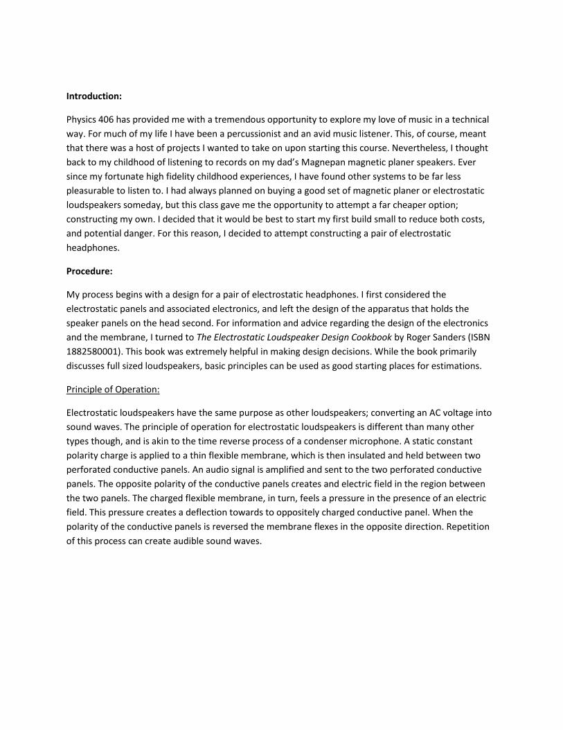
effects of baffled vs open air testing. Here is a picture of the completed electrostatic panels sitting
between the wooden rings:
Construction:
The electrical components were soldered on a section of perforated circuit board in accordance with the
schematic shown above. Voltages were measured across C1 to verify estimated values were
approximately reached. We also measured the AC flutter across C1, as well as the current values at the
ground points which were all on the order expected.

Note, the bias voltage transformer is not pictured here. The two visible transformers are the Edcor
GXSE5-8-5.5K.
Confident that the electronics were working to within reasonable margin, I progressed to physical
assembly of the electrostatic panels. I Cut and glued the wood into rectangular rings that would later
make up the frame. The more complex part of the construction was the electrostatic panels themselves.
The panels needed to be made in a way so that the membrane was under tension, insulated from the
stators, and a lead was present that could supply the bias voltage.
First, powdered graphite was rubbed into the Mylar using cotton balls
In the finished product, it can be noted that the graphite impregnated Mylar is darker than the
untreated:
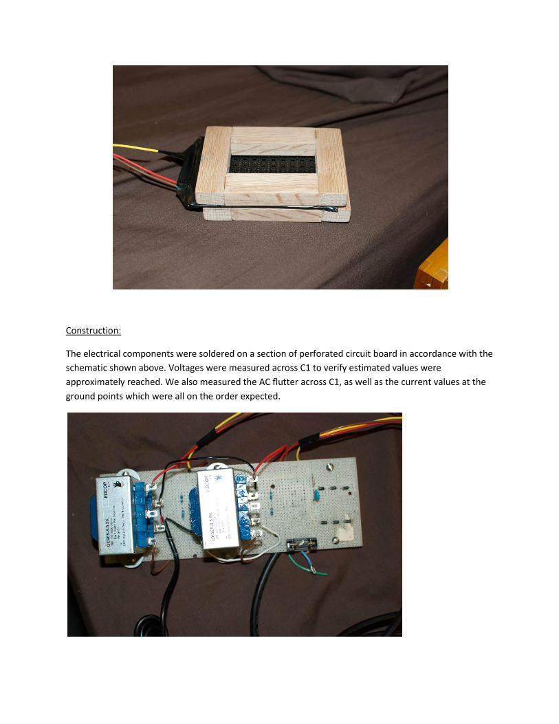
The treated Mylar was then stretched over an embroidery ring:
While this does not provide the necessary tension, it begins applying tension to the mylar while the
insulating rings are glued on. The Mylar will be heat treated later induce shrinking, and add tension to
the system.
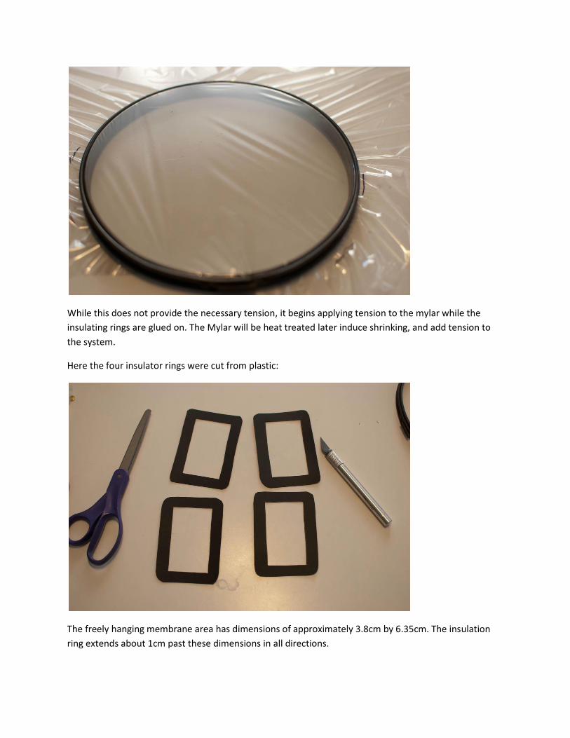
Here the four insulator rings were cut from plastic:
The freely hanging membrane area has dimensions of approximately 3.8cm by 6.35cm. The insulation
ring extends about 1cm past these dimensions in all directions.

Copper tape was then glued to the inside of two of the insulating rings. These sides would later be
applied to the treated side of the Mylar:
Both pairs of insulator rings were then glued to the Mylar, and allowed to dry:

After the Insulator rings were set, the perforated panels were cut to the same size and glued to the
outside of the insulator rings. The edges of the Mylar were then cut, and all edges were covered with
electrical tape.
The completed panels were then wired into the circuit in accord with the schematic listed above:
The construction was now complete. Unfortunately, in the week that elapsed between construction and
testing, the glue that held the Mylar under tension began to release its hold. In response, I remade the
panels, this time applying more glue, carefully cleaning all surfaces, and scouring mating surfaces to
attempt to give a better grip. However, the same effect occurred, and tension was largely lost in the
panels. Due to time constraints, we decided to test the panels as they were and construction of a third
set of panels with different glues has been delayed.
Data Collection:
Proof of operation was achieved using a digital sine wave function generator, 50 watt mono amp (of
Professor Errede’s construction) and a digital oscilloscope. Belo is a picture of the first test:

The blue signal on the oscilloscope is the reference signal from the sine wave generator and the yellow
is the voltage output from the Edcor audio transformers. Both channels produced audible sound with
this setup.
To obtain more objective data, we utilized an HP frequency spectrum analyzer. The frequency spectrum
analyzer created a white noise signal that was then amplified using the same 50 watt audio power amp.
Data was collected for white noise produced in several frequency regions: 0-1KHz, 0-2KHz, 0-5KHz, 0-
10KHz, 0-20KHz, 0-50KHz, and 0-100KHz. The sound outputs in these regions were measured with the
Knowles Electronics FG-23329 condenser microphone and graphed log-log and semi-log plots using
Matlab script courtesy of Professor Errede. Measurements were taken for the right and left channels
with the panels suspended in free air, as well as the noise levels in the room.
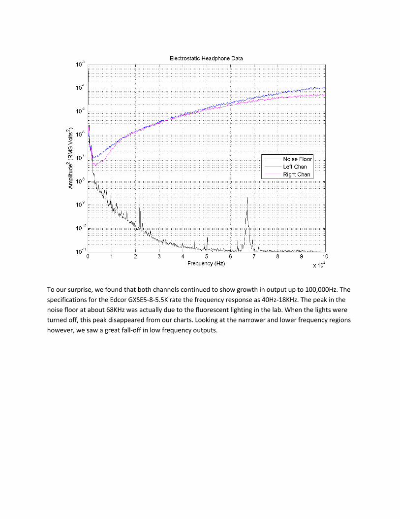
To our surprise, we found that both channels continued to show growth in output up to 100,000Hz. The
specifications for the Edcor GXSE5-8-5.5K rate the frequency response as 40Hz-18KHz. The peak in the
noise floor at about 68KHz was actually due to the fluorescent lighting in the lab. When the lights were
turned off, this peak disappeared from our charts. Looking at the narrower and lower frequency regions
however, we saw a great fall-off in low frequency outputs.


In the 0-10KHz region, we see a curve relatively similar in shape to the 0-100KHz region. The 0-1KHz plot
shows that outputs from the headphones only stay at about 1 order of magnitude above noise levels for
most of the region. It is readily apparent that the right channel has better responses at lower frequency.
This comes as no surprise when visually inspecting the panels, because the left panel membrane held far
less tension than the right, and was more visually rippled. We attribute the poor frequency response to
the loss of tension as well as phase cancellation. The effects of phase cancellation will be reduced
greatly when the user wears the completed headphones on their head, as the head will acoustically
insulate one side of the panels from the other. We considered completing the final construction despite
the loss in membrane tension to measure frequency responses in the completed product, but time
constraints did not allow this. Instead, we constructed a baffle using a spare box and foam that were in
the lab. We had time to collect data for only one channel while using the baffle, so we used the right
channel, as it had a better frequency response to start with. Below are the 100KHz, 10KHz, and 1KHz
plots

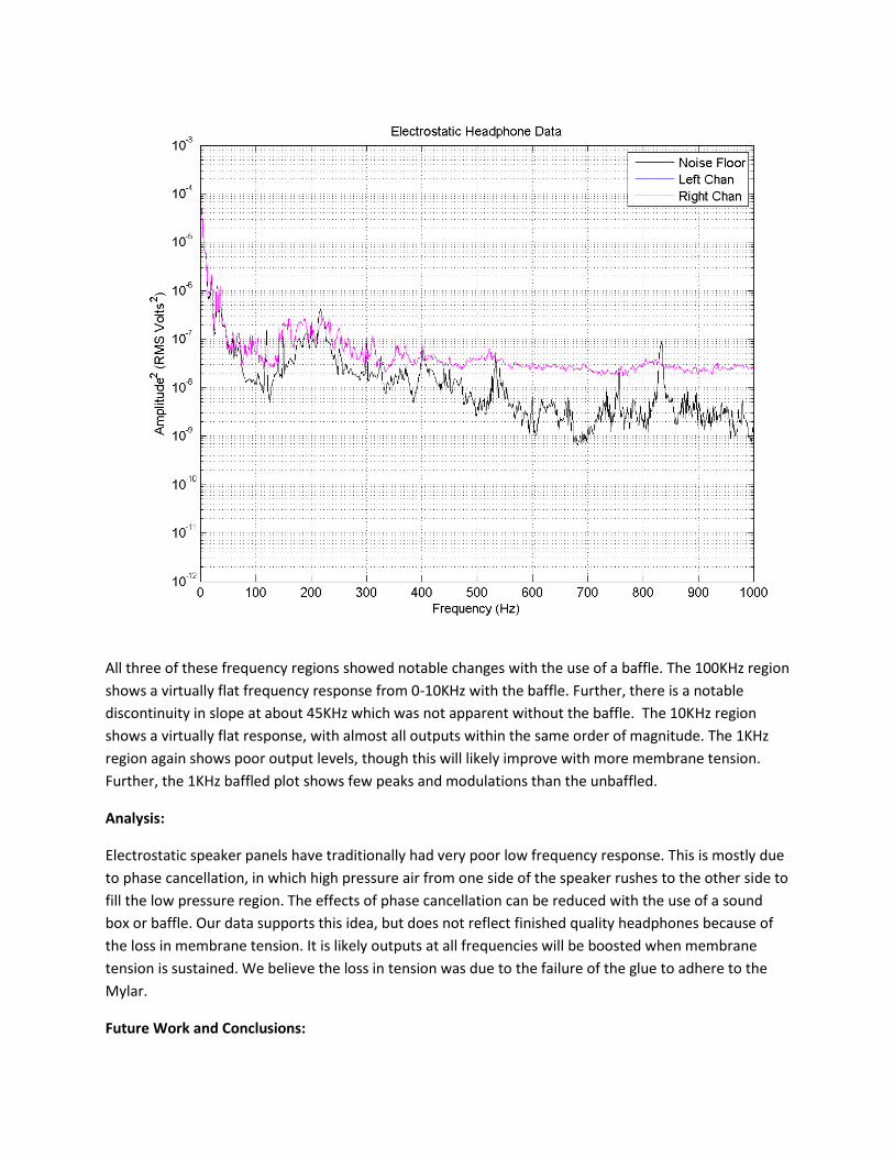
All three of these frequency regions showed notable changes with the use of a baffle. The 100KHz region
shows a virtually flat frequency response from 0-10KHz with the baffle. Further, there is a notable
discontinuity in slope at about 45KHz which was not apparent without the baffle. The 10KHz region
shows a virtually flat response, with almost all outputs within the same order of magnitude. The 1KHz
region again shows poor output levels, though this will likely improve with more membrane tension.
Further, the 1KHz baffled plot shows few peaks and modulations than the unbaffled.
Analysis:
Electrostatic speaker panels have traditionally had very poor low frequency response. This is mostly due
to phase cancellation, in which high pressure air from one side of the speaker rushes to the other side to
fill the low pressure region. The effects of phase cancellation can be reduced with the use of a sound
box or baffle. Our data supports this idea, but does not reflect finished quality headphones because of
the loss in membrane tension. It is likely outputs at all frequencies will be boosted when membrane
tension is sustained. We believe the loss in tension was due to the failure of the glue to adhere to the
Mylar.
Future Work and Conclusions:
I intend on making more electrostatic panels trying various glue types and tensioning techniques. Some
commercial builders of electrostatic speakers make curved panels that are only tensioned longitudinally.
I will first attempt to create panels that hold tension along two dimensions, and possibly try panels that
are tensioned along one dimension. The electronics that I have created allow me to experiment with
many different panel and enclosure designs.
While I did not complete headphone drivers that worked to the degree that I had intended, I believe this
was largely due to time constraints. My knowledge in this area has grown tremendously, and has given
me a project that is adaptable, modifiable, and will continue to be an area of interest for me. I also plan
to attempt constructing a full sized pair of electrostatic speakers when I have gained more experience in
this area. Lastly, I will consider my build to be a remarkable success if I can get the membrane to hold
tension. This is because the total cost of this build is largely invested in transformers and other electrical
supplies, totaled a little over $100. The cheapest set of commercially available electrostatic headphones
I have found cost over $500, and some brands sell for thousands.
Special Thanks:
My thanks go out first to Professor Stephen Errede, whose guidance and expertise have given me the
tools to continue pursuing and area that interests me greatly. I would not have been able to complete
my project without his guidance, lab equipment, and generous help. Secondly, I would like to
acknowledge the work of Roger Sanders and his book, Electrostatic Loudspeaker Design Cookbook.
While there is a great deal of physics involved in the construction of electrostatic speakers, theoretical
operation does not always match actual construction. For this reason, experience is needed to
understand hat methods have been effective in the past. Sanders’ book is a great source of both the
theoretical foundation for, as well as the tried and true methods of the construction of electrostatic
loudspeakers.