electroscan owner's manual - raritan...
TRANSCRIPT
1
Models EST12, EST24 and EST32Installation and Maintenance Instructions
THE FOLLOWING ARE CAUTIONARY STATEMENTS THAT MUST BE READ AND FOLLOWEDDURING BOTH INSTALLATION AND OPERATION
WARNING: Raritan Engineering Company, Inc. recommends that a qualified person or electrician install thisproduct. Equipment damage, injury to personnel or death could result from improper installation.Raritan Engineering Company, Inc. accepts no responsibility or liability for damage to equipment,or injury or death to personnel that may result from improper installation or operation of thisproduct.
WARNING: HAZARD OF SHOCK AND FIRE - Always use recommended fuse/circuit breaker and wire size.
WARNING: HAZARD OF FLOODING - Always shut off seacocks before leaving boat unattended.Double clamp all hose fittings below the waterline, check hose clamps frequently for integrity.
WARNING: The electro scan operates on an Electrochemical principle. Introduction of any substance other thansalt water, human waste, Raritan Concentrate, Raritan C.P. or toilet tissue may cause heat build upand extensive damage. If any other substance is introduced by accident, the electro scan must notbe turned on until entire system is flushed out with water.
electro scan™ is a U. S. Coast Guard Certified Type I Marine Sanitation Device for use on inspected anduninspected vessels 65 feet (19.7 Meters) and under. It must be operated within areas that are not declareda Federal No Discharge Zone (NDZ) by the U.S. Environmental Protection Agency (EPA). This is applicablefor all U.S. territorial waters inside the three mile limit. Other countries - check with local authorities.
electro scan is designed for recreational use and accommodates most marine toilets* it can be used with oneor, in some cases, two toilets. The electro scan is available in 12, 24 or 32 V DC.
The system consists of a Control Unit, LCD Display, System Status Panel and Treatment Tank.
A salt feed system (optional) must be utilized if operating in fresh or brackish water. Pleasesee Page 7 for complete details on Salt Feed Options.
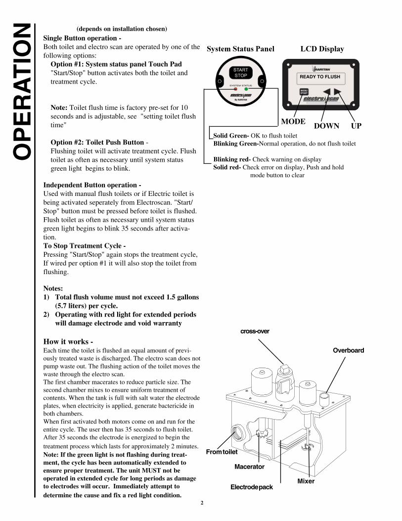
electro scan with control optional salt feed systems
2 gallon tank
4 gallon tank
* for use with the VacuFlush® marine toilet manufactured by Sealand Technology, Inc., (See Application note L286)VacuFlush® is a registered trademark of Sealand Technology, Inc. electroscan™ is a trademark of Raritan Engineering Co., Inc., patent pending
��
2
OP
ER
AT
ION (depends on installation chosen)
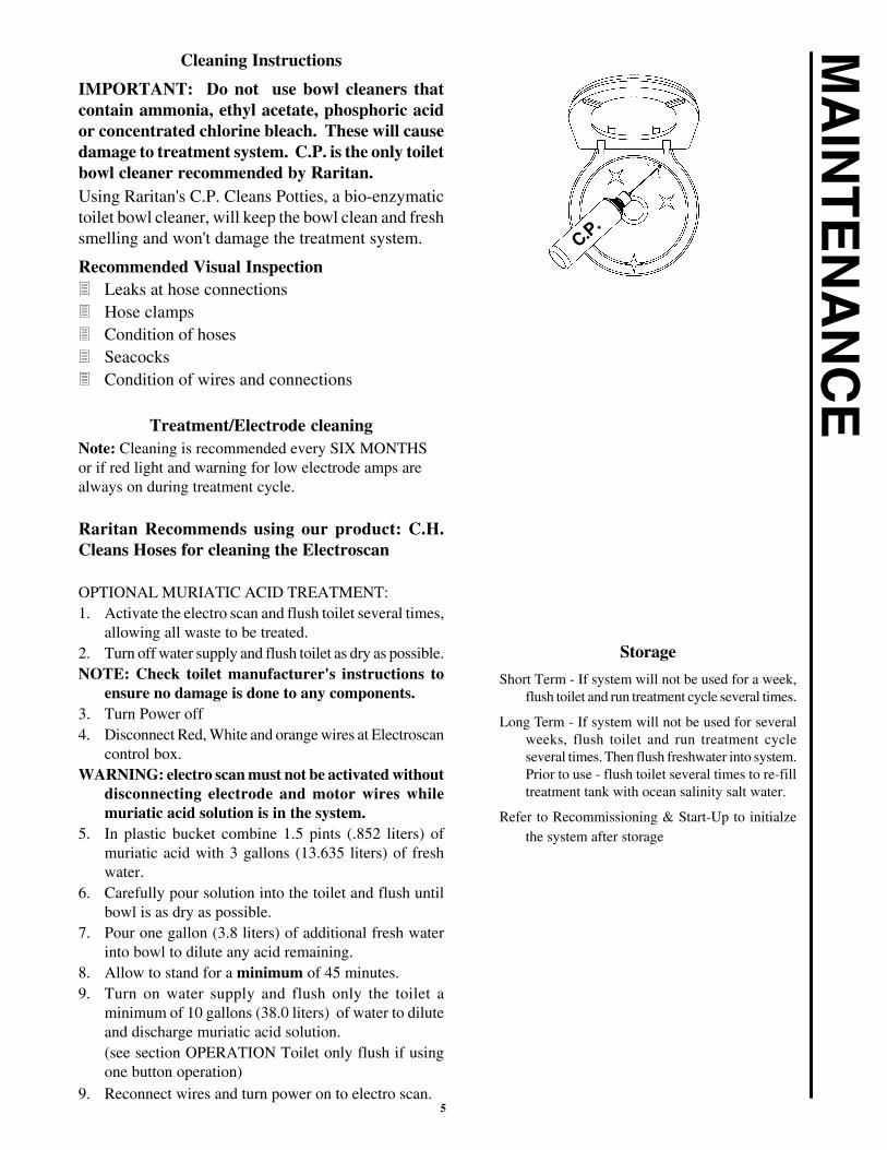
Single Button operation -Both toilet and electro scan are operated by one of thefollowing options:
Option #1: System status panel Touch Pad"Start/Stop" button activates both the toilet andtreatment cycle.
Note: Toilet flush time is factory pre-set for 10seconds and is adjustable, see "setting toilet flushtime"
Option #2: Toilet Push Button -Flushing toilet will activate treatment cycle. Flushtoilet as often as necessary until system statusgreen light begins to blink.
Independent Button operation -Used with manual flush toilets or if Electric toilet isbeing activated seperately from Electroscan. "Start/Stop" button must be pressed before toilet is flushed.Flush toilet as often as necessary until system statusgreen light begins to blink 35 seconds after activa-tion.To Stop Treatment Cycle -Pressing "Start/Stop" again stops the treatment cycle,If wired per option #1 it will also stop the toilet fromflushing.
Notes:1) Total flush volume must not exceed 1.5 gallons
(5.7 liters) per cycle.2) Operating with red light for extended periods
will damage electrode and void warranty
How it works -Each time the toilet is flushed an equal amount of previ-ously treated waste is discharged. The electro scan does notpump waste out. The flushing action of the toilet moves thewaste through the electro scan.The first chamber macerates to reduce particle size. Thesecond chamber mixes to ensure uniform treatment ofcontents. When the tank is full with salt water the electrodeplates, when electricity is applied, generate bactericide inboth chambers.When first activated both motors come on and run for theentire cycle. The user then has 35 seconds to flush toilet.After 35 seconds the electrode is energized to begin thetreatment process which lasts for approximately 2 minutes.Note: If the green light is not flashing during treat-ment, the cycle has been automatically extended toensure proper treatment. The unit MUST not beoperated in extended cycle for long periods as damageto electrodes will occur. Immediately attempt todetermine the cause and fix a red light condition.
Overboard
Electrode pack
From toilet
cross-over
Mixer
Macerator
Solid Green- OK to flush toiletBlinking Green-Normal operation, do not flush toilet
Blinking red- Check warning on displaySolid red- Check error on display, Push and hold
mode button to clear
MODE DOWN UP
����������
������������ ���� ������
READY TO FLUSH

3
The electro scan has four basic components:� System Status Panel - Begins treatment cycle
and if wired flushes an electric toilet at the sametime.
� Control Unit – Serves as the system’s centralcontrol. The unit contains three boards: Main(contains the power and logic components),Microprocessor/Memory (contains systemprogram and stores operational data) and I/O(where connections are made for accessories).
� Treatment Tank - Consists of two chambers andelectrode pack that temporarily converts saltwaterinto a powerful bactericide for the duration of thetreatment cycle.
� LCD Display – Provides information duringtreatment cycle and summary of historicaldata. Also contains RESET button if system erroroccurs.
Setting time and date on LCD Display:���Scroll to "time screen" using < and > keys when
unit is not in cycle.���Hold “mode” button until digits flash���use < and > button to set hour in military time���Push “mode" again for next digits (minutes)���Use < and > to set minutes���Repeat above until time and date are set���Use < or > to move to next screen when no
digits are flashing.
Setting toilet Flush time on LCD Display:� Scroll to "flushtime" screen using < and > keys
when unit is not in cycle.� Hold ‘mode” button until digits flash� Use <or > keys to set time in seconds for toilet 1� Repeat above for toilet 2 (flushtime 2).
Toilet only flush:Use only for servicing, storage or recommission-ing. It is illegal to discharge untreated sewage inU.S. waters.� Scroll to Flushtime (1 or 2) screen using < or >
keys when unit is not in cycle.� Hold "mode" button and press < or > key.� Toilet will flush for set time.
��������
RARITAN
LST / MC II
CONTROL UNIT
OP
ER
AT
ION
��� ������
TIME 00:00:00DATE: 01/01/01
���������
��� ���� ������
���������
FLUSHTIME 105

4
Most operation and troubleshooting information is displayed on the LCD display panel.Following is the description of display screens and what they mean.
RED LED blinks for warning and is solid for errors
OP
ER
AT
ION
Treatment terminates in ERROR condition for reasons listed below. To clear error conditionafter corrective action is taken, hold mode/reset button on display for four seconds.
��������� ����� ������������� ������������������������������������� �������������������� ������������������������������������������ �� �����������������
TIME 00:00:00DATE: 01/01/00
FLUSHTIME 105
FLUSHTIME 210
NUMBER OF CYCLES00100
NUMBER OF RESETS00
CYCLE W/O LST000
LOW AMP 14-18000
LOW AMPS 7-14000
LOW AMP SHUTDOWN000
LOW VOLTS < 90%05
LOW VOLT < 83%01
MIN TEMPERATURE20
LOW VOLT SHUTDOWN05
MAX TEMPERATURE90
����� ������������� � �� ������!��
Previous cycle ended normally Ready for next cycle
Previous cycle completed with low voltage, Ready for next cycle,low voltage should be corrected
Previous cycle completed with low electrode amps, Ready fornext cycle, low amps should be corrected
Unit is in pretreatment cycle after start, voltage displayed,
Unit goes to treatment cycle after pretreatment for 120 seconds,voltage and amps are displayed alternately.
During the treatment cycle if electrode amps drop below 14,Warning is displayed, and cycle is extended up to 240 seconds
During the entire cycle if voltage drops below 89% of full batteryvoltage, warning is displayed, cycle continues
READY TO FLUSH
****WARNING****VOLTAGE LOW
**PRETREATMENT**VOLTAGE= 100%
***TREATMENT***VOLTAGE= 100%
***TREATMENT***AMPS = 15
****WARNING****AMP = 10
****WARNING***VOLTAGE< 87%
****WARNING**** AMPS< 14
Voltage was less that 83% of full voltage during the cycle; checkbattery , connections and wire sizes.
*****ERROR****LOW VOLTAGE
*****ERROR*****LOW ELECTROD AMP
*****ERROR*****MIX MOTOR OVERLD
*****ERROR*****MaC MOTOR OVERLD
*****ERROR*****ELECTROD OVERLD
*****ERROR*****POS FUSE BLOWN
Electrode amps were lower than 7 amps, check salt, clean electrodewith acid treatment, check all connections.
Mixer motor amps were high, Check for foreign material in mixerchamber, seal leaks, motor shortsMacerator motor amps were high, Check for foreign material inmacerator chamber, seal leaks, and motor shortsElectrode amps were higher than 28 amps during fresh wateroperation, check for excessive salt, shorted electrode, wiring.Positive/Negative fuse on I/O connection board is blown due tosome external short, check toilet solenoid type, wiring to solenoid.Solenoid (relay) to toilet must be isolated coil type or Raritansolenoid.
*****ERROR*****NEG FUSE BLOWN
5
MA
INT
EN
AN
CE
Cleaning Instructions
IMPORTANT: Do not use bowl cleaners thatcontain ammonia, ethyl acetate, phosphoric acidor concentrated chlorine bleach. These will causedamage to treatment system. C.P. is the only toiletbowl cleaner recommended by Raritan.Using Raritan's C.P. Cleans Potties, a bio-enzymatictoilet bowl cleaner, will keep the bowl clean and freshsmelling and won't damage the treatment system.
Recommended Visual Inspection� Leaks at hose connections� Hose clamps� Condition of hoses� Seacocks� Condition of wires and connections
Treatment/Electrode cleaningNote: Cleaning is recommended every SIX MONTHSor if red light and warning for low electrode amps arealways on during treatment cycle.
Raritan Recommends using our product: C.H.Cleans Hoses for cleaning the Electroscan
OPTIONAL MURIATIC ACID TREATMENT:1. Activate the electro scan and flush toilet several times,
allowing all waste to be treated.2. Turn off water supply and flush toilet as dry as possible.NOTE: Check toilet manufacturer's instructions to
ensure no damage is done to any components.3. Turn Power off4. Disconnect Red, White and orange wires at Electroscan
control box.WARNING: electro scan must not be activated without
disconnecting electrode and motor wires whilemuriatic acid solution is in the system.
5. In plastic bucket combine 1.5 pints (.852 liters) ofmuriatic acid with 3 gallons (13.635 liters) of freshwater.
6. Carefully pour solution into the toilet and flush untilbowl is as dry as possible.
7. Pour one gallon (3.8 liters) of additional fresh waterinto bowl to dilute any acid remaining.
8. Allow to stand for a minimum of 45 minutes.9. Turn on water supply and flush only the toilet a
minimum of 10 gallons (38.0 liters) of water to diluteand discharge muriatic acid solution.(see section OPERATION Toilet only flush if usingone button operation)
9. Reconnect wires and turn power on to electro scan.
C.P.
Storage
Short Term - If system will not be used for a week,flush toilet and run treatment cycle several times.
Long Term - If system will not be used for severalweeks, flush toilet and run treatment cycleseveral times. Then flush freshwater into system.Prior to use - flush toilet several times to re-filltreatment tank with ocean salinity salt water.
Refer to Recommissioning & Start-Up to initialzethe system after storage

6
WIN
TE
RIZ
ING IMPORTANT
• Improper winter lay up is a major cause of failuredue to freezing or buildup.
Steps1. Flush toilet and activate electro scan several times to
clean out hoses and tank.
2. Turn off water supply and flush toilet as dry as possible.
NOTE: Check toilet manufacturer's instructions toensure no damage is done to any components.
3. Turn off power and disconnect wires to electro scan.
4. Close seacocks.
5. Slowly open cross-over plug.
Caution: Open plug slowly as unit may be under pressure.
5. Using a pump and 3/8" tube, remove water from eachside of partition in treatment tank through crossoverplug.
6. Disconnect and drain hoses.
Recommissioning & Start-Up
1. Reconnect hoses and open seacocks.
2. Reconnect wires and turn power on.
NOTE: electro scan treatment tank must be full with seawater salinity water before activating a cycle.
3. Flush toilet using one of the following methods to fillthe treatment tank with salt water.
• Scroll to Flushtime (1 or 2) screen using < or >keys when unit is not in cycle. Hold "mode" buttonand press < or > key. Toilet will flush for set time.
• Separate operation - flush toilet allowing threegallons of water to pass into electro scan.
• if toilet operates electro scan - you must disconnectpower from electro scan while flushing to allowthree gallons (13.6 liters) of water to pass intoelectro scan.
NOTE: In fresh and brackish water operation, salt contentof treatment tank must be ocean water salinity priorto using unit for treatment. Ocean water salinity is3% or approximately four ounces of salt to onegallon of water (32g/liter).
4. Inspect all connections for leaks.
5. System is ready for use.
Cross-over Plug
7
SP
EC
IFIC
AT
ION
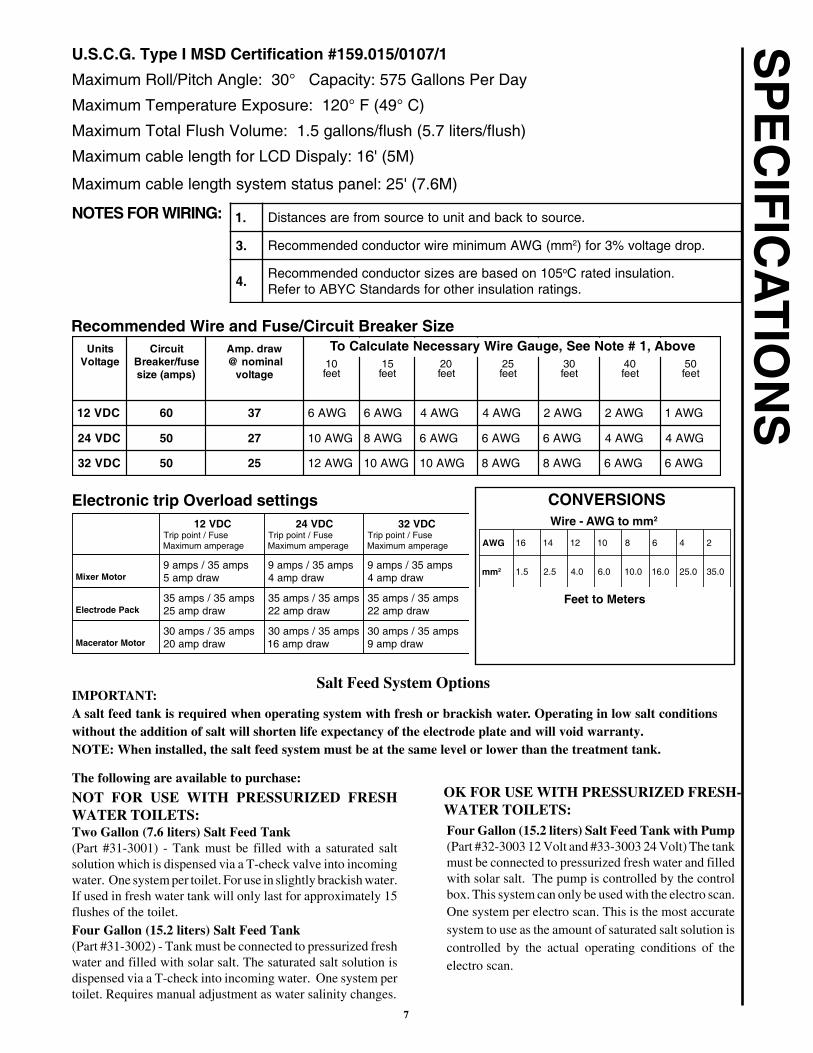
SU.S.C.G. Type I MSD Certification #159.015/0107/1
Maximum Roll/Pitch Angle: 30° Capacity: 575 Gallons Per Day
Maximum Temperature Exposure: 120° F (49° C)
Maximum Total Flush Volume: 1.5 gallons/flush (5.7 liters/flush)
Maximum cable length for LCD Dispaly: 16' (5M)
Maximum cable length system status panel: 25' (7.6M)
CONVERSIONSWire - AWG to mm2
Feet to Meters
NOTES FOR WIRING:
Recommended Wire and Fuse/Circuit Breaker Size
Electronic trip Overload settings
IMPORTANT:A salt feed tank is required when operating system with fresh or brackish water. Operating in low salt conditionswithout the addition of salt will shorten life expectancy of the electrode plate and will void warranty.NOTE: When installed, the salt feed system must be at the same level or lower than the treatment tank.
The following are available to purchase:
NOT FOR USE WITH PRESSURIZED FRESHWATER TOILETS:Two Gallon (7.6 liters) Salt Feed Tank(Part #31-3001) - Tank must be filled with a saturated saltsolution which is dispensed via a T-check valve into incomingwater. One system per toilet. For use in slightly brackish water.If used in fresh water tank will only last for approximately 15flushes of the toilet.Four Gallon (15.2 liters) Salt Feed Tank(Part #31-3002) - Tank must be connected to pressurized freshwater and filled with solar salt. The saturated salt solution isdispensed via a T-check into incoming water. One system pertoilet. Requires manual adjustment as water salinity changes.
Four Gallon (15.2 liters) Salt Feed Tank with Pump(Part #32-3003 12 Volt and #33-3003 24 Volt) The tankmust be connected to pressurized fresh water and filledwith solar salt. The pump is controlled by the controlbox. This system can only be used with the electro scan.One system per electro scan. This is the most accuratesystem to use as the amount of saturated salt solution iscontrolled by the actual operating conditions of theelectro scan.
Salt Feed System Options
OK FOR USE WITH PRESSURIZED FRESH-WATER TOILETS:
.1 .ecruosotkcabdnatinuotecruosmorferasecnatsiD
.3 mm(GWAmuminimeriwrotcudnocdednemmoceR 2 .pordegatlov%3rof)
.4501nodesaberasezisrotcudnocdednemmoceR o .noitalusnidetarC
.sgnitarnoitalusnirehtorofsdradnatSCYBAotrefeR
stinUegatloV
tiucriCesuf/rekaerB)spma(ezis
ward.pmAlanimon@
egatlov01teef
51teef
02teef
52teef
03teef
04teef
05teef
CDV21 06 73 GWA6 GWA6 GWA4 GWA4 GWA2 GWA2 GWA1
CDV42 05 72 GWA01 GWA8 GWA6 GWA6 GWA6 GWA4 GWA4
CDV23 05 52 GWA21 GWA01 GWA01 GWA8 GWA8 GWA6 GWA6
CDV21esuF/tnioppirT
egarepmamumixaM
CDV42esuF/tnioppirT
egarepmamumixaM
CDV23esuF/tnioppirT
egarepmamumixaM
rotoMrexiMspma53/spma9
wardpma5spma53/spma9
wardpma4spma53/spma9
wardpma4
kcaPedortcelEspma53/spma53
wardpma52spma53/spma53
wardpma22spma53/spma53
wardpma22
rotoMrotarecaMspma53/spma03
wardpma02spma53/spma03
wardpma61spma53/spma03
wardpma9
GWA 61 41 21 01 8 6 4 2
mm 2 5.1 5.2 0.4 0.6 0.01 0.61 0.52 0.53
To Calculate Necessary Wire Gauge, See Note # 1, Above
8
INS
TAL
LA
TIO
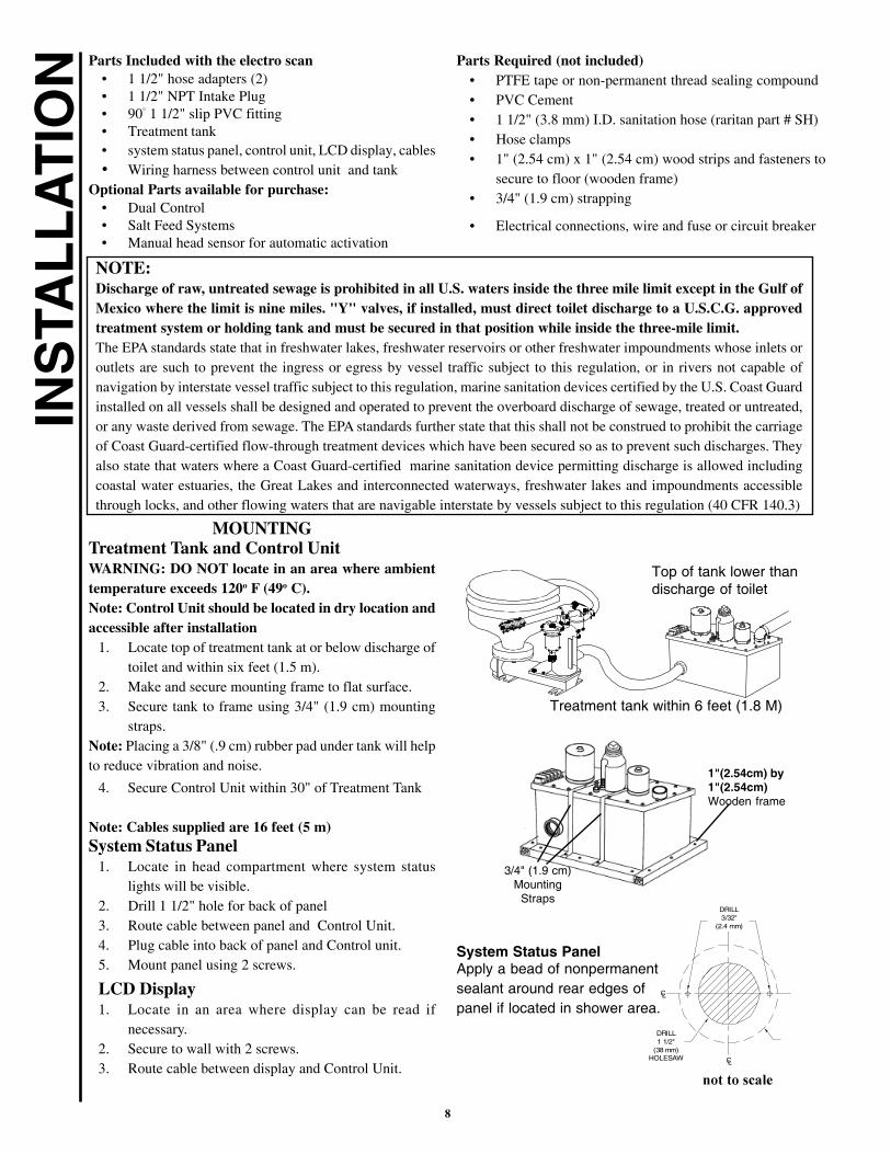
N Parts Included with the electro scan• 1 1/2" hose adapters (2)• 1 1/2" NPT Intake Plug• 90° 1 1/2" slip PVC fitting• Treatment tank• system status panel, control unit, LCD display, cables� Wiring harness between control unit and tank
Optional Parts available for purchase:• Dual Control• Salt Feed Systems• Manual head sensor for automatic activation
MOUNTINGTreatment Tank and Control UnitWARNING: DO NOT locate in an area where ambienttemperature exceeds 120o F (49o C).Note: Control Unit should be located in dry location andaccessible after installation
1. Locate top of treatment tank at or below discharge oftoilet and within six feet (1.5 m).
2. Make and secure mounting frame to flat surface.3. Secure tank to frame using 3/4" (1.9 cm) mounting
straps.Note: Placing a 3/8" (.9 cm) rubber pad under tank will helpto reduce vibration and noise.
4. Secure Control Unit within 30" of Treatment Tank
Note: Cables supplied are 16 feet (5 m)System Status Panel
1. Locate in head compartment where system statuslights will be visible.
2. Drill 1 1/2" hole for back of panel3. Route cable between panel and Control Unit.4. Plug cable into back of panel and Control unit.5. Mount panel using 2 screws.
LCD Display1. Locate in an area where display can be read if
necessary.2. Secure to wall with 2 screws.3. Route cable between display and Control Unit.
Treatment tank within 6 feet (1.8 M)
Top of tank lower thandischarge of toilet
3/4" (1.9 cm)Mounting
Straps
1"(2.54cm) by1"(2.54cm)Wooden frame
NOTE:Discharge of raw, untreated sewage is prohibited in all U.S. waters inside the three mile limit except in the Gulf ofMexico where the limit is nine miles. "Y" valves, if installed, must direct toilet discharge to a U.S.C.G. approvedtreatment system or holding tank and must be secured in that position while inside the three-mile limit.The EPA standards state that in freshwater lakes, freshwater reservoirs or other freshwater impoundments whose inlets oroutlets are such to prevent the ingress or egress by vessel traffic subject to this regulation, or in rivers not capable ofnavigation by interstate vessel traffic subject to this regulation, marine sanitation devices certified by the U.S. Coast Guardinstalled on all vessels shall be designed and operated to prevent the overboard discharge of sewage, treated or untreated,or any waste derived from sewage. The EPA standards further state that this shall not be construed to prohibit the carriageof Coast Guard-certified flow-through treatment devices which have been secured so as to prevent such discharges. Theyalso state that waters where a Coast Guard-certified marine sanitation device permitting discharge is allowed includingcoastal water estuaries, the Great Lakes and interconnected waterways, freshwater lakes and impoundments accessiblethrough locks, and other flowing waters that are navigable interstate by vessels subject to this regulation (40 CFR 140.3)
Parts Required (not included)• PTFE tape or non-permanent thread sealing compound• PVC Cement• 1 1/2" (3.8 mm) I.D. sanitation hose (raritan part # SH)• Hose clamps• 1" (2.54 cm) x 1" (2.54 cm) wood strips and fasteners to
secure to floor (wooden frame)• 3/4" (1.9 cm) strapping
• Electrical connections, wire and fuse or circuit breaker
DRILL3/32"
(2.4 mm)
DRILL1 1/2"
(38 mm)HOLESAW
CONTROL INDICATOR
PANEL OUTLINE
CL
CL
CONTROL INDICATOR PANELMOUNTING
System Status PanelApply a bead of nonpermanentsealant around rear edges ofpanel if located in shower area.
������� ���

9
INS
TAL
LA
TIO
N \ W
IRIN
GPLUMBING
WARNING:
• All installations made below the waterline MUST beprotected by installing vented loops in proper location
• Always double-clamp fittings below waterline
• Do Not use metal fittings
NOTE: Use PTFE tape or non-permanent thread sealingcompound on threaded PVC fittings and connections. Avoidlow areas in hose that would allow untreated waste to collect.
1. Connect discharge of toilet to one inlet port.
2. Insert plug or second toilet discharge into other inlet port.
3. Determine position and glue discharge elbow to top oftank using PVC cement.
4. Connect discharge hose from elbow to thru hull fitting.
WIRINGWARNING: Hazard of Shock and Fire• Always use proper wire, wire connectors and fuse/
circuit breaker. See Specification Chart.• Secure wire properly.• Do not connect other appliances to electro scan circuit.• Make sure power is off before proceeding.
• Improper wiring can damage the Circuit Board andvoid warranty.
• Fuses must be replaced with the same type to maintainignition protection
Treatment Unit1. Determine proper wire size from wire chart on
specifications page.2. Run supply wire from source Positive (POS) to control unit
and Negative (NEG) terminals on Treatment tank.3. Install terminal protector on positive connection4. Fuse or circuit breaker must be installed between source
and electro scan on positive wire.NOTE: Future access to control box is imperative. If unit is
installed in an area where access will be difficult contactRaritan for instructions on mounting the control box fordistance more than two feet.
System Status Panel1. Connect cable from System Status Panel to panel 1 jack on
Control Unit.2. Secure cable strain relief.3. Follow same procedure for panel 2 if dual installation.
LCD Display1. Connect cable from LCD Display to display jack on the
Control Unit.2. Secure cable strain relief.
Discharge from toilet:each side if dual installationone side in single installation
Discharge from electroscan to thru-hull
������
"#���
�����
�����
Red
��� ������
������
�����
�����
Red
���������� ������ ��
���� �������
����������
��������������

10
INS
TAL
LA
TIO
N \
WIR
ING Single Button operation -
Both toilet and electro scan are operated by one of thefollowing options:
Option #1:NOTES:• Use only a solenoid/relay with an isolated coil Raritan
part number CDS* (*specify voltage)• Connect only the solenoid/relay (CDS) coil to toilet 1
or 2 quick connect. DO NOT connect toilet negativeand positive directly to outputs.
• Do Not connect switches or any other components tothe Toilet 1 or 2 outputs or the CDS.
System status panel"Start/Stop" button activates both the toilet and treatmentcycle.Note: Toilet flush time is factory pre-set at approxi-mately 10 seconds and is adjustable.1. Determine proper wire size from toilet manufacturer.2. Connect wire from lug not marked "BAT" on the CDS
to toilet positive.3. From top posts of CDS connect positive and negative
to toilet 1 or 2 outputs on control box utilizing .4. Connect wire from positive source to Raritan CDS
(solenoid/relay) post marked "BAT" utilizing properfuse in positive line.
5. When "Start/Stop" button is pressed both toilet andelectro scan will activate. Toilet flush time is controlledby Control box and can be adjusted - factory preset isfor 10 seconds.
Option #2:Toilet Push Button -Flushing toilet will also activate treatment cycle.
Toilet Push Button
1. Determine proper wire size from toilet manufacturer.2. Connect wire from lug not marked "BAT" on the CDS
to toilet positive.3. Connect wire from top post of CDS to one of the ext.
trig. (external trigger) outputs.4. Connect wire from positive source to Raritan CDS
(solenoid/relay) post marked "BAT" utilizing properfuse in positive line.
5. When Toilet Push Button is pressed both toilet and
electro scan will activate.
EXT TRIG
BatteryFUSE(toilet)
PBS
Toilet 1
Toilet 1
FUSE(toilet)
BatteryGnd
HEAD 1
To small terminalson CDS* for secondtoilet. Wiring for sec-ond toilet is identical towiring for first toilet.
Wiring Salt feed pump
Salt Pump
�� ����������� �� ���������� ���� �������
�� ����� ����� �� ������� ��� !�����"#� ���$� �"�
To point "A" ofwiring forToilet 2
HEAD 2
Point "A"
� �
� �
RaritanCDS*
Gnd
��������� ����!
�
Wiring for second CDS* and toilet is identical to wiring for first CDS* and toilet.
��������� ����!
����������
�
NEG

11
Head1+
EXT TRIG
Yellow
Atlantes ControlBoard
To otherAtlantes Toilet(purple pigtail)
Purple Atlantescontrol board
To otherAtlantes Toilet(yellow pigtail)
INS
TAL
LA
TIO
N \ W
IRIN
G��������
��� ������
���
���
�����
�����������
�����������
���
�������
����
���
��������������
����
����
������
� �
��
�������
���
�������
RARITAN
SALT FD + EXT TRIGNEG
NEG
NEG
NEG EXT TRIG
MAN IN
MAN IN
HEAD 2 +
HEAD 1 +
AUX +
HD POSHD NEGFUSES
��������
��� ������
���
���
����������������
�����������
���
����������
�
���
������������������
����������
� �
��
�������
���
�������
RARITAN
AUX +
HEAD 2 +
HEAD 1 +
SALT FD +
NEG
NEG
NEG
NEG
MAN IN
MAN IN
EXT TRIG
EXT TRIG
FUSESHD NEG HD POS
To "TO LST"on second
Atlantes toilet
To "FROM LST"on second Atlantestoilet
Wiring Atlantes to Electro Scan
�� ����� ����� �� �����%���� ������%����&�� ��� � ��� ��� �"�'����$��$� �"
������$%����$&
$��������������������$'����$( $��������������
������$'����$(
������$%����$&
NOTE: If installation is done with RaritanAtlantes toilet the flush time adjustment on theLCD display must be set to one second.
�� ����������� �� �����%�&�� ��� � ��� ��� %������� ���� ������
EXT TRIG
FROM LST "TO LST"
12
� ������������
� ���� ������������ ����
� �� ���� ������������ ������������������������� ���� �������������
� ������������ �����������
� �������������� ��������� ������������������������������ ����
� )*�+,� ���� ���� ��� �����������������������!������� ��������������������������������������� ������������������������������ ���� �����������"
TR
OU
BL
ES
HO
OT
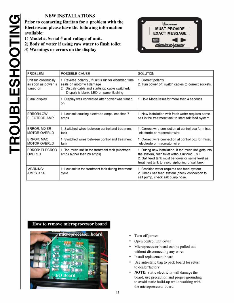
ING Prior to contacting Raritan for a problem with the
Electroscan please have the following informationavailable:1) Model #, Serial # and voltage of unit.2) Body of water if using raw water to flush toilet3) Warnings or errors on the display
NEW INSTALLATIONS
��������� ������ ����
������� ������ �� �� ���
��������������������������������
��������
������������� ��!" �#��������$���%���������%��&�#����������#�������
���'�������(������)����������(��������*!+&��'���%�������*���,���(��������*
����������������!"!���,���������������(��'������%%����������!+
�������,���� �����������������%�������������������*!"��
�������-��'����#��%�����)�������.!"
/��0��������*�������
1��'�������#����������&�������������!"��#�
�#�������2�������'���%'������������������!"#��������%�����������,������#������'�������
��3 �4�����*���5������
���#���������������������(�������'����!",���
���$�#��%$�(������������������������������!"������������#�����������
���0�����*���5������
���#���������������������(�������'����!",���
���$�#��%$�(������������������������������!"������������#�����������
*������0�����*���5�
���������6,������#������'�������'��#���!"7��#�8+��'���'&�'��#�
�������&����'��#���%����������������&����*!"!��&���������'���������'���%�#������'�
���� ���#����������(���#,������%���!+!,�������%�&����'������ ���,������#�����
09� ���/-":���
���#�����&�����,������#������'����������!"�����
#��������%���������2�������'��,����!"������������,��'��#��������%����,��'�!+
!���'�#������,��'���#������
microprocessor board
How to remove microprocessor board
I/O Board

13
TR
OU
BL
ES
HO
OT
ING
Sewage Odor
Prior to contacting Raritan for a problem withthe Electroscan please have the following infor-mation available:1) Model#, Serial# and voltage of unit.2) Body of water if using raw water to flush toilet3) Warnings or errors on the display
EXISTING INSTALLATIONS
��������� ������ ����
������� ������ �� �� ���
;���)����;��� �����<�����
#�����
�������!"���������������������!+
������*!=���)����� �������� !-
��(�����&�#�*!>�&���� ����#���$�!?
&�����������%���#����,���(�������,��'�!"�����������&�������������,��'�!+
��������%�������,��'�!=�������������������,��'�!-������������������,��'�!>
���)������'���������������&���� ,��'�!?��������������(
����������� ���������@)
������ ������!"������ ����������!+
����(���%��!=����(���%9��!-
#�A��%,��'�������#�������&�,�����%,��'�!"���#�����%,��'����������������&�����'�� ���
����(�����'���%�#����������������� �����$�!+
�&���������#�����%�����������������,��'�!=���%�������
�&���������#�����%�����������������,��'�!-���%�������
������#������&�����/��
������*
������!",����������������*!+
%�7�'&����(6!B�+)"8'��������%�������&+���!"���%����,��'�C������������#�����������
����������'�����'���%�������% ����������%�#�����!����������%�����������
��������������&�������%,�������������'������!+����������#
�&����5����������&�����/
�&����5���!"�&���� ���������*!+
�#�������#���2���'��!=�������
����������������������!-
������������&��'�����������������(,��'�!"���������
&���������������������������(�&���� ,��'�!+,���%�������������������
�����������<��������������������� !=�����������������������,��'�!-
�����&���
���''&���'�&�����#�������!"�������������
&��,����������#�����!+��������&��,���������������!='������� ������������������!-
'���%'���������&���(����������#�����!>
��������
�����%���������%����'��&���#���#���(��!".D���.�������������������'�������&��
�,�����%,������,�����������#��%���'�������!+,���%������
���������%�������*����&������,��'�!=&������
'���%'���'������� �����(���##����!-����������#������&�������!>

14
EX
PL
OD
ED
PA
RT
S V
IEW
M30M31
31-134
32-101AW, 33-101AWor 34-101AW
31-104CW
31-121
ETB2
31-113-2
31-115
31-121
31-122
32-5000, 33-5000or 34-5000
31-112
31-109
31-10331-106
31-110-231-110-1
31-10631-107
31-101W
31-122
31-114
31-108
31-103
32-700, 33-700,or 34-700
31-702
31-705
32-102A, 33-102A,or 34-102A
31-105
31-102
31-120
31-121
31-102-231-102-1
M30M31
31-102-431-102-3
15
EX
PL
OD
ED
PAR
TS
LIS
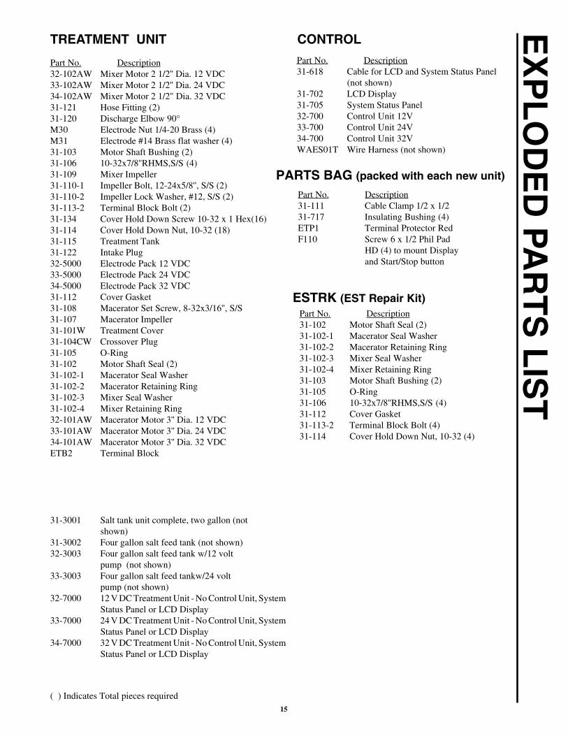
TPart No. Description32-102AW Mixer Motor 2 1/2'' Dia. 12 VDC33-102AW Mixer Motor 2 1/2'' Dia. 24 VDC34-102AW Mixer Motor 2 1/2" Dia. 32 VDC31-121 Hose Fitting (2)31-120 Discharge Elbow 90°M30 Electrode Nut 1/4-20 Brass (4)M31 Electrode #14 Brass flat washer (4)31-103 Motor Shaft Bushing (2)31-106 10-32x7/8''RHMS,S/S (4)31-109 Mixer Impeller31-110-1 Impeller Bolt, 12-24x5/8'', S/S (2)31-110-2 Impeller Lock Washer, #12, S/S (2)31-113-2 Terminal Block Bolt (2)31-134 Cover Hold Down Screw 10-32 x 1 Hex(16)31-114 Cover Hold Down Nut, 10-32 (18)31-115 Treatment Tank31-122 Intake Plug32-5000 Electrode Pack 12 VDC33-5000 Electrode Pack 24 VDC34-5000 Electrode Pack 32 VDC31-112 Cover Gasket31-108 Macerator Set Screw, 8-32x3/16'', S/S31-107 Macerator Impeller31-101W Treatment Cover31-104CW Crossover Plug31-105 O-Ring31-102 Motor Shaft Seal (2)31-102-1 Macerator Seal Washer31-102-2 Macerator Retaining Ring31-102-3 Mixer Seal Washer31-102-4 Mixer Retaining Ring32-101AW Macerator Motor 3'' Dia. 12 VDC33-101AW Macerator Motor 3'' Dia. 24 VDC34-101AW Macerator Motor 3'' Dia. 32 VDCETB2 Terminal Block
31-3001 Salt tank unit complete, two gallon (notshown)
31-3002 Four gallon salt feed tank (not shown)32-3003 Four gallon salt feed tank w/12 volt
pump (not shown)33-3003 Four gallon salt feed tankw/24 volt
pump (not shown)32-7000 12 V DC Treatment Unit - No Control Unit, System
Status Panel or LCD Display33-7000 24 V DC Treatment Unit - No Control Unit, System
Status Panel or LCD Display34-7000 32 V DC Treatment Unit - No Control Unit, System
Status Panel or LCD Display
TREATMENT UNIT
( ) Indicates Total pieces required
CONTROL
Part No. Description31-618 Cable for LCD and System Status Panel
(not shown)31-702 LCD Display31-705 System Status Panel32-700 Control Unit 12V33-700 Control Unit 24V34-700 Control Unit 32VWAES01T Wire Harness (not shown)
PARTS BAG (packed with each new unit)
Part No. Description31-111 Cable Clamp 1/2 x 1/231-717 Insulating Bushing (4)ETP1 Terminal Protector RedF110 Screw 6 x 1/2 Phil Pad
HD (4) to mount Displayand Start/Stop button
ESTRK (EST Repair Kit)Part No. Description31-102 Motor Shaft Seal (2)31-102-1 Macerator Seal Washer31-102-2 Macerator Retaining Ring31-102-3 Mixer Seal Washer31-102-4 Mixer Retaining Ring31-103 Motor Shaft Bushing (2)31-105 O-Ring31-106 10-32x7/8''RHMS,S/S (4)31-112 Cover Gasket31-113-2 Terminal Block Bolt (4)31-114 Cover Hold Down Nut, 10-32 (4)
16
OTHER INSTALLATION OPTIONS FORTHE electro-scan SYSTEM :
�()(*���+�&&�,*-
#������� $����������� %������ �������� ��� ���� ��������� �� ������ ����� ����� ���� �� ��� ����� ��� ���� ��� ��� ���������� ������������������������������������������������� �&������������ ����"�� ��������������� ����������� ��������������������������������������������������������������������������!�#������������!������������������!�������������� ��������� �"
'" ����(�)�*�+)##)*�,� $#-�%$!�%����������������������������� �������!���������������������������� �������������������!����#����������./0�������� �"!����������!�*"1"�02//3!����/'0'� +�3���)��"�4�"�5���������!�45�///'."��+�����6��������������������� �!��� ����������������������������������������� �������� ������������������������ ����"��7$#$��#*� �4� �7$� �+*$#� #$8� �#)���*� %)#9� � � *��� )� %�*9����*� :#$%$9$*�� �4� +)##)*�,%�-$#)8$"��7�����!������� ���������������������������#������������%������������#������� ��� ���� ��������������6�������������������������� �� ��������� �����"
3" �7� �+)##)*�,�9�$ �*���%�-$#����� ��� ��������������� ������!������������!���������������� �������������� ����������������������#������;����� ������������������������������������������������������� ������������������������������� �;����� ��� ������������������������� ��������� �������� ��������� ����� ������ ���������� �����&���� ��������������������������� ����������������������������� ������;����� �����������!�������������!���������� �"���������������������������� �����������������6������� �������������!������!��<�����������!��< ������� ������������) �����8��"
/" )*,�$=:#$ �+)##)*�,�*���:#�-�9$9�7$#$�*!�)*9�)*,�#$�$9,�4�#�(#$)%7��4�%�*�#)%�+7�%7�(���4�#��7� �:#�-� ��*���87��)#� $�(,���:5�%)���*��#��:$#)���*��4�5)+!�� �7$#$(,$=%5�9$9�)*9�9� %5)��$9"��)55���:5�$9�+)##)*��$ � �%7�) ��7� $��4��$#%7)*�)(�5��,�)*9�4�4��*$ �4�#�)�:)#��%�5)#�:�#:� $!� �4�)::5�%)(5$!�) �+$55�) �)*,���:5�$9�+)##)*��$ +7�%7���87��)#� $�(,���:5�%)���*��4�5)+!�)#$�$=:#$ 5,�5����$9����)��$#���4��*$�,$)#" ��$� �)�$ �9��*���)55�+�5����)���* ��*�7�+�5�*8�)�5����$9�+)##)*�,�5) � !� ���7$)(�-$�5����)���*��),�*���)::5,����,��"
>" �*9$#�*��%�#%�� �)*%$ � 7)55�#)#��)*�($�5�)(5$����:�#%7) $#��#�)*,���7$#�:$# �* �4�#)*,� :$%�)5��#�%�* $?�$*��)5�9)�)8$ !�+7$�7$#�)#� �*8������4�(#$)%7��4�+)##)*�,!(#$)%7��4�%�*�#)%�!��#���7$#+� $"�� ��$� �)�$ �9��*���)55�+��7$�$=%5� ��*��#�5����)����*��4��*%�9$*�)5��#�%�* $?�$*��)5�9)�)8$ !� ���7$�)(�-$�5����)���*��#�$=%5� ��*��),*���)::5,����,��"
." *����������������������������������@����������������<������������!���������������������������� �����������������������������������������������#���������� ���� ����������������� ����< �������� ��� ������������������������������"
A" ������������������������� ��� �������������!�������������������������������������� ��������������������������"
530 Orange Street, Millville, NJ 08332 USATelephone: 856-825-4900 FAX: 856-825-4409www.raritaneng.comSouthern Office and Plant:3101 SW Second Avenue, Fort Lauderdale, FL 33315 USATelephone: 954-525-0378 FAX: 954-764-4370
L340 0109kgs Specifications Subject to Change Without Notice Printed in U.S.A.
The electro scan has other installation options including:1) Connection to the Sealand VacuFlush®
The above option is covered by a Technical bulletinavailable from Raritan by calling: 856-825-4900 orfaxing in a request at: 856-825-4409 or on our website at:www.raritaneng.com. Request document # L286 v0107
®Vacuflush is a registered trademark of Sealand Technology, Inc.