electropneumatics basic levelelectropneumatics. subjects covered are: basic electricity, ladder...
TRANSCRIPT

Electropneumatics Basic Level
Courseware Sample 52729-F0

Order no.: 52729-10
First Edition
Revision level: 12/2016
By the staff of Festo Didactic
© Festo Didactic Ltée/Ltd, Quebec, Canada 2016
Internet: www.festo-didactic.com
e-mail: [email protected]
Printed in Canada
All rights reserved
ISBN 978-2-89747-634-2 (Printed version)
ISBN 978-2-89747-636-6 (CD-ROM)
Legal Deposit – Bibliothèque et Archives nationales du Québec, 2016
Legal Deposit – Library and Archives Canada, 2016
The purchaser shall receive a single right of use which is non-exclusive, non-time-limited and limited
geographically to use at the purchaser's site/location as follows.
The purchaser shall be entitled to use the work to train his/her staff at the purchaser’s site/location and
shall also be entitled to use parts of the copyright material as the basis for the production of his/her own
training documentation for the training of his/her staff at the purchaser’s site/location with
acknowledgement of source and to make copies for this purpose. In the case of schools/technical
colleges, training centers, and universities, the right of use shall also include use by school and college
students and trainees at the purchaser’s site/location for teaching purposes.
The right of use shall in all cases exclude the right to publish the copyright material or to make this
available for use on intranet, Internet and LMS platforms and databases such as Moodle, which allow
access by a wide variety of users, including those outside of the purchaser’s site/location.
Entitlement to other rights relating to reproductions, copies, adaptations, translations, microfilming and
transfer to and storage and processing in electronic systems, no matter whether in whole or in part, shall
require the prior consent of Festo Didactic.
Information in this document is subject to change without notice and does not represent a commitment on
the part of Festo Didactic. The Festo materials described in this document are furnished under a license
agreement or a nondisclosure agreement.
Festo Didactic recognizes product names as trademarks or registered trademarks of their respective
holders.
All other trademarks are the property of their respective owners. Other trademarks and trade names may
be used in this document to refer to either the entity claiming the marks and names or their products.
Festo Didactic disclaims any proprietary interest in trademarks and trade names other than its own.
© Festo Didactic 52729-10 III
Safety and Common Symbols
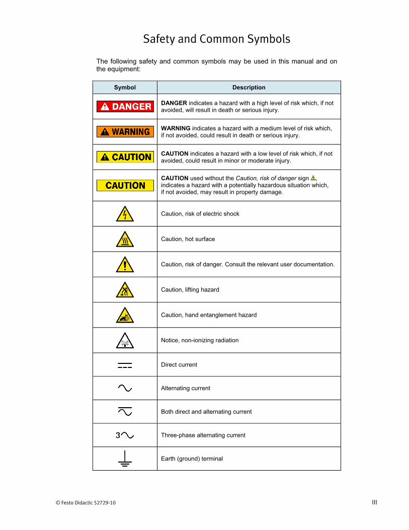
The following safety and common symbols may be used in this manual and on the equipment:
Symbol Description
DANGER indicates a hazard with a high level of risk which, if not avoided, will result in death or serious injury.
WARNING indicates a hazard with a medium level of risk which, if not avoided, could result in death or serious injury.
CAUTION indicates a hazard with a low level of risk which, if not avoided, could result in minor or moderate injury.
CAUTION used without the Caution, risk of danger sign , indicates a hazard with a potentially hazardous situation which, if not avoided, may result in property damage.
Caution, risk of electric shock
Caution, hot surface
Caution, risk of danger. Consult the relevant user documentation.
Caution, lifting hazard
Caution, hand entanglement hazard
Notice, non-ionizing radiation
Direct current
Alternating current
Both direct and alternating current
Three-phase alternating current
Earth (ground) terminal

Safety and Common Symbols
IV © Festo Didactic 52729-10
Symbol Description
Protective conductor terminal
Frame or chassis terminal
Equipotentiality
On (supply)
Off (supply)
Equipment protected throughout by double insulation or reinforced insulation
In position of a bi-stable push control
Out position of a bi-stable push control
© Festo Didactic 52729-10 V
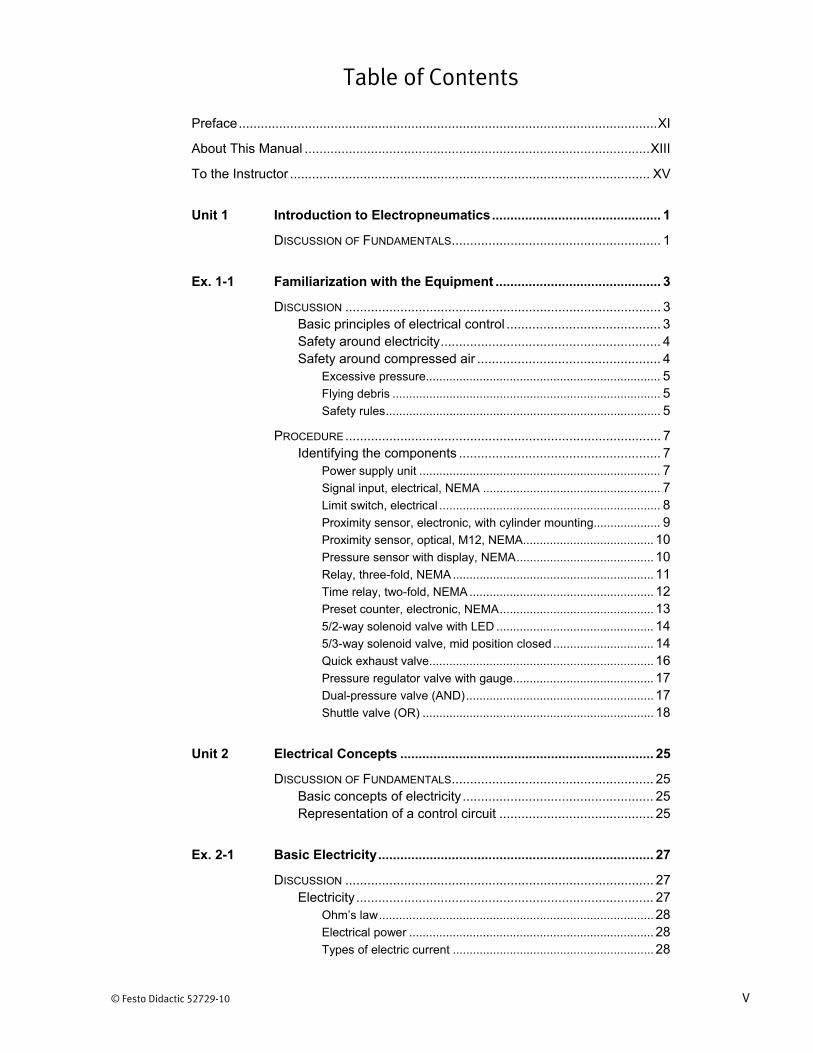
Table of Contents
Preface .................................................................................................................. XI
About This Manual .............................................................................................. XIII
To the Instructor .................................................................................................. XV
Unit 1 Introduction to Electropneumatics .............................................. 1
DISCUSSION OF FUNDAMENTALS ......................................................... 1
Ex. 1-1 Familiarization with the Equipment ............................................. 3
DISCUSSION ...................................................................................... 3 Basic principles of electrical control .......................................... 3 Safety around electricity ............................................................ 4 Safety around compressed air .................................................. 4
Excessive pressure...................................................................... 5 Flying debris ................................................................................ 5 Safety rules .................................................................................. 5
PROCEDURE ...................................................................................... 7 Identifying the components ....................................................... 7
Power supply unit ........................................................................ 7 Signal input, electrical, NEMA ..................................................... 7 Limit switch, electrical .................................................................. 8 Proximity sensor, electronic, with cylinder mounting.................... 9 Proximity sensor, optical, M12, NEMA ....................................... 10 Pressure sensor with display, NEMA ......................................... 10 Relay, three-fold, NEMA ............................................................ 11 Time relay, two-fold, NEMA ....................................................... 12 Preset counter, electronic, NEMA .............................................. 13 5/2-way solenoid valve with LED ............................................... 14 5/3-way solenoid valve, mid position closed .............................. 14 Quick exhaust valve ................................................................... 16 Pressure regulator valve with gauge .......................................... 17 Dual-pressure valve (AND) ........................................................ 17 Shuttle valve (OR) ..................................................................... 18
Unit 2 Electrical Concepts ..................................................................... 25
DISCUSSION OF FUNDAMENTALS ....................................................... 25 Basic concepts of electricity .................................................... 25 Representation of a control circuit .......................................... 25
Ex. 2-1 Basic Electricity ........................................................................... 27
DISCUSSION .................................................................................... 27 Electricity ................................................................................. 27
Ohm’s law .................................................................................. 28 Electrical power ......................................................................... 28 Types of electric current ............................................................ 28
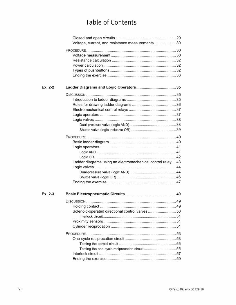
Table of Contents
VI © Festo Didactic 52729-10
Closed and open circuits ......................................................... 29 Voltage, current, and resistance measurements .................... 30
PROCEDURE .................................................................................... 30 Voltage measurement ............................................................. 30 Resistance calculation ............................................................ 32 Power calculation .................................................................... 32 Types of pushbuttons .............................................................. 32 Ending the exercise ................................................................. 33
Ex. 2-2 Ladder Diagrams and Logic Operators ..................................... 35
DISCUSSION .................................................................................... 35 Introduction to ladder diagrams .............................................. 35 Rules for drawing ladder diagrams ......................................... 36 Electromechanical control relays ............................................ 37 Logic operators ....................................................................... 37 Logic valves ............................................................................ 38
Dual-pressure valve (logic AND) ................................................ 38 Shuttle valve (logic inclusive OR) ............................................... 39
PROCEDURE .................................................................................... 40 Basic ladder diagram .............................................................. 40 Logic operators ....................................................................... 41
Logic AND .................................................................................. 41 Logic OR .................................................................................... 42
Ladder diagrams using an electromechanical control relay .... 43 Logic valves ............................................................................ 44
Dual-pressure valve (logic AND) ................................................ 44 Shuttle valve (logic OR) ............................................................. 46
Ending the exercise ................................................................. 47
Ex. 2-3 Basic Electropneumatic Circuits ............................................... 49
DISCUSSION .................................................................................... 49 Holding contact ....................................................................... 49 Solenoid-operated directional control valves .......................... 50
Interlock circuit ........................................................................... 51 Proximity sensors .................................................................... 51 Cylinder reciprocation ............................................................. 51
PROCEDURE .................................................................................... 53 One-cycle reciprocation circuit ................................................ 53
Testing the control circuit ........................................................... 55 Testing the one-cycle reciprocation circuit ................................. 55
Interlock circuit ........................................................................ 57 Ending the exercise ................................................................. 59

Table of Contents
© Festo Didactic 52729-10 VII
Unit 3 Sequence Systems ...................................................................... 65
DISCUSSION OF FUNDAMENTALS ....................................................... 65
Ex. 3-1 Basic Memory and Priority ......................................................... 67
DISCUSSION .................................................................................... 67 Memory circuit ......................................................................... 67 Limit switches .......................................................................... 68
Limit switches symbols .............................................................. 70
PROCEDURE .................................................................................... 71 Basic memory and priority circuit ............................................ 71 Priority locking circuit .............................................................. 72 Priority locking circuit using limit switches .............................. 75
Mounting of the limit-switch assembly ....................................... 75 Connecting the priority locking circuit ........................................ 76
Ending the exercise ................................................................. 78
Ex. 3-2 Multi-Pressure Systems .............................................................. 81
DISCUSSION .................................................................................... 81 Multi-pressure system ............................................................. 81 Pressure sensors .................................................................... 82
Hysteresis .................................................................................. 82 Features of the training system pressure sensor ....................... 83
PROCEDURE .................................................................................... 84 Operation of a pressure sensor .............................................. 84 Multi-pressure system – selecting between two pressures .... 87 Multi-pressure system – double-acting cylinder ...................... 91 Ending the exercise ................................................................. 94
Ex. 3-3 Sequencing Pneumatic Circuits ................................................. 97
DISCUSSION .................................................................................... 97 Pneumatic sequencing of cylinders ........................................ 97
Simple sequencing circuit .......................................................... 98 Adding security to a sequencing circuit ...................................... 99
Cascade circuits .................................................................... 101
PROCEDURE .................................................................................. 103 Sequencing circuit ................................................................. 103 Ending the exercise ............................................................... 107
Ex. 3-4 Time-Delay Electropneumatic Applications ........................... 109
DISCUSSION .................................................................................. 109 Time delays ........................................................................... 109 Time-delay relays .................................................................. 109
On-delay and off-delay symbols .............................................. 110

Table of Contents
VIII © Festo Didactic 52729-10
Time-delay valves ................................................................. 111
PROCEDURE .................................................................................. 114 Operation of a time-delay relay ............................................. 114 Operation of a time-delay valve ............................................ 117 Dwell period control using a time-delay relay ....................... 119 Ending the exercise ............................................................... 122
Unit 4 Industrial Applications .............................................................. 129
DISCUSSION OF FUNDAMENTALS ..................................................... 129
Ex. 4-1 Deceleration of Actuators ......................................................... 131
DISCUSSION .................................................................................. 131 Deceleration of a pneumatic cylinder .................................... 131
Cushioned cylinders ................................................................. 131 External cushioning using electrical control ............................. 132
Stopping of a pneumatic motor ............................................. 133 Unidirectional motor ................................................................. 134 Bidirectional motor ................................................................... 135
PROCEDURE .................................................................................. 136 Deceleration of a pneumatic cylinder .................................... 136 Stopping of a unidirectional pneumatic motor ....................... 139
Vacuum generation at inlet port ............................................... 139 Effect of the valve configuration ............................................... 141
Ending the exercise ............................................................... 144
Ex. 4-2 Counting of Actuator Cycles .................................................... 147
DISCUSSION .................................................................................. 147 Electrical counters ................................................................. 147 Basic counter operation ........................................................ 147 Continuous reciprocation of a cylinder .................................. 148 Optical proximity sensor ........................................................ 150 Features of the training system ............................................. 151
Preset counter unit ................................................................... 151 Optical proximity sensor ........................................................... 151
PROCEDURE .................................................................................. 152 Operation of the preset counter unit ..................................... 152 Continuous reciprocation of a cylinder .................................. 153 Operation of an optical proximity sensor ............................... 157 Counting of motor revolutions ............................................... 157 Ending the exercise ............................................................... 160

Table of Contents
© Festo Didactic 52729-10 IX
Ex. 4-3 Industrial Drilling System and Safety Circuits ....................... 163
DISCUSSION .................................................................................. 163 Industrial drilling systems ...................................................... 163 Quick exhaust valve .............................................................. 166 Safety circuits ........................................................................ 167 Two-hand safety circuits ....................................................... 167
PROCEDURE .................................................................................. 170 Simulated drilling system ...................................................... 170 Basic two-hand safety circuit ................................................ 173 Two-hand, non-tie-down safety circuit .................................. 176 Ending the exercise ............................................................... 177
Ex. 4-4 Garbage Compactor Circuit ...................................................... 179
DISCUSSION .................................................................................. 179 Garbage compactor circuit .................................................... 179
PROCEDURE .................................................................................. 181 Design of an electrical control circuit .................................... 181 Testing the circuit .................................................................. 184 Ending the exercise ............................................................... 186
Unit 5 Troubleshooting ........................................................................ 193
DISCUSSION OF FUNDAMENTALS ..................................................... 193
Ex. 5-1 Troubleshooting Electrical Control Circuits ........................... 195
DISCUSSION .................................................................................. 195 Voltmeter method of troubleshooting .................................... 195 Ohmmeter method of troubleshooting (continuity test method) ................................................................................. 197
PROCEDURE .................................................................................. 199 Setting up the industrial drilling system ................................. 199 Troubleshooting of an electrical control circuit ...................... 202
Guided troubleshooting of a fault ............................................. 202 Troubleshooting an unknown fault ........................................... 204
Ending the exercise ............................................................... 207
Ex. 5-2 Troubleshooting Electropneumatic Systems ......................... 209
DISCUSSION .................................................................................. 209 Troubleshooting methods ..................................................... 209

Table of Contents
X © Festo Didactic 52729-10
PROCEDURE .................................................................................. 210 Setting up the industrial drilling system (modified) ............... 210 Troubleshooting an electropneumatic system ...................... 214
Guided troubleshooting of a fault ............................................. 214 Troubleshooting an unknown fault ........................................... 215
Ending the exercise ............................................................... 217
Appendix A Equipment Utilization Chart ..................................................... 223
Appendix B Status Verification Procedure of the Training System .......... 225
Appendix C Glossary of New Terms ............................................................. 227
Appendix D Equipment Symbols .................................................................. 231
Appendix E Pneumatic Generic Symbols .................................................... 237
Appendix F Electropneumatic Generic Symbols ........................................ 245
Appendix G Conversion Factors ................................................................... 249
Index................................................................................................................... 251

© Festo Didactic 52729-10 XI
Preface
This training system is a modularized presentation of the principles of pneumatics and its controlled application. Successful completion of the exercises in this training program will provide the student with considerable literacy on the basics of pneumatics, as well as hands-on experience with practical circuits.
The training program is based on two manuals: Pneumatics Basic Level covers the basic principles of pneumatics, while Electropneumatics Basic Level covers electrical circuits and ladder diagrams for pneumatics applications.
Use for intended purpose
The training system from Festo Didactic has been developed and produced exclusively for training and further education in the field of automation and technology. The respective training companies and/or trainers must ensure that all trainees observe the safety precautions which are described in this manual.
Festo Didactic hereby excludes any and all liability for damages suffered by trainees, the training company and/or any third parties, which occur during use of the equipment in situations which serve any purpose other than training and/or further education, unless such damages have been caused by Festo Didactic due to malicious intent or gross negligence.
We invite readers of this manual to send us their tips, feedback, and suggestions for improving the book.
Please send these to [email protected].
The authors and Festo Didactic look forward to your comments.

© Festo Didactic 52729-10 XIII
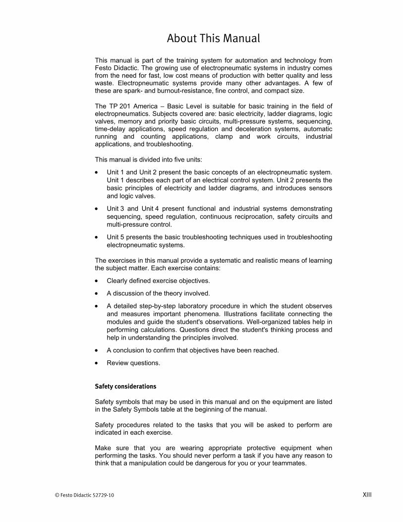
About This Manual
This manual is part of the training system for automation and technology from Festo Didactic. The growing use of electropneumatic systems in industry comes from the need for fast, low cost means of production with better quality and less waste. Electropneumatic systems provide many other advantages. A few of these are spark- and burnout-resistance, fine control, and compact size.
The TP 201 America – Basic Level is suitable for basic training in the field of electropneumatics. Subjects covered are: basic electricity, ladder diagrams, logic valves, memory and priority basic circuits, multi-pressure systems, sequencing, time-delay applications, speed regulation and deceleration systems, automatic running and counting applications, clamp and work circuits, industrial applications, and troubleshooting.
This manual is divided into five units:
Unit 1 and Unit 2 present the basic concepts of an electropneumatic system. Unit 1 describes each part of an electrical control system. Unit 2 presents the basic principles of electricity and ladder diagrams, and introduces sensors and logic valves.
Unit 3 and Unit 4 present functional and industrial systems demonstrating sequencing, speed regulation, continuous reciprocation, safety circuits and multi-pressure control.
Unit 5 presents the basic troubleshooting techniques used in troubleshooting electropneumatic systems.
The exercises in this manual provide a systematic and realistic means of learning the subject matter. Each exercise contains:
Clearly defined exercise objectives.
A discussion of the theory involved.
A detailed step-by-step laboratory procedure in which the student observes and measures important phenomena. Illustrations facilitate connecting the modules and guide the student's observations. Well-organized tables help in performing calculations. Questions direct the student's thinking process and help in understanding the principles involved.
A conclusion to confirm that objectives have been reached.
Review questions.
Safety considerations
Safety symbols that may be used in this manual and on the equipment are listed in the Safety Symbols table at the beginning of the manual.
Safety procedures related to the tasks that you will be asked to perform are indicated in each exercise.
Make sure that you are wearing appropriate protective equipment when performing the tasks. You should never perform a task if you have any reason to think that a manipulation could be dangerous for you or your teammates.
About This Manual
XIV © Festo Didactic 52729-10
Each circuit should be checked carefully for proper hook-up. Every student should be cautioned NEVER to activate the sytem before the circuit has been checked. The spaces for checking off each step should be used regardless of how simple the exercise might appear.
Every student should know the safety rules shown in Exercise 1-1 of this manual before performing the exercises.
Systems of units
Units are expressed using the International System of Units (SI) followed by units expressed in the U.S. customary system of units (between parentheses).

© Festo Didactic 52729-10 XV
To the Instructor
You will find in this Instructor Guide all the elements included in the Student Manual together with the answers to all questions, results of measurements, graphs, explanations, suggestions, and, in some cases, instructions to help you guide the students through their learning process. All the information that applies to you is placed between markers and appears in red.
Accuracy of measurements
The numerical results of the hands-on exercises may differ from one student to another. For this reason, the results and answers given in this manual should be considered as a guide. Students who correctly performed the exercises should expect to demonstrate the principles involved and make observations and measurements similar to those given as answers.
The instructor should be familiar with the subject matter in order to recognize erroneous results. It is advised to include a complete run-through of each exercise in the instructor’s preparation for class.
Compressed air supply
As a compressed air source, use a compressed air distribution system or an air compressor. The compressed air supply must deliver a pressure of at least 6 bar (85 psi) and a flowrate of at least 100 l/min (3.5 SCFM).
Working pressure should not exceed 6 bar (85 psi).


Sample Exercise
Extracted from
the Student Manual
and the Instructor Guide


© Festo Didactic 52729-10 49
To learn about holding contacts and interlock circuits;
To become familiar with indirect control using solenoid-operated directional control valves.
To describe the function and operation of magnetic proximity switches;
To learn about cylinder reciprocation.
The Discussion of this exercise covers the following points:
Holding contact Solenoid-operated directional control valves
Interlock circuit. Proximity sensors Cylinder reciprocation
Holding contact
Holding contacts are basic elements of ladder diagrams. They keep a relay coil energized after the system starts.
Figure 2-16 shows a basic circuit without a holding contact. In this circuit, pushing PB1 energizes relay coil CR1. With CR1 energized, contact CR1-1 closes and indicator light L1 turns on. Yet, releasing PB1 turns L1 off immediately.
Figure 2-16. Basic circuit without holding contact.
Figure 2-17 shows the circuit with the added holding contact CR1-2. When the user pushes and then releases PB1, L1 stays on. Indeed, current continues to flow to relay coil CR1 through the alternate path the holding contact CR1-2 provides. Current stops flowing in the rung when the user pushes PB2.
Basic Electropneumatic Circuits
Exercise 2-3
EXERCISE OBJECTIVE
DISCUSSION OUTLINE
DISCUSSION

Ex. 2-3 – Basic Electropneumatic Circuits Discussion
50 © Festo Didactic 52729-10
Figure 2-17. Basic circuit with holding contact.
Solenoid-operated directional control valves
Solenoid-operated directional control valves have distinct advantages over pilot-operated and manually-operated directional control valves. Solenoid-operated valves react almost instantly to the electrical switching signal, while the response time of pilot-operated valves depends on pilot pressure, tubing size, and tubing length.
In a solenoid-operated valve, the electric current flowing through the solenoid coil produces a magnetic field that moves a plunger. Moving the plunger opens a small pneumatic valve that allows pilot pressure to push the spool into its operated position. Note that the spool of the valve will not move if compressed air is not supplied to the valve, even though an electric current flows through the solenoid.
Figure 2-18 shows a 5-port, 3-position, solenoid valve and its symbol. On such a valve, each solenoid usually has a LED to indicate its activation status. A manual override also allows to operate the spool without energizing the solenoid.
a The valve below has its mid position closed. Not all 5/3 valves have this configuration.
Figure 2-18. Solenoid-operated directional control valve and symbol.
Symbol LED
Manualoverride
Solenoid
SolenoidAir pilot
Manualoverride
Ex. 2-3 – Basic Electropneumatic Circuits Discussion
© Festo Didactic 52729-10 51
Interlock circuit
When using a double solenoid-operated valve, it is important to use an interlock circuit to prevent both solenoids from being energized at the same time. You will construct and operate an interlock circuit in the procedure of the exercise.
Proximity sensors
Proximity sensors operate without contact and without an external mechanical actuating force. As a result, they have a long service life and high switching reliability. The various types of proximity sensors are:
Reed switches
Inductive proximity sensors
Capacitive proximity sensors
Optical proximity sensors
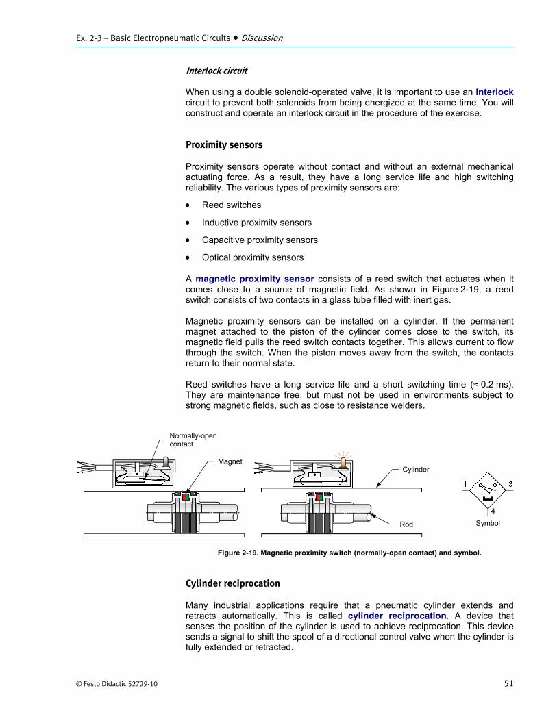
A magnetic proximity sensor consists of a reed switch that actuates when it comes close to a source of magnetic field. As shown in Figure 2-19, a reed switch consists of two contacts in a glass tube filled with inert gas.
Magnetic proximity sensors can be installed on a cylinder. If the permanent magnet attached to the piston of the cylinder comes close to the switch, its magnetic field pulls the reed switch contacts together. This allows current to flow through the switch. When the piston moves away from the switch, the contacts return to their normal state.
Reed switches have a long service life and a short switching time (≈ 0.2 ms). They are maintenance free, but must not be used in environments subject to strong magnetic fields, such as close to resistance welders.
Figure 2-19. Magnetic proximity switch (normally-open contact) and symbol.
Cylinder reciprocation
Many industrial applications require that a pneumatic cylinder extends and retracts automatically. This is called cylinder reciprocation. A device that senses the position of the cylinder is used to achieve reciprocation. This device sends a signal to shift the spool of a directional control valve when the cylinder is fully extended or retracted.
Symbol
MagnetCylinder
Rod
Normally-open contact

Ex. 2-3 – Basic Electropneumatic Circuits Discussion
52 © Festo Didactic 52729-10
Figure 2-20 and Figure 2-21 show the pneumatic diagram and the ladder diagram of an electropneumatic application with a cylinder having a one-cycle reciprocation. One-cycle reciprocation means that the cylinder rod extends, retracts, and stops without intervention from the operator. A solenoid-operated directional control valve activated by a magnetic proximity switch is frequently used to achieve automatic retraction of the cylinder.
Figure 2-20. Pneumatic diagram of a one-cycle reciprocation circuit.
Figure 2-21. Ladder diagram of a one-cycle reciprocation circuit.

Ex. 2-3 – Basic Electropneumatic Circuits Procedure Outline
© Festo Didactic 52729-10 53
a On this ladder diagram, the arrow beside magnetic proximity switch PX1 indicates that the switch is activated in the idle position.
As shown on the diagrams, the magnetic proximity switch PX1 confirms that the rod of the cylinder is retracted and PX2 confirms that the rod is extended.
Before the operator pushes PB1, the cylinder rod is retracted. Relay coil CR1 is activated because PX1 detects the position of the cylinder rod. When the operator pushes PB1, current flows in rung 3 via CR1-1 and CR2-1. This energizes CR3, which closes CR3-1 and CR3-2.
When CR3-2 closes, current flows in rung 4 and energizes the solenoid DCV1-SOLA. This shifts the flow path in the directional control valve, which allows pressurized air to reach the piston.
When the operator releases PB1, current continues to flow to relay coil CR3 through the alternate path that the holding contact CR3-1 provides. This keeps CR3 energized and, therefore, DCV1-SOLA stays energized. Without the holding contact CR3-1, the cylinder rod would retract immediately when the operator releases PB1.
When the cylinder is fully extended, it activates PX2. This energizes CR2, which opens the normally-closed contact CR2-1. Opening CR2-1 de-energizes rung 3 and rung 4. The spool of the directional control valve shifts back to its normal position and the cylinder rod retracts. Once the piston is back to its original position, the system is ready for another cycle.
The Procedure is divided into the following sections:
One-cycle reciprocation circuit Testing the control circuit. Testing the one-cycle reciprocation circuit.
Interlock circuit Ending the exercise
One-cycle reciprocation circuit
1. Verify the status of the training system according to the procedure given in Appendix B.
2. Look at the pneumatic diagram in Figure 2-22. Do not perform the connections yet; simply place the components on your work surface and install the proximity switches on the double-acting cylinder.
Screw a tip to the cylinder rod.
Connect the components according to the ladder diagram in Figure 2-23.
PROCEDURE OUTLINE
PROCEDURE
Ex. 2-3 – Basic Electropneumatic Circuits Procedure
54 © Festo Didactic 52729-10
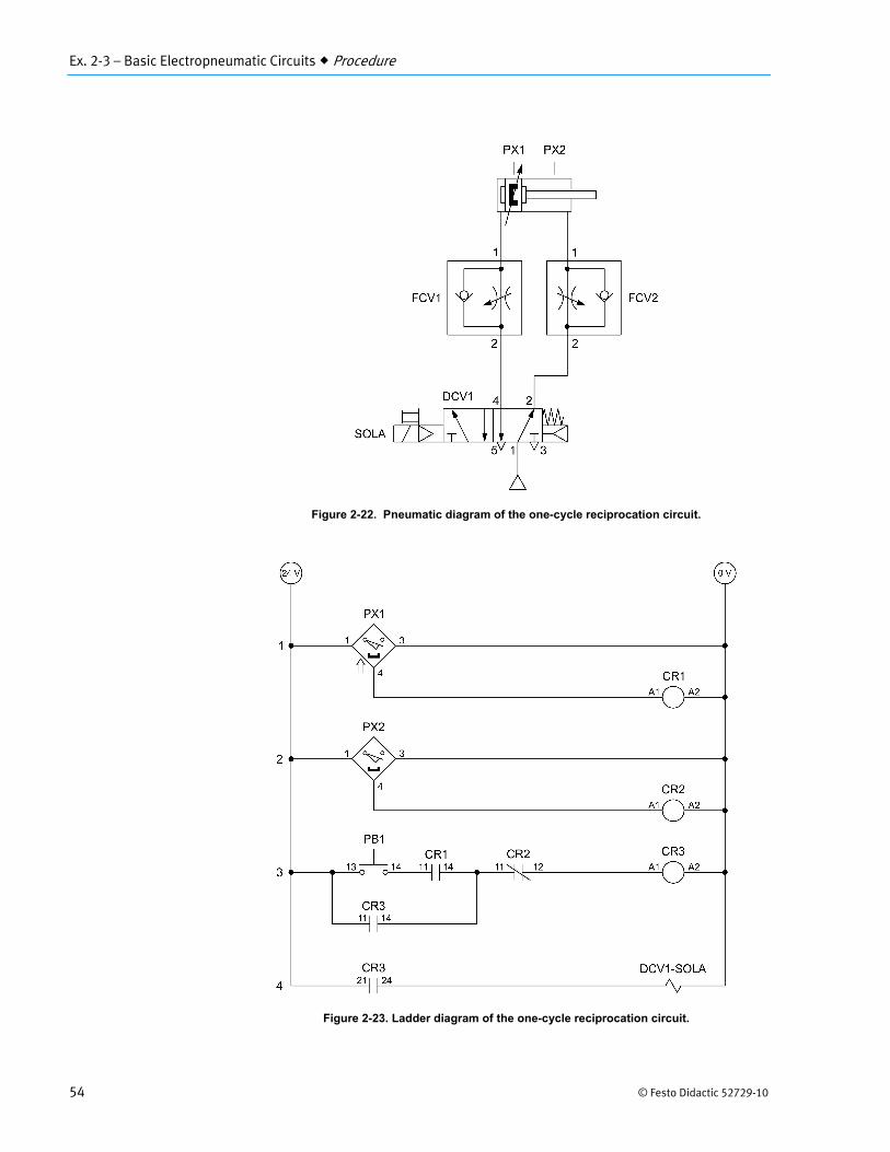
Figure 2-22. Pneumatic diagram of the one-cycle reciprocation circuit.
Figure 2-23. Ladder diagram of the one-cycle reciprocation circuit.
Ex. 2-3 – Basic Electropneumatic Circuits Procedure
© Festo Didactic 52729-10 55
Testing the control circuit
3. Make sure that your electrical circuit and the magnetic proximity sensors are operational. To do so, turn on the power supply, and make sure that CR1 activates if the rod is fully retracted. Also, verify that CR2 activates if the rod is fully extended.
4. Retract the cylinder rod. Push PB1 and verify that the LED of DCV1-SOLA turns on to indicate that the solenoid is energized.
5. Fully extend the cylinder rod. If your circuit is operational, the LED of DCV1-SOLA should turn off. Explain why.
When the cylinder rod is fully extended, the permanent magnet in the cylinder activates PX2. This energizes CR2, which opens CR2-1. Current stops flowing in rung 3, which de-energizes CR3. This, in turn, de-energizes rung 4 and DCV1-SOLA.
6. Retract the cylinder rod and connect the components according to the pneumatic diagram in Figure 2-22.
Testing the one-cycle reciprocation circuit
7. Fully close both flow control valves, and then open each of them by turning their knob about ten turns.
The flow control valves are used in a meter-out configuration to control the extension and retraction speed of the cylinder. Adjust the valves openings if required.
8. On the start-up valve:
Set the pressure at 4 bar (60 psi) on the regulated pressure gauge.
Open the on/off valve.
9. Push PB1. Describe the operation of the cylinder rod.
Pushing PB1 extends the rod. The rod continues to extend to full stroke even if PB1 is released. Once it is fully extended, the cylinder rod retracts and stops.
10. By referring to the ladder diagram in Figure 2-23, explain why the cylinder rod continues to extend if you release PB1.
The current continues to flow to CR3 through holding contact CR3-1. Hence, DCV1-SOLA on rung 4 stays energized through CR3-2.

Ex. 2-3 – Basic Electropneumatic Circuits Procedure
56 © Festo Didactic 52729-10
11. Does the cylinder rod perform more than one cycle?
No. The cylinder rod stops after one cycle.
12. By referring to the ladder diagram in Figure 2-23, explain why the cylinder rod automatically retracts when the rod is fully extended.
When the cylinder rod is fully extended, the permanent magnet in the cylinder activates PX2. This energizes CR2, which opens CR2-1. Current stops flowing in rung 3, which de-energizes CR3. This, in turn, de-energizes rung 4 and DCV1-SOLA. The spring of the directional control valve shifts the spool, which retracts the cylinder rod.
13. Loosen the setscrew on PX2 until the clamp is loose enough to slip over the cylinder. Position the sensor approximately at the middle of the cylinder, and then tighten the setscrew.
Push PB1 and observe the extension of the cylinder rod. What can you conclude about the influence of the position of PX2 on the behavior of the system?
The position of the magnetic proximity sensor determines where the cylinder rod stops when extending.
14. What will happen to the system operation if relay contact CR3-1 is removed from the circuit? Explain.
The cylinder rod will retract as soon as PB1 is released.
15. Return the magnetic proximity sensor to its original position and turn off the power supply.
Using a small screwdriver, carefully turn the manual override screw of DCV1-SOLA clockwise. Describe and explain what happens.
The cylinder rod extends. The manual override can be used to operate the spool of the directional control valve without electrical power.
16. Return the manual override screw of DCV1-SOLA to its original position.
17. Close the on/off valve, turn off the power supply, and disconnect your circuit.
Ex. 2-3 – Basic Electropneumatic Circuits Procedure
© Festo Didactic 52729-10 57
Interlock circuit
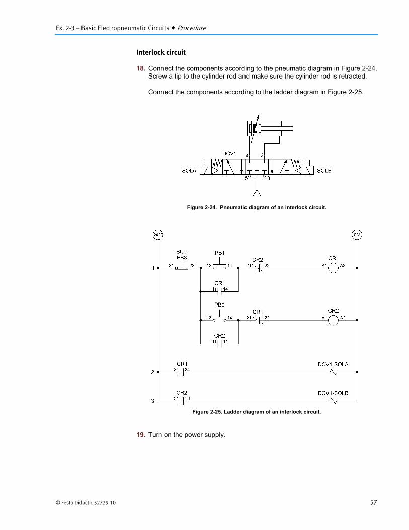
18. Connect the components according to the pneumatic diagram in Figure 2-24. Screw a tip to the cylinder rod and make sure the cylinder rod is retracted.
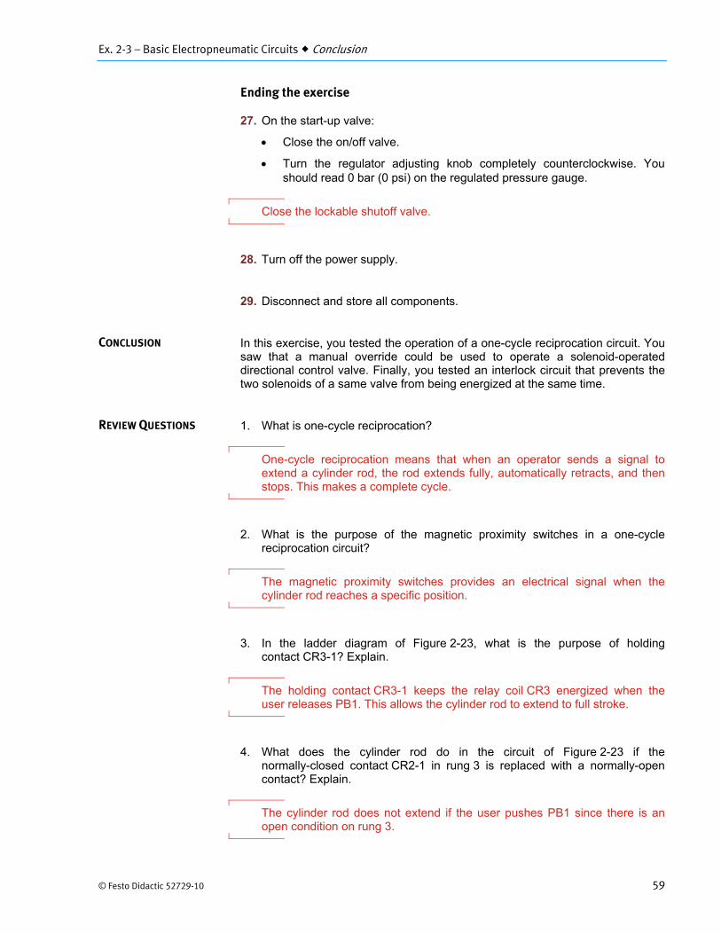
Connect the components according to the ladder diagram in Figure 2-25.
Figure 2-24. Pneumatic diagram of an interlock circuit.
Figure 2-25. Ladder diagram of an interlock circuit.
19. Turn on the power supply.

Ex. 2-3 – Basic Electropneumatic Circuits Procedure
58 © Festo Didactic 52729-10
20. On the start-up valve:
Set the pressure at 2 bar (30 psi) on the regulated pressure gauge.
Open the on/off valve.
21. Push PB1. The LED of DCV1-SOLA should turn on and the cylinder rod should extend.
Does the LED of DCV1-SOLA stay on when you release PB1? Explain why.
Yes. Current continues to flow to relay coil CR1 through the holding contact CR1-1.
22. Push PB2. Does the LED of DCV1-SOLB turn on? Explain why.
No. The LED of DCV1-SOLB does not turn on because the holding contact CR1-1 maintains CR1 energized, which keeps CR1-2 open.
23. What should you do to energize DCV1-SOLB? Explain.
Pushing PB3 opens rung 1. This de-energizes CR1, opens the holding contact CR1-1, and closes CR1-2. In these conditions, one can then push PB2 to energize CR2, which energizes DCV1-SOLB.
24. Push PB3 and then push PB2. Does the LED of solenoid DCV1-SOLB turn on?
Yes No
Yes
25. Push PB3 and then push PB1 and PB2 at the same time. Do the LEDs of solenoids DCV1-SOLA and DCV1-SOLB turn on?
Yes No
No
26. What does the interlock circuit prevents?
It prevents both solenoids from being energized at the same time.
Ex. 2-3 – Basic Electropneumatic Circuits Conclusion
© Festo Didactic 52729-10 59
Ending the exercise
27. On the start-up valve:
Close the on/off valve.
Turn the regulator adjusting knob completely counterclockwise. You should read 0 bar (0 psi) on the regulated pressure gauge.
Close the lockable shutoff valve.
28. Turn off the power supply.
29. Disconnect and store all components.
In this exercise, you tested the operation of a one-cycle reciprocation circuit. You saw that a manual override could be used to operate a solenoid-operated directional control valve. Finally, you tested an interlock circuit that prevents the two solenoids of a same valve from being energized at the same time.
1. What is one-cycle reciprocation?
One-cycle reciprocation means that when an operator sends a signal to extend a cylinder rod, the rod extends fully, automatically retracts, and then stops. This makes a complete cycle.
2. What is the purpose of the magnetic proximity switches in a one-cycle reciprocation circuit?
The magnetic proximity switches provides an electrical signal when the cylinder rod reaches a specific position.
3. In the ladder diagram of Figure 2-23, what is the purpose of holding contact CR3-1? Explain.
The holding contact CR3-1 keeps the relay coil CR3 energized when the user releases PB1. This allows the cylinder rod to extend to full stroke.
4. What does the cylinder rod do in the circuit of Figure 2-23 if the normally-closed contact CR2-1 in rung 3 is replaced with a normally-open contact? Explain.
The cylinder rod does not extend if the user pushes PB1 since there is an open condition on rung 3.
CONCLUSION
REVIEW QUESTIONS

Ex. 2-3 – Basic Electropneumatic Circuits Review Questions
60 © Festo Didactic 52729-10
5. What does the cylinder rod do in the circuit of Figure 2-23 if the normally-open contact CR3-2 in rung 4 is replaced with a normally-closed contact? Explain.
The cylinder rod extends immediately after power up since a complete conducting path exists on rung 4. Once the cylinder rod is fully extended, solenoid DCV1-SOLA stays energized.

Unit 2 – Electrical Concepts Unit Test
© Festo Didactic 52729-10 61
Unit Test
1. According to Ohm’s law,
a. voltage drop is equal to current multiplied by resistance. b. current is equal to voltage drop divided by resistance. c. resistance is equal to voltage drop divided by current. d. All of the above.
d
2. If a 2 A current flows in a resistor and this resistor produces a voltage drop of 10 V. What is the power dissipated by the resistor?
a. 40 W b. 200 W c. 20 W d. 5 W
c
3. Which of the following is false?
a. To measure the voltage drop across a component, you must connect a multimeter in parallel.
b. To measure the current in a component, you must connect a multimeter in parallel with the component.
c. To measure the resistance value of a component, you must disconnect the component from the circuit.
d. To measure the current in a component, you must connect a multimeter in series with the component.
b
4. If the voltage across a resistor is 12 V and the current flowing through it is 2 A. What is the resistance value of this resistor?
a. 24 Ω b. 6 Ω c. 48 Ω d. 4 Ω
b

Unit 2 – Electrical Concepts Unit Test
62 © Festo Didactic 52729-10
5. A shuttle valve outputs
a. the lower of two input pressures. b. the higher of two input pressures. c. the first pressure applied of two input pressures. d. the last pressure applied of two input pressures.
b
6. What happens when the coil of an electromechanical control relay is energized?
a. Normally-open contacts open, while normally-closed contacts close. b. The relay contacts return to their normal state. c. The coil burns out. d. Normally-open contacts close, while normally-closed contacts open.
d
7. In a ladder rung containing two normally-closed contacts in series, what is the condition required for the output load to energize?
a. Both contacts must be deactivated. b. One of the contacts must be activated. c. One of the contacts must be deactivated. d. Both contacts must be activated.
a
8. To actuate a reed switch, a cylinder must have a
a. piece of iron attached to its piston. b. capacitor attached to its piston. c. resistor attached to its piston. d. permanent magnet attached to its piston.
d
9. One-cycle reciprocation means that when an operator start the circuit, the cylinder rod
a. extends fully and then stops. b. extends and retracts two times. c. extends and retracts once. d. extends and retracts indefinitely.
c
Unit 2 – Electrical Concepts Unit Test
© Festo Didactic 52729-10 63
10. To which of the following logic operators is a shuttle valve analog?
a. AND b. XOR c. OR d. NOT
c
Index
252 © Festo Didactic 52729-10
rapid-traverse, slow-feed method ...................................................................... 130 resistance ............................................................................. 25, 27, 28, 30, 51, 195 safety circuit ....................................................................................... 161, 165, 166 sequence .............................................................................................................. 65 sequence systems ............................................................................................... 65 series ........................................................................ 2, 30, 35, 36, 37, 83, 109, 165 shuttle valve ............................................................................................. 35, 38, 39 solenoid-operated directional control valves .................................................... 4, 50 spool .................................................... 50, 51, 53, 67, 68, 101, 102, 103, 111, 164 time-delay relay .................................................................. 109, 110, 114, 166, 178 time-delay valve ......................................................................................... 109, 111 troubleshooting ................................................................................... 191, 207, 208 two-hand safety circuit ............................................................................... 161, 165 vacuum generation ..................................................................................... 132, 133 voltage ................................................................ 25, 27, 28, 30, 149, 166, 193, 194 voltage tracing .................................................................................................... 193 voltmeter method ............................................................................... 191, 193, 196

This page should be left blank