electronic/electric technology benefits study · electronic/electric technology benefits study w....
TRANSCRIPT

, \ "
"
','\
I' \
I "
\ ! I
I
NASA Contractor Report 165890
~51t (!,fJ Ib~T<JtJ
NASA-CR-165890 19820020367
Electronic/Electric Technology Benefits Study
w.w. Howison, MJ. Cronin
LOCKHEED-CALIFORNIA COMPANY BURBANK, CALIFORNIA
CONTRACT NASl-16199 May 1982
NI\SI\ National Aeronautics and Space Administration
Langley Research Center Hampton. Virginia 23665
I:'~():~l I.·~EI1EIC:r\TC;E
,.. .... '" .,., .... ·./":""=' .. ,,;:,~ .. n;~:.'·~~
.,tiot f.O,nE 'IAtXU fllOH tu::s nCQ~,t
~ fl\Hlfl.nH r~py GtU61hl\1 ,~J_ •
. } ij l 1?, 1982
}.ANGLEY R;:Sf':AR;~~' ,;t:rHER LlGR.<l,RY. NASA
HM,lPTON, VIRGINIA
i 111111111111111111111111111111111111111111111 NF01942
https://ntrs.nasa.gov/search.jsp?R=19820020367 2020-04-03T23:05:31+00:00Z

.- '
~ j 8 j
: g j i to I i ~ I : ~ j
j j j j j j j j j j j
j j j j j j
j j j
j j
j
j

"'
1
,'"")
I)
,~
/ t
I NASA Contractor Report 165890
Electronic/Electric Technology Benefits Study
w.w. Howison, MJ. Cronin
LOCKHEED-CALIFORNIA COMPANY BURBANK, CALIFORNIA
CONTRACT NASI-16199 May 1982
NI\SI\ National Aeronautics and Space Administration
Langley Research Center Hampton, Virginia 23665
.p.: ;1Ill;-01 y~ 7"3

-,

"'\
',1
,,.,
,,'
~
,-
'·l
TABLE OF CONTENTS
1- INTRODUCTION
2. SUMMARY . . . . . . ABBREVIATIONS AND ACRONYMS · · · · .
3. APPROACH . . . . . . . . · · · · 3.1 Methodology •
3.2 The ASSET Vehicle Synthesis Model •
3.2.1 Vehicle sizing . . · 3.2.2 Performance evaluation . · 3.2.3 Costing . . · · 3.2.5 System design
4. TRADEOFF GUIDELINES
4.1 General Requirements · · · . 4.2 Digital Fly-By-Wire Design
5. BASELINE AIRCRAFT
5.1 ATX-350 350 Passenger Transport
5.1.1 Aircraft ..•.
5.1.2 Flight controls
5.1.3 Electric system
5.1.4 Hydraulic system.
5.1.5 ECS and pneumatics.
5.1.6 Avionics ..•..
5.2 ATX-150, 150 Passenger Transport
5.2.1 Aircraft ..•
5.2.2 Flight control
5.2.3 Electric system
5.2.4 Hydraulic system
5.2.5 ECS and pneumatics.
5.2.6 Avionics .•...•
iii
'.' ... ;. . .' '.'" • .'+ ., ...•. ~"., . ( ~., ~ ... , ,.'.' ~ '. ,-~' . '.) ,"' ". ;
Page
1
2
8
12
12
13
15
18
19
19
19
19
20
25
25
25
25
34
36
39
39
46
46
46
47
48
48
48

TABLE OF CONTENTS (Continued) r
Page I',
5.3 ATX-700, 700 Passenger Transport · · · · · · 50
5.3.1 Aircraft . · · · 50
5.3.2 Flight controls · · · · 50
5.3.3 Electrical system · · · · · 50
5.3.4 Hydraulic system • 51
5.3.5 ECS and pneumatics • · · · · · · · · · 51
5.3.6 Avionics · · · · 51
6. TECHNOLOGY SELECTION . · · · · · 52
6.1 Avionics 52
6.2 Navigation · · · · · · 63
6.3 Software · · · · 66 ~.
6.4 Flight Control . · · · · · · · · · · · · · 68
6.5 Active Controls · · · · 74
6.6 Secondary Power . · · · · 77 (,
6.7 Analysis/Synthesis · · · · 88
6.8 Actuation · · · · · · · · 89
6.9 Wiring . . 94
6.10 Displays. · · · · · · · · 96
6.11 Air Traffic Control · · · · 102
7. TRADEOFF CONFIGURATIONS. · · · · · · 112
7.1 Near-Term Flight Contr6ls · · · · · · · 112
7.1.1 ATX-350 near-term flight controls. 115
7.1. 2 ATX-150 near-term flight controls. · · · · · 116
7.1. 3 ATX-700 near-term flight controls. 118
7.2 Far-Term Flight Controls. · · · · · · · · · · · 119
7.2.1 ATX-350 far-term flight controls . 119
7.2.2 ATX-150 far-term flight controls 121 ("
7.2.3 ATX-700 far-term flight controls . 121
7.3 Near-Term Secondary Power . · · · · · · · · · · · · · · 121
7.3.1 Electric power system. · · 1,
· 122
iv

.1. TABLE OF CONTENTS (Continued)
Page :1
7.3.2 Electric power system design, near term • · 132
7.3.3 Emergency power/APU power 136
7.3.4 Power/load management • . 138
7.3.5 Engine starting • . · · · 138
7.3.6 Hydraulic system 139
7.3.7 Environmental control system · · · . 142
7.4 Far-term Secondary Power System. · 146
7.4.1 ATX-350 far-term electric power system. · · · . 146
7.4.2 ATX-150 far-term secondary power system 160
7.4.3 ATX-700 far-term secondary power system 167
7.5 Advanced Avionic Components. . 174 I~
7.6 Advanced Cockpit . 177 . · · · · 7.7 Air Traffic Control (ATC). · 179
4 8. ANALYSIS · · · . 183
8.1 Weights. . 183
8.2 Cost. . 185
8.3 Reliability and Maintainability. 187
8.4 New Technologies and Additional Benefits 190
8.4.1 Tail sizing . · · · · . . . 191
8.4.2 Two versus three-man crew • . . . · 191')
8.4.3 Additional SFC benefits. . . . · · · 191
8.4.4 Detailed drag penalties 192
8.4.5 Electric fuel and lubrication pumps . 193
8.4.6 Powered wheels. 193
8.4.7 Electric brakes . 194
8.4.8 Vortex driven turbines. 195
8.4.9 Laminar flow control. · · . . 198 ?
8.4.10 Stored energy systems. 199
9. RESULTS . . . . . . . . . · · · · 200 ,.\
v

LIST OF FIGURES r,
Figure Page I:
1 DOC savings vs aircraft size and stage length • · · · 3
2 DOC savings potential of technology 7
3 Fuel saving potential of technology · · · '. 7
4 Benefits study flow diagram · · · · · · · · 14
5 Depth of preliminary design analysis 14
6 The ASSET synthesis cycle · · · · 16
7 Study flow . . . . · · · · 16
8 Aircraft for study · · · · · · 27
9 Flight control surfaces • 28
10 Baseline flight control and navigation 28
11 Baseline digital flight control 30 ." 12 Conventional electrical power system · · · · · 36
13 Hydraulic system schematic · · · · · · · · · · · · · 38 '" 14 Bleed air control system schematic · · · 40
15 Air conditioning schematic 41
16 Electrothermal deice method · · · · · · · · · · · 84
17 Advanced wing benefit . · · · · · · · · · · 113
18 ATX-350, advanced flight controls, near term 114
19 Fly-by-wire with mechanical back up, conceptual diagram. 117
20 Advanced flight controls, far term · · · · 120
21 Constant speed drive configurations · · · · 123
22 Cost of ownership, VSCF vs CSD 124
23 VSCF cyc1oconversion . · · · · · · · · 126
24 Integrated engine starter/generator · · · · 127
25 VSCF system performance · · 129
26 VSCF dc link inverter circuit · · · · · · 130
27 Direct driven generator system · · · · · 133 " 28 Samarium-cobalt magnet configurations • ' 134
29 FCS redundant power supply system • 137 t
30 SmCo starter-generator · · · · · · · · · 139
vi

"\
1
,.
..
"1
:;
Figure
31
32
33
34
35
36
37
38
39
40
41
42
43
44
45
46
47
48
49
50
51
52
53
54
55
56
57
LIST OF FIGURES (Continued)
Hydraulic system, ATX-350, near-term
ECS, ATX-350, near term
Electric power system ATX-350 far-term • •
Ac distribution bus, ATX"':350, far-term •
270 Vdc distribution bus ATX-350, far-term
FCS power distribution, ATX-350, far-term. •
Emergency electric system - ATX-350, far-term. •
Electric power system ATX-150, far-term .•
Ac power distribution, ATX-150, far-term •
270 Vdc power ~istribution. ATX-150, far-term.
Accessory driv~ configurations .
Electrical pow~r system ATX-700, far-term.
Integrated avionics rack
Advanced cockpit • •
Unconstrained f;light path.
Tail sizing. . :. . .
Wing tip vortex turbine, CD vs. CL .
Wing tip vortex turbine, np vs. angle of attack. • •• .
DOC savings, flight contro1 and secondary power, ATX-350" 2500 n.mi. .•.•...•.•••••
DOC savings major technologies, ATX-350, 2500 n.mi.
DOC major tecnnolggies, ATX-150, 400 n'.mi.
GTOW savings, light control and secondary power, ATX-350. • . . . . •. • • • • .
GTOW savings, ll)ajor
Fuel savings f~ight ATX-350, 2500 n.mi.
tecnnologies, ATX-350
control and secondary power,
Fuel savings major technologies, 2500 n.mi.
DOC savings vs 'aircraft size and stage length
DOC savings ATX-150, 400 n.mi.
vii
Page
141
143
148
150
152
154
158
161
163
. 164
169
172
176
178
180
192
196
197
201
201
202
202
203
203
204
205
205

f.
LIST OF FIGURES (Continued)
Figure Page .r
58 DOC savings, ATX-150, 1500 n.mi. · · · · · 206
59 DOC savings, ATX-350, 2500 n.mi. · · · · · · · · · · · 206
60 DOC savings, ATX-350, 4600 n.mi. · · · · 207
61 DOC savings, ATX-700, 1000 n.mi. 207
62 DOC savings, ATX-700, 3000 n.mi. · · · · 208
63 GTOW savings, ATX-150 · · · · 208
64 GTOW savings, ATX-350 . . . · 209
65 GTOW savings, ATX-700 209
66 Fuel savings, ATX-150, 400 n.mi. · · · · 210
67 Fuel savings, ATX-150, 1500 n.mi. · · · · · 210
68 Fuel savings, ATX-350, 2500 n.mi. · . . · · 211 .. , 69 Fuel savings, ATX-350, 4600 n.mi. . . · · 211
70 Fuel savings, ATX-700, 1000 n.mi. · · · · 212 ... 71 Fuel savings, ATX-700, 3000 n.mi. · · · · · 212
72 Procurement cost savings, ATX-150 · · · · 214
73 Procurement cost savings, ATX-350 214
74 Procurement cost savings, ATX-700 · · · · · 215
75 Savings nonrecurring costs, ATX-150 · · · · 215
76 Nonrecurring costs savings, ATX-350 . · · · · · 216
77 Nonrecurring cost savings, ATX-700 · · · · 216
"
t
viii

."\
LIST OF TABLES
Table Page
I Guidelines. . . . . . . . . . . · 20
II Mission, ATX-150, 2778 km (1500 n.mi.). · · · · · · 22
III Mission, ATX-150, 740 km (400 n.mi.). · · 22
IV Mission, ATX-350, 8520 km (4600 n.mi.). · · · · · . 23
V Mlssion, ATX-350, 4630 km (2500 n.m!.). 23
VI Mission. ATX-700, 5556 km(3000 n.m!.). · · · · 24
VII Mission, ATX-700, 1852 km (1000 n.mi.). · 24
VIII Baseline aircraft parameters. . . . . · 26
IX Design and technology features, ATX...,150 • · · · · 47
X Design and technology features, ATX-700 • · . · · · · 50
,"," XI Technology selection matrix • . 53
XII Delay reduction, savings potential 182
XIII System weights. . 184 •
XIV System costs · . · · · · 188
XV Maintenance Labor and Material Increments · · · · 189
;)
.1
ix

.. .., .,

",.
,
..
~
ELECTRONIC/ELECTRIC TECHNOLOGY BENEFITS STUDY
w. W. Howison and M. J. Cronin
Lockheed-California Company Burbank, California
1. INTRODUCTION
This study was performed under contract to the NASA Langley Research Center, Hampton, Virginia. It is a part of the Terminal Configured Vehicle contract NASl-16l99 and is defined as task TRA-306. Work began on the contract in August 1980.
The objectives of the study were to evaluate and define the benefits that would accrue when advanced electronic/electric technologies were applied to near- and far-term configurations of three advanced transport aircraft having passenger complements of 150, 350, and 700. To achieve a comparative assessment, baseline configurations were established for the three airplanes using conventional systems technologies. Some nine configurations of advanced systems were evaluated for each of the three aircraft, resulting in a total of twenty-seven different system configurations. All configurations were evaluated qualitatively and quantitatively to determine the benefits resident in each system. Direct operating costs were considered an important parametric element for arriving at a quantitative analysis of the competing systems and this data along with other significant data on weight, producibility, productivity, performance, logistic/maintenance support were developed along with important pertinent fuel-saving payoffs.
To assist in the development and derivation of the data, significant use was made of Lockheed's Aircraft Systems Synthesis and Evaluation Technique (ASSET), which had been updated to accept pertinent systems type data. Operationally, ASSET serves to perform the many iterative calculations, when discrete changes are made to the input parameters. For example, a weight change, in a system, or component, is evaluated by its effect on the resized aircraft's operating cost, mission fuel/reserve fuel, takeoff gross weight, and performance.
In conformance with NASAs recommendation, air traffic control was also evaluated for its impacts and benefits when such technologies as real-time cockpit displays, 4-D Nav., RNAV, and microwave landing-systems were inter-
1 faced with ground based time metering systems. These advanced air traffic control techniques were evaluated primarily for the prospective fuel-savings that would result from the reduced en route flight times and a reduction in the delays occasioned by conventional airport traffic control methods.

As' an additional technology aspect, cockpit display of traffic information (CDTI) was included in the cockpit display system to provide realtime information on aircraft in the immediate vicinity of the CDTI equipped airplane. To provide a practical evaluation of this system, the LockheedCalifornia Company's in house L-lOll airplane was used to complete some twenty test flights, involving a total flight test evaluation time of approximately 40 hours. This flight test program was made possible by the excellent cooperation of Dalmo-Victor, Belmont, California, and Sperry Flight Systems, Phoenix, Arizona.
To a great extent, this new E/ET benefits study built upon the salutary results that were identified in the previous NASA-JSC/Lockheed study, when the "Application of Advanced Electric/Electronic Technologies to Conventional Aircraft" was evaluated under the NAS9-l5863 Contract (July 1980). Consequently, significantly more work was undertaken on the design-evaluation of advanced secondary power systems, using the All Electric Airplane philosophy. Advanced secondary power systems were, therefore, designed for the baseline, near, and far-term configurations of the 150, 350, and 700 passenger airplanes. This work in its preliminary format established again ~he worthwhile benefits and payoffs of the all electric approach when it is adapted to the three types of airplanes. However, it is noteworthy that because of increased attention being paid to the fuel penalties of engine bleed air, the aerospace industry is diligently pursuing methods of reducing the bleed air of systems such as the ECS in new aircraft such as the Boeing 757/767. As a result, the fuel savings of the all electric ECS are reduced, relative to the engine bleed-air demands that exist in present day airplanes, but the benefits are nonetheless still evident.
Finally, the study evaluated advanced flight control technology, advanced avionic suites, and advanced cockpit displays utilizing computer interfaced mUltiple color CRTs to supply real-time engine/flight data and system performance monitoring. All these new technologies have identifiable benefits, although as in many new technologies, the payoffs cannot be quantitatively defined. Some of the technologies, for example, reduce the crew workload and indeed, the reduction from three man to two man crews is one of the identifiable benefits. In other cases, the technology might result in a higher level of flight safety, and this cannot be assigned as a DOC or life cycle cost benefit. The DOC, fuel savings, and other payoffs of the technologies are defined in the report.
2. SUMMARY
{".
..
The main effort in the study was devoted to quantitative evaluations of () the benefits of advanced system technologies. Figure 1 is a summary of the findings. The technologies were evaluated on three different aircraft the ATX-150, -350, and -700 of 150, 350, and 700 passenger capacity respectively. The aircraft were designed for 2778 (1500), 8520 (4600) and 5556 km (3000 n.mi) range respectively but were also evaluated at an average stage length of
2

'l
I
,"
..
"
1
14
12
10
8 % OF
DOC 6
4
2
0
COMPONENTS COMPONENTS
COCKPIT / f~OCKAT FLIGHT
-CONTROL
SEC.
II \ POWER -
~ , SEC. POWER
-ATC
"-
ATC
-
400 NM 1500 NM , I • ,1000 NM 3000 NM,
• ,2500 NM 4600 NM,
• ATX-150 ATX-350 ATX-700
Figure 1. - DOC savings vs aircraft size and stage length. (Includes far-term flight control and secondary power systems)
I
740 (400), 4630 (2500) and 1852 km (1000 n.mi) respectively. The technologies were applied to the aircraft in packages of like technologies: flight control, secondary power, avionic components, cockpit, and air traffic control. The figure shows savings of from 10 to 13% in direct operating cost (DOC) in applying all of the technologies. Air traffic control (ATC) shows the largest saving with secondary power, flight control, cockpit, and components following in order. It should be noted that ATC benefits can not be obtained by making improvements to the aircraft alone but also requires changes in the ground based ATC system.
One hundred thirty-five emerging technologies were identified and evaluated as to their status, performance, and applicability. They were then grouped into the following disciplines for application to the three candidate baseline aircraft.
1. Near-Term Flight Control (NTFC)
2. Far-Term Flight Control (FTFC)
3. Near-Term Secondary Power (NTSP)
4. Far-Term Secondary Power (FTSP)
3

5. Avionic Components
6. Cockpit
7. Air Traffic Control (ATC)
B. All of the above (ALL)
Designs were made for each of the above configurations (nine including the baseline) for each of the three aircraft. Each aircraft was evaluated for two different stage lengths. Weight, cost, and maintenance were estimated for each of the 54 designs and were evaluated on ASSET. ASSET is a large existing computer program used at Lockheed for preliminary design evaluation of aircraft performance. In this fashion the technologies were evaluated as a part of a complete operating aircraft and the benefit values were derived by subtracting from the baseline. The savings in DOC, gross takeoff weight (GTOW), block fuel, recurring cost, and nonrecurring cost are shown in the results section of this report.
The emerging technologies are listed and formed into a matrix with parameters such as the advantages, status, and the applicable aircraft configurations. A short description of each technology is included with application information, status, and predicted development.
The flight control category was divided into near term and far term with the near term having relaxed static stability (RSS) with manual, mechanical backup. The far-term configuration increases relaxation to 10% unstable (10% of MAC) and has no mechanical backup. The resulting benefits of the far-term configuration are 0.5% to 3.5% of DOC.
Secondary power technology was also divided into near term and far term. The near-term configuration eliminates bleed air and the far-term also eliminates the hydraulic system. The benefits are in reduced fuel consumption by eliminating the inefficiencies of bleed air and in weight and maintenance reductions resulting from the elimination of the hydraulic system. The savings for the far-term configuration are 2.5% to 4% of DOC.
Some of the benefits of advanced avionic components technologies are inherently realized in the application of technologies in other categories such as flight control, secondary power, cockpit, and ATC. Those candidates which could be broken out were evaluated separately. These included communications, navigation, and standardized integrated cards and racks (no "black boxes") for the entire avionic suite. This latter candidate resulted in only a 0.5% DOC saving; however, because it facilitates the integration of the other candidates and its development effort will be borne by the computer industry and the military services, it is a valuable and worthwhile technology.
The cockpit technology category consisted of integrated mUltipurpose controls and flat panel displays. The savings were small, around 0.5% of DOC, but, as with the components previously discussed, it is an enabling technology
If
f
r
..
,

I
,t<
..
'.\
for other candidates and will be developed mostly by the military. Its main advantages are in increased safety and reduction in crew workload.
Air traffic control benefits come primarily from reduction or elimination of delays such as those resulting from indirect routes, holding patterns, long approaches, and taxi traffic. The ATC candidate reduces delays by use of onboard equipment with which the aircraft navigates direct routes and arrives at fixes at an exact time. This, of course, requires compatible equipment and scheduling services on the ground; however there is a large payoff in this area, 4% to 9%.
Additional benefits can be postulated beyond those noted in the previous paragraphs. These additional benefits, which can amount to an additional 8 to 10% of DOC, are discussed in section 8.4 and were not incorporated in the basic study for various reasons.
Additional observations and conclusions resulting from the study are listed below:
Advanced secondary power technology has a large payoff but strong coordination is needed in the development phases among the aircraft, engine, actuator, and avionics manufacturers.
The advanced avionics components will be developed by the electronics industry and the military; it will not be necessary for commercial airframe manufacturers to develop these technologies.
The two man cockpit has a 3% of DOC payoff compared to the three-man configuration and is further aided by the cockpit and ATC technologies. Government committee pronouncements and decisions made during this study lead to optimism in this area.
The fly-by-wire technology which is the basis for the ultra reliable flight control system will also playa necessary part in the advanced systems, offering improvements in secondary power, cockpit, and ATC operations.
The ATC technologies also have the highest return on investment and can be incorporated in a gradual manner in new aircraft or on a retrofit basis for existing airplanes.
The microwave landing system (MLS), although primarily thought of as a blind landing aid, can have economic and noise benefits by shortening the approach path through its precision navigation capability.
The ATC configuration evaluation has shown four dimensional (4-D) navigation capabilities to have a high payoff.
There is a large payoff for systems technologies ranging from 10% to 13% savings in DOC for those investigated in the basic study with the possibility of 15% to 20% savings if the additional technologies are successfully developed.
5

The payoffs attributable to advanced systems are comparable to those from traditional sources, propulsion, aero, and structures using the same (similar) baselines, see figures 2 and 3.
The technology matrix and technology description presented in Section 6 could be the basis for NASA planning, and dialog with and among industry members.
Studies of secondary power systems should be conducted to identify the levels of advancement for test programs and for in-service use. For example elimination of bleed air could be done on existing engines by blocking off ports or, on new engines, by resizing compressors and/or eliminating bleed port architecture. These varying stages of complexity give different degrees of benefit. This gives rise to the question: "which would be optimum, or even acceptable, for concept testing, hardware testing, or operational use?" This and other similar questions must be answered before hardware programs are initiated.
Flight control technology is rece1v1ng strong emphasis within NASA which should be continued. The investigation into fly-by-wire methods, fault tolerant computer systems, and actuator technology should, therefore, be pursued by using the Langley Research Center Airlab, manufacturers' iron bird facilities, and, ultimately, flight test.
The technology matrix should be kept up to date with inputs and comments from industry sources so that it can remain a useful source of planning information. It could also be expanded to include more quantitative data such as development cost, system cost, DOC benefit, and development time after go ahead.
NASA should select technology areas for support on the basis of potential benefits and a judgment as to whether the technology would be developed without NASA support, i.e., by industry, military services, or other government agencies.
Since ATC has a large payoff, a greater effort should be made to solve its problems. A cursory view leads to the thought that ATC is a large system problem which can only be solved in one big step, i.e., a new computer system; however, further study and a positive attitude may show many areas for gradual improvement and transition to the ultimate ATC system.
Finally, in this summary, it is pertinent to note that while certain major technologies have been identified for their attractive benefits and payoffs, there are many other emerging technologies that, while not essential to the maturization of the all electric airplane, could lead to additional operational and cost-effective benefits. These technologies include laminar flow control, powered wheels, electric brakes, and novel technologies, such as wing-tip mounted turbines, driven by vortex energy.
6
..
..

20
• 18
16
14
0 12 0 C 10
'*' 8
6
4
2
,.
~
% FUEL
SAVINGS
'"'
LL STRUCT. 45% COMPOSITE
AERO SUPER· CRITICAL WING
ADDITIONAL BENEFITS
ENGINE E3
ADVANCED . SYSTEMS
Figure 2. - DOC savings potential of technology.
28
24
20
I 16
12
8
4
STRUCTURE 45% COMPOSITE
AERO SUPER· CRITICAL WING
_ ADDITIONAL BENEFITS
ADVANCED SYSTEMS
ENGINES E3
Figure 3. - Fuel saving potential of technology.
7

ACM
Act
ADF
ADV
AERA
AFWAL
AHRS
ALMS
AN
AP
APU
ARINC
ASDAR
ASSET
ATA
ATC
BCAS
CAS
CAT
CB
CD
CDTI
cfm
c.g.
CL CMOS
CP
CRT
CSD
CVS
DABS
8
ABBREVIATIONS AND ACRONYMS
Accumulator, hydraulic
Actuator
Automatic direction finder
Advanced
Automatic en route assignment
Air Force Wright Aeronautical Laboratories
Attitude and heading reference system
Automatic Load Management System, Electrical
Army/Navy
Auto pilot
Auxiliary power unit
Aeronautical Radio Incorporated
Aircraft to satellite data relay
Name of Lockheed computer program
Air Transport Association
Air Traffic Control
Beacon collision avoidance system
Command augmentation system
Clear air turbulence
Circuit breaker
Coefficient of drag
Cockpit display of traffic information
cubic feet per minute
center of gravity
coefficient of lift
Complimentary metal oxide semiconductor
Center of pressure
Cathode ray tube, central gun type
Constant speed drive
Correlation velocity sensor
Discrete address beacon system, ATC
.....

•
...
~
.,
DEMUX
DME
DOC
EADI
ECS
ED
E/ET
EHSI
EM
EMA
EMI
EPU
ETABS
ETIS
E3
FAA
FBW
FCC
FCS
FIDD
FMS
fpm
FTFC
FTSP
GPS
GTOW
HF
HMA
HaL
HP
HSD
HUD
lAP
Demultiplexer
Distance measuring equipment
Direct operating cost
Electronic attitude director indicator
Environmental control system
Engine driven
Electronic and/or electric technology
Electronic horizontal situation indicator
Electric motor or electromechanical
Electromechanical actuator
Electromagnetic interference
Emergency power unit
Electronic tabulating system, ATC
Electronic terminal information system, ATC
Energy efficient engine
Federal Aviation Administration
Fly by wire
Flat conductor cable or Flight control computer
Flight control system
Failure information data display
Flight management system
feet per minute
Far-term flight control
Far-term secondary power
Global positioning system
Gross takeoff weight
High frequency, radio set
Hydromechanical actuator
Higher order language
High pressure
Horizontal situation display
Heads up display
Integrated actuator package
9

IDG
lEGiS
IF
IGV
ILS
INS
INV
lOC
IP
IR
lRAD
kVA
LCD
LID
LE
LED
LFC
LRU
LSI
MAC
Mach
MBPS
MCU
MDM
MELC
MLS
MPa
MTBF
MTTR
MUX
NADC
NTFC
NTSP
Omega
10
Integrated drive generator
Integrated engine generator starter
Intermediate frequency
Inlet guide vanes
Instrument landing system
Inertial navigation system
Inverter, electrical
In operational commission, time
Intermediate pressure
Infrared
Independent research and development
Kilovolt amperes, electrical
Liquid crystal display
Lift to drag ratio, aerodynamic
Leading edge, aerodynamic
Light emitting diode
Laminar flow control
Line replaceable unit, avionics
Large scale integration, electronics
Mean aerodynamic chord
Speed of sound
Megabits per second
Modular concept unit, avionics
Multiplex demultiplex, avionics box
Main electric load center
Microwave landing system
Mega pascals, hydraulic pressure
Mean time between failures
Mean time to repair
Multiplex
Naval Air Development Command
Near-term flight control
Near-term secondary power
A hyperbolic navigation system
(
.. ,
...

•
..,
..
~
•
pAX
PBW
PDR
PDU
PM
PMS
ppm
pps
PRI
PSA
psf
psi
PTU
RAC
RAM
RAT
R&D
RE - Co
RF
RFI
RLG
RNAV
ROI
RSS
SAS
~CR
SEC
SELCAL
SEM
SFC
SID
SmCo
SPS
Passengers
Power by wire
Phase delay rectifier
Power drive unit
Permanent magnet
Performance management system
pounds per minute
pounds per second
Primary
Pacific Southwest Airlines
pounds per square foot
pounds per square inch
Power take off unit
Radiometric area correlator, sensor
Random access memory, digital
Ram air turbine
Research and development
Rare earth - cobalt, SmCo
Radio frequency
Radio frequency interference
Ring laser gyro, navigation
Area navigation
Return on investment
Relaxed static stability or root sum square
Stability augmentation system
Silicon controlled rectifier
Secondary
Selective calling, communications
Standard electronic module
Specific fuel consumption
Standard instrument departure
Samarium cobalt, magnetic material
Secondary power system
11

STAR
TCAS
TCV
TE
TIES
TIPS
T/R
VHF
VMOS
VOR
VSCF
VSD
VVVF
WX
4-D Nav
Standard arrival route
Threat collision avoidance system, ATC
Terminal configured vehicle
Trailing edge, aerodynamics
Tactical information exchange system
Terminal information processing system
Transformer and rectifier unit
Very high frequency, radio set
Vertical metallic oxide semiconductor
VHF omni range, navigation
Variable speed constant frequency, generator
Vertical situation display
Variable voltage variable frequency
Weather
Four dimensional navigation, 3-D plus time
3. APPROACH
3.1 Methodology
Figure 4 illustrates the approach used in this study. Starting with a list of 135 system technologies first published in the proposal for this study and listed in table XI, each technology was investigated and a description of each was written. This written description involved extensive literature search and consultation with in-house and vendor specialists in each area to ascertain the present state of the art, status, and possible applications of each technology. The technologies were grouped into appropriate areas or disciplines; avionics, navigation, software, flight control, active controls, secondary power, analysis/synthesis, actuation, wiring, displays, and air traffic control. This grouping was important in organizing the report and in aiding the selection of the configurations.
The technologies were then arranged, by subsystem area, in a matrix which lists the qualities of each technology versus the technology name. The matrix appears in Section 6 along with paragraph descriptions of each technology.
The most important and major task in the study was the configuration design and definition. This was essentially a routine preliminary design task; except that in this case eight configurations of extremely advanced design were required within a short time. The task was approached by
12

..
•
..
..
~
selecting from the matrix the technologies available within the allotted time frame. These divided rather naturally into the categories of flight controls, secondary power, avionics, cockpit, and air traffic control. Also, in the case of flight controls and secondary power, the availability dates showed the desirability of a near-term and far-term configuration. The goal was the quantitative payoff data available from ASSET. ASSET, which is described in more detail in the next section, is a large computer program developed by Lockheed for evaluation of preliminary designs. It was first designed to evaluate aircraft performance and to optimize aircraft parameters such as wing loading, aspect ratio, cruise speed, wing sweep, etc. It has been improved throughout the years to accept and output more detail. Obtaining the inputs to ASSET, in the detail necessary for tradeoff of subsystems, requires detailed estimates of weight, cost, and maintenance. An example of the depth of these estimates is illustrated in figure 5 which shows a slice of the weight estimate for the near-term Flight Control (NTFC) configuration.
The outputs from ASSET include the breakdown of weights, cost and direct operating cost (DOC); these are presented in bar chart form in the Results, Section 9 •
3.2 The ASSET Vehicle Synthesis Model
Aircraft parametric sizing, configuration tradeoff, and performance evaluation studies are performed through the use of the Lockheed-developed Advanced System Synthesis and Evaluation Technique (ASSET) vehicle synthesis model. A schematic presentation of the primary input and output data involved in the ASSET synthesis cycle, which is programmed on an IBM-370 computer, is shown in figure 6. The ASSET program integrates input data describing vehicle geometry, aerodynamics, propulsion, structures/materials, weights, and subsystems, and determines candidate vehicles which satisfy given mission and payload requirements. It provides the means to assess the effects of airframe, propulsion, and systems options (thrust weight, wing loading, engine cycle, advanced materials usage, etc.) on the vehicle weight, size, and performance. The main benefits from the employment of this computerized synthesis technique are:
• Once a set of basic input data is assembled for a baseline vehicle, a virtually unlimited number of design options and alternatives can be evaluated with minimum effort, time, and cost.
• Tradeoffs between different technologies are properly related and are evaluated on the basis of their effects on the total system.
• Computer accuracy, though often greater than necessary considering the accuracy of the preliminary design input data, ensures that differences in weight, size, and performance between candidate vehicles are not masked by the noise level of computational techniques.
13

14
I SUBSYSTEM GROUPING
LIST ~ I
DESCRIPTIONS
~ly ....,~
~'t t..'t!<,«- ~ $' ~~O t::~ s- 9: L~ O'~' ~
;...., ~<l:
I MATRIX I' I ' I 'I ~ NASA PLANNING
QUANTITATIVE PAYOFF
CONFIGURATION DESIGN AND DEFINITION ~~
Figure 4. - Benefits study flow diagram.
ANALYSIS OF
SYSTEMS
• WEIGHT (EXAMPLE SHOWN) • I
• COST • RELIABILITY
• MAINTAINABILITY
')
u
0
':I
LU
II
l~
1 J
14
h
'" " ,,, . ,
l\ulo[JiI
l\ull)[Jilol SUl't-OrLS .. Urill:kl?ts
I\i leron Cables *C1106
iIi let un Scrvo l\l:lu.JlDl" C1LUtI
l\ilrJwn Trim *C1109
Ai I~ron 11cl:llJni:5ms *Cl11U
I\ileron Cirl:uitry Cl114
I\i IrJrun iXx.iy lit52
IIi I, 'ron 13(~ly C1154
l,d • .!II',1 I... •• ill· 1t'_l;UU
I'~dt ill'.1 i'l illl +,~ 1 JoJ':I C13ui
1\~1. I- If I ,'j. ,': ,.,Ii l. ::.1.: *dllu
6~.tl
6.5
37.3
140.l
35.tl
4.7
4.6
II.')
,j • .j
, • .j
Figure 5. - Depth of preliminary design analysis.
3J
l'j
4J
lU
L..l
l.3
"-'
"

...
•
~
->
• Last-minute changes to the design ground rules can be rapidly incorporated into the vehicle synthesis.
• The output from the computer program provides an automatic bookkeeping and documentation instrument.
A generalized schematic illustrating key elements and the flow of information through the ASSET program is shown in figure 7. The three major subprograms of ASSET are sizing, performance, and costing. The sizing program sizes each parametric aircraft to a design mission. The design characteristics and component weights of the sized aircraft are then transferred to: 1) the costing program, which computes aircraft cost on the basis of component weights and material~, engine cycle and size, avionics packages, payload, production and operational schedules, and input cost factors; and 2) the performance program which computes maneuverability, maximum speed, ceiling, landing, and takeoff distances and other performance parameters.
ASSET program output consists of a group weight statement, vehicle geometry description, mission profile summary, a summary of the vehicles performance evaluation, and RDT&E production and operational cost breakdowns.
3.2.1 Vehicle sizing. - The sizing subprogram is composed of five routines: sequence, configuration, weight, drag, and mission. In addition, the sizing subprogram uses propulsion data input in the form of thrust and fuelflow tables and an independent atmosphere subroutine.
The sequence routine groups the sets of independent variables (design options and mission requirements) that are to be varied parametrically. Examples of these variables include (but are not limited to) thrust/weight, wing loading, aspect ratio, wing thickness ratio, wing sweep angle, design load factor, payload, equipment, avionics weights and volumes, materials usage factors, and design mission requirements, (range, radius, endurance, speed, etc.)
The input parameters from the sequence routine and the configuration and weight inputs are transmitted to the configuration and weight routines. The configuration inputs describe the fuselage geometry (forebody, cockpit, fuel section, engine section, afterbody), the wing geometry, wing fuel-tank volumes, the tail geometry and sizing relationships, engine scaling relationships, and engine nacelle or inlet geometry. The weight input consists of equipment and payload weights, propulsion system weight relationships, loads criteria, component airframe weight coefficients and exponents applicable to conventional constructions, and the materials distribution for each major structural airframe component, and the corresponding weight correction referenced to conventional construction. The configuration routine computes the geometric data for the vehicle components (planform areas, wetted areas, frontal areas, lengths, diameters, chords, reference lengths, volumes, shapes, etc.) required by the weight and drag routines. The weight routine determines the component weight build-up, materials usage for the major airframe elements, and the fuel available. These data are used in the configuration routine. The configuration
15

16
1 CANDIDATE CONCEPTS 1 t
I-PRELIMINARY DESIGN 1
t t COST I
t VARY: (T/WI. (W/S) ETC. MISSION PROFILE
~ SIZE
• BODY .WING
• TAIL • ENGINES • GEOMETRY
1
• FUEL CAPACITY
FLIGHT CONTROL ELECTRICAL HYDRAULIC ECS PNEUMATIC STRUCTURE ENGINE AERODYNAMICS
r+
-~ ..
• WEIGHT
• GROSS • FLIGHT HISTORY • RDT&E
PERFORMANCE REQUIREMENTS
Y PAYLOAD REQUIREMENTS 1
• EMPTY • BLOCK FUEL • INVESTMENT • STRUCTURAL • BLOCK TIME PRODUCTION
TOOLING • MATERIALS • RESERVES SPARES & SSE
DISTRIBUTION • CLIMB & TRANSONIC DATA. ETC. • PROPULSION PERFORMANCE • OPERATIONAL • SUBSYSTEMS • FAA BAL. TAKEOFF DOC
AND LANDING IOC • OFF DESIGN MISSION ROI
PLIRANGE CAPABILITY • TOTAL SYSTEM COST
Figure 6. - The ASSET synthesis cycle.
RELIABILITY COST TRAOEOFF ASSET
MTBF DEVELOPMENT AIRCRAFT CHARACTERISTIC
MTTR ~ e EQUIPMENT e TESTING e PERFORMANCE
SPARES e AlC ENG. DEVEL. eWEIGHTS
PRODUCTION eSIZE
e INSTALLATION MISSION PARAMETERS QUANTIFY eAVIONICS e MISSION FUEL .. e MECH. SYSTEMS -~ eBLOCK TIME
REMOVED e HYDRAULICS e UTILIZATION EQUIP WEIGHT eWIRING COSTS WIRE WEIGHT eACTUATORS e DEVELOPMENT PIPING e ECS eACQUISITION DUCTING OPERATIONS ~ eLOGISTICS STRUCTURE eDOC e OPERATIONS (DOC/IOC) EQUIP COST elOC e RETURN ON INVEST. -DRAG -BLEED HP EXTRACTION .. ADDED
EQUIP WEIGHT MISSION WIRE WEIGHT PIPEING PAYLOAD DUCTING STRUCTURE RANGE I'"'"" EQUIP COST SPEED -DRAG -BLEED HP EXTRACTION
Figure 7. - Study flow.
-.
~

•
•
and weight routines, operating together, determine the geometric and weight characteristics for an airplane having an assumed trial takeoff gross weight. The trial vehicle is geometrically sized to contain the crew, equipment, payload, propulsion system, and fuel. The tails are sized to provide specified (input) tail volume coefficients.
The geometric data for the trial aircraft are transmitted to the drag routine. In addition, component zero-lift pressure drag coefficient data (subsonic pressure, transonic compressibility, supersonic wave interference) for the empennage, fuselage, and nacelles are estimated for a baseline aircraft and are input as functions of Mach number.
Propulsion data for the engine under study are input to the program. Applicable power setting, (takeoff, maximum, intermediate, maximum continuous, etc.) thrust, and fuel-flow data are provided as functions of Mach number and altitude. Partial power tables are used to simulate operation at thrust levels required during cruise or loiter. The partial power tables describe fuel flow as a function of thrust level, Mach number, and altitude. Engine scaling factors, determined from the configuration routine, are applied to the propulsion data to determine thrust and fuel flow for the engine size of the aircraft under study for any flight condition.
The atmosphere subroutine, used by the mission routine and the performance subprogram, allows computation of pressure, density, temperature, and the speed of sound at any given geometric or pressure altitude. Standard or nonstandard days may be considered. Standard or arbitrary atmosphere models can be used.
The mission routine uses the propulsion thrust and fuel-flow tables, the aerodynamic-drag tables, and the atmosphere subroutine to determine the fuel required to perform the design mission profile. The mission profile is assembled from specified flight segments, such as takeoff, climb, acceleration, cruise, loiter, combat, etc. Simplified two-dimensional point mass flight equations are used in determining the time history of the mission. Simplifying assumptions common to classical aircraft performance analysis, which ignore rotational and normal accelerations, are incorporated into the flight equations.
An iterative convergence technique c~mpletes the s1z1ng subprograms. Using this technique, the fuel available from the weight routine and the fuel required determined by the mission routine are compared. If the difference between the available and required fuel is greater than acceptable tolerances, a new trial takeoff gross weight is computed. This iteration continues, passing trial aircraft through the sizing cycle until acceptable agreement is reached between the available and required fuel. The configuration, weight, and aerodynamic data generated for the final aircraft satisfying the mission requirements are saved for use by the performance subprogram.
17

3.2.2 Performance evaluation. - The performance subprogram uses the aerodynamic, weight, and propulsion data generated for the synthesized aircraft by the size subprogram, and additional aerodynamic, weight, and propulsion input data required to evaluate any or all of the following performance characteristics:
• Climb characteristics (sea level rate of climb, ceiling)
• Speed (maximum speed at sea level, maximum speed at optimum altitude)
• Maneuverability (steady state maneuvering load factor, specific excess power, time to accelerate, time to decelerate)
• Airport performance (takeoff distance over an obstacle, landing distance over an obstacle, wave-off rate of climb)
• Alternate mission capability (range, radius, endurance, etc., for off-design missions)
The climb characteristics of the synthesized aircraft are assessed at specified vehicle weights for given thrust settings, external store and/or fueltank configurations. The maximum rate of climb at sea level is determined at the takeoff weight for a zero-acceleration climb schedule. Ceiling altitudes are determined for specified rate of climb requirements for a series of aircraft weights ranging from the takeoff weight to the zero fuel weight. Service, and cruise ceilings may be determined by specification of the appropriate thrust settings, and rate-of-climb requirement.
Speed characteristics are assessed for specified aircraft weight, thrust settings, and external store and fuel tank configurations. The maximum speed at sea level, the maximum speed at the optimum altitude, and the corresponding optimum altitude are determined.
Maneuverability capabilities are evaluated for specified aircraft weights, fuel tank arrangements, thrust settings, speeds, and altitudes. Steady state load factors are determined for zero specific excess power and maximum lift coefficient flight conditions. Specific excess power is computed for defined load factor conditions. Acceleration and deceleration time histories are determined between given speeds. Drag brakes and/or thrust reversal may be employed during deceleration.
Airport performance is evaluated for standard or nonstandard days. Any airport altitude may be specified. Aerodynamic data representing the maximum lift coefficient and drag polars for the aircraft in the takeoff and landing configurations are provided by input. The distance required to takeoff over an obstacle is determined for defined thrust settings. Takeoff and transition speeds are specified as percentages of the stall speed. Landing distances over an obstacle may be determined for both flared and unflared approaches. Approach and touchdown speed are specified as percentages of the
18
"

~
•
,.
..
..
stall speed. Sinking speeds at the obstacle height and at touchdown are constrained below defined limits. Thrust reversal may be employed during the braking phase. Go-around rate of climb during the landing approach is computed for specified thrust settings. Any number of engines may be inoperative .
3.2.3 Costing. - The costing program computes RDT&E, investment, and operational costs. Both the RDT&E and production (flyaway) aircraft costs are broken down by airframe, engines, avionics, and armament. Airframe costs are further broken down into engineering, tooling, manufacturing, quality control, and material costs. The various cost elements are computed on the basis of cost estimating relationships which are established by analysis of historical data of applicable aircraft programs, Lockheed's R&D and production experience, and subcontractor/supplier quotations. Cost input consists of dollars-per-hour (labor cost) and dollars-per-pound (material cost) factors by aircraft structural element and material, labor rates, production rates and schedule, learning curves, subsystem, engine and avionics cost factors, and operational (fuel, maintenance, etc.) considerations. The model permits parametric costing as function of thrust, inert weight elements/and advanced material usage.
3.2.4 System design. - The ASSET program was applied to the study as shown in figure 7. The inputs were equipment weight, equipment cost, development cost, maintenance cost, bleed air requirement, shaft power extraction, ram air requirement, and aero drag. Since the configurations were variations from a baseline aircraft already resident in ASSET memory, only changes (deltas) in the aforementioned parameters were added to or subtracted from the baseline system parameters.
4. TRADEOFF GUIDELINES
A comprehensive compilation of economic, mission, and design guidelines was prepared to ensure that the tradeoffs were based upon realistic assumptions and realizable configurations.
4.1 General Requirements
• Baseline or conventional configurations included electrical/electronic systems representative of current commercial aircraft.
• The baseline aircraft preliminary design was based on the L-1011-500 data base.
• The ATX-150 and ATX-700 aircraft systems data were adapted from the ATX-350 but modified to suit the avionics suite and control sizing requirements.
• Calculations of economic characteristics were based on 1980 dollars. This included escalated fuel costs •
• Direct Operating Cost (DOC) was calculated using the guidelines of table I.
19

TABLE I. - GUIDELINES
ATX-150 ATX-350 ATX-700
Fuel Cost $/gal. 2.12 2.12 2.12
No. of Aircraft 1000 300 250
Depreciation Life, years 16 16 16
Residual Value, % 15 10 10
Design Range km (n.mi.) 2778 (1500) 8520 (4600) 5556 (3000)
Average Stage km (n.mL) 740 (400) 4630 (2500) 1852 (1000)
Maint. Labor $/hr 12.69 12.69 12.69
Maint. Burden Factor 2.174 3.13 2.174
Base Year 1980 1980 1980
Inflation Rate 0 0 0
• All of the tradeoff systems were designed for FAA certification.
• Dispatch reliability was made equal to or better than that of the corresponding baseline system.
• The aircraft productivity was designed to be equal or better than the baseline aircraft.
• Crew workload was designed to not exceed work levels of today's aircraft.
4.2 Digital Fly-By-Wire Design
I
I
I
The flight control system was designed to comply with the following guidelines:
20
• There shall be no single failure points in the flight control system that are flight critical. The flight control electronics shall be quadruply redundant. No more than two of the four parallel channels of sensors, electronics, and other flight control equipment shall be housed together. Consideration shall be given to the use of analytic redundancy to enhance operation following sensor failures. A direct electronic link mode shall be available in case of total failure of feedback sensors. Control shall be by centerstick or sidearm control.
.,

-~
•
..
~
• The probability of catastrophic failure of the flight control system shall not exceed 1 x 10⁻⁹ failure per flight. The probability of failure of the stability augmentation shall not exceed 1 x 10⁻⁷ failures per hour.
• Built-in test equipment shall detect 100 percent of first- and secondparallel electronic flight control failures. In the event of thirdparallel failures, undetected by on-line monitoring, the system shall revert to a fail-safe configuration. This requirement applies to the fly-by-wire control system including the AutolandQYsystem. Preflight checkout shall be automatic and shall check out all flight control equipment and auxiliary systems.
• Asymmetry detection shall be provided for spoilers, flaps, and slats. Flap and slat locking shall be provided to prevent asymmetric deflection in case of failure.
• The flight control system was designed in accordance with the following FAA documents.
FAR Part 25, plus all current Amendments
FAA AC 20-57A
Airworthiness Standards: Transport Category Airplanes (FAA)
Automatic Landing Systems
FAA AC 25.1329-1A Automatic Pilot Systems Approval
FAA AC 120-28B Criteria for Approval of Category IlIA Landing Weather Minima
FAA AC 120-29 Criteria for Approving Category I and Category II Landing Minima for FAR 121 Operators
4.3 Mission Profiles
Baseline mission profiles include fuel reserves as specified by applicable federal air regulations. Fuel reserves and climb schedules for the baseline
QYRegistered trademark of Lockheed Corporation.
21

and advanced configurations are modified as noted in Section 7. The baseline mission profiles are summarized as follows:
TABLE II. - MISSION, ATX-150, 2778 km (1500 n.mi.)
Initial Initial Time speed altitude
Segment minutes mach meters (kft)
Takeoff 1.0 0 0
Climb 4.3 0.38 0
Climb 22.0 0.55 3048 (10)
Cruise 92.0 0.8 10668 (35)
Climb 7.8 0.8 10668 (35)
Cruise 55.2 0.8 11 887 (39)
Descent 17.4 0.8 11 887 (39)
Descent 5.2 0.46 3048 (10)
Loiter 8.0 0.32 457 (1.5)
Cruise, land 2.0 0.37 457 (1.5) -----
TABLE III. - MISSION, ATX-150, 740 km (400 n.mi.)
Initial Initial Time speed altitude
Segment minutes mach meters (kft)
Takeoff 1.0 0 0
Climb 3.4 0.38 0
Climb 19.3 0.55 3048 (10)
Cruise 12.5 0.8 11 887 (39)
Descent 17.7 0.8 11 887 (39)
Descent 5.0 0.46 3048 (10)
Loiter 8.0 0.3 457 (1.5)
Cruise, land 2.0 0.38 457 (1.5)
22
•
'"
,
".

TABLE IV. - MISSION, ATX-350, 8520 km (4600 n.mi.)
Initial Initial
• Time speed altitude Segment minutes mach meters (kft)
Takeoff 1.0 0 0
Climb 6.3 0 0
Climb 30.0 0.55 3048 (10)
Cruise 255.8 0.8 10668 (35)
Climb 10.8 0.8 10668 (35)
Cruise 288.6 0.8 11 887 (39)
Descent 16.0 0.8 11 887 (39)
Descent 6.7 0.46 3048 (10)
Loiter 8.0 0.31 457 (1.5)
Cruise, land 2.0 0.38 457 (1.5) ---
'1
TABLE V. - MISSION, ATX-350, 4630 km (2500 n.mi.)
Initial Initial Time speed altitude
Segment minutes mach meters (kftl
Takeoff 1.0 0 0
Climb 4.2 0 0
Climb 24.8 0.55 3048 (10)
Cruise 285.0 0.8 11 887 (39)
Descent 16.2 0.8 11 887 (39)
Descent 6.4 0.46 3048 (10)
Loiter 8.0 0.29 457 (1.5)
Cruise, land 2.0 0.38 457 (1.5) -- - -
r>
23

#
TABLE VI. - MISSION, ATX-700, 5556 km (3000 n.mi.)
Initial Initial Time speed altitude
Segment minutes mach meters (kftl
Takeoff 1.0 0 0
Climb 4.2 0 0
Climb 23.5 0.55 3048 (10)
Cruise 352.4 0.8 11 887 (39)
Descent 15.9 0.8 11 887 (39)
Descent 6.6 0.46 3048 (10)
Loiter 8.0 0.31 457 (1.5)
Cruise, land 2.0 0.38 457 (1.5)
."
TABLE VII. - MISSION, ATX-700, 1852 km (1000 n.mi.)
Initial Initial Time speed altitude
Segment minutes mach meters (kft)
Takeoff 1.0 0 0
Climb 3.1 0.38 0
Climb 15.0 0.55 3048 (10)
Cruise 97.0 0.8 11 887 (39)
Descent 16.3 0.8 11 887 (39)
Descent 6.4 0.46 3048 (10)
Loiter 8.0 0.30 457 (1.5)
Cruise, land 2.0 0.38 457 (1.5)
.,
..
24

..
..
"
..
..
5. BASELINE AIRCRAFT
This section describes the aircraft configurations and defines the aircraft systems requirements for the baselines to be used as reference during the course of this study effort. Three different aircraft were selected as baseline configurations; A 350 passenger (ATX-350) international model, a 150 passenger (ATX-150), and a 700 passenger (ATX-700) aircraft. Utilization of the above baseline designs provided an opportunity to evaluate the potential benefits available with advanced-technology electrical/electronic systems for a wide range of commercial aircraft designs. Each of the baseline aircraft were previously optimized for minimum DOC characteristics at their respective design range and mission. Table VIII lists some basic parameters of the three aircraft, which are illustrated in outline form in figure 8.
5.1 ATX-3S0 3S0 Passenger Transport
S.l.l Aircraft. - The advanced technology aircraft ATX-3S0, as depicted in figure 8 is a large subsonic commercial air transport for international routes, expected to be operational in the late 1980's or early 1990's. The baseline is an advanced technology version, or derivative, of the Lockheed L-1011 commercial air transport and is designed to carry a payload of 350 passengers over a SOOO nautical-mile range. Design and technology features are given in table VIII •
Advanced technologies which have been incorporated into the aircraft are: supercritical wing for increased aerodynamic efficiency, structural efficiency (airfoil thickness) and lighter structural weight; active controls systems for wing load relief; advanced composites for both primary and secondary structure; and advanced technology high bypass turbofan engines.
Preliminary design studies were previously accomplished at Lockheed to characterize fully the design, performance, and economic attributes of the ATX-3S0. These characteristics, which establish the basis for evaluation of the benefits to be gained through incorporation of advanced technology electrical/electronic systems, are depicted in table VIII.
S.I.2 Flight controls.- The baseline flight control system includes the primary and secondary flight controls including stability augmentation, autopilot, spoilers and auto throttle. The baseline system is similar to the existing L-I0ll system but is sized for the ATX-3S0 aircraft and includes active ailerons for gust alleviation, maneuver load control, and elastic mode suppression. The baseline system uses mechanical cable control of servo valves which control full power hydraulic actuators moving the aerodynamic surfaces. Figure 9 shows the location of the flight control surfaces.
Figure 10 is a simplified block diagram illustrating the relationship between the mechanical and electronic flight controls. Autopilot and
25

TABLE VIII. - BASELINE AIRCRAFT PARAMETERS
ATX-150 ATX-350 ATX-700
Gross weight. kg lib) 55944 (123 361) 218277 (481 318) 337480 (744168) Zero fuel weight, kg (lb) 46457 (102442) 151 245 (333 507) 262885 (579 682) Payload, kg Ub) 14285 (31 500) 33 332 (73 500) 66664 (147 000) Empty weight, kg (lb) 29 295 (64 600) 108897 (240 127) 183 140 (403839) Structure, kg (lb) 14564 (32 116) 67813 (149 533) 106688 (235255) Propulsion, kg (lb) 4723 (10416) 12100 (26 682) 23333 (51 453) Systems, kg (lb) 10000 (22068) 28984 (63 912) 53 118 (117 130) Aluminum, % 37 36 32 Titanium, % 7 6 8 Steel, % 12 11 13 Composite, % 41 44 45 Stage length, km (n.mi.) 728 (400) 4550 (2 500) 1820 (1000) Block fuel, kg Ub) 2167 (4780) 28 141 (62055) 21118 (46568) Block time, hr 1.27 6.0 2.59 Cargo, kg Ub) 2028 (4473) 6210 (13 695) 11849 (26130) Flightslyear 2423 691 1363 Total IOC, if Iseat mile 4.60 3.00 2.55 Total DOC,11seatmile 4.69 4.06 3.66 DOC, flight crew, if Ism 0.79 0.45 0.25
fuel and oil, if Ism 2.55 2.27 2.12 insurance, if Ism 0.04 0.04 0.04 depreciation, 11sm 0.61 0.69 0.74 maintenance, 1 Ism 0.69 0.61 0.51
Development cost 106 $ 955 2830 4302 Production cost 106 $ 14.2 56.0 91.6 Wing area, m2 (sq ft) 108 (1164) 374 (4027) 608 (6552) Wing span, m (ft) 30.8 (101) 62.5 (205) 81.4 (267) Wing taper ratio 0.3 0.25 0.26 Wing sweep, deg 30 25 25 Wing MAC, m (tt) 4.1 (13.6) 7.3 (24) 8.8 (29) H. tail area, m2 (sq ft) 18.4 (198) 64.6 (696) 116 (1 251) H. tail span, m (ttl 8.5 (28) 16.1 (53) 22.9 (75) Fuselage length, m (ft) 37.8 (124) 61.3 (201) 62.1 (204) Fuselage dia, m (ft) 3.87 (12.7) 5.97 (19.6) 8.10 (26.6) V. tail area, m2 (sq ft) 14.6 (157) 54 (581) 153 (1 645) V. tail height 12.2 (40) 16.4 (54) 27.1 (89) Cruise LID nominal 15.6 19.4 18.8 Engine gen's quantity 2 3 4 Eng. gen. kw each 80 90 125 Eng. hyd pump, cmlm (gpm) 0.057 (15) 0.174(46) 0.174 (46) APU, kW (hp) 150 (200) 225 (300) 300 (400) APU gen, kW 80 90 125 ~.
APU hyd pump, cmlm (gpm) None 0.174 (46) 0.174 (46) ECS packs 2 3 3 ECS pack, kglm (ppm) 41 (90) 48 (l05) 95 (210) ..
26

OOI.-X.LY ose-x.LY oS .. -X.LY
o
-'

28
VOR DME ILS (2)
Compass (2)
AP Pitch Servo
Geared Elevator
Inboard Trailing Edge Flaps
Inboard Aileron
r-- Outboard Trailing ~ Edge Flaps
I ; ( ~I c:, - -Jjf I 1M t7' > "-
Inboard Leading Edge Slats
Outboard Leading Edge Slats
Figure 9. - Flight control surfaces.
~ Management Computer (2)
H AP Computer Pitch (2) Roll (2)
Inertial Nav (3)
Air Data (2)
I
SAS Computer Yaw (2) Pitch (2)
Outboard Aileron
Aileron Position Compass ILS Angle Rates Accelerations Angle of Attack
~~:~loJ:~~ ---~-----l-J ~~ Mechanical Pitch (2)
Power ActuatoR Rudder (4) Ailerons (10) Pitch (S)
Roll (2) Yaw (1)
Servo Valves
Figure 10. - Baseline flight control and navigation.
•
"
..

.,.
<I
..
"
stability augmentation inputs are applied in parallel with the column inputs in the pitch axis and dual mode servo valves in the roll and yaw axis.
Figure 11 is a simplified block diagram showing the electronic flight control system. The automatic flight control computer is digital and quadruply redundant for the Autoland function. The primary flight control computer is mainly analog and contains stability augmentation circuits, stall warning, altitude alert, system monitor, direct lift control, automatic ground speed brake, and fault isolation monitor. The trim computer provides dual segregated subsystems for manual and automatic pitch trim, Mach trim, and Mach feel. The interconnections to sensors, servos, and instruments are analog; the interconnection with the navigation computer is digital. The significant features of the flight control electronic system are:
• Roll and pitch attitude hold with control wheel steering
• Heading select and hold
• Altitude select and hold
• Vertical speed select and hold
• Indicated airspeed and Mach hold
• Auto control from VOR and area nav.
• Speed control and auto throttle
• Active symmetric aileron control for maneuver load alleviation and gust alleviation
• Cat III ILS and autothrottle
• Takeoff and go-around guidance
• Yaw and nose wheel steering for rollout
• Lift compensation during turns
• Failure protection and warning
• Auto fault isolation
5.1.2.1 Pitch control: The horizontal stabilizer rotates for pitch control and trim input. The elevator portion is geared to the stabilizer through a nonlinear mechanical drive train for added control effectiveness. Four parallel hydraulic actuators operate in unison to drive the stabilizer. The actuators are controlled by four servo valves each supplied by one of four hydraulic systems. The valves are combined in assemblies of two. Each
29

Panel Stick Auto- Control Wheels Pri Shaker Pilot y ~_A Fit (2) Panel
~ 1/
Accelernmeters (3) Normal (3) Lateral I-
Manual I (2) Long Air
~ ~ , ~ ~ ~ I Data
Rate ~ Pri. Fit. Nav Fit Cant I Trim Sensor f-t. Computer (3) Roll Control Computer Quad Computer (3) Yaw ~
Computer (2) Redundant
Position Trans'dr (4) Roll I--
(4) Yaw
Angle Pitch Yaw Auto Pitch Trim l of SAS SAS Throttle Roll Servo Attack Servo Servo Servo Servo (2) Trim (2) (2) (2) (1) (2) (2) Feel
Figure 11. - Baseline digital flight control.
assembly has one mechanical input linkage and two feedback linkages, one for each valve. The input is mechanically connected to the feedback linkages to close the servo loop. The primary control path is entirely mechanical up to the servo valves, however, this control is modified with powered, limited authority, inputs from the autopilot, trim system, and feel system. The mechanical cable/push rod systems are dual, one for the pilot and one for the first officer (copilot). They are coupled so that both work in unison under normal conditions. The forward coupler can be disconnected manually by the pilot or first officer. The aft coupler located as a part of the stabilizer servo system, is electrically disconnected only when both servos on one side are de-energized. Decoupling, either aft or forward, is required only in case of a system jam;
As the stabilizer leading edge moves from one degree up to 14 degrees down, the geared elevator moves in the same direction as the stabilizer from zero (faired) to 28 degrees trailing edge up.
30
• Pitch Feel and Trim System: The trim motor, operated by a manual switch on the control column, is primarily a combined series/parallel trim to decrease column excursion required for trimming. The pilot's feel force is the product of control column displacement from trim
I
..

..
<4
~
..
"
and the feel spring constant. The trim motor is also controlled automatically by the autopilot when engaged; and by the Mach number to compensate for movement of aerodynamic center of pressure.
The pilot may override the output of the trim motor with a manual trim wheel through cable, gears, and a ball clutch. The feel force is a maximum of 85 pounds at the column and can be overriden by the pilot. No matter where the trim is set, the pilot can obtain full excursions of the stabilizer with reasonable column forces.
• Pitch Monitoring System: A monitoring system detects jams and open links in the mechanical system. The sensing system consists of bungees (springs) in the cable systems and aft coupler that are instrumented to detect motion when the force exceeds bungee preload force, and cable integrity sensors instrumented to detect loss of continuity. A logic network uses the signals to determine the location of the jam or open and the appropriate action required. Warning lights direct the pilot to remove hydraulic power from the appropriate servos and manually disconnect the forward coupler. The aft coupler opens automatically when power is removed from the servo valves. Control is maintained by the redundant cable system and the remaining set of servos, however, the feel force is reduced to one-half of normal when the coupler is open .
• Stall Warning System: An artificial stall warning is provided by means of two shakers which vibrate the pilots' control columns whenever the aircraft speed is less than 1.07 times the stall speed. The stall speed is computed using a combination of air data, angle of attack, slat, and flap positions. The system is inoperative when the landing gear struts are compressed (aircraft is on the ground). The system commands the spoilers to retract when a stall warning is indicated. Sensor and power faults are annunciated in the cockpit, and channel selection capability is provided.
5.1.2.2 Roll control system: Pilot control inputs are communicated mechanically from the control wheels to the servo valves at the ailerons. Separate paths are provided from each control wheel to the inboard aileron on the corresponding side (left or right). In normal operation the control wheels are coupled and the left and right ailerons operate in unison asymmetrically. If a jam occurs, the wheels can be manually decoupled.
All four aileron surfaces deflect + 20 degrees. Aileron roll control is supplemented by spoilers during low spe;d (flaps extended) flight. Spoiler deflection is a nonlinear function of aileron deflection with 40 degrees of up spoiler corresponding to 20 degrees of up aileron on the same wing. Similarly, 2.5, 12.5, and 17 degrees of aileron correspond to 0, 10, 20 degrees of spoiler, respectively.
31
r

• Aileron Servos: Three hydraulic actuators and three servo valves serve each inboard aileron; and two actuators and two servo valves serve each outboard aileron. Each actuator for a particular aileron is supplied by a separate hydraulic system. The servo valves for a particular aileron are assembled with a common input torque shaft. Two feedback rods are provided at each servo valve. Two input rods are provided at the inboard servo valves, one at the outboard. The dual input and feedback rods operate on opposite ends of the common input torque shaft for the servo valve assembly. In addition to mechanical commands, two of the three left inboard servo valves accept electrical commands from the autopilot. When on autopilot, the position of the left inboard aileron is fed mechanically to the other ailerons through the primary mechanical system.
• Roll Feel and Trim: Artificial feel and centering for the roll control system is provided by a single compression spring cartridge in the left control path. The ground point of the feel spring is shifted by the roll trim actuator, thereby providing parallel roll trim. Overtravel is provided so that full roll control is available irrespective of the trim actuator position. The trim system can provide up to ±7 degrees of aileron travel. Spoiler operation is affected by
aileron trim in the same manner as by other aileron inputs.
• Monitoring System: Two torque limiters and a cross-tie bungee are included to permit continued roll operation in the event of opens or jams in the mechanical control paths. The cross-tie bungee does not have a deflection switch but it does permit relative motion between the two ailerons. The torque limiters each permit relative motion between control wheels and cable system and contain sensors to detect deflection for use in the monitor display system. If a jam occurs downstream of the limiter in either control path, continued control is possible by overcoming the breakout force of the affected limiter and controlling through the other control path. Operation of the torque limiters is displayed to the pilot for manual shutdown of the affected aileron and spoiler actuators.
The modulating signal for direct lift comes from the autotrim transducer in the autopilot pitch servo. It does not depend upon selection or engagement of the autopilot and is essentially a stabilizer-out-of-trim signal. Altitude changes are thus produced largely from operation of the DLC spoilers rather than the stabilizer, with much reduced pitch attitude excursions.
Spoiler automatic operation for landing, rejected takeoff, go-around, and incipient stall is determined by logic in the flight control electronic system. Inputs are from flap handle, throttle levers, thrust reverser levers, stabilizer control system, landing gear control handle and landing gear strut compression. During a normal landing; landing gear is down, flaps are extended, landing gear switches indicate aircraft touch-down, computer asks for 12 degrees spoiler deflection after a half-second delay, struts fully compress,
32
..

-j
...
;.,
spoilers extend to 60 degrees. If throttles are advanced and reverse thrust is not selected, a go-around will be assumed and spoilers retracted. In takeoff configuration, reverse thrust selection on any two engines will extend the spoilers. Operation of the stall warning system will retract the spoilers •
5.1.2.3 Yaw control system: Rudder pedals operate through a single mechanical control path to the rudder servo valves. The manual trim system provides a second mechanical path for rudder control. Jam protection is not provided since the aircraft can be safely flown without rudder control. Shutting off the hydraulic power permits the rudder to center by aerodynamic forces. Rudder deflection is limited as a function of airspeed and flap position. Limiting rudder deflections is accomplished by dual positive mechanical stops operated by solenoid operated hydraulic actuators. There are four rudder actuators arranged in two dual tandem sets. Three servo valves are provided assembled side by side with separate input push rods to each side of the common input shaft. Each servo valve has input from a separate hydraulic system (A, B, and C). One valve serves two actuators. Two of the valves have electrical inputs in addition to the mechanical input. The electrical input is used for yaw stability augmentation.
The rudder is controlled automatically for dutch roll damping and turn coordination during all phases of flight and for runway alignment and rollout during autoland. In the basic SAS, the control is independent of autopilot status and allows pilot inputs :to be added via the rudder pedals. SAS and turn coordination are achieved by processing inputs from the three rate gyros and four aileron position transducers. For approach and land, the aileron signals are switched out. The runway alignment signal is a function of instrument landing system (ILS) error, heading error, altitude, and yaw rate. The alignment scheme is a limited forward slip maneuver in which up to eight degrees of initial crab angle is removed by lowering a wing and slipping the aircraft. After touchdown, the auto land computation uses ILS error and yaw rate to direct the aircraft down the runway with rudder control and limited nose wheel steering.
5.1.2.4 Autopilot: There are four channels in each axis for approach and land, and there are only two which are active for cruise. The system has two dual computers, autopilot A and B which can be engaged independently or simultaneously, either in the autopilot mode (in approach/land only) or flight director mode. Thus, either or both flight directors may be used to provide flight director steering information to the pilot, with or without autopilot engagement. With autopilot engagement, the flight director may be used to monitor autopilot operation. Each pitch system (A and B) has a servo with mechanical input into the mechanical control. The roll output (A and B) is electrical, directly to the aileron actuator servo valves of the left inboard aileron. In either case, the autopilot outputs operate in parallel with the control wheel inputs. The pilot can mechanically overpower the autopilot servos through the control wheel.
33

The basic autopilot mode is parameter hold with the pilot able to input change through control wheel steering. The autopilot command mode provides automatic control in response to a computed guidance signal.
An automatic trim system acts to center the autopilot servos to prevent transients when the autopilot is either manually or automatically disengaged. There are two automatic pitch trim systems and at least one must be operative to engage either autopilot. The altitude signal for altitude hold and altitude select is a rate-and-displacement-limited barometric altitude error signal which is gain scheduled as a function of true airspeed. An integration path is provided to compensate for long term error signals. The control signal is mixed with pitch attitude and attitude rate signals for control loop damping. As the altitude approaches the selected altitude, the altitude rate and altitude error are used to compute the point at which the maneuver to capture the desired altitude is initiated. At initiation, an exponential flare maneuver to capture the desired altitude is commanded. When the maneuver is completed, the altitude hold mode is automatically established and annunciated.
Roll attitude/heading hold is the basic roll axis autopilot mode. Upon engagement, the autopilot will maintain heading if the bank angle is less than five degrees and will maintain bank angle if over five degrees. Control wheel steering can be used to establish a new roll attitude or heading reference.
In the navigation mode, the autopilot will direct the aircraft to capture and follow a VOR beam or an Area Nav course, if these systems are operating.
The approach/land mode will capture the localizer beam, follow the localizer beam, capture the glide slope, follow the glide slope, align with runway at 45 m (150 ft) altitude, perform flare at 15 m (50 ft) altitude, and maintain heading down the runway on rollout.
The glides lope capture maneuver is inhibited until localizer track is established and glide slope deviation is less than 30 microamperes. The flare gain is scheduled as a function of radio altitude, radio altitude rate and normal acceleration to essentially zero rate at zero altitude.
The turbulence mode is normally engaged when the aircraft is flying in turbulence. The autopilot reverts to the parameter hold configuration with reduced gains to provide softer control.
5.1.3 Electric system. - The design of the baseline ATX-350 electric system follows the design of the L-1011-500 airplane in that it is a part of a conventional secondary power system in which the engine bleed system and the hydraulic systems are major contributors to the power demands and services in the aircraft. The electric system furnishes power to the following:
34
"
-,
.,'

-,
-~
:.
<>
• External/internal lighting
• Galley loads
• Passenger service/entertainment
• Windshield defogging/anti-ice
• Instrumentation
• Avionics
• Miscellaneous motor loads, vis-a-vis: fuel transfer, fuel-boost, recirculation fans, etc.
• Linear and rotary electric actuators
• Transformer rectifier (T/R) units
• Control power for solenoids, valves, instruments/indicators, etc.
The power-generating system consists of three 75/90 kVA engine-driven integrated drive generators (IDGs). Each IDG operates over a 2:1 input speed range and uses pressurized oil-cooling and a separate (dedicated) heat exchanger. This combination constant-speed drive (CSD) and generator are installed and removed from the airplane as a complete assembly.
Figure 12 is a schematic of the power generator system configuration. It is a three~generator paralleled system which relies on supervisory panels (in each channel) to permit paralleling of the three generators via a synchronising tie-bus. Such bus ties occur when the voltage, phase-sequence, frequency, and phase angle of the generators are correct. Incorporated in each IDG channel is a supervisory panel, to control the complete power system, during normal and abnormal operating conditions. These supervisory panels provide the following features.
• Automatic/manual ON/OFF control of system
• Automatic paralleling
• Kilowatt load sharing (when paralleled)
• Kilovar load sharing (when paralleled)
• Overexcitation/underexcitation control
• Overvoltage/undervoltage control
• Overfrequency/underfrequency control
35
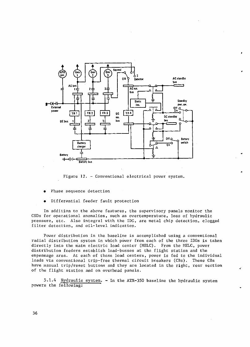
S-<~-U' I • I I • External power
DC bus
Blne~ ~
II!--tll ~ bus
AC standby bus
Standby
, •
Figure 12. - Conventional electrical power system.
• Phase sequence detection
• Differential feeder fault protection
In addition to the above features, the supervisory panels monitor the CSDs for operational anomalies, such as overtemperature, loss of hydraulic pressure, etc. Also integral with the IDG, are metal chip detection, clogged filter detection, and oil-level indication.
Power distribution in the baseline is accomplished using a conventional radial distribution system in which power from each of the three IDGs is taken directly into the main electric load center (MELC). From the MELC, power distribution feeders establish load-busses at the flight station and the empennage area. At each of these load centers, power is fed to the individual loads via conventional trip-free thermal circuit breakers (CBs). These CBs have manual trip/reset buttons and they are located in the right, rear section of the flight station and on overhead panels.
5.1.4 Hydraulic system. - In the ATX-350 baseline the hydraulic system powers the following:
36
~
..,
..
.:
..

-~
·s
"
~
"
• Primary flight surface controls
• Secondary flight surface controls
• Main and nose landing gears
• Main and nose gear doors
• Truck leveling (leveling of the MLG bogie)
• Nose wheel steering
• Brakes
• Miscellaneous jacks/door locks, etc.
The L-1011-500 hydraulic system is used as the basis for the ATX-350. Figure 13 is a schematic of the system. The hydraulics are arranged into four separate, parallel, continuously operating systems; A, B, C, and D systems.
Some of the design features are:
• Two independent systems assigned to primary flight controls exclusively without utility subsystems attached
• Two of the four systems never cross an engine turbine blade plane
• One system is excluded from each wing
• Centrally located service center facilitates rapid servicing and replacement of components
• Greater system flexibility in the arrangement of four systems versus three systems
Systems functions are allocated to balance the work load and meet automatic landing performance standards for Category III all-weather landing capability.
The four independent systems are designed for maximum flight control safety and performance and have the following capabilities:
• One hydraulic system inoperative - the aircraft control capability or rate of control is not reduced
• Two systems inoperative - the aircraft can complete its flight plan
• Three systems inoperative - the aircraft can maintain safe control throughout the normal operating envelope and land safely. One hydraulic system is sufficient to operate the flight controls
37

38
Left Crossbleed Isolation Valve
Priority AI I;; l Valve
Normal Accum.
Normal Brake Supply Valve
Right Crossbleed Isolation Valve
Press Reg
Alternate Brake Supply Valve
Engine Bleed Air
All
ITW-386
Figure 13. - Hydraulic system schematic.
"
~
..

-#
. ~
'. 4
.:>
"
If all three engines become inoperative, a ram air turbine deploys automatically and supplies power to the flight controls to assure a safe landing of the aircraft .
The duties assigned to each of the four systems are selected on the basis of maximum assurance that a single failure of a system will not impair the performance of the aircraft and that no reasonably conceived series of hydraulic failures would cause loss of control of the aircraft. All four systems are used in combinations to power the primary flight controls. The main pumps are rated 0.174 cubic meters per minute (46 gpm) at 20.7 MFa (3000 psi).
5.1.5 ECS and pneumatics. - The pneumatic system is similar to that for the L-1011 and provides compressed air for cabin pressurization, air conditioning, ventilation, engine starting, deicing, and turbine driven supplementary hydraulic power. Compressed air is supplied to the system from the propulsion engines, from the APU, or from ground support equipment.
The engine bleed air system is composed of three independent functionally identical subsystems, figure 14. Air from the intermediate pressure (IP) and high pressure (HP) stages is mixed in the ejector to give the required system pressure, a nominal 45 psig. Duct overheat devices limit temperature to approximately 500°F by turning off the HP air.
The air conditioning system, figure 15, pressurizes, heats, and cools the cabin. Three air cycle packs are used. The three are capable of supplying 0.6 PPM of fresh air per passenger and 0.6 PPM of recirculation air (50% recirculation). Cabin pressure is controlled by automatic outflow valves. The differential pressure is limited to B.4 psi. This provides a cabin altitude of BOOO feet at an airplane altitude of 42,000 feet. The altitude rate in the cabin is limited to 500 fpm going up and 300 fpm going down.
Hot bleed air entering the air conditoning packs is cooled by ram airflow over a primary heat exchanger, recompressed to higher pressures and temperatures and then further cooled in the secondary heat exchanger before expansion through the turbine wheel. During normal cruise at altitude, the heat exchangers provide sufficient cooling of the bleed air for cabin conditioning by modulating the ram air exit doors. During operation in a warmer ambient temperature, the ram air exit doors will open fully and, if necessary, the turbine bypass valve will close and divert bleed air through the air cycle machine for compression and then expansion in the turbine for further cooling.
5.1.6 Avionics. - The avionics suite is typical of a wide-body, international range aircraft such as the L-1011-500, and consists of the following subsystems:
39

Code:
Low bleed press High bleed press II I I « « I , b
No flow
Area in which overhealing is sensed ___ _
Eng 1 isln valv_
~'ml----"""-
Engine 1 ejector
i~I~~ ~ '/~ ·(f~.-----tI
'··~1: ..... _--L_ft wing anli·ice va lv_
~---_.../ L..::.:...I
I I I I
~'o I V . " ,
I . ---~ ~
I
I I
J
Cross bleed
~
To
Forward cargo heallXchanger
Eng
Isln valve
I
I
I I
8]0 I, . "
I
.. " "
Engine 2
~I:l:X:I:l:X:~~!2CJ:» Thrust reverser
.~,~
1------ 0; . .f
'.~
82 .
"'_-:ATM
" Cross bleed
~
I ~:~~ 1-- - -.: ... ~ ........ I
conlrol
Figure 14. - Bleed air control system schematic.
..
Engine 3 _jeclor
antHee valv_
\ ~ '- - --L..:.::W
I I ~=!~ 1- - - .. __ ./ I
ITW·380
.,
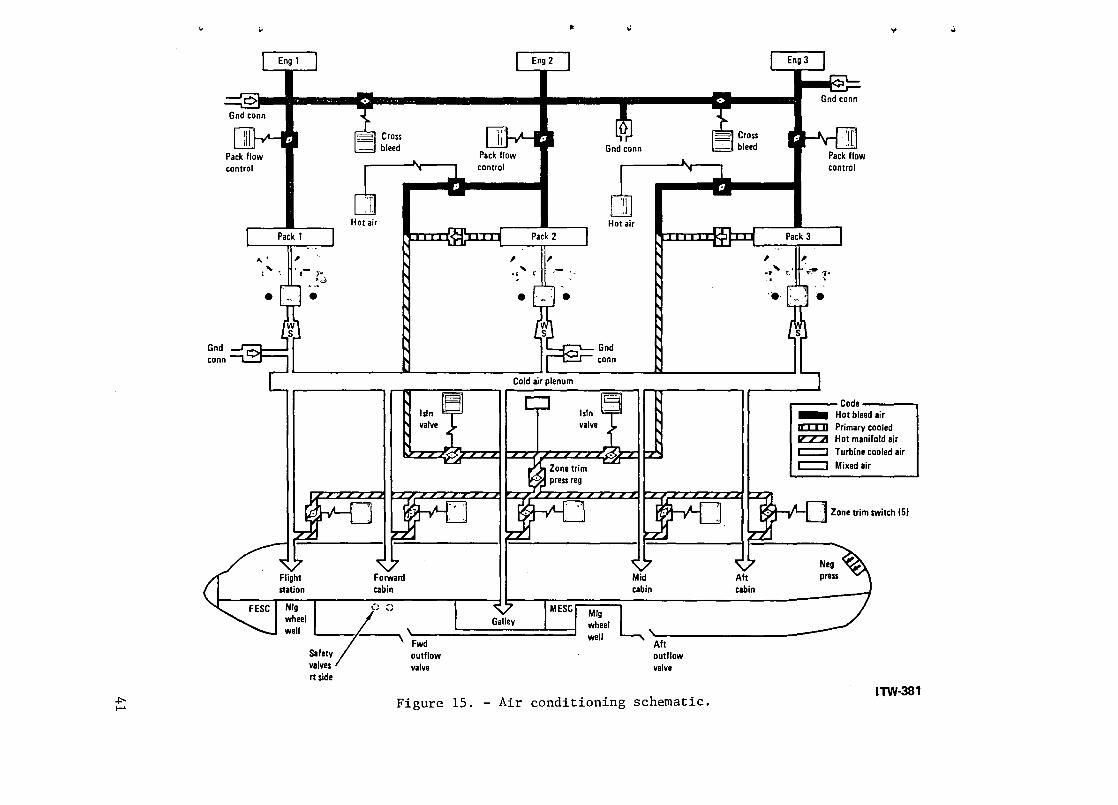
.po ~
~
Gnd conn
~
c::> Gnd conn
Pack flow control
... . ' Pack 1
, ',- )'. .. ~
e
rt side
Hot air
Cross bleed
Fwd outflow valve
Pack flow control
Pack 2
" ,'1'_ .. , r ~ .
e
.. ..
Gnd conn
Hot air
L,......... Gnd conn
Cold air plenum
Aft outflow valve
Figure 15. - Air conditioning schematic .
Cross bleed
cabin
Pack 3
Gnd conn
Pack flow control
.,.
, ~' " ; .~ "1 (. .~ ;'f ..
"e"
' .
r---- Code ----, _ Hot bleed air I[D]J Primary cooled IZZ2I Hot manifold air c=::J Turbine cooled air c::::::l Mixed air
IA.l-IL....D Zone trim switch IS)
ITW-381
...

42
• Communications
VHF transceiver (2)
5ELCAL
HF radio (2)
Intercom
Passenger services
Cockpit voice recorder
Note: The communications system was not subject to trade off in this study. Information is included for background and to suggest future integration possibilities.
• Navigation
Inertial navigation (3)
Flight management (2)
Omega
VOR (2)
115 (2)
DME (2)
Marker beacon
Heading reference system (2)
ADF (2)
Radio altimeter (2)
Ground proximity warning
Weather radar
ATC transponder (2)
• Primary Flight Control Avionics
Autopilot (2)
.-
c.
•
•
~"
..
....
.J.
, '3-
-1
'"
Air data system (2)
Instruments
The major avionics are mounted in equipment racks in conformance with ARINC 600 and are located in the forward bay below the flight station floor. Flight controls and autopilot are discussed in Section 5.1.2.
5.1.6.1 Communications: The basic communication systems are VHF, HF, a selective calling system (SELCAL), various audio systems, and passenger entertainment.
The VHF communications consist of two ARINC 716 tranceivers, two low drag blade antennas, and two sets of controls and readouts. The transceivers are Collins type VHF-700. Frequency coverage is from 118 MHz through 135.95 MHz in 50 kHz increments.
SELCAL relieves pilots of the radio monitoring task. The system has two channels, each of which can monitor calls on any of the VHF or HF receivers. When a properly coded incoming call is received, a display lights and a chime sounds.
The HF radio consists of two transceivers, a flush-mounted antenna, two antenna couplers and dual controls. The transceiver is ARINC 719, Collins type HFS-700. The antenna is located in the front spar of the vertical stabilizer.
Two intercom systems are provided, flight intercom and service intercom. The flight intercom has two channels, cabin intercom and galley intercom. The cabin intercom links the flight station and the ten flight attendant stations. The galley intercom links the galley and the principal service areas; fore, middle, and aft in the cabin. The service intercom links 20 major servicing areas throughout the aircraft for use during ground service'functions.
The passenger address system has speakers in the flight station, cabin, galley, and lavatories. Inputs are from the cabin hostess stations and flight station. Two-way interconnections are provided with the passenger entertainment system. The passenger entertainment/service multiplex system provides stereophonic sound, hostess call, and remote controlled reading lights and air outlets. This is a digital multiplex system.
A cockpit voice recorder, ARINC 557, is in the aft fuselage. It records cockpit conversation. A flight data recorder, ARINC 573, is also in the aft fuselage. An underwater sound pinger is attached to the data recorder. The system records 32 analog and 30 discrete signals involving altitude, speed, acceleration, control surface positions, and engine operation.
43

5.1.6.2 Navigation. - The navigation centers around the flight management system into which is integrated a triple inertial reference system, Omega, VOR, and DME.
The inertial system consists of three sensor systems, ARINC 705. The three separate outputs of the navigators are input to each of the two flight management computers and are also available for manual selection and display.
Performance management. - Performance management operates in cruise, climb, and descent modes. The cruise mode calculates optimum speed for a given altitude. The speed is then held approximately by automatic throttle, and more precisely by slight pitch variations. These pitch variations do not disturb altitude more than ±15m (50 ft).
The optimizing calculation takes into consideration' predicted winds and the desire for maximum cruise speed consistent with best fuel consumption or lowest cost. The system can display the optimum cruise altitude, taking into consideration length of flight and fuel to climb.
The climb mode automatically and continuously adjusts pitch attitude and throttle settings to give optimum fuel usage or cost. The optimum schedule considers various engine deratings, minimum fuel and minimum cost at the pilot's option.
A step-climb option provides
• A prediction of time to go to climb to a more optimum altitude
• A determination of whether the climb is worthwhile based on cruise distance remaining and wind
• Automatic control of the climb and transition to new cruise altitude when initiated by the pilot
The descent mode provides an optimum descent profile taking into consideration predicted aircraft weight at start of descent, temperature, cruise altitude and speed, desired descent speed schedule, altitude capture geometry, and the desired end of descent position, altitude, speed, and time.
VOR/ILS. - The VOR/ILS provides position and guidance signals to the pilots' displays, flight management system, and autopilot. Two VOR receivers, ARINC 711, and two ILS receivers, ARINC 710, are provided. Two remote manual controls are provided in the flight station as well as automatic control from the flight management system. Three dual antenna systems are provided; glide slope, localizer, and VOR. The VOR is Collins VOR-700, the ILS is Collins ILS-700.
DME. - Two DME interrogrator units, ARINC 709, are provided. Output to two radio digital distance magnetic indicators of the four digit type. L-band blade antennas are provided on the bottom of the aircraft.
44
is Two
...
·1
..
l'
..

-J
j.
..
J.
'"
a
HRS. - The heading reference system consists of two flux gate compass systems damped by the inertial system. The flux valve is accurately aligned to an indexing plate to permit rapid replacement without the need for a compass swing. The compass data is supplied to the inertial systems for initializing the alignment sequence, providing a signal for failure monitoring and for degraded mode operation.
ADF. - The automatic direction finder (ADF) radios are in accordance with ARINC 712. Two loop antennas and extended-range sense antennas with coupler are located in the bottom of the fuselage. The ADF is low and medium (broadcast) frequency operating in the 190 to 1750 kHz frequency range. The receivers are Collins ADF-700 the antennas Collins DFA-70l. The output is visual display only, with no input to the flight management system.
Radio altimeter/ground proximity system. - The altimeter operates with altitude above terrain from zero to 760 m (2500 ft). Two radio altimeters are provided, ARINC 707 Collins LRA-700. The two radio altimeters are independent except for a cross connection to prevent mutual interference. Failure monitors detect faults, activate flags, and signal the autoland system. The ground proximity warning computer is ARINC 594, Sundstrand 965-0376-070 . The ground proximity warning computer detects abnormal altitude and altitude closure rates with respect to the terrain.
Weather Radar. - The weather radar is an X-band transceiver, ARINC 70S. Two PPI indicators are provided for the two pilots. The antenna and associated waveguide assembly is in the nose radome. The radome is protected from lightning and erosion. The radome hinges allow one man to open the radome safety and service components within the radome area. Gain is automatically controlled on the basis of receiver noise level sampling. Antenna tilt is adjusted by a control accessible to both pilot and copilot. The operating modes are NORM., CONT., AND MAP. The CONT. mode provides iso-echo contour mapping to indicate precipitation density in storm areas. In the MAP mode, a change in the antenna beam provides a ground-mapping presentation on the indicators. The maximum range is selectable; 50, 150, and 300 n.mi. The antenna is stabilized in two axes using attitude signals from the inertial navigator. A ISO-degree forward sector is scanned.
ATC transponders. - Two transponders with altitude reporting capability, ARINC 7lB, are provided. Two L band blade antennas are provided on the bottom center line of the fuselage. The transponder can be set to Mode A, C (domestic identification and altitude) or Mode B (international identification and altitude). Control knobs and a code display are provided to enable selection of any of the 4096 codes for the A and B modes. An IDENT pushbutton allows the system to respond with the special position identification when requested. The transponders are Collins TPR-700.
Air Data. - This system provides two air data computers. The inputs are pressure from the pitot-static tubes, and total air temperature. The outputs and their corresponding range of measurements are:
45

Pressure Altitude
Altitude Rate
Altitude Hold
Computed Airspeed
Airspeed Hold
True Airspeed
Mach Number
Static Air Temperature
-31 to + 15 000 m (-100 to +50,000 ft).
o to ±110 m/s (0 to ±20,000 fpm)
o to ±305 m (0 to ±1000 ft)
50 to 450 knots
o to ±20 knots
150 to 599 knots
o . 2 to 1. 0 Mach
-99° to +50°C
The computers are ARINC 706 and provide outputs for the air data instruments and recorders as well as the flight management system, the automatic flight control, the stability augmentation systems, and the Mach/trim feel. The computers use digital computing techniques.
Instruments. - Flight instruments are standard electromechanical, conforming to ARINC 415-2. Dual instruments are used throughout. DC torquers are used in servoed instruments. An instrument warning system indicates malfunc~ .. tion and status of the basic attitude sensors and guidance systems. Warning is accomplished primarily through warning flags in each associated display or by retracting the display. Monitor coverage is continuous and automatic. No arming or resetting is required. Comparison monitoring is provided for the primary airspeed, attitude, and altitude systems.
5.2 ATX-150, 150 Passenger Transport
?2.1 Aircraft. - The advanced technology aircraft (ATX-150, figure 8, is a small commercial air transport for domestic service with stage lengths averaging 400 n.mi. Design and technology features are depicted in table IX.
Design parameters are shown in table VIII.
5.2.2 Flight control. - The flight controls on the ATX-150 are similar in concept to those on the ATX-350. However, because of the smaller size, greater use of manual powered controls is justified.
Pitch control is by cable control of two tabs (flying tabs) in the trailing edge of the two elevator surfaces. The two surfaces, left and right, are connected together by a through shaft. Separate cable systems are used for the right and left sides. Linked (spring) tabs aid the flying tabs in the elevator. Pitch trim is by moving the horizontal stabilizer with an electrically driven jackscrew. Two motors and electrical power sources are provided for the jackscrew.
46
..
!
.t
~
~

--J
',j.
.-"
.1
...
..
TABLE IX. - DESIGN AND TECHNOLOGY FEATURES, ATX-150
Aircraft type Transport
Engines Advanced technology 2 wing mounted
Wing loading 120 pst
Thrust to weight 0.32
Wing sweep 300
Aspect ratio 10
Structure Advanced composites
Wing Supercritical
TIC 1/12
GTOW 55 994 kg (123. 3611b)
Roll control is by 6 spoilers ahd 4 ailerons. The ailerons are controlled by separate cable ~stems, left and right, leading to flying tabs on the trailing edge of the aileron surface. The spoilers, which are also used in a symmetrical mode for speed brakes and ground spoilers, are controlled by cables operating hydraulic servo actuators. There is a separate actuator for each spoiler. Roll trim is by manual operation of separate trim tabs on each of the two outboard ailerons. A separate cable system runs from the cockpit to each aileron trim tab.
Yaw is by a two channel hydraulic boosted rudder. The two hydraulic servo valves are controlled by a single cable system from the cockpit to the rudder location. The same cable controls a flying tab for back-up to the hydraulic systems. Yaw trim is by a manual cable driven jackscrew acting on a trim-feel spring. The rudder authority in the powered mode is limited as a function of air speed by electric motor driven stops on the hydraulic servo valve.
The autopilot operates into the cable control system for each axis through limited authority electrical actuators. A yaw SAS mode is included in the autopilot, as is control wheel steering .
5.2.3 Electric system. - The design of the baseline ATX-150 electric system is similar to the ATX-350. The electric system is a part of a conventional secondary power system in which the engine bleed system and the hydraulic systems are major contributors to the power demands and services in the aircraft.
47

The primary electrical power is by three 80 kVA, 200 volt, 400 Hz, 3-phase constant speed drive (CSD) alternators. A generator is geared to each of the two engines and one to the auxiliary power unit (APU). The integrated drive generators (IDG) operate over a 2:1 engine input speed range and use presurized oil cooling and separate (dedicated) heat exchanger. This combination CSD and generator is installed and removed from the airplane as a complete assembly. The generators are normally run in parallel and paralleling occurs automatically. Current transformers sense the output current of each generator and cause the load controller to signal changes in CSD governor settings so that the generators are equally loaded during parallel operation. ,When the APU is operating, the load controllers cause the CSD's to match speed with the APU for balanced generator loads.
28 Vdc is derived from three 3 kW transformer rectifier units, and two 22 AH batteries provide emergency power. A static inverter provides 0.75 kVA 115V 400 Hz for emergency ac power requirements. Electrical distribution is conventional from a load center midship under the cabin floor.
5.2.4 Hydraulic system. - The hydraulic system for the ATX-150 is similar to the ATX-350 except that, since the flight controls can be operated manually, the extreme reliability (for safety) of the quadruple hydraulic system is not required.
The system includes 2 engine driven pumps rated at 20.7 MPa (3000 psi), 0.057 cm/m (15 gpm). Two electrical pumps of 10 gpm capacity provide back up. A ram air turbine provides back up hydraulic power for the all engine out condition.
5.2.5 ECS and pneumatics. - The ECS and pneumatic system for the ATX-150 is similar to the ATX-350 system except that 2 ECS packs, each of 41 kg per minute (90 ppm) capacity, are used. One of these packs using 50% recirculation can provide pressurization at maximum altitude.
5.2.6 Avionics. - Avionics for the ATX-150 is similar to the ATX-350. The equipment is ARINC 700 series as follows:
VHF radio (2)
Passenger address
Service interphone
Voice Recorder
Flight data recorder
48
..
..
I'
~
.'

.'1
. .1
....
'1
~
J.
Air data system (2)
AHRS (2)
Radio altimeter (2)
VOR navigation (2)
Flight management system, FMS (1)
Weather radar (1)
Ground proximity system
1LS (2)
Transponder, ATC, (2)
DME (2)
ADF (1)
Crash locator (1)
Autopilot (2)
Flight control monitoring system
Instruments
The major avionics are mounted in equipment rocks in conformance with ARINC 600 and are located in the forward bay below the flight station floor.
The communication functions are similar to the ATX-350 except that no HF radio, SELCAL, or passenger entertainment systems are provided.
No inertial navigation or Omega are provided. A dual high quality AHRS system and air data system provide inputs to the FMS for dead reckoning navigation updated by VOR arid DME. The reasons for these differences from the ATX-350 is the domestic, short-range nature of the aircraft.
Flight instruments are standard electromechanical. Dual instruments are used throughout. An instrument warning system indicates malfunction and status of the basic altitude sensors and guidance systems.
49

5.3 ATX-700, 700 Passenger Transport
5.3.1 Aircraft. - The ATX-700 aircraft, as depicted in figure 8 is a large subsonic double deck transport for domestic routes. The baseline is much like the ATX-350 except that it is larger, with four engines and a double deck cabin. Like the ATX-350, it incorporates advanced structural materials, advanced energy efficient engines, and a supercritical airfoil. The design parameters are shown in table VIII and Design Features are shown in table X.
5.3.2 Flight controls. - The flight control system for the ATX-700 is the same as the ATX-350 except that the actuators are scaled up in size and the wiring runs are longer.
The baseline aircraft has full hydraulic power controls, a flying stabilizer, and direct lift control. The primary flight control system includes controls for the horizontal stabilizer, ailerons, rudder, and spoilers. Geared elevators, driven mechanically by the stabilizer, improve the effectiveness of the horizontal stabilizer. The high-lift system consists of double slotted Fowler type trailing edge flaps and leading edge slats.
50
TABLE X. DESIGN AND TECHNOLOGY FEATURES, ATX-700.
Aircraft Type Transport 2 Deck
Engines Advanced Technology (4) Wing Mounted
Wing Loading 120 psf
Thrust to Weight 0.32
Wing Sweep 300
Aspect Ratio 10
Structure Advanced Composite
Wing Supercritical
TIC I 1/12
GTOW 337480 kg (744,168Ib)
~
[
...
10'

,',
-},
'1
J
»
j
The stabilizer is positioned by hydraulic servo actuators powered by four independent hydraulic systems; anyone of which, is sufficient for control of the aircraft. The rudder is powered by three of the hydraulic systems. The aileron servos are powered by all four sources so arranged that a different combination of three of the systems power the left and right ailerons.
There are six panels of wing lift spoilers on each wing - one set in front of the inboard flaps, and two more sets ahead of the outboard flaps which are actuated by servos powered by three of the four hydraulic sources. Various combinations of these panels can be operated, either symmetrically or asymmetrically, for supplementary lateral control, direct lift control, and for in-flight and ground air braking. The flaps and slats are each powered by two independent hydraulic sources, and each has an asymmetry-detection and protection system. Both high-lift systems are driven through gearing and spanwise torque tubes which, in turn, drive screwjacks to position the panels.
Pitch control and longitudinal trim are both provided by the flying stabilizer as opposed to previous longitudinal control systems using the sta-bi lizer surface for trim and elevator surfaces for pitch control. Dual-cable control runs are used, each capable of operating two separate dual-hydraulic servo valves, and four actuators which together position the stabilizer.
5.3.3 Electrical system. - The electrical system for the ATX-700 is the same as for the ATX-350 described in section 5.1.3 except that because of the larger volume and four engines versus three, there are four engine."driven generators of 125 kW each. The APU generator is also increased to 125 kW. The inverters and transformer rectifier units are the same size and quantity as on the ATX-350.
5.3.4 Hydraulic system. - The hydraulic system for the ATX-700 is the same as for the ATX-350 except that, because of the four engines and the increased weight of the main 1andin~ gear, an additional pump is added. All of the main pumps are rated 0.174 m (46 gal) per minute at 20.7 MPa (3000 psi). The ram air turbine is increased in size to 0.113 m3 (30 gal) per minute.
5.3.5 ECS and pneumatics. - The ECS and pneumatics system for the 700 passenger airplane is the same as for the 350 passenger airplane except that the capacity is doubled to maintain the 0.6 pounds per minute of fresh air per passenger. There are three air conditioning packs. Each is capable of supplying 210 ppm of conditioned air at sea level to 10 km (30 kfk ft) altitude.
5.3.6 Avionics. - Avionics for the ATX-700 baseline is similar to the ATX-350 previously discussed. The major avionics are mounted in the forward bay below the flight station floor. Because the -700 is for domestic rather than international use, the communications does not include HF radio, no Omega is provided and only two, rather than three, inertial navigation sets are provided.
51
.. 6. TECHNOLOGY SELECTION
To aid in the configuration of the various candidate aircraft systems a technology survey was made. A list of pertinent technologies was preparedr(135 technologies), each technology was researched and a short description written. The technologies were grouped by discipline: Avionics, Navigation, Software, Flight Control, etc. Each technology was then evaluated as to advantages and status, and a Matrix was prepared, table XI. In this table the reference number refers to the written description following the table. Readiness year is the estimated time when this technology would be proved to the extent that an airframe manufacturer would select it for a new aircraft. Priority (High, Medium, Low) is that recommended for NASA development efforts. The matrix table also notes the configurations on which each technology was used in the ASSET configuration evaluation.
6.1 Avionics
1 Standard Avionic Rack
A standard avionic rack offers a means for reducing production costs and maintenance. The standard is presently in transition between ARINC 404 and ARINC 600. ARINC 600 is quite close in concept to ARINC 404 and offers an improvement but not a final solution to the problems of ARINC 404 and 404A. These problems are (1) air is an inefficient heat transport medium, (2) air flow must be carefully adjusted to and within each LRU, (3) dirt in the air contaminates the electronic components, and (4) the large number of mating connections including electrical, coaxial, fiber optics, and coolant require precise tooling to provide for a plug-in LRU and inevitable lead to damaged connections.
These problems are more important to the military than to commercial aircraft because the electronics is a greater part of the system and the mission. Thus the military has been pushing for more advanced electronic packaging technologies. The standard electronic module (SEM) program makes the electronic module (card) the LRU and provides a standard rack for the cards. It is likely that the commercial aircraft industry will wait for advanced packaging to be developed by the military. Advantages are in weight, first cost, and maintenance.
2 Standard Avionic Modules
Standard avionic modules offer a means of reducing production costs and maintenance. This technology is closely associated with the standard avionic rack of item 1. Standard electronic modules (cards) could be built with standard circuits usable for many different equipments and with standardized interfaces, not only mechanical for mounting, cooling, and electrical; but also signal format for interfacing with other standard modules. The u.S. Navy
52
~
f
,
~-

U1 W
~,
" Q ... ..,
TABLE XI. TECHNOLOGY SELECTION MATRIX
I- ADVANTAGES ·1· STATUS I· CONFIGURATIONS-I
AVIONICS
STD. AVIDNIC RACK
STD. AVIONIC MODULE
SOLID STATE RADAR ANTENNA
FREDN COOLING
MISSION & MAINTENANCE RECORDER
COCKPIT ALERTING SYSTEM
FIBER OPTIC DATA BUS
BUBBLE MEMORY
LSI TECHNDLOGY
LOW LIFE CYCLE COST AVIDNICS
VOICE RECOGNITION
FIDDS
DIGITAL INTERFACE AVIONICS
ARINC 700 EQUIPMENT
NAVIGATION
INTEGRATED COMMUNICATIONS
GPS. GLOBAL POSITIONING SYSTEM
CAT AVOIDANCE
RING LASER GYRO
LASER ALTIMETER
CORRELATION VELOCITY SENSOR
4·D NAVIGATION
RADIATION AREA CORRELATOR
SOFTWARE
HIGHER ORDER LANGUAGE
AUTDMATIC CHECKOUT
ADV. VERIFICATION TECHNIQUES
SNEAK CIRCUIT ANALYSIS
4
5
x X
X
X
X X
10 I X I X
11
12
13
14
15 16
17
18
19
20
X
X
XIX
X
21 I X I I X 22 X
23 24
25
26
X
X
X
SOFTWARE RELIABILITY ANALYSIS 127 X
'WHY CHOSEN "WHY NOT CHOSEN
X X X X X X X X
X I X
X
X X I X X
X X X X
X
X IX X
X
X
X X X X
X I X X X X X X
X I I X X X
xix XIX X
X X X X
X
X X X
X
X
XIX X
X I 84 M
83 M
87 L
X 183 M 87 L
83 M
X 187 L X 82
82
xlxlxI881H
X I X I X I 90 1M 80 L
X 871 M 82 M
X XIXIX X 88 L
XI IXIX X 88 M
X
X
X
X
X
X
Xix
~ I X
X X
XIXX88L X I 80 L
82 L
XIXIXI
84
1
L
X I X ~ X :: ~
X I X I X X I X
X X
83 M X X
83 L X X
86 M X
81 X X
X I X 83 M X X
X
X
WWH
X
WWH
X
X
X
X
X
X
X
X
-; ~ '0
'%. "'c>
X
X
% '\ ~ \
14
14
14
14
REMARKS
CDST. WEIGHT. MAINTENANCE ADVANTAGES
REDUCTION IN COST AND MAINTENANCE
MAINTENANCE AND WEIGHT SAVINGS
ADVANTAGEOUS VS DIRECT AIR OR AIR COOLED PLATES
COST SAVINGS'
INCREASED RESPONSE TIME. MAX SAFETY'
EMI PROTECTION & HIGH DATA RATE NDT NEEDED
COST AND WEIGHT SAVINGS'
COST. MAINTENANCE'
LOWER MAINTENANCE COSTS'
INEXPENSIVE. LIGHT VS ANALOG INTERFACE DEVICES'
1.2.101 WEIGHT AND RELIABILITY OISADVANTAGES VS. STD. AVIONIC RACK"
X
X
DEVELOPMENT COST" LET MILITARY DD IT
BETTER PERFORMANCE
RISK. NO URGENT NEED"
COST. MAINTENANCE
NO PAYOFF VS. RADIO ALT."
NOT COST EFFECTIVE"
LESS AIR TIME. INCREASED RUNWAY PRODUCTIVITY
ND ADVANTAGES OVER ILS. MLS"
RELIABLE. COST SAVING'
RELIABILITY AND SAFETY'
SAFETY'
RELIABILITY AND SAFETY'

TABLE XI. - TECHNOLOGY SELECTION MATRIX (Continued)
,. ADVANTAGES ---'~Ir-'o--- STATUS -I' CONFIGURATIONS---t
~~ ~ CO ~
".0 ~ ~ 'f, <z. ~~ ~ CO~'1'~' ..
~ ~O ~~ .. ""0~'1'~",,-,,-$> ~ ~ %'% ~'%.~~ ~~~~a~ O,,-"'b~ ~ ~ ~ ~~~~O~<; ~~"'~'(-> ~ 0 ~ ~ ~ c':~~'S>~0~ "'~c:,.-$>~'1>CO ~ ~ «''S!~ ~ ~~~~"''O~.o«''''«''''~ 0 .... ~~~ ~~.,.~.o<;~""C?o"~<G>~~~~~'2> CO"" ~ ~ CO~'f ~ % ~ ~ ~ "7, ~ ~ ~ ~ ~ % 1- 1- 1- 1- \. ,,<1:.. %. \
fLIGHT CONTROL '1>-v.-~~",,~~~~~~<;:'~~~~~~~~~1>~ ~ REMARKS
DIGITAL fBW 28 X X X X X 82 M X X X SUPERIOR TO ANALOG OR NO MUX
TIME SHARE 29 X X X 83 L X X X 30 SUPERIOR TO FRED. SHARE
FRED. SHARE 30 X X X 85 L 29 INFERIOR"
AREAMUX 31 X X X X X X X 83 M X X 32
FULL MUX 32 X X X X X X X 90 M X X X 31
CONTROL CONFIGUREO PROPULSION 33 X X X X X 90 M X EFFICIENCY ADVANTAGE
OIRECT LIFT CONTROL 34 X X X 82 M X X FAST AND PRECISE CONTROL
SIOEARM CONTROLLERS 35 X X X X X X X X X 87 H X 36 SIGNIFICANT IMPROVEMENT IN COCKPIT ARRANGEMENT'
PEOESTAL CONTROllER 36 X X X X X X X X 90 M 35 WEIGHT ANO SPACE PENALTY VS. SIDE ARM CONTROLLER"
FAUL T TOLERANT COMPUTER 37 X X X X X X X X X 89 H X ADDED RELIABILITY AND SAFETY'
FAULT TOLERANT SOFTWARE 38 X X X X X X X 89 H X REliABILITY AND SAFETY'
CAT III A·B AUTOLAND 39 X X X 80 L X X X X X X X 40
CAT III C AUTO LAND 40 X X X X X 84 L X 39 PART OF 1990"S ATC SYSTEM'
DIGITAL SENSORS 41 X X X X X X 88 M X X WEIGHT AND RELIABILITY'
EMI & LIGHTNING TEST/ANAL YSIS 42 X X X X X 83 H X X X SAFETY'
X r- -- _.- . . - c- - -- --- ---_._------- .--HIGH PRESSURE HYDRAULICS 43 X X X X X 83 M X 73.82 MAINTENANCE PROBLEM"
TWO WAY MESH BUS 44 X X X X X 90 L COMPLICATED FOR PRACTICAL USE"
MULTIPROCESSOR FOR fCS 45 X X X X X X 83 H X X
ACTIVE CONTROLS
RelAXED STATIC STABILITY 46 X X X X X X X X 83 H X 52
RIDE IMPROVEMENT 47 X X 84 L X X COMES WITH ElASTIC MODE SUPRESSIDN
MANEUVER LOAD AllEVIATION 48 X X 80 L X X REDUCES STRUCTURE WEIGHT'
flUTTER SUPRESSION 49 X X X X X X 95 M ANAL YTiC KNOWLEDGE NEEDED FOR HIGH FRED"S IN 80's
ElASTIC MODE SUPRESSION 50 X X X 83 L X X STRUCTURAL EFFICIENCY' IMPROVED RIDE DUALITY'
CG AND FUEL MANAGEMENT 51 X X X X X 83 H X X IMPROVED PERFORMANCE
FLIGHT CRITICAL RSS 52 X X X X X 92 H X 46 FUEl SAVINGS
ADV SPOILER MODES 53 X X X X X X X 83 H X X
'WHY CHOSEN "WHY NOT CHOSEN
1';1. ..... -, ...

VI VI
, It. Ii "
TABLE XI. - TECHNOLOGY SELECTION MATRIX (Continued)
ADVANTAGES ---I--STATUS--I--CoNFIGURATlONS--1
SECONDARY POWER '\ REMARKS
DIGITAL LOAD MANAGEMENT 54 X X X X X 83 M X X WEIGHT AND COST SAVINGS
SOLID STATE POWER CONTROllERS 55 X X X X X X X X 84 H X
SOLID STATE POWER CONVERTERS 56 X X X X X X X X 82 H X X SYSTEM WEIGHT AND RELIABILITY'
SOLID STATE POWER SW'S 57 X X X X X X X X X X 83 H X X WEIGHT, RELIABILITY'
ADV CSDS 58 X 83 L 62 INFERIOR WEIGHT AND EFFICIENCY"
SAMARIUM/COBALT TECHNOLOGY 59 X X X X X X X X 83 H X X 81 ADVANTAGEOUS VS. MAINTENANCE COSTS FOR HYDRAULICS·
VARIABlE VOLTAGE/FREO. AC 60 X X X X X X X 83 M X X 62,63 ADVANTAGEOUS VS. VARIABLE SPEED CONS. FREO'
270 V DC POWER SYSTEMS 61 X X X X X 84 H X
VARIA8LE SPEED CONSTANT FREO 62 80 L
HYBRID 400 VAC/270 VDC SYSTEM 63 X X X X X X 83 M
AoV SEC. POWER 64 X X X X X X X X X X x I X 83 H
olST BUS POWER DISTRIBUTION 65 X X X X 82 M
elECTRIC ECS 66 X X X X X X X X 90 H
elECTRIC STARTER/GENERATER 67 X X X X X X X X 83 H
elECTRO THERMAL OE·ICING 68 X X X 80 L
elECTRO IMPULSE DE·ICING 69 X X X X X X X B2 M
POWERED WHEelS 70 X X X X X X X 85 M
elECTRIC BRAKES 71 X X X X X 86 M
NON. MOD. EMAS 72 X X 81 H
SEC. fl T. CONT. EMAS 73 X X 83 H
ADVANCED APU 74 X X X X X 84 M
ANAL YSIS/SYNTHESIS
MULTIVARIABLE OPTIMAL CDNT. SYN 75 x x LIMITED STATE OPTIMUM CONTROL 76 x x x x
x x
x x
x x x x x
x I : x x x x
60,62 1 PARTIALl Y USED
60,63
60,62 I PARTlALl Y USED
SYSTEM WEIGHT"
ADVANTAGEOUS VS. ADV SEC PWR.·
SYSTEM WEIGHT VS. BLEED AIR FUel SAVINGS"
SYSTEM WEIGHT'
RISK""
RISK"
NO HYDRAULIC SYSTEM REOUIRED'
LOW MAINTENANCE VS. HYDRAULIC'
LOW MAINTENANCE VS. HYDRAULIC"
HI ALTITUDE START"
76,77,801 COSH Y VS. LIMITED STATE OPTIMAL CONTROL
75,77,80
~
LUENBERGER 08SERVER THEORY 77
ADV. ReliABILITY ANAl. TECH. 78
x x x x x x
: I I: x x
,x x I x
x x x
x x
85
86
86
88 M
82
x 75,76,801 INFERIOR TO LIMITED STATE OPTIMAL CONTROl. PART USE IN FUTURE
RELIABILITY AND SAFETY'
ANAL YTIC REDUNOENCY
ADAPTIVE CONTROL
'WHY CHOSEN
'"WHY NOT CHOSEN
79
80 x x x x USED IN CERTAIN APPLICATIONS
x xlxlxlxI841L 75,76,771 PRESENT RISK. LIMITED USE IN FUTURE

TABLE XI. - TECHNOLOGY SELECTION MATRIX (Continued)
I- ADVANTAGES
DIRECT DRIVE HYDRAULIC ACTUATOR 81 X X
ELECTRIC ACTUATORS
STORED ENERGY ACTUATOR
ECCENTUATOR
82 X X
83 X
DYNAVECTOR ACTUATOR
INTEGRATED ACTUATOR PACKAGE
REMOTE ELECTRONICS
MODULATING CLUTCH
TOROIDAL DRIVE
WIRING
ROUND CONDUCTOR flAT CABLE
flAT CONDUCTOR flAT CABLE
PROGRAMMABLE WIRING
ADV. WIRE 1.0.
MASS TERMINATION
DISPLAYS
84
85
86
87
88
89
90
91
92
93
94
HUD 95
EHSI 96
EADI 97
ADV. WARNING/ADVISORY 98
x
x x x x x
---.... +I ... ·---STATUS "I- CDNFIGURATIONS--!
x x x x x x x x x x
x
x
x
x x x x
x x x x x
x x
X
X
X
X
x
x x X 83 M
X X X 90 H
X X X X 85 M
X X 83 L
x x X 83 L
x x x x x x x x x x
x X
X
X
X
x x
x x x x
x
83 L
X 86 H
X 84 L
X 84 M
82 L
82 L
X 84 L
82 L
X 82 L
x x
x x
x
x x x
X X X 83 L X
X 83 L X
X 83 L X
X 90 M X
REMARKS
82 MAINTENANCE PROBLEM (HYDRAULICS)"
86,43
82,43
82
DEVELOPMENT RISK"
LIMITED APPLICATION
RISK", WEIGHT"
HEAVY"
COOLING PROBLEM
MAINTENANCE PROBLEM"
RISK"
ADVANTAGEOUS VS. flAT CONDUCTOR flAT CABLE,INEXPENSIVE
EXPENSIVE VS. ROUND CDND FLAT CABLe-'
USED IN SOME CASES
ADVANTAGEOUS VS. CONVENTIONAL
USED IN SOME CASES
OECREASEO PILOT WORKLOAO'
DECREASEO PILOT WORKLOAO'
OECREASEO PILOT WORKLOAO'
MAINLY A GROUNO FACILITY
~C=D=T~I __________ . ________ ~99~-4 __ ~X~-+-TERMINAL INFO CDTI 100
__ ~ X
X X ... __ ~ X X X
90 ~t-4--+~~4--+-~X~---4----------------------------------~ 88 H X X 121
103
104
OECREASE PILOT WORKLOAO'
POWER PROBLEM IN OIRECT SUN"
WEIGHT"
LED 101
LARGE SCREEN COLOR CRT 102
LCD 103
flAT PANEL DISPLAYS 104
INTEGRATED CONTROLS·DISPLAYS 105 X X
ELECT. FLIGHT ENGINEERS PANEL 106 X
WEATHER DISPLAYS 107
HOLOGRAPHIC DISPLAYS 108
DOPPLER RAOAR SEVERE WX SYSTEM 109
'WHY CHOSEN
'*WHY NOT CHOSEN
X
X
X X 85 L
X X 80 H
X X X 85 M
X X X __ ~M_
X X X X X X X X 88 H
X X X 86 M
X X X 88 M
X X X X 82 L
X X X X 90 M
X 101
X 102
X
X
X X X
SUPERIOR TO LEOS
WEIGHT AND SPACE'
WEIGHT AND PERFORMANCE'
WEIGHT AND WORKLOAD'
SAFETY'
CHEAPER AND LIGHTER FOR HUD'
NOT AIRBORNE EQUIPMENT
•
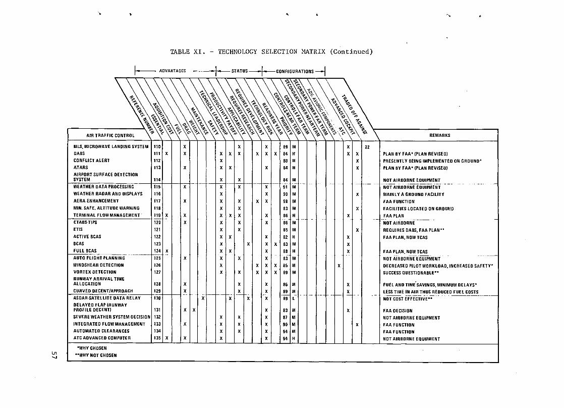
lJ1 -....J
-~ • .. -"
TABLE XI. - TECHNOLOGY SELECTION MATRIX (Continued)
I- ADVANTAGES
AIR TRAFFIC CONTROL
MLS, MICROWAVE LANOING SYSTEM 1110 x x DABS
CONFLICT ALERT
ATARS
AIRPORT SURFACE DETECTION
1111 X 112
113 x
.1. STATUS
x x x 1 x x x x
-!-CONFIGURATIONS --l
x x I x
x
89 M X I 84 H
80 H
84 H
SYSTEM 114 X X f'-- -~ !!"'-f---WEATHER DATA PROCESSING 115 X X X X 91 M
WEATHER RADAR AND DISPlAYS 116 X X 90 M
AERA ENHANCEMENT 117 X X X X X 98 M
MIN. SAFE. ALTITUDE WARNING 118 X X 83 M
TERMINAL flOW MANAGEMENT' 119 X X X X X
ETABS·TIPS 120 X X X
ETIS 121 X X
ACTIVE BCAS 122 X x
x x
. --~ --86 M 86j H
85 M
xii 82 H
BCAS ~23 FUll BCAS 124J X
AUTO FLIGHT PLANNING 125
WINDSHEAR DETECTlDN
VORTEX DETECTION
RUNWAY ARRIVAL TIME
126
127
x x I II x ~ x x I I x
x I X
83
1 M x 88 H
X 83 M
X X 85 M
AllDCATION 128 X
CURVED DECENT/APPROACH 129 X
ASDAR·SATElLITE DATA RelAY 130
DelAYED flAP (RUNWAY PROFILE DECENT) 131
SEVERE WEATHER SYSTEM DECISION I 132
INTEGRATED FlDW MANAGEMENT 133
AUTOMATED CLEARANCES
ATC ADVANCED COMPUTER
'WHY CHOSEN
··WHY NOT CHOSEN
134
1351 x
x I x
x
x
x x x I x I x I 89 1M
Xf-Tixt4-H} ~6 M
~ 89~+. 89 L
x x x x
x x x
x x x x x
83 M
87 M
90 M
94 M
94 H
--
x
'\ REMARKS
x I 1 22 X X PLAN BY FAA' (PLAN REVISED)
x
x x x
X
X
.-+----
PRESENTlY BEING IMPLEMENTEO ON GROUND'
PLAN BY FAA' (PLAN REVISED)
NDT AIRBORNE EQUIPMENT
NOT AIRBORNE EQUIPMENT
x I I MAINLY A GRDUND FACILITY
FAA FUNCTlDN
X 1 tACILITIES LOCATED ON GRDm!D
FAA PLAN .- ---.- -- ---------
NDT AIRBDRNE
X I REQUIRES DABS, FAA PLAN"
FAA PLAN, NOW TCAS
FAA PlAN, NOW TCAS
.-
-----NOT AIRBORNE EQUIPMENT
DECREASED PILOT WORKLDAD,INCREASED SAFETY'
SUCCESS QUESTIONABLE"
x 1 L I FUel AND TIME SAVINGS,MINIMUM DelAYS'
-.J---+-~- _ UESS TIM~ AIR_T~US~E~UCED_~~~STS_
x
x
NOT COST EFFECTIVE"
FAA DECISIDN
NOT AIRBORNE EQUIPMENT
FAA FUNCTION
FAA FUNCTION
NOT AIRBORNE EQUIPMENT

has such a program for standard electronic modules (SEM) with hundreds of SEM types cataloged and in operation. This shows promise but has been only moderately successful to date because of the rapid obsoleting of circuitry by advances in integrated circuitry. It appears that even with these problems the program will be successful and in time could be the basis for an industry wide acceptance of SEM for military and commercial airborne use. However, it appears that commercial aircraft will be following rather than leading the military and there is not much reason for tradeoffs at this time.
3 Solid State Radar Antenna
A solid state radar antenna which includes the power amplifier could be developed and could save weight and reduce maintenance costs. This system could also increase capability in that the beam would be agile and could be changed in pattern. This technology is of more interest in military than commercial applications because the military has more need for increased radar performance. It is likely that commercial airliners will take advantage of the maintenance and weight savings after the military has developed the technology for its performance advantages. This is not an important tradeoff at this time.
4 Freon Cooling
Freon-cooled racks for avionics could save weight over air-cooled racks by reducing the weight and space of air ducts supplying the rack and inside the rack. A refrigerant utilizing the latent heat of vaporization, such as freon, is a more efficient heat transfer medium than air. Also, since it is also a more efficient refrigerant (heat pump) than air, the same medium can be used throughout the system. If cold plate cooling is also used, the contamination of electronic components by airborne dirt can be alleviated. As in the previous sections, the military might be the most interested beneficiaries of this technology because of the typically larger electronic systems in military aircraft. An interesting tradeoff would be an integrated avionic system utilizing standard racks, standard modules, and freon cold plate cooling. Such a system would undoubtedly have significant weight and cost benefits but would be difficult to introduce by evolutionary methods.
5 Mission and Maintenance Recording
A mission recorder records the mission parameters; speed, altitude, fuel flow, etc.; for later use in reconstructing the flight. The parameters recorded and their later use and potential benefits are not defined at this time, however, more fuel efficiency, less structural stress, more passenger comfort might be obtained by computer analysis of the recordings and resultant operational changes.
58

~
<t
~
..
. ~
A maintenance recorder records maintenance parameters and their later use and potential benefits can vary from recording failures-only; to recording vibrations, load cycles, etc., for prediction of remaining life and estimating time before overhaul.
6 Cockpit Alerting System
A cockpit alerting system consisting of a set of warning lights has been incorporated on most aircraft for many years. However, as subsystems have become more complex and sensor subsystems more available, the number of warnings, cautions, and advisories desired have increased to a point beyond the ability of the alerting system. The lack of standardization in format from aircraft to aircraft also presents a training and effectiveness problem. The FAA has sponsored studies on the subject with the objective of optimizing and standardizing alerting subsystems for transport aircraft.
The philosophy is that warnings which require immediate response to ensure satety, such as ground proximity, should have a common aural signal with a vo:ice command, such as "pull up". Warnings which require immediate consideration but require additional analysis by the crew, such as engine fire, should have the same aural and voice warning plus a central visual display which gives the pertinent data required for the command decision. Alerts which caution but do not require immediate action such as reversion of autopilot to single channel, should have a common aural signal different from the warnings above, no voice command and a presentation of the problem on the visual display. Advisories such as crew call should have a different aural warning with an explanation presented on the visual display. The aural warnings should be repeated while the aural cautions and advisories should be one time only.
The above system, standardized in aural and visual format for the air transport community, will offer better response time, reduced training requirements, and maximum safety. This will result in lower costs because of reduced training and insurance costs.
7 Fiber Optic Data Bus
Signals can be transmitted over clear glass or plastic fiber as. modulated light. This works best with monochromatic light (lasers) and the bandwidth available (information rate) is larger than most electrical wires provide. The advantages are freedom from interference and weight, where equal
59

bandwidths are compared. Since fiber optics (Fa) has large bandwidths, the advantages show up where large bandwidths are required. This is mainly in multiplex (MUX) systems. Bandwidth is the limiting factor in the number of messages per second which can be accommodated on a bus. There are several problem areas. Tapping the Fa bus so that several stations may share the information requires devices which split the light energy into several equal channels without undue loss. This technology is a limitation at present. Also, the reliability of the transducers, light to electric and electric to light, are not good enough at this time. Both the communications industry and the military are working on these problems. Fa is worth far more to these two users than to commercial aircraft, therefore, we should limit efforts in Fa technology to applications and evaluations.
The advantages of a fiber optic system are as follows: It has a wide bandwidth; it is a nonelectrical method of transmitting and receiving signals through hazardous environments such as fluids so danger of electric arc or explosion are eliminated; it is immune to EMI and radio crosstalk, and its EMI output is greatly reduced. It reduces the interference between signals and wave degradation. The fibers are heat resistant, have a high tensile strength, and are nuclear radiation resistant. The savings in weight and space of the fibers themselves are great; however, the weight and space advantages disappear when the weight and size of armored fiber optic cable, couplers, terminating electronic equipment, mechanical strength, splices, and conjunctions are examined.
The main advantage, then becomes EMI immunity. Wire busses have little problem with EMI at lower speed, but problems may begin at 1 Mbps. A wired bus needs a coaxial system at high speeds whereas a fiber optic system remains equally efficient at high and low speeds. At the present time EMI is not a pressing problem but with the development of composite structure, where more interference will have access to the aircraft interior, a more immune system may be necessary.
8 Bubble Memory
Bubble memory is the storage of magnetized patches (bubbles) on a magnetically permeable film, usually crystal garnet or amorphous cobalt. The easiest configuration to produce is shift registers, meaning that large portions of memory, say lOOk bits, must be transferred from some other RAM into the bubble memory as a block of information. However, random access is feasible and should be available in the future. The bubble memory can have an order of magnitude better bit density than semiconductor memory, but several orders of magnitude greater access time.
Magnetic bubble memories show significant promise but will evolve as commercial technology independently of commercial aviation.
60
•
-<.,
.•
'~
,II
..
"
~.
9 LSI Technology
Large scale integration (LSI) technology involves putting a larger number of active devices in a single small package. Usually these devices are metallic oxide semiconductor field effect transistors (MOSFET). These devices lend themselves well to mass production of chips each with thousands of discrete transistors all connected together to provide a complex response, for example a complete computer on one chip. This technology has had a major effect on our civilization and the effects will continue as the technology is applied in more areas and research expands the capability. However, it seems that the support of commercial aviation is not required for the continuation of this expansion.
10 Low Life Cycle Cost Avionics
Low life cycle cost avionics is associated with standard avionic racks and standard avionic modules, items 1 and 2 of this section. It includes large scale integrated circuits, ceramic chip carriers, low-power devices such as CMOS where applicable, built-in test circuits and outputs, and lowoperating temperatures. The low-operating temperatures are obtained by low temperature heat sinks and by individualized design of each module to ensure that heat is transferred efficiently. The goal is a maximum case temperature of 60 v C for each semiconductor device. The low temperature heat sink is obtained by freon refrigeration either from the aircraft ECS or from dedicated vapor cycle units.
11 Voice Recognition
The use of digital electronics to interpret and take action on the spoken word shows great promise. The technology is making rapid progress and is even now practical in certain applications. It seems it will advance most rapidly in the military where the pilot workload is critical, for example in single seat fighters. For transport aircraft this technology will undoubtedly be used, as it is proven mature in the military, to reduce pilot workload and to give faster response in emergencies. However, it is not likely to happen in the next 10 years because the need is not urgent, for transport application, and the cost in procurement, maintenance, and risks is too high.
12 Fault Indication and Data Display (FIDD)
With the proliferation of avionics and avionic functions, the availability of small microprocessor/computers, and the specification of self-test features in most avionic subsystems, it becomes desirable and practical to provide a central system for systematizing the on-board testing procedures and recording the results for later maintenance use. The Lockheed L-I0ll has such a system called FIDD which records abnormal status indications within the flight
61

control, avionics, hydraulic, and engine systems. It appears that all transport aircraft of the future will have such a system for directing and recording self-test functions and recording out of tolerance system parameters as discreet deviations and in some cases as time histories. The time history recording will generally be as a result of logic associated with the short-term behavior of parameters.
13 Digital Interface Avionics
As additional tasks and functions are assigned to digital computers, it becomes increasingly beneficial to perform all information transfer in a digital manner. This trend is also addressed under the headings area MUX, full MUX and ARINC 700 equipment. ARINC 700 equipment and standard avionic racks and modules are and will be designed for interface with serial digital (MUX) bus, but will also have analog and nonserial requirements because many sensors and all switches are by nature not serial digital. There will be benefits in adopting sensors which either inherently interface with MUX or can be adapted with simple built-in electronics. It is desirable and possible to develop a switch (with built in MUX capability) for manual use, limit switch use, and automatic use. However, it is most likely that the MUX interfaces will develop naturally and gradually, first with area MUX and then with smaller remote interface units and built-in interface units as these devices become cost effective. It is not felt that research funds need be allotted to the development of these devices, but that standards be provided by proper authority, such as the ARINC and Military Standard publications. In this regard it is desirable that all standards, ARINC, Air Force, Army, and Navy, have as much commonality as possible.
14 ARINC 700 Equipment
A new series of specifications on specific transport avionics equipment has been released with the first user to be the Boeing 757 and 767 aircraft. The main new features of this equipment is conformance to ARINC 600 which defines digital interfaces (as well as analog) and new box sizes and cooling interfaces: ARINC 600 is intended to take advantage of technical and procedural advancements that were not available to those who developed ARINC 404/ 404A in providing mechanical, electrical and environmental interface information for air transport avionics black box design and installation. ARINC 600 defines a new rack to be used with the ARINC 700 series boxes and this defines the cooling air supply and new low insertion force connectors. New box sizes are defined, 1 MCU through 12 MCU. The ARINC 700 specifications define the details of the input-output electrical characteristics and pin numbers.
A new ARINC standard was needed, but the requirement that the boxes be compatible with old equipment resulted in little change. It is felt that ARINC 600/700 will last for at least several generations of transport aircraft but that major benefits could be obtained by a completely new standard. For
62
Ii'
.. '
...
.4

..
~
-II
..
..
,.
example, for the most part, the complete communication, navigation, data handling, display, and flight control electronics could be incorporated in one box/rack with provisions for replacing modules (cards) rather than boxes.
6.2 Navigation
15 Integrated Communications
Integrated communications is the technology whereby RF front ends, IF amplifiers, local oscillators, and frequency converters are bussed together so that these functional modules can be used, more or less interchangeably, for the radio requirements including radio navigation and identification. The objective is reduced cost and weight and increased reliability. The U.S. Navy is pursuing this technology under the title "Tactical Information Exchange System" (TIES). This technology could be applied to commercial aircraft but the payoff is better in military use because the communications requirements are more numerous· and rigorous. Therefore, it is likely that commercial aircraft will wait until the military has developed the technology.
16 Global Positioning System
The global positioning system is a hyperbolic navigation system depending on differences in time of arrival of signals from mUltiple satellites, nominally four satellites. The ephemeris of the satellite and time of day are transmitted from each satellite. A digital computer on the aircraft can then derive the position of the aircraft relative to the earth to an accuracy of +10 meters in three axes. This system is being developed for military purposes but can be used by commercial interests. The system could conceivably replace all radio aids to navigation: VOR, DME, ILS, MLS, and area navigation. The aircraft equipment is relatively cheap and light, $25,000 and 9 kilograms (20 pounds) is projected. However, the total system of satellites is quite expensive and takes a major commitment by the U.S. and its allies to develop. It appears that such expenditures by the commercial aircraft industry would be out of the question and that the use of such a system should not be relied upon. If in the future the system is developed and it appears that the system will be consistently supported by Congress, then it will undoubtedly be used by commercial aviation. A tradeoff to show the economic benefits of full use of this system for commercial aircraft would be useful and is recommended. The projected operational time period is 1990 •
17 Clear Air Turbulence Avoidance
Clear air turbulence (CAT) is similar to the turbulence encountered in thunderstorms except that it can not be detected by the cloud and rain structure. The magnitude and the frequency of occurrence is such that aircraft
63

damage or injuries to belted passengers is extremely unlikely. However, the potential for serious injury, especially to unbelted passengers, does exist and a large effort has gone into means for detecting or predicting CAT. Results of efforts to date indicate that reliable detection for avoidance is quite difficult and a large additinnal effort would be required for success, if attainable. It is likely that CAT cannot be detected far enough in advance for reliable avoidance. It is more likely that active flight controls will offer a sufficient measure of protection. For example, the aileron and spoiler controls can provide a 2g reduction in gust response in present aircraft (Lockheed L-1011). This is done by sensing accelerations and applying symmetrical aileron and spoiler deflections to counter the accelerations. Gust alleviation (ailerons) is provided to reduce structural cyclical loading and has a response of 3 Hz. Maneuver load control (spoilers) is provided to counteract pitch up moments at high angles of attack and has a response of 1 Hz. These responses and authority could be increased for CAT alleviation if necessary. However, the present methods, requesting that seated passengers use seat belts, are judged by the authorities to be adequate. Therefore, an evaluation of the worth of CAT alleviation methods does not seem warranted at this time.
18 Ring Laser Gyro (RLG)
Ring laser gyro (RLG) is the basis for the inertial navigation system (INS) on next-generation aircraft (Boeing 757 and 767) and as such will not need further government development funding. The use of RLG's can be carried further by using the RLG of the INS for the flight control rate signals. This is practical because the RLG is "strapped down" to . the airframe and thus the direct output is in body rates without coordinate conversion. The RLG was evaluated and traded-off in the study preceding this and shown to offer advantages in cost, weight, and maintainability.
Both the inertial navigation system and the flight control system use gyros and accelerometers as sensors. These have been separate in the past because the high reliability required for the FCS was not compatible with the high accuracy required of the navigation sensors. Advances in technology, especially laser gyros and strap down configuration, have produced navigation configurations in which the sensor outputs are as reliable as conventional FCS sensors. A relatively small amount of work remains in the architecture and software areas to assure that the FCS and nav functions are sufficiently isolated from each other. Benefits are in cost, reliability, and maintainability.
19 Laser Altimeter
Laser altimeter technology allows a more accurate altimeter than present radio altimeters. However, such an altimeter will not operate through heavy clouds or fog. The laser altimeter could be used at low altitude, say for
64
•
..
..
<,

"
~
4
~
~
the last 30 meters (100 feet) of a landing to give a very precise flare and touchdown. However, the present Autoland provides an adequate touchdown and therefore there is no basis for evaluating a laser altimeter for commercial airliners at this' time.
20 Correlation Velocity Sensor (CVS)
Correlation velocity sensor (CVS) technology provides a ground speed sensor accurate to 0.1 percent in absolute terms. This sensor is being developed by General Electric Company under u.S. Navy s~onsorship. It transmits a C band signal downward and receives the echo on antennas spaced about one foot apart. The magnitude of the return signals are digitized and a time correlation is performed between fore and aft antennas and left and right antennas. The antenna spacing divided by the time difference is the ground speed forward and left or right. The result is similar to a doppler radar although the principle of operation is different. CVS is cheaper, lighter, more accurate than a doppler radar and is not confused by wave motion over water. An attitude and heading reference system (AHARA) is needed with the CVS to provide a complete navigation system.
21 4-D Navigation
To understand fully the parameters of 4-D navigation, an explanation of 2-D and 3-D navigation must be given as they are predecessors and components of 4-D navigation.
2-D navigation is basic, providing latitude-longitude or the equivalent. This can be provided by omnirange (VOR), distance measuring equipment (DME) , inertial (INS), or other advanced systems such as the CVS of Section 2.6 or RLG of Section 2.4. 3-D navigation is the 2-D navigation and by some definitions includes the flight management system (FMS) to calculate the optimum path and guide the aircraft along this path. This technology is well established, however improvements in the area of cost, weight, and reliability could benefit the industry.
4-D navigation includes time as a controlled parameter and involves a 3-D navigation system plus the FMS which will calculate the optimum path to arrive at geographical locations at precise times and altitudes. The criteria for optimum can be minimum time, minimum cost, or minimum fuel. The most common criteria in the future will probably be minimum fuel. The electronic technology required to mechanize this system is well developed; but, the system design and application is somewhat obscure at this time. That is, how the capability fits into the air traffic control system requires more analysis, experimentation, and promotion. It has the potential for decreasing fuel usage and increasing traffic capability of an airport; however, rules, procedures, and operating methods for air traffic control must be established in coordination with other advanced air traffic control technologies. Advantages are less air time and increased runway productivity.
65

22 Radiometric Area Correlation
Radiometric area correlation (RAC) is a terminal navigation system developed for strategic missiles but sometimes proposed for approach and landing control for commercial aircraft. The system uses passive sensors in the 32 or 90 GHz region. The natural terrain radiates in these regions mostly as a function of temperature and emissivity thus the terrain has a unique signature which can be compared with stored signatures to give an accuracy of 10 meters or better at low altitude. If necessary in plain areas, the signature can be embellished by adding ground features such as paint or painted metal plates. The ground installation required is zero or minimal so the method is ideal for minor or temporary airfields. For the usual situation where ILS or MLS systems are already established the RAC is not needed; thus for airline use RAC should not be considered. However, for military or for general aviation operating into minor airfields, the RAC airborne equipment could be developed to low enough cost and weight to provide an instrument approach capability.
6.3 Software
23 Higher Order Language (HOL)
There are many HOL's now in use such as Fortran, Basic, and PLI.
They are of a higher order than assembly language and express a complete operation (such as let, erase, x) as a single command. The problem is that a standardized HOL is desired. It would reduce cost and errors because programmers would not have so much to learn and unlearn as they went from project to project. Having the HOL standardized and systematized can aid in training and concentrate experience. Some of the HOL's considered for selection as a standard HOL are: ADA PL-l, PASCAL, ALGOL 68, SPL-l, HALlS, LIS, TACPOL, CMS-2, JOVIAL J3B, JOVIAL J73, and CONTROL FORTRAN. SPL-l, TACPOL CMS-2 and JOVIAL (J3B and J73) are the DoD approved interim HOL for embedded computer applications. Each of these languages is a pseudo-standard for one of the military services. HALlS is a NASA language developed for space shuttle applications.
24 Automatic Checkout
Automatic checkout can involve both start up procedure and periodic inoperation checkout. The term does not usually include fault monitoring (which implies continuous error monitoring). However, the borders between auto checkout, fault monitoring, and fault tolerance are not always clear, usually they will all be used in a common fault tolerance effort. Automatic checkout in its simplest form, as a start-up or maintenance pr.ocedure, has
66
r
~I

..
,.
•
cI
I"
been used in avionics for years (the S-3A antisubmarine aircraft has extensive a~to checkout capability). With time, the procedures will become more complete and more accurate, the iteration rate will increase and logic will become more sophisticated. A point to be stressed is that the fault tolerance capability must be designed from system inception; it can rarely be added.
25 Advanced Verification Techniques
A significant problem exists in assuring that the software for a flight control system truly does what it is supposed to do, and no more, under all conditions. The problem prevails mainly because there are so many combinations of conditions which can exist. As a minimum, the software development effort must begin with a well defined design program with measurable completion criteria and include a second-party review as the work is completed. The program architecture must provide program modules capable of being verified individually, each with well defined inputs and outputs. The actual testing should include the following sequence: module testing, end-to-end verification (in a computer simulation); iron bird simulation (integrating the program with all other systems in the airplane); and flight testing.
Verification of total aircraft system software will always be a large effort requiring good people, a systematic and disciplined approach to programming, and extensive checkout in an iron bird .
26 Sneak Circuit Analysis
This problem is similar to that of advanced verification techniques of paragraph 25. The name is a carryover from analog circuitry, however, for analog circuitry the logic is usually far less complicated than for digital. Analog circuitry may be simulated on a digital computer and all combinations of conditions investigated quickly. The procedure is similar for digital systems except that the digital system is usually so much more extensive that all combinations cannot be investigated in a reasonable amount of time.
27 Software Reliability Analysis
Software as developed by a human programmer will almost certainly have "bugs" (errors) in it; Le., parts of it will not perform as the programmer intended. Therefore, a test program is always scheduled to find these bugs and correct them; however, its is almost impossible to test under all combinations of input data, system timing, and 'hardware failure. Thus when system reliability approaching 10-9 failures per hour is required, an appreciable part of unreliability must be attributed to software. Software reliability is different in concept from hardware reliability; software will not wear out and once repaired (debugged) will not fail again. Thus, in theory, as a software package is operated, and debugged, its reliability will increase to
67

approach 100%. However, in a critical system, such as flight control, we must ensure that any failures occurring during this breaking-in period are not catastrophic. The need for modernization and functional change will prevent a software package reaching 100% reliability through the maturity path. The assurance of 10-9 system reliability including software is a difficult goal requiring a substantial and serious effort.
Almost certainly the required reliability will be met only by using all of the following: (1) well trained programmers, (2) structured software architecture so that it may be understood and tested easily, (3) massive testing of software and hardware together, (4) redundant computations by different algorithms and/or at different times, and/or at different levels of complexity, and/or by different hardware architectures. Item 4 would include tests for reasonability and would allow graceful degradation to more simple algorithms, even to back-up analog systems.
The methods of analysis necessary to prove that the system meets the reliability requirements, are not clear at this time. It has .been suggested that the software and hardware be analyzed together using traditional hardware reliability analysis; i.e., fault tree logic and/or Markov logic with failure rates, on a per line or per module basis, estimated from experience with previous systems. This is an area requiring immediate analytical effort.
6.4 Flight Control
28 Digital Fly-By-Wire
Fly-by-wire (FBW) means that the control commands are transmitted to the actuators by electrical signals rather than by mechanical cables and push rods as in most present aircraft. The electrical signals might be analog or digital. True FBW would not have mechanical back-up although such hybrid systems would be used first until confidence is established in the FBW mechanization. FBW would have an advantage in weight although the major advantage is the increased performance and flexibility of modes and applications. The main reason that FBW has not seen major use is the requirement for both reliability and flight safety. Electronics are more likely to fail than cables and push rods; however, advances in solid state circuitry have made it feasible to have large amounts of electronic redundancy and failure monitoring so that FBW is now competitive. Although some analog FBW systems have been built, the major benefits will come in the digital systems where digital computers will be able to perform complex stability algorithms and redundancy and monitoring functions. The electronic technology is being developed independent of the aircraft industry, however, the advantages and applications for commercial aircraft are not well explored.
68
r
~

.,.
\~
1.
,
...
29 Time Share MUltiplexing
Various modulation methods can be used for a data bus. Time share multiplexing is the most common for use with digital computers. In this system the messages are sent serially, one after the other, from one or more sources. This method is the obvious choice for digital processors since this is the way the processor works - one step at a time but very fast. No research effort is required in this area.
30 Frequency Share Multiplexing
Frequency sharing or frequency multiplexing has been used for many years for telemetry and for telephone service. By this method continuous analog variables may be transmitted on many channels (frequencies), or many voice channels can be used with center frequencies 3000 Hz apart. This is not ideal for a digital processor since the frequency response per channel is less than desired for a computer: Frequency sharing is applicable to a fiber optics data bus in that FO has a frequency response of over 30 MHz and thus can carry two or more channels (for example, one in and one out) of serial data. This arrangement would be a combination of frequency and time sharing.
No research is required in the area of time sharing versus frequency sharing.
31 Area Multiplexing
The FBW commands could go to each actuator via separate wires (plural for redundancy and also because there are monitoring circuits, feedback circuits, and switching circuits in addition to the position commands) or mul-: tiple messages can be sent over one pair of wires. The latter method is multiplexing (MUX). MUX can be digital or analog, frequency or amplitude modulated, time shared or frequency multiplexed. There can be any number of wires (busses), shared in a variety of ways. Busses can be one-way or twoway. In each case, there must be a MUX-DEMUX function, that is, the input signal whether it is analog or digital must be put into proper format (code, signal level, time slot, identifying code, address, etc.) to go on the bus and be injected into the data stream at the proper time. At the other end, the receiving equipment must identify the messages and put them in the proper format for use at the intended equipment.
32 Full Multiplexing
In full MUX, the MUX-DEMUX units would be put at each utilizing equipment (actuator for example) whereas area MUX would put the MUX-DEMUX in an area to service a number of actuators. The full MUX takes full advantage of the wire reduction potential of MUX. Area MUX takes only partial advantage
69

but eliminates some problems of packaging electronics for use in restricted isolated spaces. It is thought, that for the near term, area MUX would be best. Then, when the electronics is improved and proven, the benefits of full MUX can be approached.
33 Control Configured Propulsion
There are numerous interactions between flight control and the propulsion system. Some are major such as the inlet performance as a function of angle of attack and side slip. Inlet performance can be considerably improved if considered as an integrated system with flight control. This is mainly of interest for high performance aircraft but many more subtle interactions are occurring in subsonic transports, and fuel and weight savings may be obtained by more precise control. For example, controlling engine pressure ratio is good for some flight conditions but might introduce instability in a Mach-altitude-hold flight control mode. Studies are needed exploring the interaction of the two disciplines and identifying configurations which would be more nearly optimum.
34 Direct Lift Control
Direct lift control is mechanized on the L-10ll aircraft using the spoilers extended eight degrees and modulating pIus or minus eight degrees. This system gives faster and more precise control because it is not necessary to rotate the airplane to get lift modulation. Present usage is in the landing approach, however it has been proposed that it also be used in the descent phase to facilitate precise arrival at a metering fix (4-D navigation). There is a tradeoff involved: direct lift control versus thrust modulation versus turning flight. This tradeoff is part of the TCV program.
35 Sidearm Controllers
The use of FBW without mechanical back-up allows use of smaller manual control devices in place of the conventional control column, wheel and rudder pedals. It has not been proposed to modify the rudder controls although the throw might be significantly reduced. The conventional control column takes up a large valuable space in the cockpit and might better be replaced by a hand (wrist action) controller in front of the pilot or to the side (sidearm controller). Such a controller has been effective and adequate in spacecraft and in the F-16 fighter. However, some experimentation, education, and an evolutionary approach might be required in introducing it to airline use. Benefits are in weight, reduced pilot work load, and in increased visible panel area for displays.
70
r
~,
t
'.
..)

j>
..
,
~
36 Pedestal Controller
An alternative to the side arm controller previously discussed (paragraph 35) is a pedestal controller. This is similar to the sidearm controller except that the hand (wrist action) controller is in front of the pilot and thus can be used with either hand. The disadvantage is that it takes up valuable panel view area when mounted at a comfortable height. Rudder action can be obtained by turning the handle about the vertical axis. Pitch is obtained by tilting the handle forward and back and roll is produced by tilting the handle left and right. This 3-axis control action is also available from the sidearm controller.
37 Fault Tolerant Computers
The fault tolerant computer and fault tolerant software will be discussed together. The major methods of making fault tolerant computers are using software for detecting errors, directing voting, and reconfiguring the system after a fault. On the other hand, software itself can have faults, usually unintended actions occurring in rare conditions not previously tested. At present. there are many approaches to fault tolerant computers: fault monitoring. comparison voting, redundant.hardware, redundant algorithms, and selfchecking algorithms. Each of these can be applied at various levels within the computer .
The simple approach is multiple computers with majority voting. The more sophisticated approaches use algorithms which are self checking, that is algorithms which perform the computation in several different ways thus utilizing different paths and portions of the processor and memory. It appears that none of the known ap~roaches are clearly superior, thus each designer uses his own compromise in system architecture. NASA has been sponsoring studies in this area and should continue to do so especially in evaluating system concepts to establish basic guidelines for design.
38 Fault Tolerant Software
Fault tolerant software is discussed in item 35 above with fault tolerant computers.
39 Autoland IlIA and IIIB
Autoland IlIA. IIIB, and IIIC are automatic landing systems which take the airplane to touchdown automatically, utilizing ILS signals. IIA takes it to· touchdown only, with the roll-out by visual reference to the runway. IIIB takes it automatically through roll-out also, with taxiing being by visual reference to the taxiway or "follow-me" vehicle. IIIC includes guidance in taxiing. The L-IOll is approved for Category IlIA and IIIB for British Airways.
71

40 Auto1and IIlC
Auto1and IIIC includes blind landings as in Category IlIA and in addition includes guidance in taxiing (see paragraph 39 above). not a strong demand for IIIC a1thpugh some ideas on implementation pursued, see section on Airport Surface Detection System .
. 41 Digital Sensors
IIIB, but There is
are being
It is possible to provide digital outputs from sensors utilized in aircraft systems: temperature, pressure, position, speed, gyros, accelerometers, voltage, current, force, angle of attack, etc. To the extent that this might come naturally or easily or give superior performance, it should be encouraged. However, in many cases even where digital output comes naturally the output must still be conditioned for input to a computer or MUX bus. In these cases, it is just as easy to go from analog to MUX as from digital to MUX. D to A and A to D converters are quite compact and cheap so it doesn't pay to put much weight or money into providing digital rather than analog output. In many cases, for example MUX or computer inputs, it requires less complex equip-
/'
(
ment to input analog than digital. This is because the analog signal is avai1- , able all the time whereas the digital signal must be interpreted and put into buffer memory until the MUX or computer· asks for input.
42 EMI/Lightning Test Analysis
The disruption of wired multiplex busses by lightning is a problem of unknown magnitude at this time. For metal-skinned aircraft, this problem has not been serious. It may cause dropouts; i.e., momentary loss of communications, but not catastrophic loss of the system. Composite skins must be protected by conductive additives otherwise they will be destroyed by lightning. It is felt that if the composite skin has a high enough conductivity to protect it structurally, then electronic circuits can be adequately protected by conventional methods such as filtering and nonlinear conductive devices. This, however, must be proven by extensive testing. Such testing should be undertaken and guidelines and analytic methods developed for design of electronic equipment for lightning protection. If protection for wired busses becomes difficult, then fiber optics will be more attractive and possibly mandatory.
43 High Pressure Hydraulics
There has been much effort expended in developing a 55 MPa (8000 psi) hydraulic system, using pressures roughly twice that of conventional systems. This system would reduce size of actuators, pumps, lines, accumulators, etc. Most efforts have been by the military because weight and space are more
72
;.
~
..

..
4.
~
r
critical to a fighter aircraft than to a transport. However, the benefits have not overcome the penalties'to date. The benefits are not as large as one might think, for example, doubling the pressure cuts the area and volume in half but the diameter to only 0.707. In addition, the walls must be made thicker and seals and leaks become a problem.
44 Two-Way Mesh Bus
The military 1553 bus is a 1 Mbps two-way bus and is being used in a number of applications. A single bus allows for many stations with each station communicating with all other stations. This system has not been used on civil aircraft because it is not needed at this time and because it costs more money both in equipment and integration effort. Simple one-way busses such as ARINC 429 and ARINC 453 are established as the commercial standard for the next decade. There are benefits to be derived from the two-way bus in terms of weight and flexibility but the reliability is questionable at present for flight critical use (FBW). It appears that the MIL 1553 bus technology will be mature and proven (by the military) by the time a two-way bus is desired for commercial transports.
The term mesh-bus architecture is sometimes used to denote an approach to a fault tolerant digital bus linking computers and peripherals. The system provides multiple busses between nodes. Each node services one or a small number of devices (computers, sensors, controllers, etc.). A fault tolerant processor establishes and maintains a communications network with services to all nodes. Software establishes the network by sending messages to the nodes which close switches connecting selected lines of the network until paths are established to all functioning nodes. The network derives its fault tolerance from the large number of available paths between nodes. The capability is maintained by the software which continually modifies the network to exercise all links. Efforts should continue to investigate concepts, although this particular concept seems excessively complicated for practical application.
45 Multimicroprocessor Flight Control Systems
New FBW systems (e.g., for F-16 and F-lB aircraft) use multimicroprocessors, but the concept can be carried much farther in breaking down and isolating functions to provide less weight and more reliability. For example, more parallel and self-check channels can be included. As another example, a microprocessor can be included at each actuator to handle much of the feedback, monitoring, and failure reconfiguration for that actuator (it may be a multichannel actuator). This subject is also discussed in the section on Fault Tolerant Computers.
73

6.5 Active Controls
46 Relaxed Static Stability (RSS)
Traditionally an airplane has been balanced so there is a negative load on the tail. This makes it statically stable, i.e., the forces are such that they react to counter a disturbance. However this results in increased drag because the wing and the tail are countering each other in the lift direction. If balance were such that the tail had zero or positive lift the drag (trim drag) would be reduced and fuel savings would result. The resulting instability would then need to be counter~d by a stability augmentation system (or an extremely proficient and tireless pilot). There are degrees of stability; as the c.g. is moved aft toward the neutral (tail zero lift) point the aircraft tends to oscillate but as the c.g. passes aft of the neutral point the control becomes divergent, i.e., a pull on the stick will cause a climb but the climb will continue to steepen until the stick is pushed forward. This situation requires a command augmentation system (CAS) with logic to know that when the pilot pulls on the stick the command must be followed by the reverse command of pushing on the stick (a stick pusher). This condition had already been encountered in many airplanes near stall and in swept wing aircraft in normal maneuvers where the wing tips stall and shift the aerodynamic center of pressure forward (pitch up problem). For the RSS airplane a full time SAS or CAS is required. The most practical mechanizations for the CAS is a digital FBW system. To take advantage of minimum .trim drag the craft must be approximately 6% unstable whereas the maximum a pilot can handle, even for a short time, is 3% unstable. Thus the CAS is flight critical. An active c.g. control system (pumping fuel to shift c.g.) is desirable in that it can keep the c.g. near the optimum point for minimum trim drag during cruise and assure that the aircraft is not too far unstable for landing. Advantages are a smaller airplane and fuel savings.
47 Ride Improvement
The passenger ride can be improved significantly by use of active ailerons, or other lift modulation, in the symmetrical mode. Such a system is now in use on the 1-1011-500 aircraft but more for fatigue load alleviation than passenger ride. 1arge high-altitude, high-speed aircraft such as the 1-1011 have an inherently good ride because the high-wing loading requires a large change in angle of attack to change lift. Small short takeoff aircraft flying at low altitude have poor ride characteristics because of the low wing loading and bumpy air. It is these aircraft which would benefit most from ride improvement.
74
I'
,,.0,
,.
..

."
I~
<#
.>
t'
48 Maneuver Load Alleviation
This subject is a part of the pitch up problem discussed in the section on RSS. The problem is solved by deployment of inboard spoilers, an active stick pusher, or a command augmentation system (CAS).
49 Flutter Suppression
Flutter is a vibration of panels or control surfaces caused by an oscillatory interchange of energy between kinetic and aerodynamic forces. It is divergent and destructive within a few cycles and is controlled by structural stiffness and/or viscous damping. The problem increases with speed because of the increasing aerodynamic forces and there is usually a threshold speed for flutter design. It has been proposed that flutter could also be controlled by proper control surface inputs thus reducing the structural weight required for stiffness. Such a solution would require far more frequency response than in present control systems and also would require more analytical know-how than presently available.
50 Elastic Mode Suppression
Oscillatory motions of aircraft structure can be occasioned by interchange of energy in the kinetic and elastic potential form. This usually occurs as a low frequency (1/2 to 2 Hz) in the wing structure and can be dampened by proper application of aileron control forces. The L-1011-500 aircraft uses active ailerons for fatigue load reduction. Approximately half of this reduction is static load and half is due to the elastic mode. This suppression also acts to improve ride quality. See the section on Ride Improvement.
51 Center of Gravity and Fuel Management
See the section on Relaxed Static Stability fo~ the need for center of gravity (c.g.) management. Presently, the implementation of such a system has not been considered (except for test aircraft and the Concorde supersonic transport). There are problems in sensing and computing the proper pumping sequence both preflight and inflight. These are design problems, not conceptual, and should be considered in applications of RSS. The advantages are in reduced trim drag and thus reduced fuel costs.
Fuel management is associated with c.g. management. With inputs of initial fuel in each tank, fuel flow measurements, quantity measurements, and load cell transducers in each landing gear, a computer can continuously monitor and check flow against quantity in each tank to give a more reliable and detailed accounting of fuel remaining and c.g. This can be carried further
75

to automatically use fuel from the tanks and transfer fuel, if necessary, to give the most fuel efficient flight within time, safety, and maintenance constraints.
52 Flight Critical RSS
Relaxed static stability can reduce drag up to 10%. This is because conventional aircraft are flown with the c.g. forward of the wing center of pressure (cp) thus requiring a down load on the horizontal stabilizer to trim the airplane. By moving the c.g. aft, either by loading or by shifting fuel aft in flight, the down load can be reduced thus reducing drag (trim drag). However, if an aircraft is operated with this aft c.g., it is unstable because a pitch up causes an increased angle of attack, an increased lift and, since the c.g. is aft of the cp, an increased pitch up. This unstable condition causes a loss in handling qualities and, if carried to the point of maximum benefit, the human pilot cannot control the aircraft. However, an electronic system, because of much faster sensing and response, can easily provide proper control. The problem with the electronic system is getting sufficient reliability. Since a failure might mean loss of the airplane, the electronics must be redundant to the point that the probability of complete failure and loss of aircraft is very low (less than 10-9 failures per hour). With the present state of electronic component reliability this means that a 4 channel (quad redundant) system is required with all the attendant fault monitoring and voting techniques. There is presently much research activity in the field of fault tolerant computers, fault tolerant architecture, and multimicroprocessor technology (paragraphs 25, 27, 37, 38 and 45). It is a diffcult problem but there are some such systems operating and it is expected that such reliability will be routinely attainable in the next 10 years.
Additional information on RSS is provided in paragraph 46.
53 Advanced Spoiler Modes
Spoilers have been increasingly used for many purposes: ground brakes, speed brakes, roll control, direct lift control, and load distribution. Some of these, uses require large fast excursions and some require very small, precise movements precisely coordinated with the other spoiler surfaces, other control surfaces, and sensor inputs. This multipurpose use is even more demanding on control systems than are the.traditional control surfaces. On the other hand, the spoilers are not as safety critical as, for example, the pitch axis and therefore offer an excellent opportunity for gaining in operational experience with sophisticated control systems and electric actuators.
76
,
,'"
.,,'
.. ..

..
~ I
..
~
I"
6.6 Secondary Power
54 Digital Load Management
For advanced systems it is projected that the management of the powergeneration system, and the loads in the aircraft, will be effected by a digital, or low-level logic, control system. In the former case, a serial rCM system, based on a MIL-STD-1553 or ARINC 429 data bus system, will be lIsed or, in small-commuter or short-haul transports, a miniature gage dedicated wire control may be used that provides the same features of the digital data bus control. In either case, it is projected that the management system will interface with solid state power controllers and hybrid remote power controllers that combine the functions of a relay and a circuit breaker.
The implementation method, applicable to the power-management and the load-management systems, are subject to trade analyses with respect to the operational philosophy and other details. Typically, discussions must be made around central processing or dedicated management systems, which make use of remote "smart" terminals and localized processing. These aspects have been significantly evaluated by Vought/LTV and specialized electronic houses. USAF and NADC have also funded a number of contracts, both in the area of SSPCs and digital data management. AFWALs latest report is AFWAL-TR-2l29: "Power System Control Study/Phase I and Phase II". This report and others define well the trades that are necessary to develop a practical and viable approach to digital data management and control.
55 Solid State Power Controllers
The development of SS~Cs is an interrelating technology which is complementary to the digital data management of the power generation and load control systems. The technical objectives, established in the late 1950s by the military and the aerospace indu~try, were to develop a range of SSPCs that could replace relays, power contactors and conventional electrothermal circuit breakers in current ranges from 1 amp up to over 200 amps. Such successful development would permit the remote control and/or remote resetcapability of SSPCs when they were located remote from the cockpit or flight station. Typically, in conventional aircraft, the power circuit breakers were not controllable and resettable from the flight station; as a consequence, if a circuit breaker tripped, on an overload or short circuit; the circuit was lost for the remainder of flight. This shortcoming led to the installation of many power circuit breakers in the flight station area, which would not otherwise have been necessary.
Under the stimulus of NASC, AFWAL, and U.S. Army programs, significant progress has been made in the development of solid state power controllers. NASA-Lewis has also been involved with the technology and with the development of very high current bipolar (transistor) and SCR devices. For the very
77
high currents (100 amperes and above) consideration is being given to hybrid devices in which the features of electromechanical relays and solid state relays are combined. For these designs, the mechanical contacts bypass the solid state contacts, so as to reduce the voltage-drop and heat-loss, which becomes significant in these high-current mu1tipo1e devices. The LockheedCalifornia Company itself developed a 28 Vdc 10 amp SSPC and this was reduced to a preproduction format, using two T03 cans. In this design the powerDarlington power-switch was in one can and the drive/control logic was in the other T03 can. In Phase II version of this SSPC,thedrive/10gic/monitoring circuitry was accommodated ina dual in-line flat-pack. For the future the adaptation of VMOS technology to the SSPC'appears rewarding. Presently, the military specification MIL-P-81653 is being used to control the development of SSPCs in the aerospace industry.
56 Solid State Power Converters
This technology of solid state power controllers (55), is utilized to a major extent in solid state power converters and motor controllers (87). Typically, converters convert alternating current. (ac) to direct current (dc) or dc to dc. The conversion can also be to a fixed constant voltage or. frequency or, the output voltage and frequency can be programmed, as required for motor-control. For power-supplies, the.main conversion requirements can be from 200 V 3-phase 400 Hz to 270 Vdc; 270 Vdc to 200 V 3-phase 400 Hz; variable-voltage variable-frequency (VVVF) to 270 Vdc; VVVF to 200 V, 3-phase 400 Hz; the process of dc to ac ( as in the case of 270 Vdc to 200 Vac) is actually known as "inversion".
In the technology of power conversion, rectifiers (SCR's) or bipolar devices are used to synthesize an ac wave from a dc power-source; or, to convert ac to dc, power-rectifiers are used. To develop constant-frequency from a variable frequency power source there are two candidate methods: "cyc10conversion" and "inversion" (dc link). In cyc10conversion, 400 cycle power is "demodulated" from a higher (variable) frequency wave by gating positive and negative groups of SCRs (on and off) in response tQ a 400 Hz signal generator. In the dc link system ac power is first rectified to dc and then it is inverted to ac. While the dc link has the advantage that it can operate from a nominally low (variable) frequency power-source, it is presently limited (by the power-transistors) to system capacities below 60 kVA.
~1any cycloconverters and dc link systems have been reduced to hardware status and to aircraft production installation status as in the case of the F--18, F5G aircraft. Generally, in new aircraft, the main. task, therefore, is to select the most suitable system from the standpoints of reliability, power quality, minimum weight, efficiency and thermal management.
78
,.,
'"
,.

..
" \
..
..
!"
57 Solid State Power Switches
As a result of the military programs in advanced aircraft electric systems and solid state electric logic, it is envisioned that in future aircraft all switching would be accomplished using solid-state devices that would replace the present manual toggle-switches and mechanically operated limitswitches. As a consequence, the aerospace industry has developed contactless switching devices utilizing magnetic proximity-detectors, wherein a metal (magnetic) member is passed in close proximity to an appropriate electrical sensor. By the use of magnetic-anomaly, or frequency-anomaly, detection circuits, the position of flaps, slats, landing-gear, doors etc., can all be determined passively. In the case of manually operated switches, photoelectric circuits as exemplified by passing a mechanical shutter between a light emitting diode (LED) and a photo diode (or photo transistor) can be used. Other passive detection circuits can utilize the Hall-effect or piezoelectric phenomena.
58 Advanced Constant Speed Drives
Conventionally, constant speed drives have been hydromechanical transmissions that have been interposed between a variable-speed engine and a generator for the purpose of maintaining a constant frequency. Typically, these CSD's have been bulky, heavy and costly in terms of acquisition and upkeep costs. Because of these problems, advanced CSDs have been developed utilizing a more compact design wherein the·generator and drive are integrated (side-by-side) in a single assembly. By use of modular component design and improved packaging technologies, the weight, volume and overhung moment of the CSD (on the engine pad) have been reduced. Through these new design/production techniques, the efficiency, reliability and life cycle costs of the advanced CSDs have also been improved.
59 Samarium-Cobalt Technology
Rare earth-cobalt magnets have high volumetric efficiency in that they possess a very high magnetic moment per unit volume, and they display highly stable characteristics in the presence of strong external magnetic fields. The measure of performance capability is defined by the energy-product, measured in Gauss-Oersted, which may typically have a number such as 20 x 106 : this compares with energy-product values of 5 to 7 x 10⁶ for permanent magnets, such as Alnico V. The samarium cobalt magnet therefore makes a quantum jump o~er the technology of permanent magnets and it is a technology that is still improving. For example, it is projected, in the near future, SmCo magnets may become available with energy-products in the area of 30 million (and more) Gauss-Oersted.
With the increasing availability of high strength permanent magnets, the weight, size, volume, and performance of electric motors and generators
79

can be significantly improved. For aircraft generators, the SmCo technology also offers particular advantages of rotor simplicity, since, in conventional generators, the rotor configuration consists of a .wound rotary exciter, integral diodes, a main wound field and a small PM generator. Additionally, because of the rotor heat dissipation there is a need to cool the windings and diodes, by passing oil through the rotor~ such oil must be contained by the use of rotating-seals. In the Smeo machine, all this rotor complication (and need for through-the-rotor cooling) can be eliminated, resulting in the production of a highly simple and reliable machine.
60 Variable Voltage/Frequency ac (VVVF)
In conventional aircraft power systems (using CSDs or VSCF technology) constant-voltage/constant-frequency power is generated. However, where a simple permanent-magnet generator (alternator) is used and it is driven by a variable-speed engine, the output voltage and frequency of the generator is proportional to speed. The voltage and frequency may, therefore, have a complete range of 2:1 but in flight it is nominally constant and so it is suitable for such loads a,s galley ovens, heating, lighting, deicing and ECS motor loads. For the avionics and other loads requiring high quality power, static power supplies (as described in 57 above) can furnish these relatively small amounts of power.
As a novel configuration of VVVF power, Lockheed ,proposed to NASA, the use of a primary 3-phase 400 V 800 Hz syste'm. This offered the advantages that motor speeds could be increased to 48,000 rpm (from the normal 24,000 rpm max of 400 Hz systems) and the higher (double) voltage reduced cable weight. It is a further synergistic fact that as the rectification of ac to 270 Vdc requires a minimum line to line (3 phase) voltage of 200 V, the 270 Vdc power can be still developed at 50% engine speed when the generator will also be down to 50% (e.g., 200 V).
61 270 Vdc Power Systems
This type of power may be used (as proposed by NADC) as a primary power supply in modern aircraft or, it can be used as an auxiliary power system; as may be required for specialized loads such as an all electric FCS. Again, in the first NASA/Lockheed study of advanced electrical/avionics technologies, the latter choice was made, since the 270 Vdc power was used almost exclusively for the all electric flight-control system.
It can be said that one of the attractive features of 270 Vdc, as a primary power supply was the fact that it was a simple alternative to the complex CSD installations and it did permit paralleling of multiple generators. However, in many aircraft there is a significant amount of 115 V 400 Hz equipment and so this equipment must be powered by separate inverters. Also,
80
""
..

,.
,'"
..
..
j
..
brushless dc motors cannot be powered directly by 270 Vdc so dedicated inverters (or motor controllers) must be used for all such motors. In large aircraft, the cabin-pressurization requirements alone can be very high and \vHl require large electric motors to drive the ECS compressors. The inverters for these motors would, therefore, be in excess of 100 kVA each. Similarly, there are many short time motor applications, such a landing gear, flaps, slats where a simple squirrel-cage.induction .motor would be a far more simple and reliable approach. Therefore, in balance, a primary ac system appears much more viable and practical.
62 Variable Speed Constant Frequency (VSCF)
VSCF is the electrical alternative to hydromechanical CSDs in that constant frequency power is derived from a variable frequency generator by electric power conversion technology. In the case of cycloconversion systems, it is necessary for the generator to be designed with a large number of poles and to be driven at hi~l speeds 10 to 20 krpm. This is necessary in cycloconversion, because the input frequency to the converters must be some 3 to 4 times the output frequency of 400 Hz. As a consequence generators operating over a 2:1 speed range will generate 1200 to 2400 Hz (or higher) frequencies. Also because of the electronic commutation, shielded power cables must be used to inhibit RFl problems. Notwithstanding these design constraints, VSCF provides :1 power system that has no highly stressed mechanical/hydraulic compnnents or pa~ts ~ubject to physical wear. It is theref~re, projected by the VSCF advocates that the reliability and life cycle costs aspects will be much superior to CSJ) technology.
63 Hyhrid 400 Vac/270 Vdc Syste~
This is a system that has had no formal R&D support, although it is one that merits such development because of potential advantages that reside in this type of system. The basic premise of the hybrid system is that it takes advantage of modern (samarium-cobalt) generator technology and static power conversion technology. Raw ac power is used wherever possible for loads such as heating, lighting, deicing, and many motor loads. Where 270 Vdc or special high-qual ity power is necessary, it is provided on an as required basis by dedicated power converters. This system is, therefore, an excellent compromise in that very large generators can operate with high transmission efficiency and the small amounts of dedicated power can be separately provided.
64 Advanced Secondary Power
In the conventional airplane the secondary power system consists of the followir.g:
• Engine bleed air: for functions such as deicing, ECS, thrust reversing, air turbine motor drives, etc.
81

• High pressure hydrauliG system: for operation of landing gear, flight control surfaces and other mechanical actuator functions.
• Pneumatics: derived from APUs, external power, engines, for engine starting, etc.
• Electric power: for all electric/avionic functions.
Each of the foregoing systems is being revised and upgraded for application in future advanced aircraft. Because of the unfavorable impacts of bleeding modern turbine engines, efforts are being made to minimize the bleed air demands. Similarly in the case of hydraulic systems, industry is considering the use of 8000 psi transmission pressures to reduce the actuator and transmission line weights. In the case of the electric systems, the aerospace electrical suppliers have been addressing VSCF and advanced constant speed drive technologies. However, in the latest considerations of an advanced secondary power system, the all electric airplane has come into focus since it results in a major simplification of the airplane. Simplification of the SPS comes about through the elimination of engine bleed-air, by the complete elimination of the .bleed-air ducts/hardware and by the elimination of the hydraulics and pneumatics. By the use of an all electric secondary power system, the producibility, productivity, reliability, life cycle costs and maintenance/logistics support aspects of the airplane are all improved. This type of advanced SPS may, therefore, be described as an all electric SPS and, more generally, as the all electric airplane.
65 Distributed Bus Power System
In conventional aircraft, power-distribution systems are normally carried out using radial feeders that supply power to load buses, located remotely from one or more main electric load centers (MELC). The MELCs themselves are normally supplied by power-supply feeders that come from engine-driven generators located in wings and empennage of the aircraft. With the advent of the all electric airplane, and the need to maximize the effectiveness of sophisticated load management (and power management) systems, the use of a distributed-bus system has potential merit, because it would obviate th~ need for separate radial feeders for all the loads in the wings, etc., electric loads in these areas could be tapped into a distributed-bus network via remote power controllers.
Up to this time, no distributed-bus system has been used in any aircraft, so much development needs to be undertaken to bring such a system into a practical and reliable format or configuration. A basic objective of the distributed bus systems is that it does not result in many breaks and termination points in the power feeders as they are routed through the airplane.
82
'"
lo:
(.

"'
,r
'i
..
. ~
..
66 Electric ECS
The environmental control systems are typically powered by engine bleed in nearly all conventional military and commercial aircraft. A basic reason for this is that up to this time, the power levels associated with pressurizing and air conditioning the cabin in large commercial (or military transport) aircraft has been beyond the capacity of typical aircraft-generators. However, with the design and development of large capacity permanent-magnet (samarium-cobalt type) generators, and the potential application of these machines to engine starting, it is now possible to consider an all-electric ECS. In these systems,.the bleed port provisions on the engine, the engine bleed hardware, and the ducting in the engines, pylons and wings can all be eliminated and replaced by a dedicated electric-motor compressor system.
As described in the previous and present NASA/Lockheed studies the all electric airplane, uses motor-driven (cabin) compressors, to meet the pressurization and heating requirements of the airplane, while the cooling needs are furnished by motor-driven freon compressors, or motor-driven bootstrap air-cycle machinery.
67 Electric Starter-Generator
In the past, electric starting of aircraft engines has been limited to helicopters and general aviation aircraft, because of the power-limitations of the electric starter-motor~. Normally, the engines in the small aircraft have been started with 28 Vdc starter-generators in the 150 to 400 ampere range. More recently, with the advent of the samarium-cobalt (permanentmagnet) technology, and the proliferating growth in power-electronics, it has become possible to consider static power-supplies that make it possible to operate SmCo "synchronous-generators" a.s "synchronous motor-starters;" these machines have the torque capability to start large engines, in the 50 to 60 klb thrust class, when the generator-rating are in the area of 150 kVA.
The mode-of-operation of the synchronous motor-starter has been described in this report. As described it is dependent upon the application of a programmable power supply to the stator of the SmCo starter-generator. A rotorposition sensor is used to commutate the electronic power supply in such a way that the voltage and frequency of this power source is increased in accord with input commands (from the flight-station/cockpit) and logic signals from the engine. The engine-start cycle is automatic, once initiated from the flight station, and the engine accelerates up to its self-supporting speed at a rate determined by the input logic .
68 Electrothermal Deicing
This form of deicing/anti-icing protection is applicable to wing surfaces, radomes, engine cowl-lips, and other exposed surfaces, that are subject
83

to ice-accretion. Electrothermal deicing as employed in past and current aircraft utilized a spraymat or an electric-boot approach. In the latter system a stainless-steel etched foil heater-element (or a woven wire element) is sandwiched between an inner and outer metal skin which is fabricated as an integral leading-edge assembly that is attached to the front spar beam. In the case of the spraymat, an insulating base of plastic is sprayed onto the surface to be protected and this is followed by a conductive metallized spray, such as aluminum, which forms the heater element; after curing, a top insulation layer is laid down, which is of a smaller thickness than the base layer, since heat must be transferred through it to the outside skin surface. Both types of electrothermal deicing systems have been applied to fixed and rotary wing aircraft.
Figure 16 is illustrative of the metal-boot approach, used in the Lockheed P-3 airplane. This shows that the heater boot is divided into upper and lower sections, each of which has a primary and secondary (runback) zone (e.g., sections C7/C15 and C8/C16 respectively). These sections are cyclically heated in a symmetrical fashion (left and right) with the electronic timer scheduling power to the secondary zones at less frequent intervals than the primary zones. The ON/OFF times to the heater zones are typically controlled as a function of outside air temperature and liquid water content.
C-B C-7
C-s C-6
84
Right Horizontal Stabilizer
C-16
C-lS
C-l3
C-l4
~1~11~1~
Vertical
Areas C·1, C·2, etc. are Energized Each Cycle in Numerical 0 rder
All Parting Strips are Energized at Same Time
• Overheat Sensor
1 ____ Production Break
Left Horizontal Stabilizer
C4 Co3
COl. C-2
Figure 16. - Electrothermal deice method.
....
.,.
•

'"
,"
1
..
..
69 Electroimpulse Deicing
This is one of the most recent approaches to ice protection; aside from the exploratory work now being conducted by NASA-Lewis on pie=o-electric deicin3 systems.
The electroimpulse system has its or1g1n in Russian patents, which describe the general principle of inducing an elastic deformation of a metal (aluminum) skin by eddy-current induction in the leading edge surface. The generation of the large eddy-currents, necessary to deform the skin, is normally by means of electromagnetic induction, effected by large (short duration) current pulses in the coils, located close to the skin structure.
The Lockheed-California Company has completed icing-tunnel tests on this deicing concept and these have established the power parameters and the effectiveness of this type of deicing system. Since, that time the LockheedCalifornia Company has built upon that experience and has developed novel/ proprietary methods of adapting the electroimpulse system to nonmetallic (composite) structures. Much work remains to be done, but the system does possess the attractive advantages that the required power levels (for deicing) are significantly reduced and the system is independent of outside air temperature .
70 Powered Wheels
This description is of the utilization of wheel-drive motors that are engineered into the aircraft landing-wheels to permit taxiing of the aircraft without using the engines. The incentive for the technology is to save fuel and to mitigate the brake and tire problems. Presently, the thrust of engines, during the idle-running conditions, are typically in excess of that required to meet most taxiing modes; as a consequence, it is necessary to ride the brakes in order to modulate aircraft speed. With powered wheels, the electrical energy would be provided by one or more onboard APUs which, in addition, to meeting the taxiing function would' also be used, at the end of the taxiing run, for starting the engines.
The technology of powered wheels is not new, but no work of significance has been accomplished to address the electrical and mechanical design aspects in any meaningful fashion. The mechanical adaptation and incorporation of the wheel-drive motors into the landing' wheels (either as wheel-integrated assemblies, or external drives) require detailed study and evaluation. Also, the electrical design of the motors, their type and their control are other important aspects to be addressed. The Lockheed-California Company has explored some of the unique control and implementation aspects of powered wheels and it is possible that there could be some novel proprietary multiple role uses of the wheel-drives that could increase the attractiveness of this drive-concept.
85

71 Electric Brakes
The application of electric brakes is being investigated as an alternative to conventional, hydraulically activated, brakes. The purpose is to eliminate problems (of hydraulic brakes) such as leakage, the requirement for a pressurized hydraulic supply and the danger of hydraulic-fluid fires, started by overheated brakes.
Electric brakes are in the category of powered wheels in that very little work has been accomplished on the design and the physical installation aspects, (other than some preliminary evaluations by Goodyear). Evidently, other tire/ brake companies such as Bendix, etc., will become active in investigating alternative electric-brake concepts when the interest in this technology increases. In these early design studies the electromechanical design and implementation methods must be critically evaluated. Among other things, it will be necessary also to assess the performance of electric brakes relative to smoothness of braking effort and their fast response characteristics. Some present implementation methods have considered a ring-type motor, in which the stator windings of the motor are carried in an annular cavity: When this motor operates it dri~es a high-efficiency ball screwjack that applies pressure to the multiple thrust plates.
72 Nonmodulating EMAS
A number of basic mechanical actuation functions have to be accomplished in military and commercial aircraft that do not require modulation or servopositioning. Such functions include raising/lowering landing gear, opening/ closing inlet doors, operating thrust-reversing mechanisms/clam doors and other miscellaneous linear/rotary actuation functions associated with cabin doors, canopy-operation, etc. These are categorized broadly as nonmodulating EHAS, since the mechanical output moves through linear or rotary limits, controlled by limit switches, etc.
For the airplane using primary ac power generation, most of the nonmodulating EMAS will be effected by means of ultra high reliability squirrel-cage induction-motors that will operate at single or dual-speeds. Where the powerrequirements are low (and the duty is short/intermittent) simple low-voltage, 28 Vdc, brush-type rotary/linear actuators may be used. Where the primary power source is 270 Vdc (and brush less dc motors are used), static power inverters must be interposed between the motors and the power source.
73 Secondary Flight Control EMAS
These actuation functions are differentiated from the nonmodulating (and the primary FCS EMAS) by the fact that although these services are not servopositioned, they may have multiple discrete-positions. Typical of such loads
86
"T'
"

"'
,I
"
•
..
loads are leading edge slats, trailing edge flaps, swing wings, tilt tails, h'eat exchanger cooler doors, and other nonmodulating mechanical actuation requirements.
In the implementation of the leading edge/trailing edge flaps, use is often made of a power drive unit (PDU), which is mounted inboard near the wing roots or in the unpressurized portion of the fuselage. This PDU normally drives torque tubes which are connected to screwjacks located on each flap and slat panel in the left and right wings. Control flap asymmetry detection/prevention, torque limiting, multiple position control and limit control are the additional features found in these SFC EMAS functions. Typically, for redundancy reasons two hydraulic motors, two electric motors (or a combination of an electric and hydraulic motor) drive into a mechanical dif~ ferential gearbox which connects to the left and right torque tubes via spline couplings. Brakes are also usually incorporated with each of the drives, so that in the event of mechanical failure, or power outage thst affects one motor, the remaining motor will drive the torque tubes at full torque/, half-speed.
74 Advanced APUs
Historically, APUs have been used in most commercial and military aircraft to provide self-sufficiency. In the case of the commercial airplane, this means that the APU furnishes ECS power (on the ground), engine-start power and electric power for the avionics/electrical loads. In the military airplane, there is no ground ECS requirement, so the APUs are used to furnish electric power to the airplane and for engine starting.
Typically, and particularly in the commercial airplanes, the APUs use" JP4 fuel to avoid any logistic-problems associated with the provisioning of different fuels. In the case of the military airplane, ,the APU may have to function as an emergency power unit (EPU) also: as a consequence, it may be powered by a monopropellant fuel such as hydrazine, which gives the airplane high-altitude start capabilities. A monopropellant EPU is used, for example, in the F-16 and other military airplanes.
The term advanced APUs, usually relates to the ongoing technology improvements which are being directed towards fuel efficiency, APU weight reduction, and improved reliability. These objectives dictate higher compression ratios, improved aerothermodynamics, higher turbine inlet temperatures, and methods of improving the overall cycle efficiency. A more esoteric approach to APUs, might involve the use of a JP4/LOX (liquid oxygen) unit, which would provide the APU with a high-altitude start capability: this would be most desirable in the case of the all electric airplane, the APU would drive a large electric generator only and there would be no pressurized air capability. It is pertinent also that in the all electric airplane, it would be used in the dual-role of an APU and EPU.
87

6.7 Analysis/Synthesis
75 Multivariable Optimal Control Synthesis
Optimal control theory, sometimes called modern control theory relates the state variables in matrix form and then optimizes the control to a stated criteria by solution of the Riccati equation. The number of sta'te variables e.g., position, altitude, temperature, pressure, etc., can be very large, say 40, and large matrices, say 40 by 40, are difficult to handle. Therefore, the drive is to reduce the number of variables handled in a single matrix. Multivariable optimal control attempts to work with the large matrix with all variables included. Limited state optimal' control and Luenberger observer theory are attempts to simplify the problem and reduce the number of variables.
76 Limited State Optimum Control
As stated in paragraph 75 above it is desirable to reduce the size of the state matrix. This can be done to some extent by judicious choice of variables. However, this choice and the proof of adequacy requires considerable insight into the system both from a mechanization and mathematical standpoint. Limited state optimum control theory is also useful for design of backup systems, where a full set of variable measurements is not available.
77 Luenberger Observer Theory
As stated in paragraphs 75 and 76 above it is difficult to obtain and handle a full set of state variables. Observability is the concept that, if any subset of the states of a system can be measured, then all other states can be determined. The observer is the hardware and/or software which accomplishes this task. The states of a system are the variables associated with the differential equations describing the dynamics of the system. Kalman formulated the observer concepts and they were later refined by Luenberger. The concepts allow the estimation of missing but essential state variables by use of other available variables. The estimation is by means of a filter like process.
78 Advanced Reliability Analytical Techniques
The use of multiredundancy in both hardware and software modules . increases both the need for and the difficulty of assessing overall reliability of the system.
88
,.
1"
"
'.
.. ,
"
,"
A variety of failure distribution models may be used to accommodate the nature of wear-out mechanisms in the system. The most common is the negative exponential or Poisson failure distribution model; a single parameter Rayleigh distribution may be used to model components with a linearly increasing failure rate. A second major element of the reliability model is the definition of the mode/state activity. For simple systems, this might take the form of truth tables or Boolean equations that can be conveniently mapped to probability distribution equations. System mode/state diagrams can also be used with graph theoretic methods for tracing and subgraph decomposition. Cut set/tie set analysis can be used to determine the event space of a set of states without enumerating them. The use of these techniques permits reduction of the model to a point where analysis becomes tractable.
For systems under consideration the foregoing models must be computer generated and analyzed and in addition a great amount of testing must be mechanized utilizing computer generated test inputs.
79 Analytic Redundancy
In developing the required reliability in the flight control computer system all approaches must be used. One approach, used on the space shuttle is redundant computations each performed by separate algorithms. These algorithms need not be of equal accuracy; degraded algorithms and degraded or optional sensor inputs may be used. These redundant outputs may then be used for check and/or voting.
80 Adaptive Control
Adaptive control usually refers to the changing of control system gains or logic in response to inputs from sensors or logic'outside of the control loop or as feedback from a comparison of desired to actual response. In a broader sense, a system which optimizes gains or logic in real time by means of optimal control theory, i.e., a solution of the Ricatti equation, is also adaptive control.
6.8 Actuation
81 Direct Drive Hydraulic Actuator
Control of a hydraulic actuator is by a hydraulic valve. This valve is usually controlled by an electrically operated valve controlling a secondary actuator which in turn operates the main hydraulic valve. One's first thought is to eliminate the secondary actuator and operate the main valve directly by the electrical motor. This has always been difficult because of the force required. The main valve requires high force because of seal friction and
89

because safety requires that there be enough force available to break chips which might lodge in the valve. There have been many attempts at designing an electrical actuator (motor) which could drive the main valve directly. These have failed either because performance was not adequate or because cost and weight were not competitive with the usual system. Some devices have been called direct drive which have an integral stage of hydraulic amplification.
Direct drive is claimed to reduce maintenance, increase reliability, decrease cost, and reduce quiescent flow. These are all worthwhile objectives but might be obtained with other advanced concepts, such as the integral stage of hydraulic amplification. Direct drive should be judged on its ability to realize the above advantages.
82 Electric Actuator
Two types of actuators which do not employ complete hydraulic systems (including housings, fittings, hoses, etc.) are electromechanical actuators and fiber optic actuators.
Electromechanical actuation (EMA) incorporates power-by-wire and flyby-wire systems to provide the flexibility and efficiency inherent to both systems. EMA uses electrical power directly and avoids the electrical to hydraulic power conversion penalty. It carries the inherent capability to convert a digital command to an analog force output within the actuation unit.
Two major actuation features are: closed loop position servo circuits using analog and digital techniques, and permanent magnet 270 Vdc motors using brushless commutation and rare earth cobalt magnets in the rotor assembly to achieve high acceleration and torque in a minimum space and weight. Rare earth dc motors are efficient because there is little or no heat generated in the rotating parts, no commutator brushes to wear out, and high strength permanent magnets provide high holding torque with low stator current. This motor offers a 16% improvement in acceleration capability, a 17% weight savings, and twice the operating duty cycle.
The functions performed by the EMA unit are: respond to command signal inputs from the aircraft flight control system, provide electric current and voltage control to an EM drive unit, match and apply the rate and torque output of the drive unit to the aircraft control surface.
One of the advantages of EMA's compared to hydraulic actuators is low maintenance; no periodic maintenance is required whereas hydraulic actuators require periodic checks for filter replacement, repair of leaks, and fluid level refills. There are reduced hazards with EMA's because there are no corrosive or flammable fluids involved.
90
....
r-
~

..
~
•
..
.. \
While the electromechanical actuator, as a separate unit, is approximately the same weight as a hydraulic actuator, EMAs show a weight saving when the whole EMA system (including power source and distribution) is compared to the whole hydraulic system.
Through the use of fiber optics, all electrical w~r~ng to the hydraulic actuator can be eliminated. The optical fibers are immune to EMI, EMD, and lightning but only if all other electrical wiring to the actuator package is eliminated. Fiber optics, in general, is discussed in item 7.
The Bertea fiber optic actuator is unique because the pulse train is read by an avalanche photo diode which accepts each of the optical pulses, transforms each pulse into an electrical signal and stores it in a logic circuit. Each iteration updates the memory.
Fiber optic digital actuators require further development to determine their overall viability.
83 Stored Energy Actuator
Recent studies have analyzed the use of different stored energy actuator concepts; a flywheel energy storage system has been shown to be the most effective. In comparison studies of a flywheel versus a battery for actuator energy storage it has been·shown that:
• The flywheel has greater charge/discharge cycle endurance life
• The flywheel delivers short bursts of energy at extremely high rates in relation to its size. A battery is limited by virtue of its internal resistance
• A flywheel is twice as efficient as well as being temperature . tolerant.
The." optimized disk flywheel stores 37% more energy than flat disk type and 86% more than a rim type when weight and diameter are the same. The reason for this is that the optimized disk stresses the material in the disk at a uniform level, thus allowing a higher speed.
A gear reduction box is required between the flywheel and load. The mechanical power package reduces the peak power demand imposed on the system thereby reducing the size and weight of the ac power generation system, but increasing the average power demand on the system •
Energy storage actuators using flywheels for energy storage have been demonstrated to be practical for application to aircraft but a practical method for introducing energy to and extracting energy from the flywheel has not been demonstrated for utility purposes. More research must be done to develop a high duration factor/minimum loss unit which is reliable and fail safe.
91

84 Eccentuator
The eccentuator consists of two structural members - a bent beam and an eccentric support bearing called a carrier. It can be used for conventional flight control surfaces, nose wheel steering, inlet and ramp cargo doors, etc.
The advantages of the eccentuator are: stiffness, application potential to thin wing structures, large mechanical gain, and long fatigue life.
A disadvantage of the eccentuator is the limited angle of deflection that it allows the surface to move through. To achieve optimum mechanical conditions, the beam bend should not exceed 7.5°. When the bend angle is increased to achieve a greater than 30° deflection of the surface, the unit has less mechanical advantage. Another disadvantage is that the eccentuator must be placed through a hole and connected directly to the spar which could cause a weakening in the spar structure.
85 Dynavector Actuator
The dynavector actuator combines a high-speed rotary motor with a reliable transmission to provide high torque, low-speed rotary power. be a hydraulic, pneumatic, or electric device.
simple It can
Two features make this actuator small and light; (1) its transmission reduces the high-speed input to a low-speed output in one step, using only two moving gears; (2) it has no physical motor - only a rotating force vector.
Some advantages include improved performance, decreased weight and size; the complete actuator including transmission and motor weighs only as much as the assembly of a conventional transmission that is equally rated. Simplicity lowers the cost, and increases reliability; low velocities between parts reduces wear. The large diameter of the dynavector could present a problem for thin wing installation, however.
This technology is not sufficiently advanced to show that it is cost and weight effective in the larger sizes, especially the electrically driven type.
86 Integrated Actuator Packages
The integrated actuator package (lAP) is a self-contained power transfer and control system. An electric motor and hydraulic system is used to transfer power from the aircraft electrical system to the flight control surface. Control signals can be electrical or mechanical. Electrical power is applied to these lAP's from the aircraft generators and converted to hydraulic power within the integrated package.
92
7
"

..
•
A
a ,
Power for the surface control is not derived from a central hydraulic system. The control is therefore invulnerable to loss of hydraulic power from damage to the hydraulic lines. The lAP generates less heat than the conventional constant pressure system and provides control power only on demand or where required. Electrical power lines are easily duplicated and will tolerate much more aircraft structural deformation and damage then hydraulic tubing. Circuit breakers protect against one component failure affecting other services. The lAP is a line replaceable unit which means maintenance and operating costs will be lower.
The disadvantages of an lAP are that the weight of the actuator is greater than the comparable hydraulic actuator it would be replacing. A good compromise, however, would be to have each lAP handling four to five control surfaces of the aircraft. The acquisition costs will also be high for the lAP.
87 Remote Electronics
Remote electronics as referred to for a f1y-by-wire system are those not located in the avionics bay or, more generally, not in the air conditioned area. Paragraph 32 discusses the problem with respect to multiplexing electronics; even more of a problem, however, is the remote power electronics for the electrical flight control actuators. This electronics is relatively large with large heat rejection rates, approximately 300 watts for a 5 HP .' controller. This equipment must be sealed to prevent moisture entrance and thus must reject all heat through the case. There are three basic ways to cool these electronics: by direct airflow over the case, by conduction to the airframe and thence to the air, or by a coolant loop either of fuel or coolant from the ECS system. Direct airflow is difficult because it would require a fan for operation on the ground. Rejection to the airframe is difficult because the airframe is heated to a high temperature by the sun in some situations. A fuel coolant loop is feasible but not desirable from a fire safety standpoint. A coolant loop from the ECS is probably least desirable from a cost and weight standpoint. Thus the selection of a cooling method is not clear at this time; it will depend upon size, location and heat rejection of each box.
88 Modulating Clutch
For flight control actuators the modulating clutch concept has always been attractive. The concept has been used extensively in small sizes for missiles but for larger sizes the heat dissipation has presented a major problem. This system uses a constant speed motor with a forward and reverse clutch connecting it to the load. The stored energy of the motor can then be used for transient response. The stored energy can be enhanced by a fly wheel so that the'motor can be sized only for the average load. The need is for a clutch which can tolerate large amounts of slip and transfer the heat
93

to a cooling medium. requirements. It is airplanes.
89 Toroidal Drive
The concept is best suited to small power, fast response doubtful that such a system can be mechanized for large
The toroidal drive actuator consists of two outboard toroids, one intermediate toroid, and two roller sets which depend on frictional contact between rollers and toroids for torque transmission. This actuator may be used with a continuously running motor, and therefore offers,special advantages in electromechanical servo applications where high frequency response is required. A continuously running electromechanical system is also capable of being used with flywheel energy in special mechanical servo power packages.
Within the toroidal drive category there are two types of toroidal drive actuators: differenti3l and straight. Differential toroidal drive is best suited to actuation of an FCS because it provides the quick response and change of direction that a modulating FCS (i.e., spoiler, aileron, canard) would require. With a constant speed input from a turning motor (the motor always turns in one direction) and with a very small input command to the steering rollers, the roller cage (where the fixed rollers are mounted) reacts (starts, stops, changes direction). The result is a mechanical actuator, or drive, which is quick to respond, can move an aileron quickly because it doesn't have to overcome its own motor inertia.
The straight toroidal drive consists of one set of rollers (steering rollers) and two toroids. It operates about a moving datum, i.e., the input and output speeds are the same. Output speed can be increased or decreased about this datum speed; but cannot be stopped or changed in direction; output can also be held at a constant speed if the input speed changes (speed regulator).
6.9 Wiring
90 Round Conductor Flat Cable
Many of the advantages and disadvantages of flat conductor cable (paragraph 91) apply.
Mechanical pressure connections can be made while obtaining the advantages of standardized tap fittings and conductor self-identification as in flat conductor cable.
94
1
~
A
~
-I
~
... ,
91 Flat Conductor Flat Cable
Flat conductor cable (FCC) is ideal for applications where high flexibility, weight and space reduction, and consistent electrical characteristics are required. FCC is made of solid rectangular conductors, usually bare or plated copper laminated between layers or sheets of high performance insulating material. To terminate, a low profile adaptor or spacer is positioned anywhere along the length of the cable where the connector is to be installed.
For signal and data transmission circuits, use of FCC allows conductor size reduction from the normally smallest allowed (No. 22 AWG) round wire conductor, for military application. Higher current capacity and more efficient heat dissipation is obtained due to larger surface area and a smaller insulation volume.
The capacitive reactance between the conductor and shield can be utilized to shunt interference from the conductor to the shield and ground.
Some disadvantages of a FCC system are that the flat cable exhibits a higher attenuation characteristic to a transmitted signal, and shielded flat cable exhibits a lower attenuation characteristic of the magnetic field between shield and conductor. Also, a re-evaluation of vehicle systems must be made or a new system developed when switching to a flat conductor cable system. New engineering, manufacturing, and quality control technology development is required as FCC is a somewhat new technique.
The weight savings of flat conductor cable over round wire cable is up to 80% and space conservation (up to 90%) makes it advantageous for use in congested and tunnel areas. Because of low material costs for high production cable fabrication, large quantity FCC costs should be greatly reduced.
92 Programmable Wiring
To facilitate w~r~ng changes incidental to equipment updates and/or system changes, programmable wiring is a candidate. The programmable wiring is usually accomplished by means of a wire program board which can be inserted into a (programmable) wiring terminal or junction. The Army calls such a junction assembly a matrix interconnect device. The programmable wiring terminals (junctions) can be located at strategic points in an airplane where there is a confluence of wiring, and where the wire program board can be used to provide specific interconnect relationships. This later capability also permits wiring harnesses, of flat cable, to be laid in an airplane before the wire addressing functions are known.
Certain hardware approaches have been taken, with the wiring programs implemented by printed circuit boards, wire wrap, termi-point or fuse-point wiring methodology .
95
Programmable wlrlng junctions have not found application in contemporary aircraft but it is possible that the utilization of such assemblies in future advanced transport could facilitate production wiring and retroactive wiring changes.
93 Advanced Wire Identification
This concept would number each run of wire in the conventional manner but the wire numbers would not be coded to a circuit but rather to location (terminations) in the aircraft. A digital computer, at the factory would then store the location knowledge along with size and type and assign the circuits to the appropriate wires. The wiring of the aircraft is thus designed and recorded by computer and the number of spares of any type in any location can be easily ascertained. Any changes are designed and recorded by the computer. This is quite similar to present practice except for the wire numbering scheme.
94 Mass Wire Terminations
This concept assumes that all wires are terminated in order on a termination board, by wire wrap or similar quick and reliable termination. The interconnection of wires is provided by an automatic digitally controlled wire wrap machine. Programming of the wire wrap machine is by the wire record computer noted in paragraph 93. This provides complete automatic interconnection for the vast majority of wiring and, if using the round wire flat cable (paragraph 90), the terminations are in large numbers at one time further reducing costs and chance for error.
6.10 Displays
95 Head Up Display
A head up display (HUD) displays alphanumeric data, symbology, or imagery superimposed upon the outside view of the pilot, thus enabling him to absorb information from the electronic data system without disrupting his perception of the outside world. This is especially necessary for a military airplane in an air-to-air or air-to-ground role. It can also be useful where it is necessary that the pilot concentrate on the outside view (such as in landing) while at the same time monitoring the electronic systems.
A HUD is expensive, weighty, and takes valuable space in the cockpit when compared to the head down display. However, recent advances in holographic lens systems as well as advances in electronic packaging and flat panel displays lead to optimistic projections. The cost, weight, and space will be reduced to the point where HUD's will be used on virtually all aircraft which have digital data handling and display systems.
96
/"
t)
..

~
..
"
<»
96 Electronic Horizontal Situation Indicator
The electronic horizontal situation indicator (EHSI) is a multimode display developed to present a better indication of the airplane's present and projected horizontal situation. EHSI mode selection, e.g.~ weather data on/off selection, is done from the flight deck mounted control panels. The traditional full compass mode of the EHS1 is available and will be helpful in initial flight crew transition from the conventional electromechanical HS1 display to the electronic HS1 display.
A navigation map mode can also be provided to reduce the use of hand held charts. When selected by the pilot, color coded weather information can be superimposed on the geopgraphic map display.
The EHSI can reduce required panel space because it incorporates the following functions into one display: MAG/TRUE heading, selected heading, desired course, ground track, drift angle, VORl and VOR2 course, to/from indication, lateral and vertical course deviation, ground speed, distanceto-go, navigation in use, wind speed, weather data, CDT1, and windshear data.
However, the EHS1 is best employed as part of an advanced cockpit system of multipurpos~ displays so that redundant displays are available for backup.
97 Electronic Altitude Director Indicator
The electronic altitude director indicator (EADI) consists of a CRT or flat panel display capable of presentin8 various symbols and alphanumerics, as well as a televised image of the real. world, and driven dynamically by the navigation and display computer. The EADI can reduce required panel space because it can be used for many modes such as takeoff-landing, cruise, and weapon delivery. Other symbols may be generated and displayed by mode selection such as 1LS window, airspeed deviation, altitude flight path, range, etc. The EADI, therefore, reduces the pilot's workload by reducing the number of displays he must scan.
However, like the EHS1 the EADI is best employed as part of an advanced cockpit system of multipurpose displays so that redundant displays are available for backup.
98 Advanced Harning Advisory
It has been suggested that an excessive number of discrete visual and aural alerts in todays cockpit causes an excessive demand on the information processing and memory capabilities of the flight crew. There is general agreement that an improved cockpit alerting system would minimize the time required to detect, evaluate, and correct impending failures. This system would also minimize the distracting effects on other flight crew tasks (i.e., aircraft control and communications).
97

The use of synthetic voice warning systems and programmable visual displays represent a potential solution to this problem. The advanced technology associated with these devices allows for potential operational advantages such as priority logic and flight phase adaptation. Before these systems can be incorporated into commercial aircraft, several operational and developmental issues must be resolved. Voice warnings may interfere with crew or ATC communications. Visual displays alone may be insufficient in attention getting capability.
99 Cockpit Display of Traffic Information
The cockpit display of traffic information (CDTI) could be ground derived and transmitted to the aircraft for display or could be generated on the aircraft from onboard sensors. CDTI is sometimes equated to collision avoidance but its use is thought to be broader than this. Some consider it as a replacement for the ATC but it is not that broad. Air derived CDTI can aid the pilot in evading collision courses far in advance, reduce cockpit load by quickly finding targets called out by ATC, aid in timing and spacing in the terminal area, and serve as a back up to the ATC advisory and resolution service (ATARS).
The ground derived CDTI was based upon U$e of the ground ATC radars and computers and the DABS data link to transmit the data to the aircraft. However, DABS ground facilities are not progressing according to schedule; also, air derived CDTI has become more feasible due to the adoption of TCAS-I and TCAS-II by the FAA. The air derived CDTI would operate in conjunction with existing ATCRBS and new TCAS transponders by means of both passive and active CDTI equipment on the aircraft.
100 Terminal Information CDTI
This system was first viewed as a metering and spacing aid to the pilot in the terminal area. It would thus prevent collision with other aircraft in the traffic pattern, but aircraft not in the pattern, such as small general aviation aircraft would still be a hazard and would be detected and displayed by the collision avoidance system. If the CDTI is aircraft derived the system is essentially the same whether in the terminal area or in cruise. If ground derived, the CDTI data might be transmitted only in terminal areas.
101 Light Emitting Diode
The light emitting diode (LED) display continues to be one of the dominant flat panel display technologies. Two-terminal semiconductor devices produce light by means of a radiative recombination of carriers in a forward based P-N junction; electrons are injected from a heavily doped N-region into
98
,-
•
'"

..
. '
"'
.-
..
...
the P-region of the device, and there recombine with holes. They are made to emit across the entire optical spectrum (though red is the most efficient color) •
LED displays, however, are inefficient because only a small fraction of the light, which is emitted from the junction in all directions, leaves the surface due to internal absorption and the high index of refraction of LED material. This lack of brightness, as compared to CRTS, may render them unsuitable for applications in high light environments. Their lack of luminous efficiency leads to high power usage and heat rejection. Therefore, there is a need for cooling. They have a short life and are bulky.
The main advantage of the LED display becomes its fast switching speed which leads to reduced crosstalk. In the future LED displays will probably be small, low resolution displays only.
102 Large Screen Color CRT
It is almost certain that there will be color displays in the future. Color cathode installed in a large number of new aircraft. have many advantages but are not viable yet; will be the display of choice in the ensuing
a large shift to mUltipurpose ray tubes are already being Competitive flat panel displays
therefore the central gun CRT 5 years.
The advantages of CRTs are high resolution, good addressability, high contrast, flexibility, color capability, and relatively low cost. The dis~dvantages are high voltage requirements, large volume, poor corner edge focus, limited useful life, and implosion hazard. The depth required in back of the panel is a function of CRT display area so it is unlikely that tubes larger than 7 inches will be used. A larger size would offer more flexibility by showing more than one format at a time, thus flat panel displays,. which have no depth to display area relationship, would have an advantage. Existing color tubes are capable of over 1000 lines in raster; this is thought to be adequate for the future.
103 Liquid Crystal Display
Liquid crystal displays (LCDs) are unique in that they emit no light, but rather reflect whatever ambient illumination is available. This is a significant advantage in high ambient environments, for it allows a high contrast ratio to be maintained at all times. Another advantage is that relatively low switching voltages are required for video intensity modulation and little power is consumed in an entire matrix of array elements. High resolutions can be obtained, and efficient use is made of the total panel area with 93% of the area being active in the light modulation process. The relatively slow element switching speed requires line-at-a-time addressing to achieve compatibility with TV data rates. For some applications this may be
99

a disadvantage; however it permits the use of multiple low-bandwidth video channels rather than a single high-bandwidth channel, and in applications where a digital scan converter is used, this approach may simplify the associated memory organization.
LCDs offer advantages where operation at very low voltage and power is required, also for large area displays or where readability in high ambient light is essential. LCD's have long life, 30,000 hours, and adequate resolution, 8 elements per mm (200/inch).
104 Flat Panel Displays
There are many types of flat panel display technologies currently being considered for use on aircraft today; plasma display panels (PDP's) ac thin film electroluminescent (ACTFEL), LEDs and LCDs (LEDs and LCDs are discussed in items 101 and 103 respectively). PDPs are the leaders of flat panel challengers to CRTs in performance. PDP manufactur~rs continue to increase performance and potential color availability with a decrease in cost. ACTFELS are low cost, large panels comparable to CRT's. They endure wide temperature variations during operation, have low power consumption, high brightness and luminous efficiency, and the ability to withstand high shock and high altitude environments.
Flat panel displays are built with a matrix addressable structure. The driver circuitry is often complex, cumbersome, and costly. Current efforts to alleviate this problem are being directed toward improved integrated circuitry, self-shifting of input on-signals (this treats each set of column or row electrodes as a shift register; data entered at one end shifted into its proper position), and internal decoding. Electroluminescent displays have the disadvantage that high voltage must be used to achieve adequate brightness.
Although flat panel displays are relatively new and expensive, the price will eventually decrease as this technology grows. FPD advantages when compared to CRT's are readability, compact-size, lower power consumption, inherent memory, and long life.
105 Integrated Controls/Displays
The term integrated controls and displays indicates the multipurpose use of displays and keyboards. The display is a CRT or similar element-addressable device so that any picture may be shown. The picture is generated by a special digital computer called a symbol generator or display generator. The display can thus show any format desired under manual or automatic control. The keyboard may include alphabet, numerals or other special keys but the keys will perform different functions depending on a mode selection. Usually the key usage is shown on the display in the form of a menu of selectable functions.
100
/
..
..

...
~
"
..
In some mechanizations the display can become the keyboard with sensing elements, for example an array of IR diodes, sensing the location of a finger on the display and the digital comput~r translating this into the proper command. In some cases mechanical switches are arrayed adjacent to the CRT so that the CRT can label the function of each switch while displaying the appropriate data for making switch selection.
These type of integrated displays have been used for a long time on military aircraft (P-3C and S-3A) and are being installed on commercial aircraft now.
106 Electronic Flight Engineer's Panel
The present flight engineer's panel consists of numerous subpanels which perform the following duties: check for fire or overtemperature, control engine bleed, control cabin environmental functions, control APU, monitor the fuel and electrical systems, and reinstate circuit breakers.
The electronic flight engineer's panel eliminates the need for numerous subpanels by using combinations of functions on single panels. A touch matrix CRT display acts as control switches, records maintenance and keeps a fault history. There is also a major reduction in circuit breakers in the flight stations.
A few advantages of the electronic flight engineer's panel are reduction in cost of ownership and flight engineer's workload. Also, the station will function at full capability with one computer and one display. The trend is to eliminate the flight engineer and thus the panel. The functions are then incorporated in the integrated controls/displays, item 105.
107 Weather Displays
This subject is also discussed in item 116. The display of weather on a multipurpose display started with onboard weather radar data displayed on a color CRT. The basis of radar identification of weather is the reflectivity of rain, hail, and snow. The color CRT is arranged to show the highly reflective areas successively in red, yellow, green and black. The airborne radar is usually coherent pulse doppler so a turbulence mode is incorporated in which color is proportional to speed. It is anticipated that if weather map data is transmitted from the ground it will be in the same format as the airderived data. In addition alphanumeric data on ceiling, visibility, wind shear, precipitation, and warnings can be presented.
101
108 Holographic Displays
Hologram technology has two applications to airborne displays; the holographic lens and the hologram memory. Large well-behaved lenses can be made on flat photographic film using holographic techniques. The resultant lens will have diffraction gratings spaced to alter the phase of incident light the precise amount required to focus. The main application of this technology is in head up displays (HUD) where large lenses are required to obtain the desired aperture and field of view. The lenses are cheap, light, and do not require much space.
The other application is in high density memory. A large amount of data for map or image presentation can be stored on film with relatively easy recovery and translation to electrical analog or digital format. Probably this application is more suited to military use than to the commercial airplane.
109 Doppler Radar Severe Weather Reporting System
Present ground weather radars do not utilize doppler processing and therefore lose a large amount of information. With doppler the speed and" speed-range of water particles can be measured at long distance. This will identify winds, turbulence areas, and wind shears. There are plans to increase the number of long-range doppler weather radars and the reporting and data processing to incorporate this information in to the National Weather Service reporting and forecasting services. Production on the new radar (NEXRAD) is expected in late 1986.
6.11 Air Traffic Control
110 Microwave Landing System
A microwave landing system (MLS) is being developed for first operation in 1990 with all large airports operational by the year 2000. It is a time reference scanning beam system operating at C band (5 GHz). It facilitates variable glide path and curved approaches in order to conserve air space, reduce noise, save fuel, and avoid obstructions. MLS can coexist with the present instrument landing system (ILS) and can be installed in locations unacceptable for ILS because of terrain or multipath problems.
The basis of MLS is a narrow beam projected from the ground and moved (scanned) at a known rate. Separate beams are used for azimuth and elevation, The azimuth and elevation angles are obtained by noting the time of passage of the beams, range is obtained by DME techniques and synchronization is provided by an omnidirectional signal. Provisions are made for a third scanning beam for flare and a fourth for back azimuth guidance for go-around. DME, elevation,
102
~

I'
J
and flare data are updated at 40 times per second, azimuth at 13-1/2 times per second, and back azimuth at 6-1/2 times per second. R&D is scheduled for completion in 1983, first operation in 1990, and general usage is scheduled for 1995. The progress and funding toward this goal has not been impressive, possibly because there are several alternatives confusing the issue:
• Do nothing, continue to use I1S
• Use RNAV and I1S
• Use GPS
Since I1S is already used for prec~s1on landings, the advantage of M1S is the ability to save fuel by allowing multidirectional approaches. However, RNAV or GPS could also perform this function. GPS has the potential for also providing precision landing capability.
111 Discrete Address Beacon System
The discrete address beacon system (DABS) requires a change over from the present ATCRBS transponder to a transponder which in addition to providing a beacon for surveillance radar use can accept a digital data string in the interrogation signal and provide a digital data string in the reply signal. The aircraft can thus be selectively interrogated and given messages from the ground and reply with messages unique to that aircraft. It is compatible with existing ATCRBS beacons and can be gradually introduced. The system will be expensive because new ground and airborne equipment will be required, thus budgeting will be a major problem which might delay the implementation of DABS.
112 Conflict Alert
Conflict alert is now used in some terminal control centers and is planned for incorporation in more terminal and en route centers. It automatically analyzes all aircraft tracks in real time for possible intersecting tracks and automatically alerts the controller. The controller then relays the information to the aircraft. This feature predicted the intersecting tracks in the San Diego PSA crash and alerted the controller. The alert was ignored because the aircraft reported visual contact.
This technology is here, and only waiting funding for wholesale incorporation into the system.
103

113 Automatic Traffic Advisory and Resolution Service
The automatic traffic advisory and resolution service (ATARS) is a collision warning and conflict resolution service for use by ATARS equipped aircraft. This capability is being developed concurrently with DABS and will use the DABS data link for transmission of ground derived separation insurance information. If traffic conflicts are not resolved in a predetermined time, by the basic ATC system or independent pilot actions, the ground based computer will issue maneuvering commands, via DABS, directly to the aircraft involved. ATARS is scheduled for first operational use in 1984 and is predicted to be in general use by 1988.
114 Airport Surface Detection System
Most large airports have such a system at present although most are deficient in coverage, reliability, resolution, and usability. Present systems consist of a simple low power Ku or Ka band radar with a rapidly rotating antenna on top of the control tower. Some present day systems are quite adequate, London Heathrow, for example, has an excellent system because of modern radar equipment and fortuitous location. All airports could have equally good surface radar if reasonable money were spent for modern radars and displays. A further extension of this system could be considered; the tower presentation could be data linked to the airplane on the ground so that the pilot might more promptly and reliably follow the controllers directions. The data link could be either analog, using existing TV equipment, or digital, utilizing existing UHF receivers and a computer composed format transmitting only the scene changes at high rate (5 times per second).
The technology is available, good equipment is available off the shelf.
115 Weather Data Processing
The prOV1Slon of up-to-date weather data to aircraft can reduce the effect of one of the major causes of delays and accidents; weather. The approach consists of automation of weather observations, manipulation of large masses of observations in computers and the automatic dissemination of predictions to the appropriate locations. FAA is developing an Automatic Weather Observation Station (AWOS). A Limited Aviation Weather Reporting Station (LAWRS) is under development jointly by FAA and National Weather Service (NWS). The use of pulse doppler radars is being investigated for detection and evaluation of thunderstorm activity.
116 Weather Radar and Displays
Cockpit display of weather information is'a system envisioned to provide the flight crew with data regarding storm cells, turbulence, and other types
104
f
"
..

,
..
'"
..
of weather information in conjunction with both en route and terminal flight procedures. This information would be a compilation of data from surface and satellite observations, terminal forecasts, pilot reports, and other sources. The data would be assembled on the ground and uplinked to aircraft requesting the service via DABS. The data would be combined with other flight path information and would require no additional display capability.
117 Automated.En Route ATC System Enhancement
The automatic en route ATC system (AERA) will provide better accommodation of flexible, fuel-efficient profiles, increase ATC productivity, reduce historic causes of system errors, increase ATC service availability, and reduce the potential for pilot error.
AERA provides the following functions:
• Automatically plans conflict-free, fuel-efficient profiles for aircraft operating in positively controlled airspace .
• Generates ATC messages needed to execute the planned profile and assure aircraft separation.
• Delivers ATC messages via a data link or VHF voice channel.
AERA protects against system failure by producing a coast capability and backup clearances and will be compatable with the backup systems such as DABS, ATARS and BCAS. Ground based computers will automatically perform most of the routine ATC planning and control functions under the active management of a traffic control specialist.
The productivity increases sought in AERA imply an increased traffic load per controller therefore, the impact of system failure on smooth traffic flow and safety will be much more severe. Reliability of hardware and software will be critical; backup procedures will be more complex; and human factors considerations pertaining to these backup procedures will be more important.
118 Minimum Safe Altitude Warning
This item refers to safe altitude as determined by the ground ATC system taking into account the position of the aircraft, position of obstructions on the ground and the altitude of the aircraft. Present altitude warning systems utilize radar altimeters and thus are accurate for collision avoidance only on relatively flat terrain. Other approaches would be terrain-following radar types which look ahead of the airplane and predict terrain contact; and stored map types which predict contact utilizing stored terrain data, the navigation system (DME-DME) and a radar altimeter. The advantages of the
105
ATC method are obvious; no equipment required on the aircraft. Most of the facilities are already available on the ground. The major portion to be added is computer programming. Voice communication for warnings will place an added load on controllers. The DABS data link will allow automatic warning without controller intervention.
119 Terminal Flow Management
This item is usually considered as applying to the descent and approach phases with a time at a metering fix, 20 to 50 nautical miles from the terminal, being specified from the ground. This system is now being applied at Denver and Dallas-Fort Worth, and results in a smoother traffic flow with fewer holding actions. As discussed in the section on AERA, the principal of metering and spacing should be applied in the future to the complete flight, even to the extent that a landing time is guaranteed before takeoff. The subject is also discussed in the section on 4-D navigation.
120 Electronic Tabular Display System - Terminal Information Processing System
Electronic tabular display system (ETABS) is being developed as an aid to improving controller productivity at the ground based en route control centers. There are twenty of these centers in the continental United States. They process flight plan information on all controlled aircraft. At present controllers store and change information for each flight. ETABS will eliminate the need for controllers to handle these paper flight strips and will improve the controller/machine interface. This will decrease cost and improve safety.
Terminal information processing system (TIPS) is similar to ETABS but is for the terminal controller. It will compute and assemble information on each aircraft in the terminal area, including conflicts with other aircraft and obstructions and present this as tabular data and visual and audio warnings. This is an inherent part of the terminal controller facilities and all the technology is available. TIPS will decrease fuel costs and increase safety.
121 Enhanced Terminal Information Service
The enhanced terminal information service (ETIS) would provide digital information pertaining to airport conditions such as ceiling, visibility, altimeter setting, active runway, runway winds, warnings, etc. This would be transmitted by request over the DABS data link and could be selectively filtered to eliminate items not of interest. This service is presently recorded voice and is called automated terminal information service (ATIS). The mechanization of ETIS is not difficult provided DABS is available. ETIS will decrease pilot workload and thus will decrease cost and improve safety.
106
r.<
&

'*
...
If
..
..
122 Active Beacon Collision Avoidance System
The active beacon collision avoidance system (BCAS) is under development with FAA sponsorship for use outside of ground based ATC surveillance coverage for collision avoidance. It makes use of the air traffic control radar beacon system (ATCRBS) or (in the future) the discrete address beacon system (DABS). ATCRBS beacons are now required on most aircraft operating in the United States. A transmitt~r is added to the BCAS aircraft which allows it to interrogate all ATCRBS equipped aircraft. The reply allows the distance and altitude to be determined for display and avoidance commands. Since this is an active system and will thus add to signal clutter, it must be carefully controlled by the FAA and its introduction will depend on such controls being developed. Advantages will be in reducing pilot workload, thus decreasing cost and improving safety.
123 Passive Beacon Collision Avoidance System
This system is similar to the active BCAS except that it is for back-up collision avoidance in controlled areas and thus is not allowed to transmit but rather listens to the ground interrogator and the aircraft responses • From the difference in time of arrival and knowledge of the interrogator location and rate of rotation, the geometry can be solved to yield bearing and distance to all aircraft within a 10 mile radius. This system is not actively being pursued by the FAA at this time since it is felt that ground radars and computers, with DABS as an uplink, can adequately guide aircraft to avoid traffic and collision. However, the budget required for complete automation on the ground and for the DABS system will probabiy cause delays in implementation plans. This puts passive BCA8 in a feasible low cost alternative position. If the equipment is satisfactorily developed, airliners can display traffic information in the terminal area for back-up route planning and collision avoidance; without the need for extra equipment on other aircraft or on the ground.
124 Full Beacon Collision Avoidance System
Full BCAS is both active and passive BCAS together to provide back-up collision avoidance in both low-density traffic areas and high-density traffic areas. The comments of both passive and active BCAS apply to full BCAS.
125 Automatic Flight Planning
Maximum fuel economy could be realized if arrival times were allotted before takeoff. Takeoff time would be computed for optimum fuel economy en route taking into account predicted winds and storms. The aircraft flight management system then keeps the aircraft on the predicted profile arriving at the touchdown precisely at the allotted time. Small time differences due
107

to wind variations or to skirting storms would be made up by onboard computing of a new optimum path. Large delays would be handled by scheduling a new arrival time. The original and en route negotiation for an arrival time could be done computer to computer via data link.
Such a complete system would need greater computing capacity within the FAA system and would require a data link such as DABS. However, some of the benefits could be obtained in the near term by gradually transitioning into a control of a larger portion of the route, beginning with the terminal area. The subject is also discussed in paragraphs 21, 117, 119, and 128.
126 Windshear Detection
Windshear in the approach has led to some accidents and many near accidents in jet transports. This is because the aerodynamics of modern wings allow large changes in descent rate without changes in attitude and airspeed; thus the high descent rate/angle is not discovered rapidly. This combined with slow response in modern engines can lead to dangerous undershooting.
Windshear can be detected by vertical and horizontal speed measurements on the ground or in the air. One approach is to try to predict windshear on the ground from existing and forecast metero1ogica1 conditions. Another is to measure air mass movement directly on the ground using acoustic or laser energy. Of course properly processed inertial measurements or absolute measurements with radar-like devices in the aircraft can detect windshear in the air.
The ground based systems are attractive in that one installation serves all aircraft. The air based system is attractive because an airline does not have to wait until all airports are equipped but may provide protection at all airports by a relatively cheap device on board. The system decreases pilot workload and increases safety.
127 Vortex Detection
Aircraft wings generate a vortex at the tips as high pressure air under the wing flows outward around the tip to the low pressure area on top of the wing. This together with the forward motion imparts a swirling motion to the air. Since there is little friction to dissipate this energy, the vortex persists for two to five minutes and can be dangerous to small aircraft flying into it. The problem is mainly in the landing approach where small aircraft such as a commuter airplane must be spaced five miles behind a 747 to be safe. The vortex can be alleviated by devices on the large aircraft.
108
,.
...

."
..
..
...
Lockheed, in L-lOll flight tests, has effectively eliminated the problem by selective operation of the spoilers in the approach. However, the procedure increases fuel usage, decreases passenger comfort, and increases noise. There is no incentive for the large aircraft to take these penalties for the benefit of the small following aircraft. The spacing of aircraft for vortex protection reduces significantly the traffic capacity of a runway. No reasonable solution is seen at present but increased effort might show viable methods for decreasing spacing as affected by wake vortex. A candidate method would be detection of vortex location and guiding of small aicraft to avoid the danger zone. By virtue of the small aircraft's shorter landing roll, it could land further down the runway. Another candidate method would be development of devices such as winglets or spoilers to have minimum penalties and then to enforce the use of such devices by delaying landing clearances of vortex prone aircraft until smaller aircraft had landed.
128 Runway Arrival Time Allocation
This subject is also discussed in paragraphs 21, 117, 119, 125, and 134. An appreciable amount of flight time is expended in holding patterns and extended approach patterns which could be eliminated if a time schedule could be followed for landing. The implementation would require a computer on the ground to analyze traffic and assign the landing slots, a data link to inform the aircraft, and the 4-D navigation capability on the aircraft to navigate precisely in the terminal area and adjust throttles to precisely follow a desired time, position and altitude trajectory.
Runway arrival time allocation is now realizable and at least two terminal areas, Denver and Dallas-Fort Worth, are now capable of allotting runway arrival times. This system will be gradually expanded to encompass more terminal areas and aircraft flight management computers will be reprogrammed to take advantage of this fuel and time saving technology.
129 Curved Descent/Approach
This item provides for less time in the air and thus reduced costs. It depends upon a good navigation and instrument landing system as well as increased automation in the ground control to schedule and separate the air~ craft. The present ILS allows only one approach path. The MLS allows for many approach paths. DME equipment allows curved descent but is not accurate enough for approach. GPS will be accurate enough for both descent and approach. MLS plus DME are the methods now programmed by the FAA to provide curved descent and approach .
109

130 Aircraft to Satellite Data Relay
The use of satellites to provide global communications to aircraft is desirable but expensive. There is no drive to provide such a service for commercial aircraft. To be economical, such a system should be international but such cooperation and coordination is difficult for such a small payoff. DABS together with ARINC radio would provide this service within the U.S.A. and, in addition, would provide improved radar beacon service.
131 Delayed Flap (Runway Profile Descent)
It has been proposed that, with better navigation and control and with precise metering and spacing, the landing airplane can delay the flaps to provide faster approach speeds and less fuel consumption during most of the approach. The flaps would be deployed soon enough to safely decelerate and reduce sink speed. This would be a special approach profile, clearly defined, and with special clearance required. There should be experiments with the profile parameters for various aircraft to determine safe yet efficient profiles for aircraft with full avionics complement at airports with Category III-B capability.
132 Severe Weather System Decision
This is an item similar to paragraph 109. The FAA jointly with the Department of Commerce and Department of Defense are developing a new generation weather radar using doppler technology. This radar is expected to provide radial wind velocity and velocity spectrum width (an indicated measure of turbulence) in addition to reflectivity data. This new radar system is expected to safisfy requirements for detection of hazardous weather in the en route environment and for the majority of the terminal locations. Implementation of the doppler severe weather system is expected to begin in about 1988.
133 Integrated Flow Management
Integrated flow management integrates the functions of national flow management en route metering terminal flow, and airport operations. This concept will use automation tools to permit the best possible integration of a variety of services and capabilities. These services include optimal fuel-efficient flight paths, 3-D and 4-D navigation, and wake vortex protection. An optimum metering, sequencing and spacing system is provided to ensure minimum time deviation over the threshold. The capability to provide conflict free flight paths which recognize limitations of weather and windshear, and runway occupancy time monitoring and control is also provided.
110
~
I-
•

--'
Integrated flow management also assists tower controllers in keeping airport capacity at peak levels.
134 Automated Clearances
This subject is also discussed in paragraph 125. Clearances would be issued after the automatic flight planning of paragraph 125 had been successfully completed. The details of the clearance would be automatically distributed to en route traffic control computers and to the appropriate data bank for control in the terminal area.
135 ATC Advanced Computer
The present ATC computer system including the IBM 9020 and ARTS II provides the following functions: flight plan processing, radar data processing, semiautomatic hand-off, automatic intercomputer communications, conflict alert, and terminal minimum safe altitude warning. Adding limited additional services to these computers is extremely difficult besides being expensive. Many functions will require a new highly capable computer system for both en route and terminal applications. This new system must be capable of evolving full services with flexibility to permit later options to be added.
The new ATC advanced computer will be integrated into the existing air traffic control system in a way that will be unnoticed by controllers, pilots and other users. It will possess significant flexibility to permit the air traffic control process to change to one in which the major portion of the control functions are performed automatically by computers.
The new computer system will provide the same functions as the old system plus the following functions:
• Provide increased automation of the automated decision making functions integrated flow management system.
planning and control. These will be closely tied to an (Paragraph 133)
• Utilize improved weather data based on the introduction of doppler weather radars in its automated planning functions.
• Accommodate satellites for surveillance and communication should they become economically viable options in the future.
• Permit the use of cockpit display of traffic information to allow the pilot to assume additional responsibility in the cockpit should this prove feasible.
111

7. TRADEOFF CONFIGURATIONS
The tradeoffs were performed as individual additions of technology, not additive.
• Near-term flight controls (RSS, not flight critical)
• Far-term flight controls (RSS, flight critical)
• Near-term secondary power (No engine bleed)
• Far-term secondary power (No bleed, no hydraulics)
• Advanced avionic components (Advanced electronics and packaging)
• Advanced cockpit (Controls and multipurpose displays)
• Air traffic control (Onboard and ATC system techniques)
• Advanced systems aircraft (All of the above technologies)
In each instance the tradeoff configuration was compared to a baseline configuration, previously described, which utilized none of the advanced systems. In theory the benefits of one can not be added to another to ascertain the combined benefits. However, in practice this can be done with negligible error. This is borne out by looking at the results of the final configuration, Advanced Systems Aircraft, which incorporates all of the technologies and reflects approximately the same benefits as the sum of the other configurations.
The tradeoffs were performed on each of the three aircraft for each of the 8 configurations, 'for each of 2 stage lengths. These tradeoffs were made by evaluating the direct operating cost of a fleet of aircraft first utilizing the technology and then not using the technology. This approach is described in Section 3.
The ATX-350 was used as the lead evaluation because of the database available on this size aircraft. This report was written to first describe the ATX-350 configuration and then, to avoid repetition, describe, and discuss the differences of the configuration when applied to the ATX-150 and ATX-700.
7.1 Near-Term Flight Controls
This configuration retains the baseline hydraulic actuators but operates in a relaxed static stability regime such that full time pitch SAS is desirable but not necessary, i.e., SAS is required to maintain the desired handling qualities, but a SAS failure will not result in loss of the airplane. This situation is best discussed by referring to figure 17. This figure shows the
112
.'
•

,
•
..
-'
LID Benefit (%)
I 13%
Current lool.-----C.G. Range
30 20 10
Pitch I .. Augmentation .. I
Required
Current Wing
Advanced Wing
~ 4%
t
Static Stability (%)
Figure 17. - Advanced wing benefit.
conventional technology wing and the supercritical wing on the same chart with the neutral point of each at zero. Static stability is shown as a percent of mean aerodynamic chord (MAC). A 13% lift/drag (L/D) benefit is shown for supercritical technology while maintaining the same stability margin as presently used (12.5% on the graph). By going to an operating point at 7% static stability on the graph an additional 2% L/D benefit is realized and by going to -11% static stability a further 2% is realized. The 5% point was considered safe for a SAS failure, i.e., the pilot could fly manually at least temporarily until the aircraft was brought to a slower more benign flight regime.
As shown on the graph, present practice is to specify a range of c.g. location to allow for flexibility in loading and operating the aircraft. To ensure that operation is more consistently in the low drag area and that SAS failure will not occur with an unacceptable c.g. location, it is necessary that active c.g. control be employed. This is accomplished by transferring fuel to and from an auxiliary tank (trim tank) in the tail. This transfer is capable of shifting the c.g. up to 25% of the MAC and the pumping system is automatic and doubly redundant, with emergency dumping provisions. The c.g. control has as additional benefit; the landing gear can be lighter and more easily faired if it is located more forward in the wing. C.g. control allows the c.g. to be maximum forward on the ground but transferred rearward for cruise to reduce the trim drag.
113

Spoilers Same as . for Far Term.
Sensors
c'mp""~~B/~~BY~~ B ~ Sec. ,'/A~\ \ Mech / ')C V')(, \ Actuators ,/ // ,\ \ Summing / / // '" \
Wheel
o 0
I
~~~ \ I I \ I I
Rudder Pedals
o
To Wheel
PRI ~-----+--~'----------r~--------~~~ '---~--+-------------__ ~--+-' \Manual/
. PRI
Control Surface
Outbd Ailerons
,
Mech Summing
Inbd Ailerons
Cables
Figure 18. - ATA-350, advanced flight controls, near term.
Horiz. Stab.

"
..
-.;.
The following technologies have been included. See Section 6 for information on each of these technologies:
Advanced Spoiler Modes
Digital Fly by Wire
Time Share Area MUltiplexing
Direct Lift Control
Ride Improvement
Maneuver Load Alleviation
Elastic Mode Suppression
C.g. and Fuel Management
Relaxed Static Stability
Autoland, Cat III A-B
EMI and Lightning Test and Analysis
Higher Order Language
Automatic Check Out
Sneak Circuit Analysis
Software Reliability Analysis
7.1.1 ATX-350 near-term flight controls. - Figure 18 is a schematic diagram of the flight control system. It is similar to the baseline except that fly-by-wire technology is incorporated. Secondary actuators are provided and a single cable backup system has been retained for control.
A three-channel system was chosen to give the required reliability by a combination of parallel voting, built in test, and on-line monitoring. The autoland is four-channel as in the baseline. The three digital flight control computers each calculate a control signal for each surface independently. Each computer receives the signal from each of the others, rejects out-oftolerance signals, and takes the median value as an output. The input is thus the same to each of the three actuator channels thus avoiding force fights at the actuator output. Two of the computers can fail and still have all control surfaces active. This is because the outputs of all computers go to all actuators and are summed at the servo valves. The summing is mechanical for all except the spoilers which are magnetic.
The mechanical control system of cables, rods and mechanisms, typical of a modern transport, is heavy and complicated. It includes sophisticated mechanisms to allow mixing and nonlinear proportional control of the various surfaces. These systems require careful adjustment of tension, clearances, and throws to perform satisfactorily; and maintenance is high with crank bearings, tension adjusters, and gear mechanisms distributed about the
115

airplane, many in areas requ1r1ng special access. For the near-term system it is assumed that the reliability of electronic systems will not be sufficient to allow complete replacement of the mechanical system with electronics thus a simple mechanical system is retained as a backup. Figure 19 shows, in concept, the mechanical backup system which normally follows stick and surface motion but, if the surface does not track the stick within the limits of the lost motion device, the stick inputs commands to the primary valve through the mechanical cable system. Although not shown in the figure, the electrical and hydraulic components are mUltiply redundant as required for the axis of concern.
This near-term fly-by-wire system is designed to the per channel safety and reliability requirements of a full-time fly-by-wire system, i.e., when the fourth channel is added with the attendant in line and parallel monitoring, the system will have the required 10-9 probability of failure per flight. The mechanical system is included until sufficient confidence is developed to go to full-time fly-by-wire in the far-term flight control system.
The system is designed to have no single failure points that are flight critical. It is triply redundant with each channel of the three-parallel channels of sensors, electronics, or other flight control equipment housed separately. The system is designed for not to exceed 1 x 10⁻⁷ failures per flight (without the mechanical backup). Built-in-test equipment detects 100% of first parallel electronic control failures. In the event of a second parallel failure, undetected by on-line monitoring, the system reverts to a failsafe configuration. Preflight check-out of all flight control equipment and auxiliary systems is automatic.
The transmission of data from sensors to the flight control computer (FCC) and from the FCC to actuator locations is by triply redundant mUltiplex bus. The multiplex terminals (MDM) are located to each serve an area: right wing, left wing, and tail. The MDM's are sealed boxes with heat conducted to the ribbed exterior and then cooled by natural convection. The bus structure conforms to ARINC-429. The primary flight control computers and autopilot are provided with serial data exchange busses so that the three computers can interchange input, output, and status signals. The data exchange busses do not conform to ARINC-429 since they do not transmit data outside the computational system.
The area MUX method is chosen for the near-term whereas a local MUX system is used for the far-term flight controls. The area MUX allows the MDM to be more ideally located from a cooling standpoint. For the far term it is felt that lower powered circuitry suitable for location in a more harsh environment will be available.
7.1.2 ATX-1S0 near-term flight controls. - The flight controls are similar to the baseline, Section 5.2.2, except that normal operation is flyby-wire with the baseline mechanical system retained as a backup.
116
~
r'
•
..

I-' I-' -...J
~ '"
Clutch,· Engage in Emergency
for Manual Emerg. Control
Autopilot Computer
• •
Position Feedback
Figure 19. - Fly-by-wire with mechanical back up conceptual diagram.
..
-,

Flight control is by a two-channel fly-by-wire system. Commands are multiplexed to an area MDM unit and then to electro hydraulic servo valves which in turn operate linear hydraulic actuators connected to the control surfaces. The auto land functions in the data handling system are quadruply redundant, as is the MUX system.
The pitch axis utilizes two actuators operating on elevators one on each side of the aircraft. The mechanical system operates on tabs as in the baseline system, giving full control but with degraded handling qualities.
The roll axis is controlled by both ailerons and spoilers as described for the baseline. The four ailerons and six spoilers are each controlled by a separate hydraulic actuator with each wing served by a different hydraulic system. The single-channel mechanical backup operates on the aileron tabs. There is no mechanical backup control for the spoilers.
The yaw axis is controlled by two hydraulic actuators operating in parallel on the rudder surface. The mechanical backup operates a flying tab aided by a geared tab.
Trim in the pitch axis is provided by an electrical trim actuator acting on the horizontal stabilizer. This is independent of the flight controls and can be used as a fourth backup for the primary flight controls. A mechanical disconnect, manually operated, provides safety for a runaway trim motor. Trim in all axes is automatic electronic as long as the normal primary flyby-wire flight controls are working. In addition, as a backup, mechanically operated trim tabs are provided on the ailerons and rudder.
For those actuators operating in parallel, namely the pitch and yaw axes, fault monitoring including hydraulic failure will bypass the actuator allowing the other actuator to operate the surface, if not jammed. In case of a mechanical jam, provision is made for manually disconnecting the actuator.
The digital electronic flight control provides yaw SAS, gust alleviation, and relaxed static stability. There is in-line monitoring and checkout to provide automatic isolation of faults to a high probability. For those low probability occasions in which monitoring fails, the aforementioned mechanical systems, and manual disconnects provide the needed safety of flight.
Flaps, slats, and spoilers are FBW, hydraulic powered with no mechanical backup. Flaps in each wing are each driven by a torque tube driven from a single actuator in the fuselage. The two actuators on the two sides are connected together by a flexible cable to prevent asymmetric operation of the flaps. The slats are controlled and operated in a manner similar to the flaps.
7.1.3 ATX-700 near-term flight controls. - The flight controls are the same as for the ATX-350 the only differences being in size of actuators. The system is FBW triple redundant with a mechanical backup control system from the pilot to the servo valve mechanical input. The comments of Sections 7.1 and 7.1.1 regarding the ATX-350 apply equally to the ATX-700.
ll8
r
•
•

l'
..
~
7.2 Far-Term Flight Controls
The far-term flight controls are the same as the near-term except that the mechanical backup system has been eliminated and a fourth FBW channel added. The backup system can be eliminated in the far-term because the increased development of, and experience with, the electronics will justify complete reliance on the MUX fly-by-wire system.
Figure 20 is a schematic for the ATX-3S0. The ATX-1S0 and ATX-700 are similar. There are no single failure points in the flight control system that are flight critical. The electronics are quadruply redundant. No more than two of the four-parallel channels of sensors, electronics, or other flight control equipment are housed together. A side arm controller is used.
The probability of catastrophic failure of the flight control system is less than 1 x 10- 9 failures per flight. The probability of failure of the stability augmentation system is less than 1 x 10⁻⁷ failures per hour.
Built-in-test equipment detects 100% of first and second parallel electronic flight control failures. In the event of a third-parallel failure undetected by in-line monitoring, the system reverts to a fail-safe configuration. Preflight checkout is automatically applied to all flight control equipment and auxiliary systems.
The flight control system will conform to the requirements of the following FAA documents:
FAR Part 25, plus current Amendments
FAA AC 20-57A
FAA AC 2S.1329-1A
FAA AC 120-28B
FAA AC 120-29
Airworthiness Standards: Transport Category Airplanes (FAA)
Automatic Landing Systems
Automatic Pilot Systems Approval
Criteria for Approval of Category IIA Landing Weather Minima
Criteria for Approving Category I and Category II Landing Minima for FAR 121 Operators
7.2.1 ATX-3S0 far-term flight controls. - The ATX-3S0 flight control is designed according to the principles outlined for all three aircraft in the preceding discussion (Section 7.2). Figure 20 shows the ATX-3S0 far-term flight controls. The four digital flight control computers each calculate a control signal for each surface independently. Each computer receives the signal from each of the others, rejects out-of-tolerance signals and takes the median value as an output. Thus each computer outputs the same value avoiding
119

.... N o
SENSORS
COMPUTERS~
SEC, ACTUATORS ..
PRI. VALVES
PRI, ACTUATORS ..
CONTROL SURFACE ..
DUAL COILS
LEFT SPOILERS (RIGHT SIMILAR) OUTB'D AILERONS IN BOARD AILERONS (RUDDER SIMILAR)
Figure 20. - Advanced flight controls, far term.
.. ..

,"
..
..
~
7.2 Far-Term Flight Controls
The far-term flight controls are the same as the near-term except that the mechanical backup system has been eliminated and a fourth FBW channel added. The backup system can be eliminated in the far-term because the increased development of, and experience with, the electronics will justify complete reliance on the MUX fly-by-wire system.
Figure 20 is a schematic for the ATX-350. The ATX-150 and ATX-700 are similar. There are no single failure points in the flight control system that are flight critical. The electronics are quadruply redundant. No more than two of the four-parallel channels of sensors, electronics, or other flight control equipment are housed together. A side arm controller is used.
The probability of catastrophic failure of the flight control system is less than 1 x 10- 9 failures per flight. The probability of failure of the stability augmentation system is less than 1 x 10⁻⁷ failures per hour.
Built-in-test equipment detects 100% of first and second parallel electronic flight control failures. In the event of a third-parallel failure undetected by in-line monitoring, the system reverts to a fail-safe configuration. Preflight checkout is automatically applied to all flight control equipment and auxiliary systems .
The flight control system will conform to the requirements of the following FAA documents:
FAR Part 25, plus current Amendments
FAA AC 20-57A
FAA AC 25.1329-1A
FAA AC 120-28B
FAA AC 120-29
Airworthiness Standards: Transport Category Airplanes (FAA)
Automatic Landing Systems
Automatic Pilot Systems Approval
Criteria for Approval of Category IIA Landing Weather Minima
Criteria for Approving Category I and Category II Landing Minima for FAR 121 Operators
7.2.1 ATX-350 far-term flight controls. - The ATX-350 flight control is designed according to the principles outlined for all three aircraft in the preceding discussion (Section 7.2). Figure 20 shows the ATX-350 far-term flight controls. The four digital flight control computers each calculate a control signal for each surface independently. Each computer receives the signal from each of the others, rejects out-of-tolerance signals and takes the median value as an output. Thus each computer outputs the same value avoiding
119

.... N o
SENSORS
COMPUTERS - . SEC. ACTUATORS •
PRI. VALVES .:..:..:.::..:..::.::....--.. DUAL COILS
PRI. ACTUATORS.
CONTROL SURFACE.
LEFT SPOILERS (RIGHT SIMILAR) OUTS'D AILERONS
",'. .;'
IN SOARD AILERONS (RUDDER SIMILAR)
Figure 20. - Advanced flight controls, far term.

til s:: 0
OM ~ C1l ,... ::l OJ)
OM 'H s:: 0 ()
OJ C!l ~ C C c;; .~
OM
c: '" en ,...
.g C C!l c: "'0
'" C .~
c: c: "'0
'" '"
> ::J C!l c OJ
c: C:: IJ)
0 C '"
t.,) = -0 0..
-0 i:i5 til
'" >-u c: .c ~
'" '" s:: > -0 C1l -0 § <t ~
til s:: 0 u
..... N
OJ ,... ::l OJ)
OM ~

In perspective, the CSD development has been protracted and pervasive because of the difficulties in achieving a constant speed output over widelyvarying input speed/acceleration conditions of the aircrafts' engines. The hostile environment of the power plant, coupled with the high hertzian stresses (incident upon the operation of small volume/high speed hydromechanical components) also resulted in a long and difficult development cycle for the CSDs. As a consequence, the maintenance support and operating costs of the drives have been historically high.
7.3.1.2 VSCF cycloconverter: The emergence of the VSCF power systems promised to overcome some of the basic shortcomings of the CSD system in that this electric/electronic approach to the generation of constant frequency would eliminate the use of highly-stressed wearing parts and it would offer prospectively-better reliability. Primarily, however, the VSCF power systems offers potentially improved power quality and lower life cycle costs. Another favorable projected aspect of the VSCF is that it will benefit from the rapidly advancing technology in semi conductors and new electronic packaging techniques. Modularity in the design of the power-conversion electronics, for example, permits the electronic subassemblies (cards, etc.) to be removed and replaced quickly with new assemblies. As a result, lower mean time to repair (MTTRs) and lower life cycle costs (see figure 22) are expected for the VSCF power systems.
S I $5.758M
30 Twin engine aircraft 2 Channels per aircraft
I 5
:!: iI')
( iI')
c. 4 :c I:! II> C
== 0 $3.22SM
3
2 , 15 o 5 10
Years
Figure 22. - Cost of ownership, VSCF vs CSD.
124
~
~

•
..
The two primary VSCF types are cycloconverter and dc link. In the former instance, the variable voltage/variable frequency of the direct-driven generator is converted to constant voltage/constant frequency by synthesizing a low frequency (400 Hz) wave from the high frequency power source (figure 23): in these cycloconverter systems the generator, at its minimum speed, must generate a frequency of approximately three to four-times the output frequency. A legacy of this system, therefore, is that it must develop say 1200 Hz at 50 percent speed and 2400 Hz at take-off/cruise-flight engine speeds; this requires a generator which operates at high speed and has a high number of poles. To date, with a few exceptions, accessory gearboxes on the engines do not provide a high enough speed, so front-end gear ratios must be inserted in the input drive to the generator. However, it is to be noted that the cycloconverter VSCF power systems have a longer history of development and, through' the AFWAL/NADC programs, they have been successfully developed in capacities up to 150 kVA. More pertinently, the General Electric Company has pioneered and developed the system to permit operation of the generator as a synchronous motor (engine) starter. These starter generators are therefore capable of starting engines in the 40,000 to 50,000 pound thrust class.
Integrated engine starter/generator (IES/G): More recently, as exemplified by the work accomplished under AFWAL funding (Report AFWAL~TR-80-20022) the integration of the generator within the engine has also been investigated: figure 24, which is taken from the subject report, is an example of such an approach. The significance of the IES/G work to NASA is that the trend towards high capacity generators in the all-electric airplane could make the IES/G approach attractive. However, the design does place the generator in a fairly inaccessible position for maintenance actions, and it is a higher temperature environment. Another disadvantage is that the generator rotor speed is constrained to that of the high pressure spool. Typically, advanced technology generators may run at speeds of 16,000, 18,000, or 24,000 rpm and this would offer two main advantages:
• The volume/weight of the generator would be low
• The inertia of the engine-rotor, referred to generator-rotor, would be reduced.
A disadvantage of the non-IES/G approach is that the gearbox, mounted on the engine, would be a more complex installation and would require a lubrication system. The generator-only gearbox would be much simpler and more austere than the conventional fancase/core-case mounted gearboxes, but the advantage of a gearless drive for the generator would still be lost. The subject of integrated versus gearbox-driven generator is therefore in need of further evaluation and analysis. In this analysis, it would be necessary to acknowledge the complexity added to the IES/G by the incorporation of the fast-acting mechanical-disconnect clutch, as shown in figure 24. Such clutches are necessary for the SmCo generators, whether they are mounted on the rotor or on a gearbox, however their inclusion in the IES/G system does detract from the basic simplicity of merely mounting the rotor over the high-pressure spool shaft.
125

126
High frequency generator output
03
05
02
04
OS
'\ '\
"
jJ P31 .Jl p51
"..P p2
jJ p41 jJ pSI
Nl
N3)
I~ T1 -+- pnase
I- trans 'I'
filter / capacitor
Hz
o III ~: ::1" II r- ;;;;; I T Power seA circuit -=
~.~I T. II L ~t:~~ _ t"\
Unfiltered output
E5 E6 El E2 E3 E4 E5 E6 El E2 E3 E4 E5 ES El E2 E3 E4 E5 ES El - - -,,-"'-{l-"'-'" "-,,, -",-",-{l-X-"-",,-,,-,C;(",'\.,-00(" \1" 'I \1 V" \1 \I \ 1 " V V \1 \1 'I I, ~, ,
,\1 '\" II I' '\ (, 1\ 1\1 AI I, 1\ /I ~, ,\ 1\,' I I, " " ,\/, ,\ " }- 1. ~\_I 1 , \, \' '., ., ,/ ., \J 'II, 1 r>., \I .I " \ ,/\, ., " \I II 'J'
. .,,' \I \ I I,' \' V " \, I, \, \, I , ~, \1 1\ " " ,. " '\ " 1\ 1\",\ " ,\ I~)t)t,. i I' ... \ , ,\ \" \ " \ \I I I I I , 1 \ " " " , I , I 1 I '\ 1\ " 1 I I, , ,
'_l_II_\(A)C_II_'M._'rl_V._'t._,<_",_\(_'<_"'_(_,, __
I • Rectifying .. , • Inverting • ~
A. Posiliv. bank
E5 ES E 1 E2 E3 E4 E5 E6 E 1 E2 E3 E4 E5 ES E 1 E2 E3 E4 E5 E6 E 1 E2 E3 E4 E5 E6 E 1 E2 E3 E4 E5 ES E 1
,-,.-"-,,,- - -I"-"'-{l-"'-"'"-"'-"'-,,,-"'-X""',-,,-,C,,-,'\~-, 1 \I \ ' , \ \ \t" \ 1 \, V" \ 1 \ '" \I V V '" 1 'I 'A 'A\ }, \ " ~ / ,\ ~ J' \ " /, \ , ) ~" /\ '\ 1\ \ , 11 i.f I , , I" \J '.' \I' v'1'/I ,,'\! " "'.1 \/ '. /'/ \/ \I " \/\ A,
\ " " /' " '\ 1\ I, " ,\ ,..-rT. 'i " " \, ',' \I V " \J ,,\, \, 'I I , \ , " \" \ , , , \
'" I \ I \ / \ I, /, I , , , ' , /, " " " I \ 1\" , '_l_II_V.A)C_II_'M._'rl_V._'t._"'_",_Y.._,<_",_(_,, __
L Inverting • I • 1-
B. Negative bank 400 Hz filtered AC wave
Figure 23. - VSCF cycloconversion.
~
..

~
-•
Dynamic Seal Dlsconnecf Clutch ...
.>
Figure 24. - Integrated engine starter/generator.
127

The mechanical design/installation aspects of the VSCF technology are important, when it is compared with CSD and other electric system technologies, but it is relevant that VSCF cycloconverter power systems built to-date have over 600,000 flight hours of experience and they have demonstrated high TBO/ MTBF rates. More importantly, the systems demonstrate high electrical powerquality in that the transient response characteristics, voltage valance etc. are superior. Figure 25 is test data from oscillographic recordings, taken during testing of a 20 kVA VSCF power system in Lockheed's Rye Canyon Electrical Research Laboratories. The top diagram shows the reduced level of the voltage-transient (and the faster recovery to steady-state conditions) of the VSCF when full load is applied and removed from the system. Similarly, the lower diagram illustrates the superior frequency response of the VSCF versus the IDG (and an APU). The unique characteristic of VSCF shown here is that, theoretically and empirically, the VSCF system is free of transport lags that are typical of mechanical and hydromechanical servo systems. In the case of the APU, the large speed-regulation droop and speed overshoot on full load application and removal are typical of the characteristics of a small gas turbine power unit. These curves show that the performance of the APU-generated system is much poorer than the VSCF and the IDS systems.
7.3.1.3 VSCF dc link: The development experience with dc link VSCF systems is less than that of the cycloconverter VSCF, but the technology is still well established. The primary difference is that the dc link approach is a dc to ac system, while the cycloconverter is an ac to ac system: also, today, the power-capacity of the dc link system is somewhat more limited than VSCF cycloconversion. For example, the present dc link power systems have been limited to 20 to 40 kVA capacity because of the present unavailability of very high-current/high-voltage transistors. No 90 kVA or 150 kVA dc link inverters are therefore available (as are VSCF-cycloconverter systems);; this is because such capacity systems would require the paralleling of many power transistors. This in turn would give rise to current balancing problems between the paralleled transistors: VMOS technology would ameliorate the current-balancing problems, but the availability of VMOS power devices in the current/voltage capacity required is even farther downstream. Large capacity dc link inverters will therefore depend for some time on the development status of high-current power transistors, although it is a development which is proceeding very rapidly. Figure 26 is a schematic of a dc link VSCF power system.
Production applications of cycloconverter VSCF technology is presently limited to the A-4D, the F-18 and, prospectively, the A-I0 aircraft. General Electric supplys these systems and while they have been primarily involved with cycloconverter-technology, they are also prepared to supply dc link VSCF systems. In the iterim, Westinghouse, who have also been involved with cycloconverter and dc link technology, have recently received a productioncontract for a 40 kVA dc link system on the F-5G aircraft. This will be the first such production contract VSCF-dc link system for Westinghouse.
128
....
..
•

..
'.>
.'
iI
Co) 110 <
Full Load Applicatinn
VSCF /,-----
." ~ lOG
Full Load Removal
0.0 0.02 0.04 0.06
Seconds
Voltage Response Comparison Between VSCF and lOG Systems
0.08 0.10 0.0
Full Load Application
VSCF
.,.,--/'
" ./ _______ / APU Driven Generator
Full Load Removal ".
/ " APU Driven Generator
" .......... ......... ---
0.2 0.4 0.6 0.8 1.0 Seconds
Frequency Response Comparison Between VSCF, lOG, and APU·Driven Generator
Figure 25. - VSCF system performance.
129

...... L.U o
..
r-I I I I
I I L
Wound rotor
Spray oil cooled
logic
Figure 26. - VCSF dc link inverter circuit .
Feeder fault prot
A
T1
N
CM
C
T2
B
T3

,-
~
•
"
J
7.3.1.4 270 Vdc system: The 270 Vdc power system technology is largely the result of NADCs development programs. The U.S. Navy, having to be concerned with supporting airplanes from aircraft-carriers, etc. saw the facility for powering the aircraft from three phase 200 V 60 Hz power supplies which are readily available on these ships. The U.S. Navy also saw the prospective simplicity of paralleling dc machines, as opposed to the sophistication required with CSD and VSCF power systems •. More pertinently, however, the Navy claims that many electronic systems can operate directly with 270 Vdc, so the elimination of the front-end rectification of three-phase 200 V, 400 Hz power is possible.
The foregoing are points in favor of 270 Vdc, but the problems reside in the switch-gear required to interrupt prospectively high fault currents and coping with the high voltage recovery transients incident upon the release of such faults. It is also necessary to invert a fairly large amount of the 270 Vdc power to three-phase 200 V, 400 Hz power because of the world-wide availability of many 400 Hz electronic equipments, instruments, sensors, etc. For large horsepower motor-drives, power electronics are also required to interface the brushless permanent-magnet motors with the 270 Vdc input power system. Thus, the 270 Vdc system cannot directly power the many motors now in use in aircraft and, as a consequence, electronic inverter assemblies are necessary to synthesize a rotating field for each of these motors. If a programmable power supply is required for a motor to give variable-speed operation, etc., the penalty of the inverter cannot, of course, be levelled against the 270 Vdc system concept.
7.3.1.5 VVVF system: The variable voltage variable frequency sytem is really a variant of the VSCF power systems and it was the one that was selected for the 500 PAX ATA, studied under the NASA-JSC contract (NAS9-15863, July, 1980).
In this system, maximum utilization is made of the direct-driven generator power, and dedicated power supplies (viz: 270 Vdc, three-phase 200 V 400 Hz and 28 Vdc) were provided by static power conversion/inversion technology. The primary difference between this type of system and the CSD/VSCF power systems is that the CSD/VSCF systems provide 100 percent constant power over the speed range of the engines, whereas the VVVF provides only that amount of constant power required to meet the needs of the avionics, flight-control computers etc.
The VVVF frequency/voltage parameters and the power-system characteristics selected are different from the conventional three-phase 200 V 400 Hz, since the magnitude of the loads in the all-electric airplane demanded a higher system voltage. Also, the maximum speed of 24,000 rpm, possible with the 400 Hz system, was considered to be too low for large capacity compressors and motors. As a consequence, a three-phase 400 V 800 Hz power system was selected and the gear-ratio, between the high pressure spool, was selected so that the generator yields 800 Hz, at 92 percent HP spool-speed.
131

The hybrid approach, offered by the VVVF, is meritorious for the large power-capacity generator system since it takes advantage of dc link (or cycloconverter) VSCF technology which is presently being developed under USAF and NASA funding. Dc link technology is limited, as mentioned, to 20 to 40 kVA power supplies, but such capacities are quite adequate to meet the three-phase 200 V 400 Hz (and 270 Vdc) demands of even the very large aircraft. Because of the work accomplished under the sponsorship of the NADC, 270 Vdc input/three-phase 200 V, 400 Hz output inverters will be readily available in the marketplace and these can be readily interfaced with generators of 200 kVA to 500 kVA capacity. Thus, it is possible to have a very high capacity electric power system without the efficiency loss, incident upon transmitting all this power through a full-capacity power-link system. Figure 27 is a schematic of the VVVF direct driven generator system.
7.3.1.6 Summary of candidates: All the above systems are candidates for the ATX 150, 350, and 700. However, the required system capacities (when engine bleed-air is eliminated) are such that IDG, VSCF, and 270 Vdc systems are unfavorably impacted in terms of weight, volume and cost. VVVF trades more favorably not only in terms of these parameters but also in the areas of reliability, overall transmission efficiency and logistic support.
7.3.2 Electric power system design, near term. - The power generation system selected for the advanced airplane takes advantage of the latest development in rare-earth permanent-magnet materials such as samarium-cobalt. These high-energy magnet materials have an energy-product of 20 to 30 x 10-6 Gauss-Oersted, making it possible to utilize rotors with no electric windings and rotor losses. To meet the aircraft loads and the engine-start power requirements of the ATX-3S0 airplane, a capacity of 250 kVA per power plant is identified; but, for reasons of providing high-redundancy (in the advanced power-generation system), two 125 kVA generators per power plant are proposed. These generators are electrically separate in the generate mode, but will be paralleled in the start mode.
Two types of rotor magnetization are possible and these are shown schematically in figure 28. The drawing on the left shows the more normal radial magnetization characteristic, but the tangentially magnetized rotor is preferred for reasons of better performance. The projected design of the SmCo generator is also being developed around a machine, having a low armature reaction and a low synchronous reactance. A legacy of this design is that the machine will be inherently stiff and exhibit a low voltageregulation characteristic, making it possible to consider elimination of the voltage regulator normally associated with wound-rotor machines.
7.3.2.1 Generator system/feeder protection: In the advanced system, the generators operate in a nonparalleled/isolated mode with each generator supplying its own distributed bus section. As generators and/or engines fail, appropriate bus tie contactors will close to ensure continuity of power to the affected bus sections. Protection of the system is planned to be
132
r
~
.,.
•
t·

...... w w
Batt
-,
CNEOI J
VVV F, 3 phase III
III In
270 Vdc bus
• EMAS electronics
3 phase Sm Co generator/starter
400V/800 Hz
• ECS motor-compressors • Heating/ltg/galley • Pumps , -
• lG EMAS, etc.
• Programmable inverters • Heat;ng
...
270 Vdc 1
"#
& 3 phase 400V /800 Hz
II PDR
INV
II 3 phase 200V/400 Hz
I I
&
III 3 phase 200V/400 Hz
• FCS comp's • Avionics, etc.
28 Vdc bus
Figure 27. - Direct driven generator system.
-,

134
Radially·magnetized
Rotor magnet
Rotor
piece
Tangentially·magnetized
1.00 r-. --....,..----'T----r----..---..,
~ 0.80 .!::! ~
E o c: :: 0.60 c:
~ c: o
'"' B 0.40 o E
'" > .;;
'" ~ 0.20
o
Rotary magnet • ~ tangentially magnetized iron slot stator
radially
iron slot
Rotary magnet f magnetized l stator l
Rotary magnet ~l I ./ tangentially /, magnetized Rotary magnet surface wound radially magnetized stator surface wound stator
0.20 0.4
Ratio of:
0.6
Rotor diameter Motor diameter
Performance characteristics
0.8 1.00
Figure 28. - Samarium-cobalt magnet configurations.
•
~
..

..
•
"
..
simple, because out of tolerance voltages or frequencies cannot be developed, unless there are overspeeds or underspeeds of the engines; since, the engines incorporate reliable and sensitive speed controls, there is little prospect of such anomalous operation. It is also proposed that a high impedance grounded neutral generator system be used, thereby eliminating the prospects of very high fault currents to structure (which occur with the more typical line-to-ground type faults). If such faults occur in this system, the ground leakage current will be limited to some 50 milliamperes; an indication will be provided of such ground leakage in the flight station and on the mainte-nance panel. .
7.3.2.2 Generator power characteristics: As the permanent-magnet generators are direct engine driven, the voltage and frequency will be proportional to engine speed. Pursuant to this, the following generator power characteristics will prevail over the ground/flight operating conditions.
Line-to-line Condition Voltage Frequency
Ground idle/taxi 200 V 400 Hz
Takeoff/climb 435 V 870 Hz
Cruise 400 V 800 Hz
Idle descent let-down 356 V 712 Hz
These voltage/frequency parameters change linearly with speed, but for the major part of the flight envelope, the system operates like a constant voltage/constant frequency power system without the complexity of CSDs or sophisticated power-converters.
7.3.2.3 Transmission/fuel efficiency: The main feature of the advanced power system is that it provides high transmission efficiency (92 percent), necessary when transmitting power levels of 200 kVA or more. Evidently, the interposition of a CSD between the engine and generator results in a power loss and a thermal management problem. For the near-term system, transmission of 250 kVA of power, at sayan overall efficiency of 72 percent, would result in a heat rejection from the drive and generator of 5542 Btu/min; this would pose a significant thermal management problem and would be very fuel inefficient.
7.3.2.4 Load distribution: The SmCo generators directly power the following:
• Large motor loads (such as cabin compressors and freon compressor motors)
• Galley loads
135

• Motor drives (for fuel/oil pumps, etc.)
• Space/floor/wall/duct heating
• Internal/external lighting
• Conditioned power supplies (for avionics)
• Electromechanical actuators (e.g., landing gear, cargo doors)
• Miscellaneous loads.
Powering these loads over the speed range is possible because of a somewhat natural matching of the airplane's generator capacity with the load demands incident on flight and ground operation. For example, the maximum load reflected by the ECS system occurs during climb and cruise and, it is at this time that the generators develop their maximum power. On the ground, the generator capacity is reduced but the power demands are also reduced, even though the cabin cooling demand may be high, e.g., for a hot day with a maximum passenger complement. During idle descent, when the high pressure spool speed may drop to some 80 percent, the electric driven cabin compressors will operate as though they were driven directly by the engines. To meet this speed change, the ECS control system adjusts the inlet guide vanes (IGVs) to maintain adequate pressure ratios across the electric driven compressors. The FCS, at the same time, requires constant-rate operation and constant-power capability, regardless of engine speed; dedicated inverters provide this constant power.
The flight control computers, the other avionics, and various instruments have historically been supported by three-phase 200 V, 400 Hz constant frequency power. This power is provided by four 15 kVA dc link inverters which (in the near-term ATX-350) are powered by four 20 kW phase-delayed rectifiers (PDRs) providing a constant level of 270 Vdc. The 28 Vdc power required for the many low-current loads in the aircraft, will be supplied by three 4 kW 28 V high-speed switching converters or conventional T/R units.
7.3.3 Emergency power/APU power. - The baseline (conventional) airplane, using hydraulic power-operated controls, was supported by a ram air turbine (RAT) driving a hydraulic pump. In the near-term systems, hydraulics are still retained for the FCS power-function, but fly-by-wire technology directdrives the servo-valves. To power these valves, a tripple or quadruple redundant avionic system is used which, in the extreme emergency of an allengine-out condition, utilizes an APU as the emergency power source rather than a RAT. This requires that the APU (which carries a large generator, for engine starting, etc.) will be capable of high-altitude operation. At altitudes of 30,000 feet to 42,000 feet, the power of the APU will be reduced, but it will be more than adequate to supply the FCS and all other essential loads. Further, to cover the short-period of time, before the APU comes on line, two 270 Vdc 15 amp-hour batteries will provide noninterrupted power to the FCS computers (see figure 29).
136
.' .~
'4

-w .......
.;.
""
Over-current protection
Batt I emerg
POR 1
0 1
D2 III : No_ 1
270 Vdc
III FCScompu~
EM drives ...
I
FCS ""'0 val... • ~ I ,
Hyd """loB • 0 0 ~
• • -,
POR 2 POR 3 POR 4
04
III III °3
No.2 emerg ~, --r--270 Vdc
III III III
Mechanical input " to hyd valves I·
~ ...... ..;H,;.:y..,;d.;,;;ra.;;,;ul...;;,ic outputs" , \ ~ [] D~ Hydraulic ram (actuators)
~ ail I Right
ATX 3501: Near term
Figure 29. - FCS redundant power supply system.

To furnish power for the hydraulic mechanical actuation system (HMAS) , in the all engine out condition, two three-phase 400 V, 800 liz ac motor-pump uni ts (of 7.5 gpm capacity for the ATX-350), wi 1 I each tie into the quadredundant hydraulic power system, as shown in figure 29. Thus, the four hydraulic power channels can be powered by the two emergency pump units, but incipient overloading of the two pumps will be prevented by the operation of a priority valving system.
7.3.4 Power/load management. - It is to be noted that in the design of the electric, hydraulic, FCS, and other subsystems, a digital-data loadmanagement system is used to monitor and control tIle operation of these systems over all normal and abnormal operating conditions. This system is not described in this report, but its design will follow tIle traditional practice of assigning each load a priority-tag, whicll governs its position or level in the load hierarchial structure. In operation, individual loads (and groups of loads) wi 11 be shed in accord with a software program that estab I ishes the priorization schedule, vis-a-vis different levels of emergency.
7.3.5 Engine starting. - The near-term and f,lr-term airp lanes wi 11 use electric starting of the engines using the SmCo generators as starters. In the ensuing work with NASA on this technology the torque/speed characteristics of the candidate engines being considered for tIle series of advanced-technology airplanes \IIi II be l'x<1mil1l'd in detai I. Typically, the high bypass energyefficient turbofans will be of primary interest, but advanced technology propfans will also be evaluated. These different engines reflect different compressor drag torque/rotor inertial values, etc. In case of the propfans, the referred inertia of the props must be taken into account.
The techno logy of e Il'ctric starting of enginl's resides in the uti I izat ion of the SmCo generator in a synchronous-motor mode. (;eneral Electric pioneered this work under AFWAL contracts and has demonstrated in the laboratory an ability to start engines in the 40,000 to 50,000 pound thrust class with generators of a nominal 150 kVA rating. The greater part of the <:E work has been directed towards the operation of tIle cycloconverter (in each channel) in a reverse mode. This requires that each cycloconvertpr be of the same or higher rating than the generator. For some 40,000 to 50,000 pound thrust engines, alSO kVA VSCF power system has been demonstrated as being adequate.
In the ATX airplanes there are no in-line inverters of comparable capacity to the generators, so two static 270 Vdc programmable-output inverters are used to furnish the synthesized three-phase ac power necessary for the starter-generator. Figure 30 is a simplified schematic of the system. As shown, a rotor position sensor feeds commutation logic back to the power electronics (via the starter logic panel). Other logic sensors, along with control inputs form the flight station, govern the engine acceleration rate (torque/inertia ratio), through to the engine light off and starter cut off speeds.
138
..
..
..

:'
..
.¥
Start· stop command
Ac power source ...----
Input converter
Smoothing Output inductor converter -----------
converter logic
converter logiC
PM machine ~
... 2 CD ... C o
"';::
"" o Q.
Figure 30. - SmCo starter-generator.
The inverters used for starting use dc link technology, but the design is different and much less complex compared to inverters that provide MIL-STD-704 type (constant frequency) power. As an objective, the inverters 'are designed to be operable, and compatible with the onboard three-phase 400V, 800 Hz APU generator, the three-phase 200 V, 400 Hz external-power and three-phase 200 V, 60 Hz commercial power. As presently proposed, the inverters are dedicated to the primary role of engine starting, but in the future the inverters may be also adapted to powered wheels and other multiple role functions.
7.3.6 Hydraulic system. - The hydraulic system powers:
• Primary/secondary flight controls
• Main/nose landing gears
9 Landing gear doors/truck-levelling etc.
• Cargo doors
• Nose wheel steering
• Brakes and miscellaneous functions
139

The near-term configurations allow two possibilities for the hydraulic system. The two possibilities are that the primary hydraulics could be derived either from engine-driven pumps or, electric-driven pumps. The utilization of electric-driven pumps could in fact be considered an interim or evolutionary approach to the all electric airplane since, at the outset, it would eliminate all high pressure hydraulic lines and pumps from the power plants. However, just as VSCF could have been considered for the baseline airplane but CSDs were selected, so it is that a conventional engine-driven hydraulic system is selected for the near-term ATX airplane. A hydraulic system configuration similar to the L-1011 is therefore proposed for the primary hydraulic system, but options still exist for electrohydraulic pump units to power the nose wheel gear/steering and other possible loads.
Figure 31 is a schematic of the primary hydraulic system in the ATX-350. It is a quad-redundant system in which PTUs are connected between systems A and B, and between systems C and D. The engine driven pumps are driven as follows:
• No. 1 Engine Pump Al
• No. 2 Engine Pump B1, C1
• No. 3 Engine Pump D1
Supplementing the engine-driven pumps, to meet peak-flow demands during take-off/climb, two 35 gpm ac motor driven pumps, B2/C2 are connected into the Band C hydraulic channels respectively. As described earlier, two emergency 10.5 gpm pumps (A2/D2), powered from the APU generator, supply the FCS under conditions such as all-engines-out; these pumps tie into systems A and D. There is therefore a high degree of power source redundancy and reliability in this configuration in that four ED and four EM separate pump units and two PTUs are used.
The four 3.0 cipr displacement ED pumps in the ATX-350 are designed for an approximate rated-flow of 0.174 m3/min (46 gpm) at a speed of 3260 rpm, corresponding to 100 percent HP spool-speed. The PTUs each consist of two bent-axis hydraulic elements, having a displacement of approximately 1.5 cipr; these units produce an approximate 0.132 m3/min (35 gpm) flow rate when operating at a nominal speed of 5400 rpm. The two emergency ac motor pump units are the same as those used in the L-1011; these have a nominal 0.22 cipr displacement and each supplies approximately 0.039 m3Jmin (10.5 gpm) at a motor-speed of approximately 11,000 rpm. Each unit also includes a centrifugal pump element to provide inlet pressurization and operational capability at high altitudes. There are also two 0.132 m3/min (35 gpm) motor pump units which are used primarily during takeoff but can also be used for inflight emergency power and for ground-servicing of the ATX-350 hydraulic system. The ATX-150 and ATX-700 systems are similar to the ATX-350 except for number of engines and size.
140
..
..
~

"
~
..
"
. ,
"'
•
Priority Valve
Normal Accum.
Spoilers
o irect Lift Control
B o C
L.H. Aileron R.H. Aileron
Trailing Edge Flaps
leading Edge Flaps
Free Fall r1 lan~ing Gear
L.G. Uplock, L.G. O'nlock, Ooor
Brakes
.. Power Transfer Units
1 Alternate .Accum .
'-J' -Figure 31. - Hydraulic system, ATX-350, near-term.
141

For the all-engine-out case, hydraulic power for the safe flight control of the airplane (to permit in-flight engine start attempts etc.) will be limited to selected actuators in the primary flight control system. The automatic priority valving system will therefore isolate many of the actuators to prevent overloading the emergency pump units.
7.3.6.1 Hydraulic power distribution: This system follows the L-1011 practice in that a main hydraulic load center is provided, which includes a central ground-servicing panel and control .. AII pumps furnish power to this load center and a quad-redundant distribution system then supplies all the H~~ (hydraulic mechanical actuation) functions. The inboard ailerons each have three actuators; the outboard ailerons, two actuators; one actuator on each spoiler; three actuators on the rudder; and four on horizontalstabilizer. The leading edge slats and the trailing edge flaps are powered by motor-driven power drive units (PDUs), which drive torque tubes connected to T gearboxes and screwjacks located at each secondary control surface. The landing gear are free-fall in flight, but the two hydraulic accumulators connected into systems Band C operate the gear up-locks, the door locks, and the braking system.
A conventional 20.6 MPa (3000 psi) system pressure is selected for the ATX aircraft and a fire-resistant phosphate-ester Type III fluid is used. All pressure return and suction lines exposed to critical environmental conditions are corrosion-resistant seamless steel tubing; suction-lines in the noncritical areas are in aluminum-alloy. Dynatube 17-4PH-CRES fittings are in-line welded on the steel lines, and Dynatube swageable fittings are used for the aluminum alloy lines. A single ground service hydraulic connection is provided on the underside of the fuselage, near the hydraulic load center. All check-out functions are performed from the cental hydraulic service panel.
7.3.7 Environmental control system. - An all electric ECS will be utilized in the near-term ATX-350 and also in the ATX-150 and'ATX-700 airplanes. Two basic conditions size the capacity of the ECS in the three airplanes: the hot day cooling requirement (with a full passenger complement), and the high-altitude pressurization requirement. Additionally, the ECS provides heating, cooling and humidity control. Figure 32 is a schematic of the system.
7.3.7.1 Cooling system: Cooling of the ATX-350 is derived from three ECS packs, which include three motor driven vapor cycle cooling systems employing a reverse Rankine cycle. A Freon Rl14 refrigerant is used and the freon-flow is modulated by an expansion valve on the inlet side to each of the three evaporators. The ATX-1S0 uses two ECS packs; the ATX-700 uses three.
As typical of commercial vapor cycle cooling systems, the liquid Rl14 from the condenser is flashed to a low pressure cold liquid/gas when it flows through the expansion valve. This cold liquid-gas is used for cooling the stators of the motors and, primarily, as the coolant for the evaporators through which the cabin air supply passes. In trend with other fuel efficient
142
•
Il'
~
'.

,..... ~ w
~
Ram/outside air
~-------3 phase ac
Ram/outside air •
~--------3 phase ac
ACM CC FC
IGVs BPV SV LBPV: CV
Legend
ac motor Cabin compressor Freon compressor
Inlet guide vanes By pass valve Surge valve Liquid by pass valve Check valve
BPV Aux • vent
SV
EVAP : COND : H20 sep:
O/B OBV EP RF
~ \i
BPV
Evap
Motor • cooling ..
RAM/outside air
CONO
Evaporator Condenser Water separator
Overboard Overboard valve Expansion valve Re-circ fan
E~:
CV LBPV
EP
Figure 32. - ECS, ATX 350 near term.
CV
• I H20 sep J....--(I \l • I
EVAP
Elect htr
RF
Avionics Ra c/c
Filter
~.
Cabin
O/B

ECS configurations, a 50 percent air recirculation system is employed, so that conditioned air from the cooling packs is mixed with filtered recirculated air from the cabin. The flow capacity of the ECS is designed to refresh air every three to five minutes with a capability to pull down the cabin air temperature to approximately 75°F (on a standard 104°F hot day) in 15 to 20 minutes; an air moisture content of 130 grs/lb is taken as a typical value for estimating the latent heat. As planned, the motor-freon-compressor units will be high speed hermetically sealed units with the motors designed for threephase 400 V, 800 Hz and three-phase 200 V, 400 Hz ac power. Each unit will, however, provide rated cooling at the 400 Hz condition.
The trade of the alternative candidates for the cooling system involved a motor-driven bootstrap and the conventional vapor-cycle cooling system. The latter was chosen because of the higher coefficient-of-performance and the fact that such systems do not require a source of pressurized air. As discussed previously, there is no bleed capability on the APU compressor and no APU driven compressor; the cooling-system must therefore be powered by the APU driven generator or from external electric power. Motor-driven bootstrap cooling systems, while not proposed for the near-term ATX aircraft, are viable alternatives for an all-electric ECS; the regenerative power of the expansion turbine can actually be used to reduce the horsepower capacity of the electric drive motor. Such a system could also take advantage of new technologies, such as high pressure water separators and air/foil bearings. The high pressure water separator permits cooling of the air to subzero temperatures (without the problems of water freezing) and condensation can take place at a higher temperature. Air-bearing technology permits the use of high speed turbomachinery and offers the advantages of a bearing system that is free of lubrication. Elimination of conventional bearings and a lubrication system make it possible to put the turbomachinery on an oncondition maintenance schedule.
Radiant heating of the fuselage and solar input through the windows of the ATX-350 are higher than the L-I0l1 baseline airplane. With windows on approximately 20 inch centers, and a fuselage length of 201 feet, there will be some 80 windows on either side of the fuselage. Radiant heating is estimated at some 63,000 Btu/hr, while the solar-heating through the windows (based on typical projected window areas) will amount to some 19,000 Btu/hr including the flight-station. The sensible metabolic heat load (passengers and crew) is estimated at some 90,000 Btu/hr, while the latent heat load is estimated at six tons. The average internal electric/electronic heat dissi~ pation is estimated at some 16 kW (55 kBtu/hr), bringing the total cooling load on the ground estimate to approxiamtely 300 kBtu/hr. This is equivalent to a cooling capacity of approximately 25 tons requiring 65 to 75 kW of APU external ground power capacity.
For a fully loaded 350 PAX cabin on a 0.8 Mach hot day cruise flight at 35,000 feet a cooling demand of 40 kBtu/hr is estimated; however, this small amount of cooling can be furnished by the conventional ram-air heat exchangers and will not require operation of the vapor cycle cooling system.
144
...
..
..

..
..
~
7.3.7.2 Cabin pressurization: The maximum pressurization load occurs at high altitude cruise flight. The system is designed to maintain a 6000 foot cabin up to cruise altitudes of 35,000 feet approximately and an SOOO foot cabin, up to 42,000 feet. The latter condition corresponds to a 10.924 psi cabin and a maximum differential cabin pressure of S.44 psi. Ventilation rate is premised on 1.2 ppm/PAX and a fresh air rate (with 50 percent recirculation) of 0.6 ppm/PAX. The total flow rate for the ATX-350 is therefore 210 ppm, or 3.5 pps. With the three pack system proposed, the nominal flow capacity per electric-motor driven compressor would be 1.66 pps, but to ensure an ability to maintain cabin pressurization, (and to provide an adequate fresh-air flow with one pack out of operation), a design compressor flow-rate of 1.75 pps is used. Thus, on the basis of 3.6 psi dynamic inlet pressure at the 42,000 feet/O.S M condition, a pressure ratio of 3.25:1 is required. This pressure ratio and flow-rate with two packs establishes the motor shaft-horsepower at approximately 120 Btu, during three pack operation, it will be about SO hp only. The 42,000 foot/two-pack operation therefore represents an infrequent loading condition for the motor and compressor unit.
Refinements of the motor-compressor units include variable inlet guide vanes and a pole-changing motor which allows for two-speed operation. This speed changing capability and the facility for changing inlet guide vane angle enable the compressor to maintain pressurization conditions under all flight conditions. For example, under conditions of high atmospheric pressure and high air density (as at low altitudes), the motor operates at say 24,000 rpm (nominal) with the IGVs operating near their closed position. From 6000 feet to some higher altitude (say 15,000 feet), the IGVs are modulated to maintain the 6000 foot cabin altitude condition until the IGVs reach a fully-open position. Any increase in altitude above this point will result in a drop in duct pressure which (through microprocessor control)
'will initiate a change in motor speed up to 4S,OOO rpm nominal (synchronous speed minus slip). At this point the IGVs will revert to their near-closed position. Further altitude increments will then modulate the IGVs to their open position, until at 42,000 feet they will again be fully open.
7.3.7.3 Cabin heating: Heating of the cabin on cold high altitude night conditions, etc., will be by heat-of-compression. Typically, with a 3.2:1 pressure ratio, the discharge temperatures from the compressors will be of the order of 200°F or more. A degree of cooling is therefore always required and this can be obtained by means of conventional ram air heat exchangers. During low altitude and on-the-ground operation (with maximum passenger complement and standard day temperatures) the cooling capacity of the ram air heat exchangers may be supplemented by the vapor-cycle cooling system. Electric heaters are provided and may be used during conditions of low altitude cold night operation when the pressure rise across the compressors may not provide sufficient heating capacity. These heaters will be located in the air recirculation ducting and modulated by SCR phase-angle control.
145

7.4 far-term Secondary Power System
The secondary power system selected for the far-term ATX-350 airplane will be used also in the far-term ATX-150 and 750 airplanes, with exceptions noted. Thus, while the design configurations will be the same, the system capacities, number of power channels, etc., will be different.
Again, the SPS is normally involved with the utilization of engine bleed, hydraulic, electric, and pneumatic power. The basic philosophy of the farterm airplanes however are that the engine bleed, pneumatic, and hydraulic services will all be performed electrically. As a consequence, the flight control system will be all-electric and the hydraulic (surface) actuation system (of the near-term airplanes) will be replaced by a power-by-wire (PBW) system. The far-term ATX-350 (and the -150 and -700) airplanes will therefore be all electric airplanes in that EMAS will replace HMAS for all mechanical operations such as primary and secondary FCS, landing gear operation, nosewheel steering, thrust reversing, cargo/inlet-doors, and all other mechanical functions that were operated hydraulically in the baseline and near-term airplanes.
In these far-term airplanes, major and significant improvements will derive from the added elimination of the engine driven hydraulic pumps and the distributed high pressure hydraulic lines in the power plants, pylons, wings, fuselage, etc. Therefore, since the engine bleed provisions, and bleed ducts were already removed in the near-term airplanes, a major simplification results in the producibility, logistic, and maintenance-support aspects of the far-term airplanes. In effect, these are all electric airplanes and therefore embody the synergistic benefits and payoffs, that were identified in the NASA/JSC Study (NAS9-15863).
7.4.1 ATX-350 Far-term electric power system. - Because the near term airplanes used FBW flight control systems, the power source redundancy was already high, so the basic design and configuration of the far-term airplanes differ little from the near term. In the case of the ATX-150, the baseline system considered direct mechanical controls for the FCS, but this was upgraded to a FBW/HMAS system in the near term.
A primary and important difference in the far-term airplanes is that the FCS utilizes a FBW/PBW system, requiring electric actuators, rather than hydraulic actuators on all control surfaces. Electric actuation is also used for all other mechanical functions such as landing gear, nose wheel steering, etc. The additional development requirements for the far-term airplanes therefore reside in the design, development and flight testing of candidate EMA approaches.
From a power generator standpoint, the impact of the all electric FCS on the capacity of the generators will be minimal, since the generators are sized primarily by the engine-start requirements. The electric operation of the landing gear reflects larger electric loads on the generator system but these
146
~
<'
..
•
,.

i
..
..
,
'.
are short-term demands and· they will have minor effects on the continuous (nameplate) rating of the generators. This, in fact, was considered to be one of the benefits of the all electric airplane inasmuch as short-time loads could be taken out of the inherent electrothermal mass of the generator. Consideration of the larger peak loads such as the landing gear, thrustreversing, etc. will thus be limited mainly to an evaluation of the transient performance characteristics of the samarium-cobalt generator system.
As an idealistic objective, the individual generator channels might be designed to operate with natural regulation. This means that nominal degree of voltage regulation, or load voltage drop, will be permitted, consistent with the premise that it will be narrow and acceptable, based on the inherent electrical stiffness of the SmCo machines. It is also possible in the all electric airplanes to acknowledge some mitigation of the normal limits of voltage regulation because, unlike the conventional airplanes, a nominally large steady state load will be reflected by loads such as the environmental control system (ECS). The air-gap flux of the generator can therefore be established by some partial load condition, which might be as high as 50 to 60%. Voltage regulation may therefore relate only to a 50 to 100% load range.
Another design parameter change that can be considered in the all electric airplane is the utilization of a larger air-gap generator design, since this also will increase the stiffness of the machine and reduce its voltage regulation versus load. This will require higher-strength SmCo magnets, but this will become a system design-trade. Again, a degree of synergism may exist since such electrically stiff machines will be more suited to the role of engine-starting and they will reduce the demand on the power electronics in the start mode. There are, therefore, major benefits to be derived from the design and development of a SmCo generator with good voltage versus load characteristics since this could also eliminate the need for a voltage regulator. Typically, when voltage regulators are used in phase delay rectifier systems, or in control of ac voltage by means of SCRs whose turn-on angles can be advanced or retarded, there is the prospect of large overvoltages should a failure occur in the regulator system. Overvoltages, or undervoltages with a direct-driven SmCo generator system, however, could only occur if there were an overspeed, or underspeed, of the prime-mover (the engine).
7.4.1.1 ATX-350 Far-term electric power system configuration: Figure 33 is a schematic of the far-term electric power system.
The direct-driven permanent-magnet (SmCo type) generators are driven by each of the three engines; these generators are three-phase 400 V, 800 Hz generators of 200 kVA each, that develop their nominal 800 Hz frequency at approximately 90% high pressure spool speed. On takeoff, the voltage and frequency of each generator will increase to 444 V and 888 Hz. The individual generator capacity is therefore effectively increased during takeoff to 222 kVA, and loads such as landing gear, flaps, slats, etc., will operate
147

Ext p." A~
1( T C]?GC2 GC21EPR~ C£4 ~ G~Cl GC1A ACB2C:i=::=J.-tJ-4 T IACB2~-r:....:r~ GC3
ACB 1 II ACB1A I f--4--i b,--l~t:A=CBJ..3-1 CRl II ACBl lBT ACB3A "'ABT II
~SRl ~SR2 II II
Batt 270V
cl II II T SRC
CFBl
Grd
II
IICFB2
TSRA
ACB2A
II ACB1A CFB3
DCBT No.2 de bus c:t~':"':':':------I
28V Batt
CF2
1 IT
@ T Emerg ae bus
I
BR2
Batt 28B
e GC3A1
IIACB3A
cl CFB4
Figure 33. - Electric power system ATX 350 far term.
CR2
270V Batt
Grd
...
..
~
,
'.f
at 111% of nominal (800 Hz) speed. This is a benefit in that drag is removed from the airplane as quickly as possible in the critical take-off phase.
During normal cruise conditions the generators develop a nominal 400 V and 800 Hz frequency. This power is used to power directly many loads such as the galley, deicing/anti-icing systems, heating lighting, and large motor load such as the ECS compressor motors. Power for the FCS and other loads is derived from six PDR units of 25 kW capacity each. These PDRs provide a constant level of 270 Vdc over the nominal 2:1 speed range of the engine driven generators. Only four of the PDRs are in active use at anyone time, so two of the PDRs serve as additional back-up for the important 270 Vdc power system, which supplies the three-phase 200 V, 400 Hz inverters and the power-electronics used with each actuator on the flight control surfaces.
The avionic loads and the FCS computers, which require constant voltage/ constant-frequency (three-phase 200V, 400 Hz) ac power, are supplied by four 15 kW inverters connected to four PDRs. These inverters, along with the avionics suite and the FCS computers, are located in the pressurized fuselage area. The power electronic assemblies for the FCS actuators are, on the other hand, located outside of pressure in the wing and empennage area. The objective is to locate the power electronics in close proximity to the EMAs, so that RFI noise is reduced. Conductive cooling for the power electronics is by mounting the assemblies directly to the wing/empennage spar beams. However, in the ongoing development an active cooling loop might become desirable for these assemblies.
Landing lights using low voltage high power filaments will be powered by step-down 200 V, 400 Hz transformers located as an integral part of each landing light assembly; but other lights will be powered by a typical rectified 28 Vdc system. This system will also power instruments, relays, magnetic indicators and other low voltage dc circuits. The 28 Vdc system will be powered by three 28 V 150 A transformer-rectifier units, or three 28 V 150 A high speed switching converters.
7.4.1.2ATX-350 far-term power supply and distribution: As described in the NASA-15863 July 1980 report, a distributed bus system is proposed for the far-term electric power system, because of the increased number of loads in the wings and empennage. Figure 34 illustrates the configuration of the primary ac power system, which is laid out as a distributed three-phase bus system. However, the three-phase 200 V, 400 Hz constant frequency system is planned as a conventional radial distribution system. Also shown in figure 34 are the interconnections of the APU and external power supply, the two starting inverters and the PDRs.
The two starting inverters will be located in the fuselage in an area close to the ECS power packs from which the inverters may receive an active cooling fluid, via a transport-loop. The PDRs are located one on each spar beam (left and right wing) and two in the empennage. The output power from the PDRs (not shown in figure 34) will be connected into a distributed 270 V
149

VI o
~ I I GC1
..
~I'AI 0 ~ I-_lli ...... _~ ____________ --t 1-_____________ G_c_3lli-f'~ • T GC3A I GC1A r--a
BT3
SRD I I SRB
SRC Ext pwr SRA
~ ~EPR 1"
RBT I LBT I I I I III I APB~
0 ~
GC2& BT2 G'GC2A I I I I 2 2A
Figure 34. - Ac distribution bus, ATX-350 far term .
• ..

..
..
...
system that will follow the redundancy criteria of the primary ac system; triple-redundancy in the wings, quad-redundancy in the fuselage and empennage. The APU, like the external ac power supply, will tie into two of the distributed busses in the fuselage.
Control and management of the power generation system and the bus distribution system will be controlled by a digital data management system that will be interfaced with the flight station control. Selection and individual control of the distributed bus contactors will be sophisticated and require discrete interlocking during the power generation, start, external power, APU and emergency modes of operation. Since a dedicated start bus system is not used and the normal power supply (generator) feeders are used to conduct current to the generators in the start mode, a conventional power constant frequency must be maintained while the programmed electric power is applied to the different power plants during engine starting. Consequently, appropriate contactors must be opened to isolate bus sections during the start condition; also the power load management system must isolate loads such as the FCS EMAS etc., that are not required during the start mode. As evident from figure 34, external power, for example, is tied into left and right fuse~age busses and the bus section control can be such that start power can be selectively applied to left wing, right wing, and empennage.
Overall, the power, load, and bus management system will require detailed consideration and lay-out, since there are a number of candidate approaches. It is this type of work that requires NASA's further attention, since the subject cannot be covered adequately in a brief/broad study. It is likely also that in a large all electric airplane that, as advanced technology APUs are reduced significantly in size and weight, two units might be justified in the airplane. As an example, one APU might be used for powered-wheels during taxi while the other APU supplies conventional ac power to the other aircraft loads. There are also merits in the powering of two separate distributed bus sections during emergencies such as an all-engine-out condition. Such power redundancy provisions will be far superior to that presently in use in any contemporary secondary power system.
Figure 35 shows the configuration of the 270 Vdc distribured bus system, which follows the basic lay-out of the primary ac system. It would be desirable to tap into the distributed busses without making numerous breaks and terminations in the distributed feeders. This again is a subject for further study and development, but it is necessary that as line-taps are made in the distributed feeders, protection of any individual supply lines should be integrated within the tapping device. High fault currents are possible with the dc system, since it is difficult to achieve current limiting, as proposed for line-to-ground faults in the primary ac system. Typically, high rupturing capacity (HRC) filled type fuses might offer compact means for protecting the dc distributed feeders from faults in subcircuits tied to that feeder. An integral line-tap assembly that serves also as a multiple HRC fuse splitter would ensure that individual circuit protection is effected right at the distributed bus tap, thereby preserving the integrity of the bus from faults
151

...... \.J1 N
G1A J
II
PDR 1
G2 G3 G3C JI'
II II II
PDR 2 PDR 3 PDR 4
CRl CR2
iU- ril-r<ift. .. I I .... <Vb-11"", .....
~ .. I I .... <Vb-"'1 .....
....-....-
Batt 270V Batt 270V
....--
\ 7 \ 7
Figure 35. - 270 Vdc distribution bus ATX 350, far term.

,.
'"
I
)
in the load circuits. [NOTE: A joint NASA-JSC/Calac disclosure of invention was filed on this technology]. There is significant work to be accomplished on the distributed bus technology as a whole, and such work should become an integral part of NASA's further investigations on the advanced power generation and distribution systems.
7.4.1.3 ATX-350 far-term FCS/avionics power distribution: To achieve the reliability necessary for the FBW/PBW systems, a minimum of four inverters are proposed for the important FCS and avionics loads in the far-term ATX-350 airplane. The level of redundancy provided in the airplanes follows the phi~ losophy of the baseline airplane, which provides triple-redundancy in each wing, and quad-redundancy in the fuselage and empennage. This basic wiring distribution was shown in figure 33. Inverters are supplied with 270 Vdc by four PDRs which are connected to the three-phase 400 V 800 Hz primary ac power system and these supply the 200 V 400 Hz constant-voltage/constant frequency requirements in the airplane. Typically, these loads will be the FCS computers, the basic (utility) avionic system, and certain special loads such as constant speed ac fans/motors, gyroscopic instruments, transducers, etc.
The wire distribution system for the FCS follows the redundancy features shown in figure 20 which shows the FBW system interfaced with the hydraulic actuator system in the far term airplane. This figure shows that the FCS computers 1, 2, 3, 4, which are common to flight control surfaces, are crosslinked into the secondary actuators, to provide the following levels of redundancy for the flight control surfaces.
Redundancy Level
4 3 2 1
Horizontal Stabilizer X
Rudder X
l/B Ailerons X
O/B Ailerons X
Spoilers X
Since there are six spoilers per wing the single actuator/surface does not reflect the real redundance level of the spoiler system. Using the figure 20 type of cross linking and the downstream redundancy at the actuator-level, it is estimated that a 10-9 reliability can be achieved for the whole FCS.
Figure 36 follows the same distribution philosophy for the all electric FCS. The main differences in this schematic are that the secondary actuators are replaced with control-logic and power-electronic assemblies, as shown digrammatically in figure 36. The FCS computers output digital command data
153

270 Vdc T emerg I batt I --~
EMA 1
BR
Avionics
~ I L-_J ...... f---
EMA2 EMA3
I/B aileron (left)
Avionics r--::~-...,
Power electronics (EMAS)
EMA 1
BR
Avionics
EMA2
I/B aileron (right)
Figure 36. - FCS power distribution, ATX-350, far term.
T 270 Vdc I emerg I batt --W
PDR 3
EMA3

..
~
over a MUX link (not shown) to supply three logic-units controlling each of the three inboard aileron channels (left and right). The data in the digital bit stream dictate the output requirement of each of the six power-electronic assemblies, which furnish a pseudo ac rotating-field for the SmCo (Samarium cobalt) ac motors. These motors in turn drive through a power-hinge and reduction gear train onto each control surface. The speed of the rotating field, its direction and number of revolutions are dictated by pilot/FCS computer inputs. The surface rate and deflection is in turn controlled by the position and stabilization feedback signals in the servo loop.
Referring to figure 36, four insulated/isolated digital data busses effect the same type of cross linking as that shown in the FBW/HMA diagram. Two emergency 270 Vdc batteries parallel onto two pairs of PDRs to provide additional power source redundancy. The purpose for this is to cover the remote possibility of an all-engine-out condition where the utilization of RSS (relaxed static-stability) may make it essential to provide a noninterrupt type power system for the FCS.
To meet the all-engine-out contingency, an advanced technology APU with high altitude start capability is installed in the empennage of the aircraft to provide emergency power. Start up and connection of the APU generator into the power distribution system, will be effected via the digital power management system that monitors the status of the power generation system and its component elements. During the APU start up time~ and th~ delay occasioned in tieing the APU into the power system, the two dc batteries will directly power the four inverters; simultaneously with this, the load management control system will initiate an automatic disconnection of all nonessential loads.
Since the delay-time for the APU to come on line will be a matter of only 15 to 35 seconds, the individual capacity of the two 270 Vdc batteries can be very small. However, as a conservative approach, the batteries are designed for an operational time of 15 minutes and an energy of approximately 2.0 kWh. When the APU comes on line, the batteries will be recharged from PDRs 1 and 4, via battery relays, BRI. These battery relays are normally open and only closed during the recharge cycles; the batteries are otherwise continuously connected to the PDRs, through diodes Dl and D2. These diodes preserve the individual integrity of the PDRs and they protect them from any prospective short circuit problems in the batteries themselves. Overall, this configuration will provide a highly reliable quad-redundant power supply system for the FCS and avionics system.
7.4.1.4 ATX-350 far term engine starting: Engine starting in the far(and near-) term airplanes is accomplished, using the samarium cobalt 150 kVa generators in the dual role of synchronous motor engine starters. The technology of using the generators as starters has been validated by substantive laboratory testing by the General Electric Company. One of the first production applications of such a system will be the procurement by AFWAL (Air Force Wright Aeronautical Laboratories) for the A-lO aircraft. These startergenerator systems will be in the 60 kVa rating, but there is current interest in production versions of the 150 kVa starter-generator systems that have also
155

had extensive laboratory-testing. These 150 kVa systems will be applicable to the larger engines in the 40,000 to 50,000 pound thrust class that will be used in the ATX-350 and 700 type airplanes.
Operating the generators in the dual role of generators and startermotors was discussed in Section 7.3.6. The utilization of the dedicated starter inverters is different from the technology pioneered by GE, where the VSCF cyc10converter is used in a reverse mode, but the system nonetheless is practicable and viable. The technology of engine starting is another fruitful area for further NASA studies and company in-house IRAD programs.
For the ATX-350 far-term airplane, details of the engine polar moments, engine drag torque versus speed, etc., are not presently known. It is projected however that the high bypass E3 type engines will have high compression ratios, higher polar moments of inertia, and, therefore, higher starter power requirements. These requirements must be studied and evaluated fully at a later date. Optimistically, it would offer better dispatch capability to the airplane if either of the two generators in each power plant could be used as starters, but this might require a degree of oversizing above the 150 kVa rating; nonetheless such oversizing might be worthy of consideration and evaluation in the continuing studies.
Other alternative electric start configurations might be considered, for the far-term airplanes, that are different from the methods presently considered. Also, the technology of engine starting and its interface with APUs and external power system is highly important to the successful implementation of the all electric airplane, so its development and its reduction to production hardware status is a key technology in ensuing development programs.
7.4.1.5 ATX-350 far-term emergency electric power: The major dictate and ~onsideration in the design of the emergency electric power system is again the FCS. In the near term ATX-350 and -700 the primary flight control surfaces were operated by the hydraulic system and emergency operation of these surfaces in an a11-engine-out type emergency was effected by a ram air turbine (RAT) driven hydraulic pump system. This RAT could be dropped out at high speeds and could furnish power down to the approach and flare speed of the airplane.
In the far term all electric airplane, the APU will be electrically dedicated; with no engine driven compressor or hydraulic pumps. It will therefore be used to provide electric power for the ECS and the ground start power functions and furnish power to other electrical services in the airplane when the engines are not running. The sea-level rating of the APU will be 750 to 1000 hp but it will be capable of starting and operating at high altitudes. At 25,000 to 40,000 feet altitude the rating of the APU will be significantly reduced but it will be more than able to supply start-assist power to the engines; it will also have the necessary power capability to furnish electric power to the inverters for the FCS, avionics, and other essential loads.
The operational features that will provide noninterrupt power during the al1-engine-out emergency have been described in the previous section; it is achieved via the installation of two 270 Vdc batteries. Starting of the APU
156
~
,.
"
..
'do
J
itself will be accomplished using a 28 Vdc battery and conventional brush-type 28 Vdc starter-generator on the APU. Brushless type 28 Vdc starter-generators will be available in the near and far term time frame so these will be traded off against the brush type. However, the additional weight and overall complexity of these brushless starter-generators may not be justified or be cost effective in the APU-start role. Undoubtedly, such starter-generators used on small general aviation aircraft will have .significantly more. application merit, since the machine will be operating continuously in the generator mode, where brush wear will be a problem.
Figure 37 is a simplified schematic of the emergency power system. With all generators Gl through G6 de-energized, power may be supplied on the ground by external power or, during taxi and in flight, by the onboard APU. The bus tie contactors (BTC) are a schematic representation of the fact that all busses can be supplied by the APU or external power. Actually the distributed bus sections are closed in a different manner from that illustrated. The arrangement nonetheless shows a schematic implementation of the actual working configuration of the electric power system.
From the diagram all ac busses (bus sections) can be powered simultaneously with the consequence that all PDRs are also simultaneously energized • During this emergency mode all size generators are disconnected from the busses by the opening of the generator line contactors, GLCs. All bus sections and the power elements connected to them can now be powered, avoiding the need for any selective switching of individual busses; the use of complex "go-around" emergency bus systems and "load-disconnect-busses" are thus avoided. However, it is still necessary to prevent overloading of the APU generator, so in this emergency, and in cases where there have been combination engine/generator failures, the power/load management system automatically disconnects loads from all bus sections in accord with a prioritized system of load management. This management system works equally through the three-phase 400 V 800 Hz, three-phase 200 V 400 Hz, 270 Vdc and 28 Vdc system loads to ensure that none of the power elements is overloaded by the services connected to that power source. This is a superior form of load-management compared to load bus management and disc·onnect systems; however, in the design phases detailed software planning and coordination will be essential.
As indicated in figure 37, a double 28 Vdc system is proposed, which is powered by two T/R (transformer-rectifier) units of 28 V 150 A rating. The two dc busses are normally isolated (DCBT open) but in the event of a power loss from either T/R, DCBT will close to parallel the busses. A 28 Vdc emergency bus is connected to both of the dc busses via the isolation diodes; this powers a few emergency dc loads, including a small 250 VA inverter. The purpose of this inverter is to power engine instruments, fuel gages and other small emergency loads, when primary ac power is lost. The emergency ac bus is normally powered from one inverter output via the left set of EACR contacts: logic will detect any loss of power from the inverter bus and initiate closure of the right set of EACR contacts; the contacts on the input side to the inverter will also be closed at this time. Under this condition, the emergency ac bus can be powered (through the inverter) by one or both dc busses, or one or both 28 Vdc batteries.
157

...... VI ex>
Batt
BR
270 Vdc
G1 G1A G2
I I
Avionics
BR No.1 28 Vdc bus
Batt 28 Vdc
G2A G3 G3A
BTC II
FCS FCS Avionics
No.2 28 Vdc bus
250 VA emerg inv
3 phase 200V/400 Hz emergency ac bus
Batt 28 Vdc
Figure 37. - Emergency electric system - ATX-350, far term.
~) ~ Extpwr
BR
Batt 270Vdc

"
..
~
:J
7.4.1.6 ATX-350 far-,term ECS: The s1z1ng of the pressurization, heating, and cooling system in the ATX 350 was cefined in the near-term design; a description of the operational mode of the system during the different ground and flight conditions was also given. The far-term ECS is the same as for the near-term.
ECS capacity is based on a 50% recirculation system based on a total ventilation rate of approximately 20 cfm or 1.2 ppm/passenger. The cabin pressurization schedule is designed to maintain a 1830 m (6000 ft) equivalent altitude pressure up to 10 700 m (35,000 ft) and a 2440 m (8,000 ft) cabin up to 13 700 m (42,000 ft). As estimated, the pressurization horsepower at 10 700 m (35,000 ft) is approximately 200 hp, while the maximum cooling load on the ground is approximately 25 tons or 300 kBtu/h ( 50 kW). The all electric ECS meets these pressurization and cooling needs by the use of motordriven centrifugal compressors and motor-driven hermetically-sealed freon compressors. For each case, inlet guide vanes (IGVs) will be used to modulate the air/freon flow and a two stage variable speed motor will be used.
For further study, relative to the far-term advanced technology airplane, there is significant room for new innovative concepts that might b'e uniquely applicable to the all electric ECS. There is also need for further and more detailed studies of the configuration of the all electric ECS and, indeed, the competitiveness (efficacy) of 50% re-circulation systems. There is no doubt that the 50% reduction in fresh air content is a compromise to the cleanliness of the air., and while such recirculation is used in commercial and residential applications, the passenger to aircraft volume density will require highly efficient filters. Practically, in a three-pack system, as proposed in the ATX-350, the three packs need only be used when there is a maximum passenger complement; at other times, when there is a typical load-factor of 65 percent, one pack could be switched off, to effect a 33 percent ECS fuel reduction.
It is also pertinent that the degree of circulation would be dependent upon the reliability of the re-circ fans; if there,were three such fans in the installation the impact of single or multiple failures of these fans would have to be evaluated in relation to the reduction in the total cabin inflow rate. However, the acknowledgement of a failure of one ECS pack is more pertinent, because it would still be necessary to supply the design minimum of fresh air per passenger. Therefore, for a 350 PAX transport the normal three pack fresh air flow would be 3.5 pps, 1.17 ppsJpack, and this would be inadequate for two pack operation; the individual pack rating would therefore have to be increased to 1.75 pps (a 1.5:1 increase) to maintain the minimum freshair requirement. As an alternative, a 100 percent fresh-air system would require 2.33 pps/pack and with two pack operation it would still provide 33 percent more fresh air than required: also it would save approximately 280 pounds 'by eliminating the weight of the recirculation hardware. The reliability of the system would also be improved by the elimination of the fans, etc. Therefore, while a 50 percent recirculation FCS is proposed for these aircraft in this NASA contract, it is recommended that some further study and evaluation be made of 100 percent fresh air systems that by the use of innovative concepts and practical operating techniques could offset the disadvantages of the 50 percent recirculation system.
159

7.4.2 ATX-1S0 far-term secondary power system. - The SPS in the A1X-1S0 far-term airplane is essentially the same as the far-term 350 with exception that the capacity and configuration of the elements of the secondary power system are different. Functionally, the -150 airplane is no different from the -350 in that the pneumatics and hydraulics have been eliminated and the ECS/flight control systems are all electric. The same advantages relative to engine bleed elimination, ECS/starting ducts-elimination and hydraulic pump/ lines elimination therefore accrue to the -150, but on a smaller scale.
As with the other airplanes, it is planned that the far-term -150 will utilize E3 type engines, which will be high bypass and high compression ratio designs: as a result, these smaller energy efficient engines will be more impacted, physically and in terms of SFC changes, relative to bleed and/or mechanical power extraction than the current less efficient engines. Also, the smaller engines, in the 20,000 to 25,000 pound thrust class, will not have the same degree of thrust margin, vis-a-vis worst-point-design, as the larger engines. Consequently, the all electric airplane (with no engine bleed) is more attractive in these smaller engine designs, because as the engine designs proceed to the E3 classification, the engine core section gets smaller, but the size of the bleed ducts tend to remain the same; thus, there is more difficulty in accommodating the compressor discharge ports etc., in these E3 designs. By the same token, the engine sensitivity coefficients to bleed and/or mechanical power extraction are worsened, because of the inherently lower core flows.
To summarize, the ATX-1S0 far-term airplane can take advantage of the same fuel savings, weight savings, reduced acquisition costs, lower life cycle costs, and improved logistic support as the larger -350 and -700 far-term airplanes. The philosophy of two starter-generators per power plant will be retained but the ECS will be supported by two ECS packs instead of three. The installation and need for an APU will be the same in this smaller airplane, and the emergency power system concept of using the APU generator as an emergency generator will be implemented in the same basic manner.
7.4.2.1 ATX-1S0 far-term electric power system: Two samarium cobalt 115 kVA starter-generators are the primary power components of the electric system in the 150 far-term airplane. h quad-redundant FCS system is still required, so four PDRs, phase-delay rectifiers, of 15 kW each will power four 10 kW static power inverters that will power the avionics and FCS loads.
Figure 38 is an electrical schematic of the far-term ATX-1S0 electric power system showing the respective power elements. The four primary ac busses are directly fed by the four SmCo starter-generators through bus contacters BC1 through BC4. These busses furnish three-phase 400 V/800 Hz power to the large loads such as the ECS compressor motors, heating, lighting, deicing and galley type loads. The voltage and frequency of these busses vary directly with engine speeds, so any loads driven by ac induction motors will experience a speed change as though they were driven directly by the engines.
160
~
....
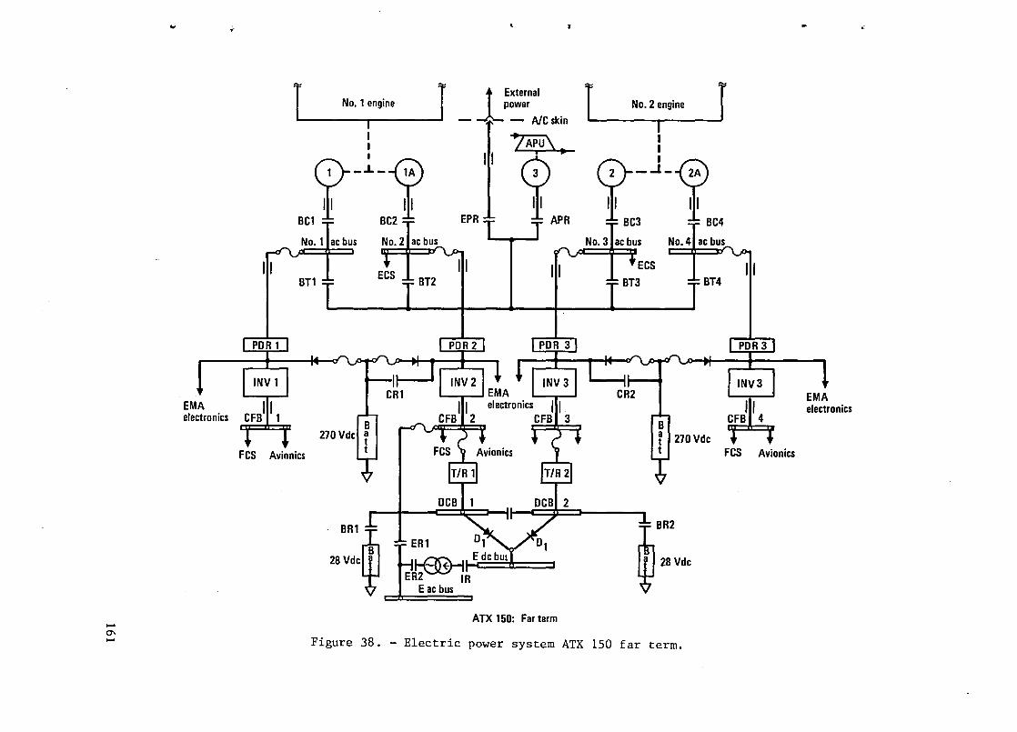
...... 0\ ......
.,;
EMA electronics
or ~
~ r r -External 1 No.1 engine Ipower . No.2 engine J I - - AlCskm I : LAPU\ I
0-':'-B II;· 0-1 -0) ~ ~ft ~ II 1 n, 1.
BCl BC2 BC3 BC4
:0. I' b,,' No.2" b" No.3" b" No. J" b"
III II ECS 1 III BTl -r- __ BT3 __ BT4
FCS Avionics
B 270 Vdcl ~
t
BRIm
28Vd'~ ___ _
ATX 150: Far term
~BR2
W 28Vdc
Figure 38. - Electric power system ATX 150 far term .
FCS Avionics
EMA electronics

Constant power is furnished on a dedicated (customized) basis utilizing four PDRs and four static inverters. The PDRs provide a constant level of 270 Vdc power over an approximate 2:1 speed range of the engines and are used to supply the power electronics for the electromechanical actuators, and the four static power inverters. These latter units provide three-phase 200 V Hz constant frequency power for the avionic system and the four FCS computers. Other dedicated power is delivered to the 28 Vdc system by two unregulated 28 V 120 A T/R units, which are connected to the two normally isolated ac busses, DCB1 and DCB2: dc batteries at 270 V and 28 V are used as emergency back-up to the PDR and T/R units.
Bus ties BTl through BT2 are used to enable any generator to feed any bus, and the bus tie system itself is connected to the APU generator or to external power via three-phase relays (contactors) via the APR and EPR contacts respectively. Phase sequence, voltage, and frequency logic (derived from an external power monitor, EPM) control the closure of the EPR contacts to ensure that only power of the proper type and quality can be applied to the airplane.
7.4.2.2 ATX-150 far-term power distribution: In common with the ATX-350 and -700 near-term airplanes, a distributed power bus system is proposed for the three-phase 400 Vac and the 270 Vdc power system. Figure 38 is not rigorously correct to the extent that there is no tie bus per se; rather, the figure is schematically representative of the fact that all busses can be supplied" from any single power source that may be operating. It is implicit in this that while many different bus sections may be closed (tied together) they will do so only under control of a strict and reliable automatic interlock system. It in further implicit that as the 30phistication (and complexity) of these bus systems increase, the whole power system management must come under the purview of automatic digital logic control.
Specifically, the -150 will follow the same redundancy criteria set up for the -350 airplane e.g., triple-distributed bus system in each wing, quaddistributed bus system in the fuselage and empennage. Figure 39 is an electrical schematic of the distributed ac bus system for high voltage/high frequency power. The nomenclature is basically as before, in that bus contactors BCl through BC4 control the connection of the engine power generators to their respective busses, while the bus ties BTl through BT4 are used to close appropriate bus sections when engines and/or generators fail. Additional power sources on the distributed bus systems are the external power and APU systems. Again, EPR controls the connection of external power and APR the connection of the auxiliary power unit power supply. When generators are OFF, and either the APU or external power are ON, BTl through BT4 will be closed along with the EPR and APR contacts.
Figure 40 is a similar schematic showing the configuration of the distributed bus system required for the 270 Vdc system. No detailed description of this is required, since it follows the configuration of the three-phase 400 V 800 Hz system. The system also appears simpler than the ac distributed bus system and this is mainly because of the absence of the bus tie contactors
162
~
,T
...
•
t.

-0\ W
... ., • ..
~ External [ $ l power
I I r7Ll J....J::'\
I EP' ACBll ~rf·2 T ACB3
[
BTl BT2
BT3 I BT4
ijlAP'
p--~--0 ATX 150: Far term
Figure 39. - Ac power distribution, ATX-ISO far term.

ACB 1 ACB 2 ACB3 ACB4·
~ ~ ~ J
II II II II I PDR 1 I 1 PDR 21 r PDR 31 r PDR 41
• • - ... ·L ... .- •• I • - . . • .... I r
CRl ... I 1\.fb---. CR2 - - I ,~ --Batt Batt
\ t7 \ t7 ,
ATX 150: Far term
Figure 40. - 270 Vdc power distribution, ATX-lSO, far term.

..
,-
....
f'
"
,.-,
on the ac side of the PDRs. It is however evident that the four PDRs can be powered from any single power source, on the ac side, so bus ties are not necessary on the dc side. As a result there is no problem of automatic logic and interlock controls in the 270 Vdc system.
7.4.2.3 ATX-lSO far-term emergency power: Again because of the similarity with the ATX-3S0 far-term systen, no detailed description is necessary for this system.
Figures· 39 and 40 jointly depict the configuration of the emergency power system in the -ISO far-term airplane. The triple/quad redundancy in the high voltage ac and high voltage dc power systems again permit any power source to supply any bus section.
In the event of any generator/engine/PDR failure, appropriate action is taken by the power management system; this functions cooperatively with the automatic load management system (ALMS). Therefore, if compound or mUltiple failures are present the ALMS operates to shed loads in accordance with a prioritized load schedule. In the event of an all-engine out condition, the APU will be started and the APU generator will furnish power to the primary ac busses (ACBl through ACB4) and the four PDRs. All busses and power sources such as the inverters are therefore energized and any load can be powered. However, to avoid overloading of the APU generator the ALMS will disconnect all but the flight critical loads and any other loads essential for safe flight operation. During the short delay time before the APU comes on line, the two 270 Vdc batteries (see figure 40) will power the flight control system.
The 28 Vdc system, as shown in figure 38, comprises two normal dc busses (DCBl and DCB2) and each of these is backed up by a 22Ah 28 Vdc battery. For essential and emergency dc loads an emergency dc bus, EDCB, is provided, which is tied via isolation diodes to the DCBl and DCB2 busses. Power to the EDCB can therefore be derived from anyone or more of four dc sources; the two 28 V batteries and the two T/R (transformer-rectifier) units.
Emergency ac power is furnished by a small rotary or static inverter of approximately 2S0 VA capacity operating from either of the two dc busses (DCBl or DCB2) and their back up batteries. Normally, the emergency ac bus, EACB, will be powered from the constant frequency bus, CFB2, via contacts ERI. This relay in effect is a no-volt relay, which is sensing power on CFB2; if power on CFB2 fails, then contacts ER2 and IR will close resulting in the start up of the emergency inverter (via inverter relay, IR) and the powering of EACB via contacts ER2. In addition to its emergency role, the emergency inverter can also be used to power engine instruments, fuel gages etc. during engine start up, before conventional ac power is available.
7.4.2.4 ATX-lSO far-term engine starting: In common with the ATX-350 far-term airplane. the SmCo engine power generators are used as synchronous motor starters for the two engines on the -ISO airplane. Figure 38 which depicts the completed power system for the ATX-lSO far-term airplane shows that
165

two starting inverters are provided for the purpose of generating synthesized rotating ac fields that are sequentially applied to the starter-generators. The rating of the inverters is based on the requirements of a 20,000 pound thrust engine of the E3 type. These power requirements for each inverter are presently estimated at approximately 100 to 125 kVA, with each one being thermally rated to start both engines in sequence, and on the assumption that there may be an abort start on one engine. As a result, either inverter must be capable of at least three starts and one engine purge start on a standard hot day.
Engine starts, upon initiation from the flight station, will be completely automatic and will be programmed to provide the necessary acceleration up to self supporting speed, or ground idle speed of the engine. Figure 30 is typical of the starting schematic and will be essentially similar for all engines. Control of the power contactors can permit the use of one or both generators to start each engine, but, whereas the use of one starter-generator will increase the dispatch reliability of the airplane, it will require an increase in the electromagnetic, and electrothermal, rating of the individual machines. This, along with an evaluation of different programmed start cycles, is in need of further study and evaluation. A part of this further study must also be dedicated to assessing the logistic support aspects of the all electric airplane (vis-a-vis the airport facilities, etc.) and evaluating alternative engine start power sources, such as three-phase 200 V 400 Hz, three-phase 400 V 800 Hz, and three-phase 200 V 60 Hz ac power.
7.4.2.5 ATX-150 far-term ECS: Ar. all-electric ECS of similar design to that described for the -350 airplane is used to furnish the heatinf., cooling, and pressurization needs of the -150 far-term airplane.
In the interests of fuel conservation, a 50 percent recirculation system is proposed in which the electric motor power compressors provide 50 percent fresh air and 50 percent is recirculated from the cabin. The recirculated air passes through slots in the ceiling after which it is passed through filters. to the recirculation fans. The advantages of the air circulation is that in an engine bleed type ECS, it minimizes the engine-bleed requirement by 50 percent and, in the case of the all electric ECS, decreases the horsepower rating (capacity) of the ECS compressor motors by 50 percent. The disadvantages of the recirculation system is an increase in hardware weight, installation complexity and, additional maintenance support costs viz: changing filters etc.
The -150 is configured as a two pack system, with either pack having the capability to supply the total ECS requirements of the airplane if one pack fails. However, because of the possibility of a further ECS pack loss, the flight will be continued at a lower altitude, in accordance with FAA requirements.
Figure 38 is illustrative of the ECS design that will be carried through into the -150 airplane. Pressurization of the fuselage is accomplished on the same schedule: 6000 feet cabin up to 35,000 feet altitude, and 8000 feet up to 39,000 feet (an approximate 8.33 psi cabin differential pressure). For the maximum ceiling and the rated fresh air flow requirements, each cabin
166
,~
J
A"
<'

'~
"
', ..
r'
:'"
compressor motor is rated for approximately 55 hp under normal two pack operation. Under one pack operation the inlet guide vanes will be modulated to decrease air mass flow and the airplane will descend to a lower altitude. Heating of cabin-inflow air is normally by means of the heat of compression incident upon operation of the compressors, but duct electric heaters are also used to provide heating when the compressors are not running. To accommodate the atmospheric conditions of the complete flight envelope the cabin compressor motors are two speed, effected by pole changing. This permits operation of the compressors at low speed, during low altitude operation when the air density and atmospheric pressures are high and high speed operation at the high altitudes, when the air density and atmospheric pressures are low. The inlet guide vanes are also modulated at the different motor speeds to cover the different pressure ratio/flow requirements as a function of altitude.
Cooling of the cabin in the -150 airplane is effected with two hermetically sealed freon vapor cycle units, which are powered from the three-phase 400 V 800 Hz system. Like the cabin compressor, rGVs will be used on the freon compressors and the drive motor will also be a pole changing type to provide dualspeed operation. Unlike the cabin compressor, the rated (design) output of the vapor cycle system will be maximum during hot day ground operation with a fully loaded airplane. The displacement of the freon compressor will therefore be designed to meet full capacity cooling, whether it is supplied with 400 Hz or 800 Hz power. The total sensible and latent heating load for the 150 PAX airplane is estimated at 130,000 Btu/h, requiring approximately 11 tons of cooling during hot day, 104°F, ground operation, with a full passenger complement.
7.4.3 ATX-700 far-term secondary power system. - The far-term secondary power system for the 700 airplane, (as in the other far-term airplanes) is an all-electric secondary power system, in which engine bleed, pneumatics (for thrust reversing, air turbine motors, etC.), and hydraulics are all eliminated. This airplane, like the others, will tterefore be identified by a signific£nt reduction in the normal complexity of conventional secondary power systems which will be manifest by major simplication of the engine and by a major reduction in engineering design time, system test time and aircraft producticn time. The additional benefits of the all electric airplane will derive frem the improvements incident upon the different operational and logistic support aspects of these large airplanes.
The electrical s1z1ng of the SmCo generators will again be dictated to a large degree by the starting requirements of the 50,000 pound thrust engines, but as pointed out in the previous NASA-JSC/Lockheed Study which identified the all electric airplane, there is a synergistic relationship between the capacity of the air-conditioning system (the ECS) and the horsepower capacity required for starting the engines. There will also be some fortuitous aspects inherent in the application of the starting inverters that may well find additional roles in these advanced technology transports. The all electric airplane is in the embryonic stage, and innovativeness will playa large part in the evolving development of the future energy efficient air transports.
167

The development of the engines, designed specifically for mechanical rather than bleed air power extraction, will themselves require significant study and evaluation to achieve cycle optimization and maximum fuel economy. Such studies must address the aero thermodynamic characteristics of the overall engine cycle and components in order to determine the operation line of the compressor, over the complete range of engine power settings and engine speeds. The engine's stability margins are impacted by the deletion of interstage and last stage compressor bleeds and by larger demands for shaft power. These considerations must all be directed to the achievement of acceptable stability margins, during engine accelerations, transient altitude changes and bursts and chops in power settings etc. A detailed mission analysis must also be a concomitant part of the continuing studies of the engine performance and it must be evaluated over the complete range of the altitude/speed flight envelope. In reality, the"change in the design reconfiguration of the engines will motivate the suppliers to rethink the engine cycle and to consider changes in the physical design aspects of the engine; variable geometry stages, compressor/ turbine redesign are other design options.
An important related aspect will be the design/installation considerations of alternative drive configurations. The objective, to reduce engine inlet profile drag, dictates smooth aerodynamic contours and the avoidance of protruding fan-case mounted accessories. Figure 41 illustrates candidate mounting methods, the conventional chin mounted accessories illustrate the problem while the pylon and integral mountings are more near'ly optimum. The reduction of the number of accessories, as implicit in the all electric airplane, itself permits the use of a fan-case mounted "austere" gearbox, that could result in a low aerodynamic drag-count power plant, but core mounted accessories could also be considered. This latter approach achieves the necessary low inlet drag profile but places the secondary power system components in a less accessible position for maintenance.
The engine manufacturer's dependence on engine driven fuel and lube pumps requires additional pad faces on the accessory gearbox modules, but this problem could be eliminated by the use of electric drives. With the Lockheedproposed plan to use a minimum of two generators per power plant, electric driven fuel/lubrication pumps could be used to major advantage compared to engine driven pumps. Electric drives would permit the use of centrifugal pumps and an ability to control flow rates independently of engine speeds. In this way mismatch of flow versus demand could be avoided and unacceptable temperature rises in the fuel could be avoided during idle descent when there are low fuel flows. These again are the additional salutary effects of an all electric airplane.
Finally, in the considerations of alternative drive approaches for the starter-generators there is the choice of mounting the permanent magnet rotors directly over the high pressure spool shaft. This has the major advantage that it completely eliminates the need and weight of the accessory gearbox module - if, the engine manufacturers accept the philosophy of electric fuel and lube pump drives. This solution for aircraft power generation is particularly appropriate, when constant speed drives are eliminated since the
168
,A
1;
.~

lVI:lf>3J.NI
C ':II .. I I
!I: I,'
I I
N01Ad 03J.NnOIJ\l NIHO
"'-

generator can live with the variable speed range of the engines. The basic simplicity of mounting the permanent magnet rotor over the high pressure spool shaft is, however, somewhat abrogated by the incorporation of complex mechanical disconnect clutches, so this problem must be attacked on the basis that such clutches must be made elegantly simple and reliable. Figure 41 shows a generator mounted integrally in a high bypass turbofan engine.
There are also some other disadvantages to the lEGIS (integrated engine generator/starter) philosophy, not the least of which would be the higher temperature environment for the generator and the fact that burying the generator inside the engine poses a maintenance and support problem for the airline operator. Because of the maintenance aspects, the starter-generator must have a reliability higher than conventional rotating machinery if aircraft delays 'due to generator failure are to be avoided. Further, it is pertinent that as the generator is a starter also, a one-generator-out dispatch-capability cannot be awarded the airplane, unless the philosophy of two generators per power plant is used across-the-board, and one generator is capable of the engine start.
The maintenance access problem of lEGIS installation is not itself untenable, because once the engine manufacturer accepts the generator as an integral part of his engine, he will become much more involved with its mechanical and electrical design aspects. He will also re-evaluate the construction details of the engine and move more towards modularity wherein the bypass fan, for example, may be made readily removable. His contributions to the mechanical design aspects, and his responsibility for mounting the generator within the engine, will be factors that will prospectively enhance the reliability aspects of the starter-generator.
Overall, therefore, from a mechanical standpoint, the lEGIS installation is not wholly impractical, but there may be electrical shortcomings that also tend to inhibit a complete endorsement of the concept. One of the electrical considerations is that the generator designer no longer has control over his generator speed and he must live with the speed and speed range of the high pressure spool. This has two potential shortcomings; the use of very high speed generators might not be possible (for the purpose of reducing size and weight) and, it is not possible to reduce the polar-moment of the high pressure rotor relative to the generator. If a step down ratio can be interposed between the engine and the generator, then the referred inertia can be reduced by the inverse square of the reduction ratio; also, the acceleration torque requirement can be reduced. These therefore are the design trades that must be pursued to evaluate further the efficacy of the lEGIS, as a viable and practical installation.
7.4.3.1 ATX-700 far-term electric power system: The preceding paragraphs highlighted some of the generator-engine interface aspects (that are pertinent also to the 150 and 350 airplanes) but it is evident that even in a four-engine airplane, such as the ATX-700, there is merit in considering a minimum of two generators per power plant. This is particularly true if there is a consensus from the NASA, airline operators, and the engine/airframe suppliers that a
170
,I
...
'"

..
,.
..
I'
~
one-generator-out dispatcQ reliability is desirable and required. As stated, a legacy of the decision is that there may be a slight oversizing penalty on the generator, vis-a-vis the fact that the aircraft loads may permit a lower machine sizing. However, this may be an acceptable trade and it may be that a generator to starter mismatch does not always exist; the ideal condition is that the aircraft loads dictate a machine-size, that is comparable to the engine start requirement.
The first design premise for the ATX-700, therefore, is that there are two generators/power plant. It is also possible, though not mentioned in paragraph 7.3.3, that single generator starts could be accomplished by the utilization of an additional (maybe 2:1) step-down gear ratio that would be effective during the engine start mode, but which would be bypassed in the generator mode without the need for running-gears. These and other details should be considered in any ensuing NASA program, relative to the all electric airplane.
Figure 42 is a schematic of the proposed electric system for the ATX-700, far-term airplane. The primary ac power generation in the airplane is furnished by eight 200 kVA three-phase 400 V 800 Hz generators (two/engine) that provide quadruple-redundant power distribution in the empennage and fuselage and triple redundancy in each wing. To this extent the distribution system follows the philosophy of the two and three-engine airplanes, although it would be extremely simple in the four-engine airplane to furnish quadredundancy in each wing also. A specific description relative to figure 42 is not necessary since the commitment to FBW and PBW flight control system in all the far-term airplanes demands the same high level of redundancy in the power supplies and the power distribution, regardless of the number of engines.
One APU is still shown in the ATX-700 airplane, although this airplane, more than all others, might merit the use of two APUs. Two APUs would offer the airplane significantly improved emergency power back up capability and it would have favorable trades relative to ground taxiing, engine starting, and ground logistic support. As with the other all electric airplanes, the multiple power sources must be carefully interlocked, via the digitally controlled power management system, to ensure proper operation of the whole system during ground and flight operation. There can be no inadvertent paralleling of the engine driven generators EDGs, nor any paralleling between the EDGs, the inverters, the APU generator and external power. The system must also provide that during sequential start operation of the engines other alternative power sources can be tied to the other bus sections to supply the customized, dedicated power required. Not all of the power contactors and protection are shown in the schematic since the power generation system and the power distribution system are in need of more detailed study and evaluation. It is also of note that the switching logic and interlock controls are not detailed since this also is a subject for more detailed consideration.
7.4.3.2 ATX-700 far-term engine starting: The engines in the ATX-700 far term are in the same thrust class as the -350 far term, so the enginestart power requirements are the same, but the requirement for four engine
171

External ~ Engine 1 r; Engine Q power ~ r;==Engine 3 ~
lA 2 2A 5 3 4 4A
I I I I.
,ACBl ~ t--c::;jb-~:::;:::b-II-c=-=:p... .... II .11
BRl BR2
0 1 02
HV DCB1 HV DCB 2 HV DCB 3 HV DCB 4
Batt 270 V 270 V Batt
I I CFB 1 CFB 2 CFB 3 CFB 4
03 I I 04
MDCB2
28V
Batt BR3
EA~C
II BACB
o-C:===::!:===::::J EDCB
SRl
No. 1 4--I1-.... I~ 28V batt ~ I _ No., 28V Emerg de bus
Batt
Emerg ae bus APU start bus
Figure 42. - Electrical power system ATX-700, far term.
, • .. .'\,

•
•
..
t'
~
~
starts places an additional electrothermal burden on the starting inverters; because of this, it is apparent that a dynamic cooling-loop will be necessary for the inverters. It is similarly projected that dynamic cooling of the starter-generators will also be required .
It is in further consonance with the synergistic benefits of the all electric airplane that the full commitment by the engine suppliers to electrically driven fuel pumps and lube pumps will permit a practical and realistic integration of the engine pump systems with the dynamic cooling loops required for static power supplies and the rotating machinery. These and the other application aspects of integrated cooling system are the additional study items to be identified as part of the future NASA programs.
7.4.3.3 ATX-700 far-term emergency electric power: The philosophy of the different emergency power systems in the ATX-700 far term is guided primarily by the all electric FCS: as a consequence significant attention is paid to the PDRs, the back-up/redundancy aspects of the 270 Vdc power system, and the quad-redundancy of the static inverters that power the onboard digital flight control computers and avionics.
As shown in the figure 42 schematic, the four PDRs are tied to separate generators and bus sections. In addition, the two 270 Vdc batteries provide further back up capability in supplying dc power to the inverters; this ensures a noninterrupt power capability in the unlikely event of an all-engine-out condition. In most all other cases, the power busses and bus sections can be tied together under the control of the power management system. In the case of the constant-frequency busses, (CFBs) however, they are not tied (or paralleled) since the design criteria are that there shall be four separate/isolated sources, and that they shall be so installed and routed that there is no possibility of cascade type failures, as is sometimes possible with other bus and load transfer systems.
7.4.3.4 ATX-700 far-term low voltage dc system: The low voltage 28 dc power system follows the basic design philosophy of the previously described systems except that there are three transformer-rectifier, (T/R) units, instead of two. Again, these T/R units could be replaced by high frequency switching converters, subject to the acquisition costs, reliability, weight, and maintainability aspects of these devices being acceptable. The emergency dc buses, EMDC 1 and EMDC 2 can be powered from all or either of the three T/R units, and by the two 28 Vdc batteries: the two EMDCs are normally tied through the normally closed bus tie, BT8. Similarly the two 28 Vdc batteries are tied with the dc system through the normally closed battery relays BR1 and BR2. The low voltage dc system, as before, powers the emergency inverter system that might furnish emergency 400 Hz ac power before other power sources come on line.
7.4.3.5 ATX-700 far-term ECS: The final decision on the configuration of the ECS system for the ATX-700 far term has not been made and is open for further evaluation but, for this Benefits Study, the typical three pack configuration has been selected for the purpose of the tradeoffs. In further
173

studies of all electric ECS configurations, serious consideration should, however, be given to a four-pack system in the interests of more flexible operational possibilities and reducing the horsepower level of the individual ECS packs. In this latter regard, it is pertinent that as the same kVA capacity generators are used on the ATX-700, as on the ATX-350, the ratio of the generator capacity to the largest motor load is important. The electrical schematic of the ECS, for the far-term ATX-700, is similar to the far term -350 on an individual pack basis.
Based on the typical 50% air recirculation system as for the other far term aircraft, the fresh air mass flow will be 420 ppm. Since the same cabin pressure profile will be maintained (6000 feet up to 35,000 feet and 8000 feet at 42,000 feet), the motor horsepower is sized by the requirement for an approximate 3.4:1 pressure ratio. Using a three pack system, the individual fresh air flow/pack would be 2.3 pps approximately; this would correspond to a compressor shaft rating of 175 hp, which is high relative to a 200 kVA individual generator capacity. Therefore, a change to a four pack system would reduce the individual pack rating to 130 hp and this would be more compatible with the 200 kVA generator rating.
The cooling load is also significant on the ATX-700 due to solar heating, the sensible heat load, and the latent heat load. The latent heat load itself is estimated at 136,000 Btu/h and when this is added to the sensible heat load, the total cooling requirement for the ATX-700 on the ground/standard hot-day is estimated at 560,000 Btu/h; this corresponds to a 50 ton plus cooling capacity and 16.6 tons per pack (three pack system), or 12.5 tons per pack for the four pack system. Based on a major reduction in the sensible heat load under the 35,000 feet cruise condition, the cooling requirement of 560,000 Btu/h is estimated to drop to some 230,000 Btu/h with a fully loaded cabin.
Heating loads are small in relation to the cooling loads and are dictated primarily by low temperature ground night conditions during winter operation. As with the ATX-350 far-term airplane, heating of the cabin is by means of heat of compression, but electric duct heaters, with modulated SCR control is provided when the motor driven compressors are not running.
7.5 Advanced Avionic Components
In considering the avionic components configuration it should be noted that all the other configurations for evaluation also use advanced avionics components. In fact, the other configurations are made possible by advanced avionics. The flight controls require advanced computer and software architecture. Advanced large scale integrated circuits are assumed in order to attain the weight reductions. Similarly advanced secondary power, the advanced cockpit, and the onboard air traffic control avionics require advanced digital technology. However, there are some subsystems not included in the other configurations. This configuration, Advanced Avionic Components, sometimes referred to as "components" for brevity, includes the following:
174
,.
•
.. '
"'"
,.

"
-.
~
..
~
• Digital data handling
• Large scale integrated circuits
• Standard module (card)
• Integrated avionic rack
• Multiplexing, two way, multiple access
• Advanced sensors: Laser gyro, laser air data.
This configuration includes digital data handling, LSI, and multiplexing only for navigation and communications because these technologies were included in other configurations for the other subsystems. The standard module and integrated avionics rack was not included in other configurations because these are radical and unusual technologies which might be controversial and contaminate the results of the evaluation of other configurations.
Digital data handling and MUX involve built-in MUX interface in all major equipment. Remote devices with signals such as feedback from actuators and control and with low-bandwidth information from sensors will have either builtin MUX interface or may have an adjacent MUX station, depending on the number of signals involved and the adaptability to standard MUX-DEMUX units. MUX is quadruple redundant with built-in test, end-to-end checks in operation, and majority voting. Fiber optics is not used because there is no weight saving for these configurations, there is probably increased maintenance and EMI requirements can be met by conventional methods. The bus is operated at 1 Mbps and twisted pair are used, shielded only in certain vulnerable areas.
The laser gyro is similar to production equipment but is assumed to be second generation and thus reduced in weight. Fiber optic multiturn paths were not assumed in the gyros.
The laser air data system is now under development at Lockheed and shows promise of increased accuracy and reduced weight.
The integrated rack and standard module are technology being developed by the Naval Avionics Center in Indianapolis and Crane. This program started as the Standard Hardware Program, approximately 1967, and was envisioned as a set of plug-in modules with standardized functions and interface so that equipment could be built up from modules thus saving money in design, procurement, parts stocking, and maintenance. This program has been moderately successful in the Navy with hundreds of module types in operation, and has developed the standard electronic module (SEM) and improved standard electronic module (ISEM). The Navy ISEM is approximately 50 mm x 150 mm (2 in. x 6 in.). Figure 43 shows an integrated rack with standard modules (cards); the modules are inserted from the front and clamped by the edges in a cold plate. The plate is refrigerated with freon and maintains a maximum case temperature of
175

30 IN.
-----24IN.----- --10IN.--
II' 1 1 "
I rr :t
~ 15-
~ II 15 1-!---
~ POWER SUPPLIES
~~ COLD PLATE
CA 6 REQUIRED
RDS 0.. CARDS 0.. CARDS 0..
I I II, ,II -, II
9 REQUIRED
f-- ------ -II' " I II'
15 I
V) ~ 15
~ II CARDS I ~
0.. II CARDS I 0..
- ---------IT I II 15
1 CJ? 15
~ 0.. I, CARDS II
V)
0.. II CARDS ~
L ___ -'
~~\ , ... : r- -:, I
- "./4/1' I 1 i, ,- 11.._..1: @; ~"\\ 11 II ,r ~ CONNECTOR
PANEL
LJ lJ u w
FRONT ACCESS -........
FILTER
...... __ ...1 BACK PLANE WIRING
~-......
CARDS
CARDS
t1 HI SPEED CENTRIFUGAL
60CFM I
f---- I BLOWER, ELECTRIC
__ ~~~~I_~I_CONNECTORPANEL
, DEHUMI 01 FY EVAP
WATER DRAIN
Figure 43. - Integrated avionics rack .
...

:>
~
,.
...
60°C for the semiconductor~; this low temperature leads to MTBF's 5 to 10 times that of today's avionics. Only a small amount of air is circulated and no outside air is introduced; this reduces or eliminates buildup of dirt on the avionics components.
The standard module and integrated rack are programs which the military is pursuing; they mayor may not be adopted by the commercial world when proven by the military. The benefits are there if one can overcome the inertia and natural reluctance of manufacturers to standardize to the extent that competitors could build replacement parts.
The foregoing discussion applies to all three aircraft; the benefits, shown in Section 9, vary with aircraft because of different proportions of fuel, depreciation, maintenance and crew costs.
7.6 Advanced Cockpit
The major features of the advanced cockpit configuration are:
• Displays are flat panel, multipurpose, color
• Multifunction controls
• Side-arm controller
• Three-man crew for ATX-350 and -700
The flat panel displays are either LCD or electroluminescent; at this time it . is not clear which of these two will be most advantageous. The displays will be arranged as shown in figure 44 which is from Lockheed-Georgia Company contracts with NASA LaRC. The normal arrangement is with the vertical situation display (VSD) in front of each pilot. The horizontal situation display is inboard from the VSD and the map display is in the center. Engine and system displays are in front of each pilot on the sloping panel. Of course each display is capable of displaying all formats; for example the engine and system formats would be on the HSD during startup.
The keyboards are integrated with the display, that is the display above the keyboard names the function of each key, furnishes information for the decision to be made, and guides the pilot where necessary.
Advanced alerting and warning systems are provided utilizing synthesized voice, tones, and flashing explanations on the multipurpose displays. Warnings requiring a quick response have a horn signal with a voice command following such as "pull up." Warnings which require immediate consideration have a clacker warning followed by a voice warning and a central visual display which automatically presents the pertinent data required for the command decision. Alerts which caution but do not require immediate action have a bell
177

Figure 44. - Advanced cockpit.

•
;,
'""
'"
..
...
signal, no voice command, and a presentation of the problem on the visual display. Advisories such as crew call have a chime tone with an explanation on the visual display.
A HUD is provided for each pilot. It has a 30° field of view and is capable of presenting a variety of data from the VSD and HSD displays according to the mode selected. One mode is backup to the Autoland system. The HUD utilizes a holographic generated lens.
A limited number of functions are controlled by the pilots voice, those functions which increase workload during critical flight conditions but are not critical by themselves; examples would be flaps, landing gear, thrust reverse, and ground spoilers.
A three-man crew was assumed on the two larger aircraft although now it seems that some of the political reasons for the third man in the cockpit has disappeared. A flight engineers panel has been provided but is probably not needed from a technical standpoint.
The monetary savings due to the advanced cockpit are small compared to some other technologies. However, there are small savings in weight and cost, and large savings when the technology is considered as enabling the two man crew and the air traffic control configuration.
The foregoing discussion applies to all three aircraft. The benefits, shown in Section 9, vary with aircraft because of the three versus two man crew and the associated different proportion of fuel, depreciation, maintenance, and crew costs.
7.7 Air Traffic Control (ATC)
It was thought that some large reductions in operating cost could be made in the area of ATC; figure 45 puts this in perspective. Taxi out time could be reduced by scheduling the various aircraft in proper order for takeoff and delaying start of taxi until required. Area navigation (R NAV) would allow direct flight rather than from way point to way point. Holding patterns and the STAR geometry could be eliminated by proper scheduling and use of 4-D navigation with the microwave landing system (MLS); the onboard 4-D system combined with the MLS can bring the aircraft to the final approach about 4 km (2 n.mi.) from the runway so precisely that adjacent aircraft do not interfere with each other.
The implementation of these functions is in the Flight Management System. The flight management system capabilities are in three categories:
• Performance management for fuel/cost conservation, included in the baseline configuration
179

TAXI OUT
STAR GEOMETRY--i:r---' , MLS/-......... ~~
."."" .".""
."."" ."."" " "
.". RNAV~.".."..".
, \ RUNWAY
,,','~ ___ -------, HOLDING
" '" WAY POINTS , , , "-
" DEPARTURE
RUNWAY
Figure 45. - Unconstrained flight path.

,~
)
''Ie
..
..
" ..
• Navigation and guidance
• Assistance in the cockpit management task such as programming of communications, radio aids to navigation, and engine and fuel management.
The navigation capability of the FMS is obtained by integrating the inertial systems, VOR, DME, MLS, Omega and GPS. In the terminal area. the VOR, GPS, and" DME are the more accurate and when available are used to update, calibrate, and adjust the inertial. The FMS contains the logic to compare and select the outputs of the navigation subsystems for the most reliable and most accurate overall result. The navigation calculations are input to the perforperformance management functions, and, based upon the waypoints and desired arrival times at the waypoints, the FMS calculates and guides the aircraft in the optimum path in space and time. The present location and predicted path are available for display.
The pilot assistance (cockpit management) capabilities of the FMS include preprogrammed acquisition of the" enroute VOR, DME, and communications facilities, and monitoring of the engines and fuel. The engines are monitored for out-of-tolerance temperature, pressure ratios, and fuel flow. The fuel is monitored and transferred for c.g. control. Aircraft weight and c.g. is continuously calculated starting with aircraft weight at takeoff obtained from load sensors in the landing gear.
The FMS has two separate computers each of which performs all computations in parallel and compares the results. Each computer performs independent self-check at two cycles per second. Results of the comparison and self-check are presented to the pilot for selection of the controlling system.
It is recognized that the implementation of this technology depends upon the FAA ATC implementation of flight planning and en route and terminal area metering and spacing. The cost of the ground effort is not included in this evaluation. However, the benefits to the ground FAA ATC are positive in that the system can handle more traffic by providing closer and more even spacing. These benefits have not been included in the evaluation either. Thus neither the cost nor the benefits to the FAA ATC system are included.
The systems included in the airplane are microwave landing system (MLS), 4D-navigation, cockpit display of traffic information (CDTI) and discrete address beacon system (DABS). The ground system must include the ground counterpart of MLS and DABS and in addition provide other services such as automatic en route aids (AERA), electronic tabular system (ETABS) and conflict resolution. The aircraft system is rather simple electronics, although possibly too expensive for many general aviation aircraft. The ground based system would require new computers and software which are scheduled within the time frame of interest. To make it happen requires commitment on the part of the government; the airlines will certainly be willing to implement their part for the savings involved.
Aside from the calculable money aspects, other benefits include land use, energy saving and noise abatement. The increased traffic handling capability
181

can reduce the number of new airports required and the more precise approach reduces the low altitude power on portions of the approach considerably, reducing the noise impact on residents by a like amount.
Table XII shows estimates of the DOC saving for the various items discussed above. The complete configuration was evaluated by ASSET to give the bottom line number but the individual items were not evaluated by ASSET. Electric Wheels are not included in the basic evaluation because the mechanization was not well understood and it was felt that weight and cost could not be estimated to the level of confidence consistent with other inputs. Reduced fuel reserves were included in the basic evaluation on the basis that with Autoland the alternate airport need not be out of the weather area. The reserve distance was reduced to 91 km from 370 km (50 n.mi. vs 200 n.mi.) and the reserve for loiter was reduced to 25 minutes from 45 minutes.
The delays in minutes were obtained from observations and agree closely with many independent assessments of average delays; however, there is no recognized source for this kind of data; each organization reports delays on their their own basis. The published schedule has built in delays. Usually delays are reported as delays from scheduled time and many times a tolerance is used such as 15 minutes, i.e., there is no delay unless the aircraft is 15 minutes behind schedule.
The foregoing discussion applies to all three aircraft. The benefits, shown in Section 9, vary with aircraft because of differences in stage length and the associated different proportion of fuel, depreciation, maintenance, and crew costs.
TABLE XII. - DELAY REDUCTION, SAVINGS POTENTIAL
% of DOC
Delay Crew and Fuel and minutes aircraft weight Total
Taxi out 5 0.52 0.52
Electric wheels 1.30 1.30
SID geometry 0 0 0 0
RNAV 4 0.40 0.66 1.08
Loiter and hold 5 0.52 0.69 1.21
STAR geometry 5 0.52 0.69 1.21
Electric wheels in 0 0 0.65 0.65
Total 19 min 5.97%
Assumptions: Average U.S. delays, 2500 n.mi. cruise, wide body aircraft
182
~
~.
...
..

,.
•
8. ANALYSIS
Major inputs to the evaluation are weights, cost, and maintainability parameters. Following are explanations of the analytic methods used in deriving these input quantities from the conceptual designs developed in Section 7. In addition a separate analysis was performed to evaluate certain new technologies and possible sources of additional benefits.
8.1 Weights
The weight effect of each tradeoff was evaluated by comparing the new system, defined in Section 7, to a well defined baseline. Weights of new items such as actuators and electronic boxes came directly from vendors, together with wire counts and sizes that allowed calculation of associated wiring weight. Deleted equipment, plumbing, ducting, and wiring weights were based on details of contemporary aircraft scaled to the baseline configurations. Results of each weight comparison were input to the ASSET program to determine effects on overall aircraft sizing.
• The weight breakdown of the 350 passenger baseline was derived from
".
~
previous studies by adjusting the systems of interest to a scaled L-lOll. For example the control system weight was based on a detailed breakdown of the L-lOll with the individual items scaled to the ATX-350 configuration. Other advanced technologies such as composite structure, energy efficient engines, and supercritical wing had been incorporated into the baseline from previous study and were retained in the weight model. Lockheed, under lRAD programs, has maintained a set of advanced transport aircraft in the ASSET file for lRAD and airline customer studies. The 150 passenger aircraft in particular has been refined and exercised recently because of interest in Delta Airlines requirements. The ATX-150 thus came from airline studies. The ATX-700 has gone through preliminary design and was optimized with ASSET to furnish a baseline weight statement.
The ASSET program generates a group weight statement from a set of parametric equations. The entire aircraft, including engines, is scaled by the program. Thus, a weight reduction in an aircraft system results in the aircraft structure, power plants, and mission fuel being reduced as well. Each system configuration was designed and weighed without these scaling effects and the aircraft then rescaled by ASSET.
Table XIII shows the weight of selected systems for the three aircraft, for the eight configurations of each aircraft. The small differences in weight between configurations utilizing the same systems is caused by change in aircraft size. For example, the same anti-ice system is used for all configurations except NTSP and FTSP yet the weights vary from 469 pounds to 475 pounds because of the size variation of the aircraft. The anti-ice system is sensitive to aircraft size.
183

TABLE XIII. - SYSTEM WEIGHTS
WEIGHTS IN POUNDS
ATX·700 REF NTFC FTFC NTSP FTSP CaMP. COCKPIT ATC ALL
FI ight Controls 9100 7518 6647 8934 9747 9099 9050 8837 7050 APU 1202 1202 1202 1000 1000 1202 1202 1202 1000 I nstru ments 1426 1446 1444 1420 1417 1426 546 1417 563 Hyd. & Pneumatics 4384 4358 4334 4308 0 4384 4365 4263 0 Electrical 9804 9799 9794 9996 9936 9804 9775 9779 9873 Avionics 3284 3284 3284 3413 3413 3097 3839 3502 4059 Air Conditioning 11344 11344 11344 7186 7186 11489 11266 11344 7228 Anti Ice 475 474 473 145 144 475 475 469 143
ATX·350
Flight Controls 5396 4752 3913 5300 5816 5392 5369 5249 4202 APU 1202 1202 1202 1000 1000 1202 1202 1202 1000 I nstru ments 1054 1073 1071 1051 1049 1054 420 1049 437 Hyd. & Pneumatics 2259 2241 2221 2220 0 2258 2252 2199 0 Electrical 5737 5732 5726 5829 5793 5737 5724 5720 5754 Avionics 3075 3075 3075 3204 3204 2792 3622 3293 3745 Air Conditioning 6302 6302 6302 3982 3982 6373 6263 6302 4014 Anti Ice 382 381 379 116 116 382 382 377 115
ATX·150
Flight Controls 1798 2234 1824 1778 1767 1793 1666 1749 1702 APU 200 200 200 300 300 200 200 200 300 I nstru ments 702 702 702 701 700 702 240 699 239 Hyd. & Pneumatics 628 629 627 564 0 627 620 617 0 Electrical 1553 1553 1552 1657 1656 1552 1539 1549 1638 Avionics 1072 1072 1072 1072 1072 822 1250 1298 1226 Air Conditioning 2008 2008 2008 1206 1206 2008 1969 2008 1167 Anti Ice 203 203 202 105 105 203 202 200 106

•
~
"',
•
,~
The flight controls decrease in weight for advanced flight controls (NTFC and FTFC) but goes up for FTSP because of the change to electric actuators; but note that the hydraulic weight goes to zero in this configuration.
The instrument weight drops but avionics goes up in the cockpit configuration. This is because instruments were removed and replaced by cathode ray tubes (CRT) which are classified as avionics rather than instruments. For a similar reason electrical weight goes up but air conditioning weight and anti-ice weight goes down for the NTSP and FTSP configurations. The APU for the all electric airplane increases in weight for the ATX-150 but decreases for the other two. This is because engine starting sizes the APU on the two engine airplane but air conditioning sizes it on the larger aircraft.
Weight comparisons are shown in more depth in the Results, Section 9.
8.2 Cost
The major purpose of the cost analysis was to obtain direct operating cost (DOC) for comparison of the benefits of the various technologies. There could be other basis for comparison: weight, fuel, production cost, life cycle cost, return on investment and others; however DOC was selected for this study as being the most direct indication and/or the best understood within the , industry. To obtain DOC a complete cost analysis was required for input to ASSET.
The first step in the process is to delineate the changes from the baseline to the various configurations. The equipment changes are described in Section 7. The weights associated with these changes are noted in Section 8.1. These changes provide the inputs required to evaluate the configurations in terms of cost deltas. Certain equipment such as avionics boxes, ECS packages, and actuators are from manufacturers cost estimates, others such as w1r1ng, piping, and rigging base cost on weight. The configuration changes impact the following elements of cost and economics of operation.
• Avionics development
• Engineering development to incorporate changes
• Development test
• Systems production
• Avionics production
• Maintenance
• Return on investment (ROI)
185
• Cash flow
• Operating cost (IOC and DOC)
Each of the above elements of cost and economic indicators are evaluated for each configuration, utilizing ASSET.
The development and production costs for incorporating the advanced systems into the aircraft are determined through an examination of Lockheed experience on similar systems. The estimates for development and production cost for the avionics, electrical, ECS, and flight control equipment come from equipment manufacturers.
The ASSET program evaluates the configuration in terms of development, production, operations, and return on investment. The evaluation is dependent upon the costs inputs and also upon variation in the system weights. The ASSET program applies the cost inputs and places them in the proper category and also resizes the aircraft to fly the same mission at the reduced weight due to the substitution of the various equipment. The resizing of the aircraft also affects the total cost of the system, so that the final cost reflects equipment change as well as change in aircraft size. Operational costs in the form of direct and indirect operating costs (DOC/IOC) are also affected by the change in equipment and aircraft size and cost. The DOC is sensitive to the aircraft characteristics and cost, whereas the IOC is system oriented and is sensitive primarily to the number of passengers and the amount of cargo transported during the year.
The maintenance cost is affected by the reslzlng of the aircraft and the differences in the reliabilities of the equipmenL being removed and added. The maintenance cost for the conventional aircraft is based on L-10ll actual experience. addition of maintenance
The change to the maintenance factors are calculated for the the equipment. The method for determining the difference in for the various configurations is presented in Section 8.3.
The derivation of the maintenance cost deltas is from the estimates of the mean-time-between-failures (MTBF) for the various components. The maintenance formulas (ATA method) in the ASSET program are modified to reflect the changes in maintenance cost. The change in maintenance cost due to the resizing is handled internally in the program. The return on investment (ROI) is calculated on the basis of the revenues, expense and investment cost for the aircraft. The direct operating cost (DOC) and investment costs are influenced by the equipment changes and cause a change in both the cash flow and ROI. The revenue is constant because the stage length, the fare level, and the load factor remains constant for all configurations.
All costs and outputs are based on 1980 dollars. Production quantities are 1000, 300, and 250 respectively for the ATX-150, 350, and 700. Fuel cost is $2.12 per gallon, the estimated cost of fuel at the midlife of the aircraft in 1980 dollars, an escalation of 3.5% per year to the year 2000. Aircraft life is 16 years; residual value at 16 years is 15% for the ATX-150
186
.. "
v
~-

,t
I
~
4
~
and 10% for the ATX-3S0 and 700. The maintenance labor rate is $12.69 per hour and the maintenance burden factor is 2.174 for the ATX-1S0 and 700, and 3.13 for the ATX-3S0; the higher burden for the ATX-3S0 is because it is an international model.
Table XIV shows cost of selected systems for the three aircraft for the eight configuration of each aircraft. The small differences in cost between configurations utilizing the same system is caused by weight changes which in turn is caused by aircraft size as noted in Section 8.1. Note that the advanced flight control configurations, NTFC and FTFC, reduced the flight control costs because of elimination of mechanical rigging. Instrument cost was reduced for the cockpit configuration but avionics went up because the flat panel displays are considered to be avionics rather than instruments. Air conditioning cost reduced for the NTSP and FTSP but the electrical system cost went up.
DOC cost savings are shown in more depth in the results, Section 9.
8.3 Reliability and Maintainability
Reliability for safety is a major concern when configuring advanced flight control systems. Reliability for safety was not analyzed in this study because the flight control systems are of the same type as investigated in previous studies including the previous study for the Johnson Space Center, contract NAS9-1S863. These studies show that it is feasible to design for 10-9 failure per hour although the methods for monitoring,checking,and software verification are not clear at this time.
Reliability/maintainability analysis was conducted to provide inputs into direct operating cost models used in the life cycle cost analysis. The starting point of the analysis was L-lOll labor expenditure data obtained from commercial operations. The experience data were modified to reflect the configurations under consideration. Table XV shows the increments to the baseline maintenance labor and material; this is in man-hours per cycle (takeoff and land), man-hours per flight hour, material dollars per cycle, and material dollars per flight hour.
In the table negative increments mean that the maintenance parameter is less than that of the baseline and thus maintenance costs are reduced. The secondary power system configurations show the greatest reductions in maintenance because complete systems have been eliminated, i.e., bleed air and hydraulics. The far-term flight control configuration shows good mainte-nance savings because cable rigging and mechanical adjustment have been almost eliminated. The near-term flight control does not show a benefit because the mechanical controls have been retained as a backup. The advanced avionic components configuration shows moderate savings because of the low temperature avionics cooling and the reduction of dirt accumulation on electronics components. The advanced cockpit configuration shows little benefit because approximately like amounts of maintenance have been interchanged; electronics
187

.-00 00
ATX-700
Flight Controls APU I nstru ments Hyd. & Pneumatics Electrical Avionics Air Conditioning Anti Ice
ATX-350
Flight Controls APU I nstru ments Hyd. & Pneumatics Electrical Avionics Air Conditioning Anti Ice
ATX-150
Flight Co ntrols APU Instruments Hyd. & Pneumatics Electrical Avionics Air Conditioning Anti Ice
REF NTFC
2204 1687 241 241 303 307
1034 1029 3292 3291 645 645
1827 1828 76 76
1487 1159 241 241 225 229 538 534
1953 1952 613 614
1035 1036 63 62
324 403 37 37
134 134 129 129 555 555 180 180 310 310
31 31
TABLE XIV. - SYSTEM COSTS COSTS PER AI RPlANE IN $1000
FTFC NTSP FTSP
1505 2167 2228 241 201 201 307 302 302
1023 1019 0 3292 3470 3455 646 673 674
1829 1159 1161 76 23 23
992 1463 1505 240 200 200 228 224 224 529 530 0
1952 2091 2082 614 641 643
1036 648 649 62 19 19
363 321 319 37 55 55
134 134 134 129 116 0 555 507 508 180 180 181 310 180 180
31 17 17
COMP_ COCKPIT ATC All
2204 2192 2142 1501 241 241 241 201 303 116 301 120
1034 1030 1007 0 3292 3283 3290 3443
609 688 689 765 1850 1815 1830 1170
76 76 76 23
1486 1480 1448 989 241 240 241 201 225 90 224 93 538 537 525 0
1953 1949 1951 2073 560 655 658 691
1047 1029 1037 655 63 63 62 19
324 303 315 345 37 37 37 56
134 46 133 46 129 128 127 0 555 550 554 503 129 193 218 178 310 304 310 174
31 31 31 17
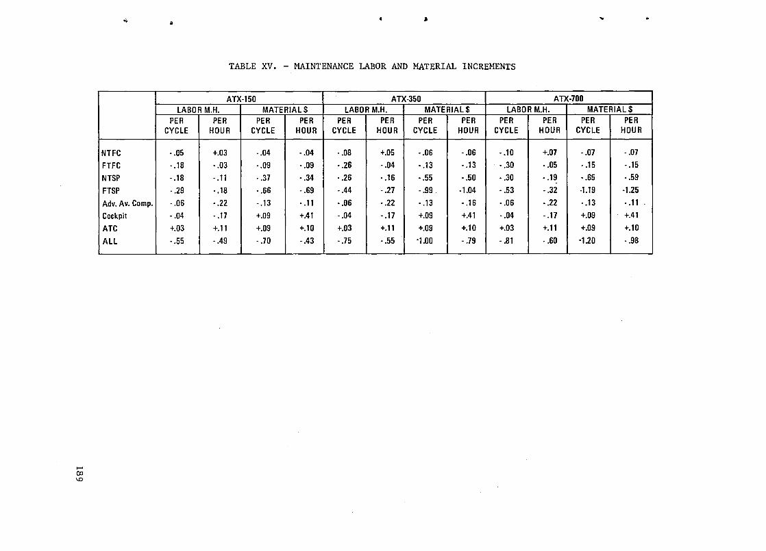
...... 00 \0
..
NTFC
FTFC
NTSP
FTSP
Adv. Av. Camp.
Cockpit
ATC
ALL ~---
~ ~ '"
TABLE XV. - MAINTENANCE LABOR AND MATERIAL INCREMENTS
ATX·150 ATX·350 ATX·700 LABOR M.H. MATERIAL$ LABOR M.H. MATERIAL$ LABOR M.H. MATERIAL$
PER PER PER PER PER PER PER PER PER PER PER PER CYCLE HOUR CYCLE HOUR CYCLE HOUR CYCLE HOUR CYCLE HOUR CYCLE HOUR
·.05 +.03 ·.04 · .04 · .08 +.05 • .06 · .06 • .10 +.07 •. 07 · .07
· .18 · .03 ·.09 · .09 • .26 · .04 · .13 • .13 • .30 • .05 ·.15 • .15
· .18 · .11 · .37 • .34 · .26 • .16 ·.55 • .50 • .30 • .19 ·.65 · .59
· .29 • .18 · .66 ·.69 ·.44 · .27 · .99 ·1.04 • .53 · .32 ·1.19 ·1.25
· .06 · .22 • .13 • .11 • .06 · .22 • .13 • .16 · .06 • .22 . . 13 • .11 .
· .04 • .17 +.09 +.41 · .04 · .17 +.09 +.41 ·.04 · .17 +.09 +.41
+.03 +.11 +.09 +.10 +.03 +.11 +.09 +.10 +.03 +.11 +.09 +.10
• .55 • .49 · .70 ·.43 • .75 • .55 ·1.00 · .79 • .81 · .60 ·1.20 • .98

maintenance has been increased, but instrument maintenance has been virtually eliminated. The Air Traffic Control (ATC) configuration shows increased maintenance because electronics equipment has been added with relatively minor reduction in flight hours.
8.4 New Technologies and Additional Benefits
In investigating the new technologies, some items were discovered which were not incorporated in the basic study, i.e., the configurations previously described. They were not incorporated for various reasons: the technology was not known or not known in sufficient depth in time, the benefits could not be calculated with a sufficient degree of confidence, new data became available which might affect previous evaluations, or the mechanization could not be conceptualized in sufficient detail to permit penalty evaluation with confidence. These new inputs were evaluated and, where appropriate, the benefits and penalties estimated. These new inputs were not evaluated by the methods used in the basic study. These new and additional benefits have been included as increments (cross hatched) in the Results Section 9 and could be considered as a liberal or optimistic viewpoint as opposed to the conservative viewpoint of the basic study.
The items considered and included as additional benefits:
• Tail downsize
• Two versus three-man crew
• Additional SFC versus bleed benefit
• Detailed drag penalties
Reduced nacelle drag
Reduced inlet capture area
Fan air for precooler .
Pylon downsize
Splitter downsize
Reduced ECS heat exchanger drag
Reduced generator and hydraulic heat exchanger drag
• Remove engine blowout doors
• Use electric fuel and lube pumps
190
...
..
"'"

..
"
•
do
>~
• Bleed port mechanization penalty
• Thrust downsize of engine
• Advanced wire and magnetics
• Electric wheels
• Powered brakes
The following items were considered, but not included, in the "additional benefits":
• Vortex driven turbines
• Laminar flow control
• Stored energy systems
8.4.1 Tail sizing. - Figure 46 shows the traditional horizontal tail sizing notch chart. The tail volume coefficient of 0.78 was used for all configurations evaluated, including the baseline; the tail was not downsized as more sophisticated flight control was added. This was because it would take additional wind tunnel data to show that a smaller tail had sufficient control power to bring the aircraft back to the operating point in gusts; this is a conservative approach. Others have proposed automatic angle of attack limiting to prevent deep stalls and have assumed that control in gusts can be obtained by high bandwidth control systems; this is a liberal view but may be true; Boeing Co. in their lAAC studies used a tail volume coefficient of 0.51, this would give an additional 1.2% improvement in DOC.
8.4.2 Two versus three-man crew. - A two-man versus three-man crew is an obvious saving but it was assumed in the basic study that labor relations would not allow a two-man crew for the ATX-350 and ATX-700 aircraft. Recent decisions in news reports have indicated that advanced displays and controls such as are included in the advanced cockpit configuration will allow use of a two-man crew; this will allow an additional three to four percent reduction in DOC.
8.4.3 Additional SFC benefits. - Additional SFC-versus-bleed benefit was postulated after receipt of new data from General Electric Company. The new information was developed by GE in studying advanced engines for the 150 passenger airplane initiated by Delta Airlines. This study showed additional SFC benefits in no bleed, and additional weight savings because of thrust downsizing and elimination of mechanization problems in bleed ports for high bypass (low core flow) engines. The SFC benefits resulted in an estimated 0.8% decrease in DOC and the weight savings resulted in 0.2% decrease in DOC.
191

TAIL VOL.
COEF.
.78
.51 PROVIDE • CL MAX • NOSE
WHEEL LIFT OFF
LOADING LIMITS
L.... ,-CONSERVATIVE VIEW
LIBERAL VIEW
• STALL RECOVERY • WITH FLAPS • HIGH SPEED
• CONTROL IN GUSTS
FWD +- CG LOCATION - AFT
Figure 46. - Tail sizing.
8.4.4 Detailed drag penalties. - Detailed drag penalties were not included in the basic studies, although some were included in the Johnson Space Center study, because conservative thinking dismisses them as too small to calculate. Figure 41 shows the conventionally mounted accessory drive occasioned by the number of accessories required in the conventional secondary power system; constant speed drive, generator, hydraulic pump, and starter turbine. With the advanced system, only the generator is needed which allows mounting in the pylon or even mounting directly on the fan shaft (integral).
The engine inlet can be reduced slightly in size because the bleed air need not be drawn through it. The bleed air precooler requires fan air for cooling which is not needed if no bleed air is used. The generator constant speed drive and the hydraulic system require cooling air which is not needed for the advanced systems. The advanced ECS system will use cooler air from the electrically driven compressor than from the engine bleed thus not as much
,1'
':
,~
•
cooling air will be required, a reduction in ram air drag. The pylon and .; splitter inside the engine can be reduced in size because they no longer accommodate the bleed air duct. Reduction of these small drag penalties result in a decrease in DOC of approximately 0.7%.
,.
192

..
t
"-
•
•
,.
8.4.5 Electric fuel and lubrication pumps. - The use of electric fuel and lube pumps instead of mechanical pumps can have several beneficial effects. The mechanical pumps must be oversized to allow large acceleration fuel flows at low rpm. Also, at high rpm much of the flow must be bypassed resulting in fuel heating. Electric pumps can be started before the engine thus ensuring a positive flow of fuel for reducing starting time. Electric pumps can also be simpler centrifugal pumps rather than gear pumps. The use of electric pumps is estimated to save 0.01% of DOC.
Advanced wire and magnetics technology under study at NASA Lewis Research Center are estimated to save 0.3% of DOC.
8.4.6 Powered wheels. - Powered wheels, that is wheels driven electrically by the APU for taxi, can reduce use of the main engine for taxi. This was not included in the basic study because mechanization of the system is not apparent, and design was not within the study scope. From a conservative viewpoint the installation penalties might outweigh the benefits. Nevertheless, the benefits are apparent and with best estimates of the installation penalties the benefit is still 1.0% of DOC.
NASA has already evinced interest in powered-wheel technology and some initial R&D work has been conducted by the Bendix Corporation on the utilization of a hydraulic "dynavector" as a means for taxiing aircraft without the use of, or the support of, aircraft engines; to this date, minimal work has been accomplished on electrically powered wheels. The main incentive for the pursuit of the powered-wheel technology is its fuel-saving potential, but there are other side benefits to be derived, not the least of which would be a mitigation of the tire and brake problem. Certainly, in the case of shorthaul transports making repeated taxi, takeoff, and landings, brake-overheating stands as pervasive-problem to be solved. The danger of brake-initiated fires is itself a constant concern and is resulting in the expenditure (by the military) of substantial R&D funds, directed towards the development of new non-flammable fluids.
Realistically, the utilization of powered wheels in large, and very large, transport aircraft will impose substantial power demands on the onboard APU and also upon the inverters necessary to program the required powercharacteristic to the wheel drive motors. As stated, in previous text of this report, the use of powered wheels for taxiing will introduce a new role for APUs in the future advanced transports, so it will not be possible to eliminate them, as is being presently proposed by some segments of the aerospace industry. These facts are therefore elements of the trade that must be pursued to determine the overall benefits of this technology. Certainly, powered wheels will add some weight to the aircraft and the mechanical implementation of the drives will add a degree of complexity to the wheels. However, the major advantages would be the fuel savings incident on the ability to shut down two, or more, engines during taxi; the reduction in logistic support; and the savings in capitalized equipment, presently committed to the present type of aircraft limited-towing operations. The term "limited" is
193

used because there are some proponents of the concept that the tow trucks could be used to tow the aircraft out to near the takeoff point, where the engines would then be started from onboard APUs. An extension of this philosophy, might presuppose the adding of engine start facilities to the truck itself; such a proposal would come again from the advocates of APU elmination.
The subject of powered wheels is therefore in need of further treatment in future NASA studies. Such studies must start with a vigorous analysis of the benefits of powered wheels and, its alternatives. Design work, both electrical and mechanical would have to be accomplished to define some realistic implementation methods for powered wheels in future aircraft. This phase would also define the breakaway forces relative to different size aircraft, and it would define the horsepower requirements for taxiing speeds from 15 to 25 mph. With the power requirements so established, motor-sizing and inverter sizing would be accomplished based on multi-wheel bogie configurations. At this point, technical specifications, or briefs, would be written to permit specialist aerospace electrical suppliers to size the motors and the static power supplies: the prime contractor would be responsible for the overall design of the control system, as well as the iterative studies (using in-house computer programs; such as ASSET). These computer programs would define the mission fuel, and the fuel savings vis-a-vis other aircraft taxi/towing methods.
8.4.7 Electric brakes. - To some extent, electric brakes complement the benefits ascribed to powered wheels. The trend in future aircraft, using the advanced technology engines, is for the engine rpms and thrust utilized in taxi to increase. As a consequence, conventional engine taxi methods are likely to result in an increased riding of the brakes and an exacerbation of the brake and tire problem. With the utilization of powered wheels, electric brakes could act cooperatively with the wheel drive motors and therefore mitigate the brake and tire problems.
To date, minimal work has been accomplished relative to electric brakes, but at this time, it is envisioned that electric brakes will be no more than an electro motive method of actuating the thrust plates on an otherwise fairly conventional friction plate clutch. In the previous NASA-JSC/LCC program, a schematic was included in the NAS9-15863 July '81 report, which showed a "ring-motor" that operated, via a Saginaw-type high efficiency screw-jack onto the conventional brake friction plates. This approach is one of a number of options that could be investigated; indeed, there is a possibility that an electroviscous approach might be practical and viable in.that it would not utilize external conventional hydraulics; it could, however, take advantage of the performance of a viscous-type coupling.
Goodyear is presently active with approaches to all electric brakes and this work will complement other prospective solutions to the implementation of electrically actuated brakes. Some of these approaches could include multiple motor drives (with or without screwjacks) as well as other more novel
194
","
•

...
,.
~
..
•
~
",
methods. It will therefore be necessary, in the ensuing work, to conduct meaningful trades that will identify and exploit the merits of the different candidate approaches. Conventional hydraulically actuated brakes enjoy a significant heritage of experience and they represent formidable competition with respect to reliability and performance for electric brake systems. Fast progressive braking, fast brake release functions are critical to proper aircraft control, during the landing run; also, the braking-energy and the heatdissipation associated with decelerating aircraft with landing weights of over 300,000 pounds and landing-speeds of over 120 knots pose significant challenges for the electrically actuated brake systems.
8.4.8 Vortex driven turbines. - This, again, is another technology area in which NASA-LRC has made a unique contribution. Through some initial wind tunnel work ~based on James C. Patterson's invention "Wing-tip Vortex Turbines"), wing-tip mounted turbines offer the potential for reducing the drag coefficient along with the prospects of electric power generation. Typically, as illustrated in figure 47, the plot of CD vs. C shows that the wing-tip turbines have an "end plate" affect in which a CD ~ecrement can be achieved with the turbine at zero rpm and a lesser drag-decrement when the turbine is allowed to rotate. Figure 48 is another curve plot (taken from J. C. Patterson's presentation-data) showing the potential for extracting relatively large amounts of mechanical power from the wing-tip turbines. Evidently, if such turbines were geared to drive samarum-cobalt generators, such vortex driven power generators could work very synergistically with the primary power generation system in the all electric airplane. Any realistic and practical implementation of vortex driven turbines could therefore offer the following advantages:
1. A prospective reduction in aircraft drag at typical cruise CL values
2. Vortex-wake dissipation by extracting energy from the wake.
3. Electric, or other, power generation means.
4. A source of emergency power in the utilization of the turbinegenerators as RATs (ram-air turbines).
Each of the foregoing offer their own unique payoff: (1) is a fuel-saving benefit, (2) permits a closing up of the spacing between landing aircraft, (3) provides an additional type of power source in the all electric airplane, (4) provides an air driven source of electric power in the event of an allengine-out emergency condition.
It is clear that if the above benefits of vortex driven turbines can be maximized, then further research and development is justified to bring the technology to a state where such a technology assessment can be made. Clearly, in the trade analysis that will be conducted, it will be necessary to trade the fuel benefits of wing-tip extensions versus the complication of wind turbines, mechanical gearing and a generator installation, etc., Propeller
195

CD
196
0.032
0.022
0.020
0.018
0.016
Turbine blade configuration
o Cambered
+ Wing alone
2100 o
I . I I _ ' ..-,-0.014 -0.1 0 0.1 0.2
CL
Figure 47. - Wing tip vortex turbine, CD vs. CL
•
RPM 2439
o
..
. (
,~
.'t

..... \0 --..j
!> *-.. )< '<
800
Blade configuration
600 ~ 0 Symmetrical
o Cambered
o Tapered
HP Full scale 400
OLI ____________ ~ ____________ ~ ____________ L_ __________ ~ ____________ ~ ____________ ~
o 2 3
Angle of attack, a
Figure . Wing Tip Vortex Turbine
One wing panel
4
Figure 48. - Wing tip vortex turbine, hp vs. angle of attack.
5 6

optimization studies must be conducted in detail to evaluate different plan forms, thickness/chord ratios and twist; the benefits of ducted fans, fixed pitch and constant speed propellers must also be assessed. The realism of achieving meaningful Cn reductions with the turbines in a rotating and nonrotating mode must be established by wind tunnel ·programs and the comparative payoffs, relative to different aspect ratio, camber, wing sweep, etc., must be assessed by computer aided programs. Aerodynamic analyses will comprise a major part of any future work in this technology area, but parametric sizing of the turbines to determine power extraction capabilities must be explored, along with the electrical and mechanical design aspects of the turbines and the rotating machinery. Other, physical design aspects that must be evaluated would include the impact of the turbine installation upon the structural wingdesign (relative to wing-aeroelasticity, flutter-mode suppression, etc., in high-aspect-ratio wing configurations).
The benefits of Vortex driven turbines were not included in either the basic study or the "additional benefits" (cross hatched in the Results Section 9.0).
8.4.9 Laminar flow control. - This technology has been subjected to critical analysis for many years, because of the highly attractive benefits that accrue to an advanced technology air transport, when the wings and empennage are laminarized to 65% or 75% of the wing chord. The reduced drag, and the increase in the L/n ratio, offers prospective fuel improvements of 25% and more. Because of the major fuel saving potential of LFC, NASA has identified it as one of the technologies high on the list in the Aircraft Energy Efficient (ACEE) program for further examination and evaluation.
Natural and controlled LFC, which inhibits boundary layer separation, are the key objectives that must be addressed. in advanced aero foils having large regions of supercritical flow. The design of aero foils with large chord length laminar flow and the utilization of LFC with supercritical aero foils are the areas for evaluation by computer modeling and by the wind tunnel method. However, with the sharply increasing capabilities, implicit in computer modeling and computer analysis, it is becoming possible to determine flow fields and forces on complex aero foil shapes, by developing numerical solutions to equations-of-motion, which may be difficult to accomplish in the wind tunnel. Therefore, the· ability to compute flow fields in the transonic zones and the ability to analyze shock wave effects are the significant capabilities of the computer.
In the ensuing work on LFC, the other major focal points are the mechanical implementation of the technology; the determination of the suction flow rates, and the methods of laminarization of the upper and lower wing surfaces. Present work in the technology of LFC has concentrated on the use of porous glove panels of fiberglass construction, which are attached over a basic primary wing structure of say graphite/epoxy. These glove panels, utilizing porous materials or· titanium skins (over graphite/epoxy structure) with suction slots, have been the test methods employed for evaluating the
198
.,
..
c·
,,,.

~
1
4..
..
~
'")
efficacy of different LFC implementation methods. The major problem resident in most of these designs, however, has been and continues to be the problem of insect excrescence build-up. To date, the problem of insect contamination of the wing leading edge is the major factor inhibiting the efficiency of the LFC system; a concomitant aspect of this is the maintenance upkeep to ensure scrupulously clean aerodynamic surfaces. To some extent, the problem of leading edge contamination might be mitigated by the design of small radius leading edge curvatures, and the adoption of a concave aerodynamic camber on the forward lower surface of the aerofoil. Such a design might eliminate the need for providing suction capability in the leading edge region.
From the standpoint of the all-electric airplane, the pertinent technology interest would be in the electrodynamic method by which generation of the aerodynamic suction flow rates over the surfaces of the wings and empennage would be achieved. Presently, engine bleed air is the primary candidate for providing the energy for the LFC, so its elimination and its substitution by an electric energy source would be the objectives of the all-electric airplane approach. The study would therefore require parametric determinations to be made for different-size aircraft of the suction flow rates and the suction pressures required to induce laminar flow over the aerofoil surfaces. From the suction flow demands, horsepower estimates would be made pursuant to the electrical and mechanical design aspects of the motordriven compressors. By making these parametric estimates of the hp requirements for large aircraft in excess of 600 to 700 klb TGOW, the impact of these demands on the kVA-capacity of electric-generators could be determined. As an attractive and novel prospect it is possible that the utilization of electric energy. from vortex driven turbine generators could become the energy source for LFC and this would then remove this load from the aircraft's primary power-generation system. These and other aspects are the potential benefits of applying LFC in the all electric airplane.
The benefits of laminar flow control were not included in either the basic study or the "additional benefits" (cross matched in the Results Section 9.0).
8.4.10 Stored energy systems. - Historically, aircraft power systems have been plagued by extremely high short-time peak-power demands, which have had the effect of sizing, for example, the hydraulic system, in terms of the displacement of the engine-driven pumps and the flow capacity of the hydraulic lines. Typically, these large short-time power demands come from the landing gear, flaps, slats, thrust reversing functions etc. These are the loads that are the candidates for operation from some type of stored energy system.
In the further studies of the all electric airplane there is the possibility that a number of innovative approaches can be made towards satisfying the short-time power demands of the above type loads. However, it is of some relevance that the electric system itself is not so impacted by short-time power demands, because the rotating electric machinery and the electric wire have excellent short time electrothermal characteristics: nonetheless, the development of new approaches to stored-energy systems can result in a
199

reduction in the gage of the electric wire used for these loads and offer the possibility for the installation of dedicated self-contained power-systems in some discrete areas. One of the more basic approaches to stored energy is to consider the use of mechanical energy, as might be stored in a relatively small high speed flywheel. With the development of high speed switching static inverters, it is possible to program the output power characteristics of the inverters to "pump up" the flywheel to a high speed over a comparatively long length of time; the energy so imparted to the fly-wheel could then be extracted when so required. It is clear from the potential of electromechanical stored energy system that a number of loads in the all electric airplane could be powered by such novel means.
The benefits of stored energy devices were not included in either the basic study or the "additional benefits" (cross hatched in the bar charts of Section 9.0).
9. RESULTS
The output of this study includes the technology selection matrix and listings of Section 6 as well as the payoffs described in this section. The payoffs were obtained from the ASSET computer outputs for each of the 8 configurations for evaluation. The outputs of weight, block fuel and DOC for each configuration were subtracted from the baseline configuration output to give the savings shown in the following bar charts.
Figure 49 shows the saving in direct operating cost (DOC) for near term and far term for the 350 passenger aircraft for the average stage length. The bars are broken down into fuel, maintenance, depreciation, crew, and insurance for those instances where the item is of significant size. Figure 50 shows the same data for all configurations in the far term. The "all" configuration is one which includes all of the technologies incorporated in the other configurations, however, it is not just the addition of the other benefits. It is a separate configuration, run through ASSET. It is approximately 10 percent less than the addition of the parts. Figure 51 shows the same data for the 150 passenger aircraft.
Figure 52 and 53 show the output for gross takeoff weight (TGOW). At GTOW the ATX-350 can fly a 8500 km (4600 n.mi) mission with reserves remaining.
Figures 54 and 55 show data for fuel savings.
Note that the DOC, GTOW, and fuel savings all follow the same pattern. The ATC is the largest payoff, FTSP and FTFC are large with FTSP the larger. Components and cockpit are relatively small but it should be kept in mind that the corresponding investment is small and also that they are enabling technology for the other configurations. The components technology is used extensively in all other configurations and the cockpit technology makes feasible a two-man crew and the ATC benefits.
200
~
,i
,.,

-'"
>,
"-
.-
,
-",
% DOC
40083
% DOC
10
8 ~
6 ~
4 r-
2 r-
o
12
10 f--
8 -
6 r-
4 ~
2 -
o
FLIGHT SECONDARY CONTROL POWER
FUEL
FUEL MAINT FUEL
FUEL MAINT DEP I
NTFC FTFC NTSP FTSP
Figure 49. - DOC savings, flight control and secondary power • ATX-350, 2500 n.mi.
FUEL
G MAINT
DEP
FTFC FTSP , ADV. AV. COMPo
, •
FUEL
FUEL
MAINT
MAINT
DEP DEP
, COCKPIT ATC ALL
Figure 50. - DOC savings major technologies, ATX-350, 2500 n.mi.
201

14
12 I-
10 I-
SAVING - 8 I-
%OF fUEl DOC 6 -
4 - MAINT
DEP
2 -fUEL
0
fUE~~ MAINT MAINT
CREW
I fUEL , DEP , MAIN
FTFC FTSP ADV. AV. COMPo COCKPIT ATC
CONFIGURATION
40083
Figure 51. - DOC major technologies, ATX-150, 400 n.mi.
20
15
SAVINGS -1000 10
POUNDS
5
o
40083
FLIGHT CONTROL
~ NTFC
SECONDARY POWER
fUEL
fUEL
STRUC.
STRUC. SYST
FTFC NTSP
Figure 52. - GTOW savings, flight control and seco!::::::::y secondary power, ATX-350.
202
1 <
fUEL
MAINT
DEP
CREW
I ALL
J.i;
.,
fUEL
STRUC.
SYST
I,
FTSP
,.,

,'\.
),
'I-
;.
\
.-,
50
45 f-
40 f-
35 f-
30 r-SAVINGS -
1000 25 r-POUNDS
20 l-
15 f-FUEL FUEL
10 I-STRUC.
FUEL 5 I- " STRUC.
STRUC. SYST
0 SYST
FTFC FTSP ADV.AV. COCKPIT ATC COMPo
Figure 53. - GTOW savings, major technologies, ATX-350.
SAVINGS -% OF
BLOCK FUEL
40083
10
8
6
4
2
o
-
-
-
-
FLIGHT SECONDARY CONTROL POWER
I
NTFC FTFC NTSP FTSP
Figure 54. - Fuel savings flight control and secondary power, ATX-350, 2500 n.mi.
FUEL
i
I STRUC.
1 SYST I ALL
203

16
141-
12[ SAVINGS - 10
%OF BLOCK FUEL
81-
61-
I 0
FTFC FTSP ADV. AV. COCKPIT ATC ALL
40083 COMPo
Figure 55. - Fuel savings major technologies, ATX 350, 2500 n.mi.
Figure 56 shows all three aircraft together with average stage length and design mission. Note that the shorter stage length always provides more benefit because of the ATC sensitivity to number of takeoffs and landings. The sensitivity is less for the long-range ATX-350. The flight control benefits are relatively small for the ATX-150 because the small aircraft has a relatively simple inexpensive flight control system in the baseline.
Figures 57 through 71 are bar charts showing the savings in DOC, GTOW, and block fuel for each of three airplanes for two-stage lengths. The crosshatched portion at the top of each bar is the additional benefits as described in Section 8.4. These additional benefits (crosshatched on the bar charts) represent the liberal or optimistic view point of the benefits whereas the bar excluding the crosshatched area represents the conservative view point.
For the ATX-150 the near-term flight control (NTFC) usually results in a negative benefit (a net penalty), in the conservative view point, because the baseline flight control system is simple and inexpensive (manual). The larger aircraft require full power actuators even in the baseline so the change to advanced flight controls does not greatly increase the weight or cost. The sources of additional benefits are discussed in section 8.4. Basically they are as follows:
204
'.
(
.to'
...
,-,

\.'\,
14
:J 12
10
8
COMPONENTS COMPONENTS
~COCKPIT / I:S:~OCK"T FLIGHT CONTROL FLIGHT
I-CONTROL
/ -~
SEC.
II 1\ POWER ~
1/ ~ I-% OF
DOC SEC. POWER
6 I-ATC
4 I-
ATC
2 I-
., 0 ------
,400 NM 1 SOO NMI .. 1000 NM 3000 NM , I \ 2S00 NM 4600 NMI ..
ATX-1S0 ATX-3S0 ATX-700
... Figure 56. - DOC savings vs aircraft size and stage length. I ~
DOC SAVINGS DUE TO TECHNOLOGY 16 ATX-150, 400 NM AV STAGE LENGTH
14
12
SAVING - 10 FUEl
% OF DOC 8
FUEl
6 MAINT
4 c\ MAl NT
DEP DEP
MAl NT CREW CREW
-c' NTFC rltl. I1I.,r FTSP ADV.AV.COMP. COCKPIT ATC ALL
CONFIGURATION Figure 57. - DOC savings ATX-150, 400 n.mi.
205

206
% OF DOC
% DOC
16rl----------------------------------------------------------,
14
12
FUEL
6
4 FUEL
2 FUEL MAINT
FUEL CREW 0' I ,
NTFC FTFC NTSP FTSP ADV. AV.COCKPIT ATC ALL COMPo
Figure 58. - DOC savings, ATX-150, 1500 n.mi.
18
14
10
6
2
NTFC FTFC NTSP FTSP ADV. AV. COCKPIT ATC ALL COMPo
Figure 59. - DOC savings, ATX-350, 2500 n.mi.
,~,
("
-,,',
,4
,-

~
J
>I
oj
\
~,
20ri--------------------------------------------------------------------------~
18
16
14
(.) 12 o o ~ 10
'I-8
6
4
2
FUEL
FUEL I I FUEL
0' r===l t====1
(.) o o u. o 'I-
NTFC FTFC NTSP FTSP ADV. AV. COCKPIT ATC ALL CaMP.
Figure 60. - DOC savings, ATX-350, 4600 n.mi.
24r,-------------------------------------------------------------------------, 22 20 18
16
14
12
10 FUEL
8
6 FUEL
4 MAINT
2 FUEL OEP
OEP
o I I' --- I r;:;:;c' NTSP . F;~P' ADV. AV. ~~g~~T 7rf ALL
CaMP.
Figure 61. DOC savings, ATX-700, 1000 n.mi.
207

rt
20
18
16
14
0 12 0 c u.. 0
10 *-
8 FUEL
6
4
2 MAINT ,i
J rl/:U:1 I FUEL
NTFC FTFC NTSP FTSP ADV.AV. COCKPIT
DEP
ALL COMPo "':1
Figure 62. - DOC savings, ATX-700, 3000 n.mi. 11
10
9
8
7
6 1000 FUEL
POUNDS 5
4
3 SYST
2
, .... o I U333J33Jj ':SIKU~I' ~ I~'HU{;TI
ALL NTFC COMPo
208 Figure 63. - GTOW savings, ATX-ISO.

~
50~ GlOW SAVINGS, AlX-350 45' POSSIBLE ADDITIONAL BENEFITS
40
35
30 SAVINGS -
1000 25 POUNDS
20
15
10
\.' 5
NTFC FTFC NTSP FTSP ADV.AV. COCKPIT ATC ALL
'J./ CaMP. Figure 64. - CTOW savings, ATX-350.
80
70
60
50 CI) I FUEL C Z ::J
~ 40 0 0 0
30
2J ~ • • ISTRUCT
1
10r ~-::l ISTRUCTI I:j r::l I SYST
SYST
"" 0 1 1 1 1 1 1 NTFC FTFC NTSP FTSP ADV. AV. COCKPIT ATC ALL
CaMP.
Figure 65. - CTOW savings, ATX-700.
209

22
20
18
16
14
% 12 OF BLOCK FUEL 10
8
6
4
2
0
20
18
16
14
12
% OF 10 BLOCK FUEL
8
6
4
2
0
210
NTFC FTFC NTSP FTSP ADV. AV. COCKPIT - COMPo
ATC
Figure 66. - Fuel savings - ATX-150, 400 n.mi.
NTFC FTFC NTSP FTSP ADV.AV. COCKPIT ATC COMPo
Figure 67. - Fuel savings, ATX-150, 1500 n.mi.
~
,~
ALL
<.:'
[)
'" ALL

\
.)
\J
c.J
\
,""
22~1--------------------------------------------------------~
20 18
16
14
12
SAVINGS -% OF 10
BLOCK FUEL 8
6
4
2
0' , " ,~ NTFC FTFC NTSP FTSP ADV. AV. COCKPIT ATC ALL 40083
COMPo
Figure 68. - Fuel savings, ATX-350, 2500 n.mi.
20
18
16
14
...J w it 12 ::.: u 9 10 m u.. 0
'*' 8
6
4
2
0 NTFC FTFC NTSP FTSP ADV. AV. COCKPIT ATC ALL
COMPo
Figure 69. - Fuel savings, ATX-350, 4600 n.mi.
211

212
25~i-------------------------------------------------------------'
... w
20
it 15 ~ u a ... III u.. a cf. 10
5
Oi~-L ____ L-~ ____ L-~ ____ ~~ ____ ~~====~~ ______ ~L-__ ~~ __ --'~~
NTFC FTFC NTSP FTSP ADV. AV. COCKPIT ATC ALL COMPo
Figure 70. - Fuel savings, ATX-700, 1000 n.mi.
20
15
... w ::J u.. ~ U a ... III 10 u.. a cf.
5
NTFC FTFC NTSP FTSP ADV. AV. COCKPIT ATC ALL COMPo
Figure 71. - Fuel savings, ATX-700, 3000 n.mi.
,,".
(.I
j
\.~,
[.
,-..,

.,
)
)J
0-
1
"'"
NTFC I FTC
Horizontal Tail Resizing
NTSP I TFSP
Engine SFC and drag benefits
Components - None identified
Cockpit - two-man vs three-man crew in ATX-350 and ATX-700
ATC - Powered Wheels
The benefits follow the same pattern from aircraft to aircraft and from range to range as discussed relative to figure 56. The ATC is always the largest benefit but relative to itself is largest on short ranges and smallest on long ranges. The benefits of flight control and secondary power are obtained mainly in cruise portions of the flight and therefore show up best on the longer ranges. Components and cockpit benefits are relatively small but they are enabling technologies which are required for the other configurations also.
Figures 72 through 77 are charts of procurement cost savings and nonrecurring cost savings. Positive numbers are savings and negative numbers denote extra cost over the baseline. Procurement cost includes production cost plus training, handbooks and spares. The nonrecurring costs include engineering and development.
213

700
600 I-
500 l-
400 I-
t;: ct 5 300 l-a: < a: ~ 200 I--<I>
:.::
100 I--
0
-100 I-
-200
214
'--NTFC
4 4r
w 3 z ct ...J 0.. a: < a: w 0.. 2 <I>
10 o
iii t:J Z :> ct Vl
r
I-
I-
(
r---
r--- ( l
r---
r---
Il n U NTSP FTSP ADV.AV. COCKPIT ATC All
COMPo FTFC -..i
l':'
Figure 72. - Procurement cost savings, ATX-150.
Allr---
~
~ ~ FTFC .---
NTFC n COCKPIT
t)
-0 ADV.AV.
COMPo (,,\
Figure 73. '- Procurement cost savings, ATX-350.

.. 8
TOTAL $113 X 106/AIRCRAFT
7
6
5
Ii: « 4 a:: Co) a:: < 3 a:: w 0.. ...
CD 2 0
ADV.AV. COMPo
o FTFC NTSP FTSP COCKPIT ATC ALL
,,' ·1
? Figure 74. - Procurement cost savings, ATX-700.
+15 NTSP
FTSP +10
+5
COCKPIT ATC
.- 0 w w -' "-a:: -5 ALL w 0.. ADV.AV. (/) a:: COMPo « -'
-10 -' 0 0
CD -15 0
-20
.~
-25
NTFC -30
1"0 FTFC
.------
Figure 7S. - Savings nonrecurring costs, ATX-lSO.
21S

I;
100 FTSP
( I
80 All
~ 60 w w .... "-
ATC
a: w
40 Il. NTSP III a: <I: .... .... 0 20 c
(l)
0
0
-20 j
NTFC ADV.AV. COCKPIT
-40 FTFC COMPo
1,:'
Figure 76. - Nonrecurring costs savings, ATX-350. 140
~
120
100
l- n -
80 c-
60 ~
r-- r--
I -
w w .... 40 "- c-a: w Il. <I> 20 -
(l) 0 ADV.AV.
0 NTFC FTFC COMPo COCKPIT
NTSP FTSP ATC All
-20 I- r, "-----
-40 c-'----
-60 l- I......- 1'"\
-80 ------ ----
Figure 77. - Nonrecurring cost savings, ATX-700.
216

.\
)
'J
'J
J
"" , I
1. Report No. 2. Government Accession No.
NASA CR-165890 4. Title and Subtitle
ELECTRONIC/ELECTRIC TECHNOLOGY BENEFITS STUDY
7. Authorls)
W. W. Howison, M. J. Cronin
9. Performing Organization Name and Address
Lockheed-California Company P.O.Box 551 Burbank, California 91520
3. Recipient's Catalog No.
5. Report Date
May, 1982 6. Performing Organization Code
8. Performing Organization Report No.
LR 30079
10. Work Unit No.
11. Contract or Grant No. NAS 1-16199
12. Sponsoring Agency Name and Address
13. Type of Report and Period Covered Contractor Report
National Aeronautics and Space Administration Washington, DC 20546
15. Supplementary Notes
16. Abstract
Aug 1980 - Jan 1982 14. Sponsoring Agency Code
In this study, the benefits and'payoffs of advanced electronic/electric technologies were investigated for three types of aircraft. The technologies, evaluated in each of the three airplanes, included advanced flight controls, advanced secondary power, advanced avionic complements, new cockpit displaye, and advanced air traffic control techniques. For the advanced flight controls, the "near term" considered relaxed static stability (RSS) with mechanical backup: the far term considered an advanced fly-by-wire system for a longitudinally-unstable airplane. In the case of the secondary power systems, trades were made in two steps: in the near term, engine bleed was eliminated; then, in the far term bleed air, air plus hydraulics were eliminated. Using three commercial aircraft, in the 150, 350, and 700 passenger range, the study quantified by means of Lockheed's Advanced System Synthesis and Evaluation Techniques (ASSET) program, the technology value and pay-offs, with emphasis on the fiscal bene~ fits. Weight reductions deriving from fuel-saving, and other syetem improvements, were identified and the weight savings were cycled for their impact on TOGW (takeoff gross weight) and upon the performance of the airframes/engines. Maintenance, reliability, and logistic support were the other study criteria. The conclusions of the study are that all three aircraft benefit by the advanced avionic/electric technologies to a varying degree. The air traffic control technology, the all electric airplane, and advanced all-electric flight controls offered the most attractive pay-offs, with the other technologies offering lesser benefits. Typically, the study identified direct operating cost (DOC) reductions of 10% to 20% and weight reductions of 13,000 to 77,000 pounds. Details of fleet size, service life, fuel costs and other pertinent data are included in the report.
17. Key Words ISuggested by Authorls)) 18. Distribution Statement
Fly by wire, mUltiplexing, air traffic Unclassified - Unlimited control, all-electric airplane, energy Subject Category -efficient airplane, ECS, hydraulic systems, variable voltage, variable frequency
19. Security Classif. lof this report)
Unclassified 20. Security Classif. (of this pagel
Unclassified 21. No. of Pages
218
* For sale by the National Technical Information Service, Springfield, Virginia 22161
22. Price'
217

End of Document