electronic training board for mobile …repositorio.utn.edu.ec/bitstream/123456789/3776/2/04 red...
TRANSCRIPT
ELECTRONIC TRAINING BOARD FOR MOBILE
APPLICATIONS BASED ON ANDROID OPERATING
SYSTEM.
Edgar A. Maya, Byron R. Valenzuela
Abstract - This paper provides information on the design and implementation of an electronic trainer for mobile devices based on the Android operating system, this system includes several devices such as LEDs, switches, buzzer, relay, display's, temperature sensors and modules communication as GPS, Wi-Fi, Xbee, I2C, to make applications with the mobile and trainer.
Index Terms - Android, GPS, Wi-fi, Xbee, I2C
I. INTRODUCTION
The growth of technology and the great
reception of mobile based on Android operating system have made that development of a trainer for students of Engineering in Electronics and Communication Networks Universidad Tecnica del Norte, with which the same may make multiple applications based on mobile terminals with Android operating system and interact with the various peripherals with the trainer account.
This research document received on 12 October 2014 was conducted as a preliminary project for the professional degree in Engineering in Electronics and Communication Network Engineering, Faculty of Applied Science (FICA) of the “Universidad Tecnica Del Norte”
E. A. Maya works at the Universidad Tecnica Del Norte, in the School of Engineering in Electronics and Communication Networks, July 17th Av The Olivo, Ibarra-Ecuador (Tel: 5936-2955-413, e-mail:. Eamaya @ utn .edu.ec).
B. R. Valenzuela, a graduate of the School of Electrical Engineering and Communication Networks (Phone: 5936-2604-664, e-mail: [email protected]).
The modules and peripherals that the
student will have available for to make
applications are: digital input / output,
LED's, digital analog converters, matrix
keyboard, LCD 16x2, switches, matrix
LEDs, buzzer, communication: Serial,
pWM, I2C, Xbee, Bluetooth, GPS, Wi-fi
and temperature sensor module. Thus
promoting the technological development
of the education and growth of knowledge
by students.
II. BASICS CONCEPTS
A. What is IOIO?
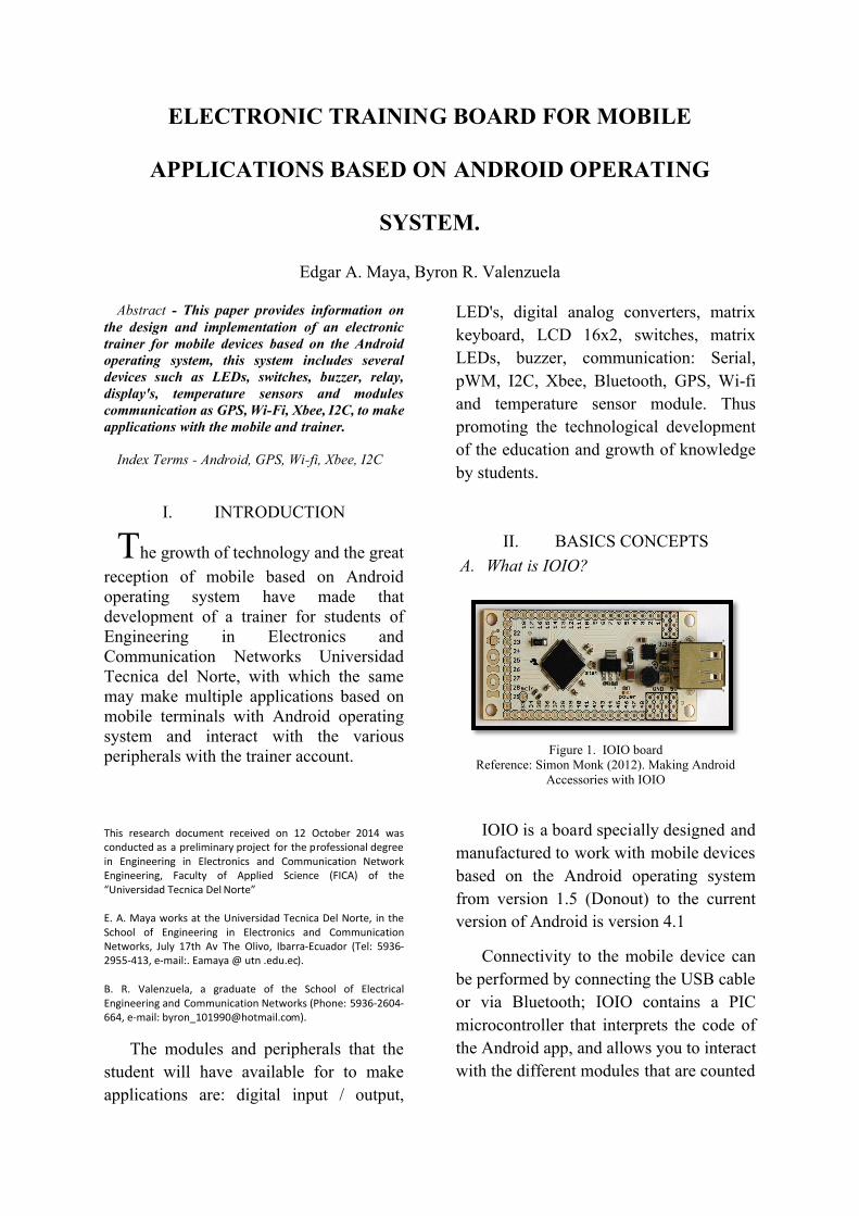
Figure 1. IOIO board
Reference: Simon Monk (2012). Making Android Accessories with IOIO
IOIO is a board specially designed and
manufactured to work with mobile devices
based on the Android operating system
from version 1.5 (Donout) to the current
version of Android is version 4.1
Connectivity to the mobile device can
be performed by connecting the USB cable
or via Bluetooth; IOIO contains a PIC
microcontroller that interprets the code of
the Android app, and allows you to interact
with the different modules that are counted
as: Digital Input / Output, PWM, analog-
digital converters, I2C, SPI, UART.
B. Characteristics and structure of the IOIO board The IOIO board weight 13gr., 6,8cm
long by 3cm wide, physically has 55 pins,
is powered by an external source between
the GND and Vin pin has a micro USB
socket for which connected with an adapter
cable to the Android mobile device, has two
LEDs, one LED indicates when the board is
powered and the other if the board could
connect to the Android device.
IOIO contains a PIC microcontroller
family 24FJ128DA210, which is a 16-bit
microcontroller which work as a host which
receives instructions from the Android
application installed on the mobile device.
This microcontroller has a modified
Harvard architecture, 8MHz internal
oscillator and allows a current of 20mA
input and output on all ports.
The IOIO board contains the following
pins and components:
Micro USB connector (type A). - Micro
USB socket used to connect the mobile
Android.
GND Pins (9-pin). - Pines grounding.
VIN Pines. (3 pin). - Pines supply of
IOIO, the supply voltage range from 5V
to 15V.
5V Pines (3 pin) is used output. - 5V; it
can also be used as 5V supply.
Pines 3.3V (3 pin). - Output pins are
3.3V.
MCLR pin (1 pin). - This pin is only
used for updating firmware.
Power led. - Led lights when the IOIO
is fed.
Stat led. - Led lights when the IOIO
connects to the mobile device.
Charge current trimer (CHG). - Use to
adjust the amount of current supplied to
the USB VBUS line.
Input and output pins.- The input and
output pins of IOIO, are used to connect
external circuits to the various
interfaces of the board, all the IOIO
board pins can be used as digital inputs
and outputs of 3.3V.
o Pines and surrounded by a square,
can be used as analog inputs 3.3V
o Pines or circled, can be used as
inputs and digital outputs to 5V
tolerant.
C. Connecting the IOIO board
The IOIO integrates a firmware that
enables communication between mobile
Android and plaque, this firmware is
divided into two programs both are stored
in the flash memory of the microcontroller,
the programs are "application" and "boot
loader (bootloader) ".
The bootloader is the first program that
runs when the IOIO this firmware restarts
establishes communication between the
board and the mobile Android, checks
whether the written application code if so is
it running otherwise remains pending.
Applying this firmware communicates with
various libraries containing IOIOLib
control pins and internal modules.
Both wired communication such as
Bluetooth creates a socket for transferring
data and commands between the Android
device and the IOIO board.
D. What is Android?
Android is an operating system for
mobile devices like iOS, Symbian or
Blackberry OS, initially developed by
Android Inc. in 2003 and later purchased by
Google in 2005, based on the Linux kernel
2.6.0, which is responsible for manage
aspects such as security, memory
management, processes, networking and
driver model (drivers).
Android allows you to develop
applications using the SDK (Software
Development Kit), applications that can
take advantage of the various functions of
the mobile terminal such as GPS, camera,
contacts, accelerometer, calls, etc.
The programming language used to
create applications for Android is Java,
with the Linux kernel works Dalvik is a
Java virtual machine that runs on top of the
core system and allows running
applications.
E. Foundations for Android application
development
Android applications are written in the
Java programming language. The compiled
Java application, along with all the files that
are part of the application after being
compiled code in a package with the .apk
extension that is to be installed in the
mobile terminal Android.
Android SDK
Android SDK provides a number of
tools and API libraries required for creating
and debugging Android applications;
consists of several packets, then each
described them.
SDK Tools.
This package contains all necessary
information for debugging and Android
application testing tools, it is very
important to have this pack always
updated, is located in <SDK> / tools /.
Documentation.
A copy of the final documentation for
the Android platform APIs is in <SDK>
/ docs /.
SDK platform tools.
They are dependent on platform tools
necessary for developing and
debugging the application, is updated
when a new platform appears, is located
in <SDK> / platform-tools /.
SDK Platform.
There is a platform available for each
version of Android, android.jar includes
a package containing all the libraries for
application creation. To build the
Android application should declare that
platform will create the application. It is
located in <SDK> / platforms /
<android-version> /.
Sources for Android SDK.
It is a copy of the source code of the
Android platform, it is useful to step
through the code while debugging the
application. It is located in <SDK> /
sources /.
Samples for SDK.
Sample applications that can guide in
building the Android application.
Located in <SDK> / platforms /
<android-version> / samples /.
Google APIs.
An additional SDK that provides a
platform that can be used to develop an
application using the Google APIs,
Google APIs are used to create
applications that need the service
location.
Support Android.
It is a library that can be added to the
application and allows use APIs that are
not in the standard platform. <SDK> /
extras / android / support /.
Google play billing.
Provides libraries that integrate billing
services application with Google play.
<SDK> / extras / google /
Licencing Google play.
It provides libraries and examples to
carry out the verification of the license
application, when it is distributed in
Google play. <SDK> / extras / google /.
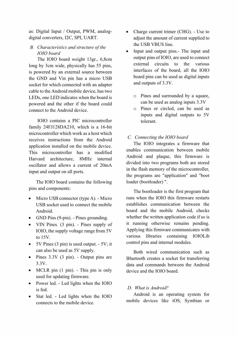
SDK Manager
The SDK manager shows the packages
that need updating, they are available, or
already installed the folders are separates
them into tools, platforms and other
components to facilitate the discharge.
Figure 2. Main Screen Android SDK Manager Reference: Prepared by Byron Valenzuela. Based on the
SDK Manager
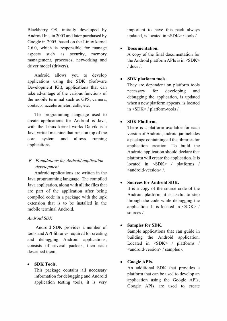
Android virtual device (AVD) The Android SDK includes a virtual
mobile device emulator called Android
Virtual Device (AVD), this mimics all the features of hardware and software of a real mobile device and allows you to check the performance of Android applications without the need for a real team.
Figure 3. Interface of an Android Virtual Device (AVD) Reference: Prepared by Byron Valenzuela. Based on the
AVD.
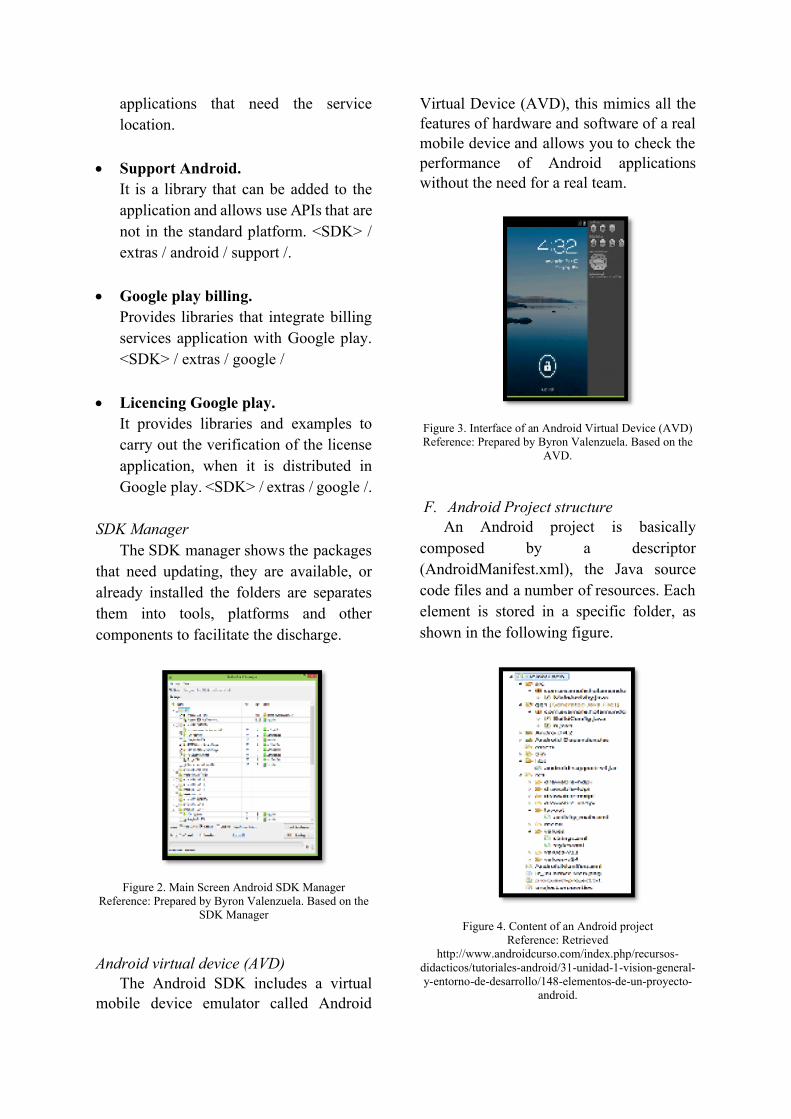
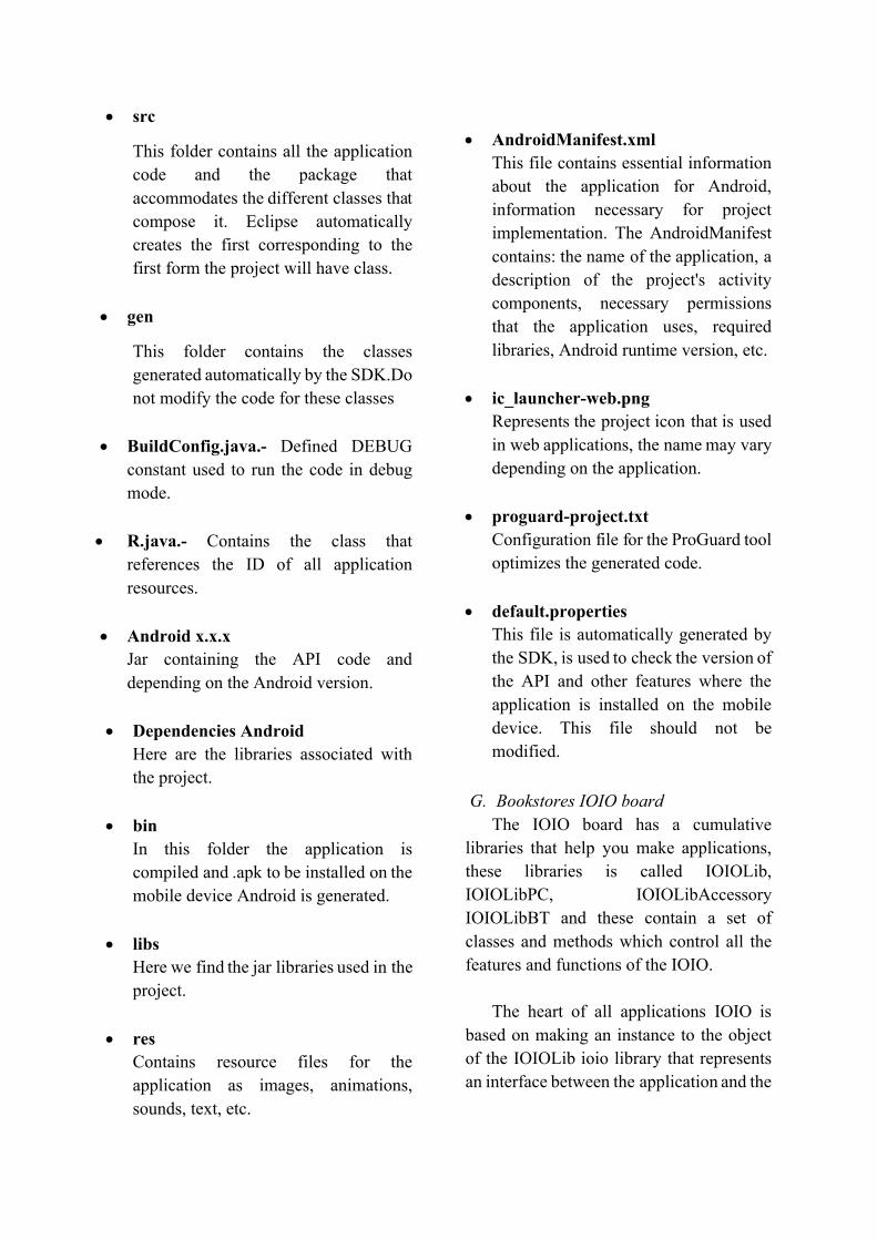
F. Android Project structure An Android project is basically
composed by a descriptor
(AndroidManifest.xml), the Java source
code files and a number of resources. Each
element is stored in a specific folder, as
shown in the following figure.
Figure 4. Content of an Android project Reference: Retrieved
http://www.androidcurso.com/index.php/recursos-didacticos/tutoriales-android/31-unidad-1-vision-general-y-entorno-de-desarrollo/148-elementos-de-un-proyecto-
android.
src
This folder contains all the application
code and the package that
accommodates the different classes that
compose it. Eclipse automatically
creates the first corresponding to the
first form the project will have class.
gen
This folder contains the classes
generated automatically by the SDK.Do
not modify the code for these classes
BuildConfig.java.- Defined DEBUG
constant used to run the code in debug
mode.
R.java.- Contains the class that
references the ID of all application
resources.
Android x.x.x
Jar containing the API code and
depending on the Android version.
Dependencies Android
Here are the libraries associated with
the project.
bin
In this folder the application is
compiled and .apk to be installed on the
mobile device Android is generated.
libs
Here we find the jar libraries used in the
project.
res
Contains resource files for the
application as images, animations,
sounds, text, etc.
AndroidManifest.xml
This file contains essential information
about the application for Android,
information necessary for project
implementation. The AndroidManifest
contains: the name of the application, a
description of the project's activity
components, necessary permissions
that the application uses, required
libraries, Android runtime version, etc.
ic_launcher-web.png
Represents the project icon that is used
in web applications, the name may vary
depending on the application.
proguard-project.txt
Configuration file for the ProGuard tool
optimizes the generated code.
default.properties
This file is automatically generated by
the SDK, is used to check the version of
the API and other features where the
application is installed on the mobile
device. This file should not be
modified.
G. Bookstores IOIO board
The IOIO board has a cumulative
libraries that help you make applications,
these libraries is called IOIOLib,
IOIOLibPC, IOIOLibAccessory
IOIOLibBT and these contain a set of
classes and methods which control all the
features and functions of the IOIO.
The heart of all applications IOIO is
based on making an instance to the object
of the IOIOLib ioio library that represents
an interface between the application and the
IOIO allowing control of all functions and
modules of the same.
All IOIO for Android applications
consist of the following features and
methods.
Current project class must extend the
class or AbstractIOIOActivity
IOIOActivity class, which allows you
to use the methods found in the libraries
of the IOIO.
An own class extended of
AbstractIOIOActivity.IOIOThread or a
class BaseIOIOLooper when use
IOIOActivity this class has all metods
of Android application that controls the
connection and use of the various
functions. Within this class is the
following methods.
o Method setup (); in this method
initializes and configures the
features that will be used in the
application. Example. The pin to be
used and the state will initially be
set, the pins that work with serial
communication module is
configured, the baud rate, parity,
etc. To instantiate class toward
IOIO is performed by ioio_.
o Method loop (); this method within
the Android application once the
connection is established develops,
it is an infinite loop where the
functions and features of the board
is controlled.
Both the setup () method and the loop ()
method throw exceptions allow
ConnectionLostException and
InterruptedException.
When an application is executable
automatically determined IOIO how to
connect either by USB cable or Bluetooth,
if the connection fails immediately the
application calls an incompatible () method
that verifies the cause and solution of the
problem, Failure to find the possible error,
the application calls a disconnected ()
method that makes the IOIO application is
aborted.
The IOIO Android applications require
permits for possible implementation, these
permissions are included in the
development of the Application in the
AndroidManifest of the project and
include: Bluetooth
(android.permission.BLUETOOTH) and
Internet (android.permission.INTERNET
(GitHub, 2008))
IOIO libraries has full control of all its
modules such as: digital input module and
output, digital analog converter, PWM
module, UART module, and I2C module.
III. ANDROID TRAINER DESIGN
AND BUILDING
A. Android trainer Overview
The trainer has eight sections, each
section is a module which to make
practices, each section has several
electronic elements according to each
module, also the trainer has a breadboard
included with the purpose to facilitate the
connection of devices that are not covered
by the trainer.
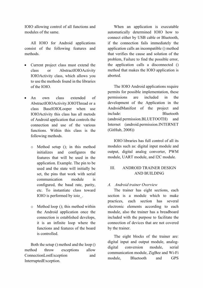
The eight blocks of the trainer are:
digital input and output module, analog-
digital conversion module, serial
communication module, ZigBee and Wi-Fi
module, Bluetooth and GPS
communication module, additional
modules, power supply, and breadboard
Figure 5. Overview trainer
Reference: Prepared by Byron Valenzuela.
The Bluetooth and GPS modules has
the connector mikroBus of
miKroelectrónica standard, this standard
makes the devices share the same
connection socket, eliminating the
connection of additional accessories for the
operation of equipment and the need for an
interface for each module is required to
connect.
Similarly ZigBee and Wi-Fi modules
have a common socket connection by booth
have the same dimensions, the socket
shared is XBee Explorer, this device has 10
pins, supply voltage regulated levels and
transmission and reception from 5V to 3.3V
module both ZigBee and Wi-fi modules.
Figure 6. Connector mickorBus (i) Connector Xbee
Explorer (d). Reference: (mikroElektronika, 2012), (Sparkfun
2012).
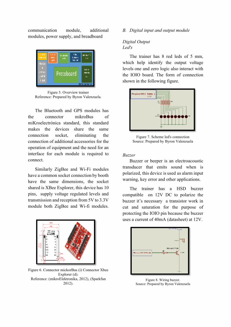
B. Digital input and output module
Digital Output Led's
The trainer has 8 red leds of 5 mm,
which help identify the output voltage
levels one and zero logic also interact with
the IOIO board. The form of connection
shown in the following figure.
Figure 7. Scheme led's connection
Source: Prepared by Byron Valenzuela
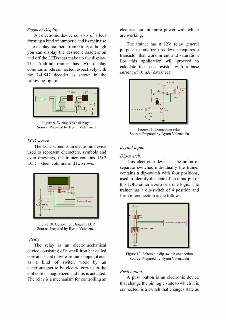
Buzzer Buzzer or beeper is an electroacoustic
transducer that emits sound when is
polarized, this device is used us alarm input
warning, key error and other applications.
The trainer has a HSD buzzer
compatible on 12V DC to polarize the
buzzer it’s necessary a transistor work in
cut and saturation for the purpose of
protecting the IOIO pin because the buzzer
uses a current of 40mA (datasheet) at 12V.
Figure 8. Wiring buzzer.
Source: Prepared by Byron Valenzuela
Segment Display An electronic device consists of 7 leds
forming a kind of number 8 and its main use is to display numbers from 0 to 9; although you can display the desired characters on and off the LEDs that make up the display. The Android trainer has two display common anode connected respectively with the 74LS47 decoder as shown in the following figure.
Figure 9. Wiring IOIO-displays.
Source: Prepared by Byron Valenzuela
LCD screen The LCD screen is an electronic device
used to represent characters, symbols and even drawings, the trainer contains 16x2 LCD sixteen columns and two rows.
Figure 10. Connection Diagram LCD
Source: Prepared by Byron Valenzuela
Relay
The relay is an electromechanical device consisting of a small iron bar called core and a coil of wire around copper, it acts as a kind of switch work by an electromagnet to be electric current in the coil core is magnetized and this is actuated. The relay is a mechanism for controlling an
electrical circuit more power with which are working.
The trainer has a 12V relay general purpose to polarize this device requires a transistor that work in cut and saturation. For this application will proceed to calculate the base resistor with a base current of 10mA (datasheet).
Figure 11. Connecting relay
Source: Prepared by Byron Valenzuela
Digital input.
Dip-switch. This electronic device is the union of
separate switches individually the trainer contains a dip-switch with four positions, used to identify the state of an input pin of this IOIO either a zero or a one logic. The trainer has a dip-switch of 4 position and form of connection is the follows.
Figure 12. Schematic dip-switch connection
Source: Prepared by Byron Valenzuela
Push button. A push button is an electronic device
that change the pin logic state to which it is
connected, is a switch that changes state as
long as you hold it. There are two types of
normally open and normally closed
switches.
The trainer has four normally open
switches connected in series with a 5V
resistor, the resting state is 0V, when active
the button the state change to 5V.
Figure 13. Connecting buttons with IOIO board
Source: Prepared by Byron Valenzuela
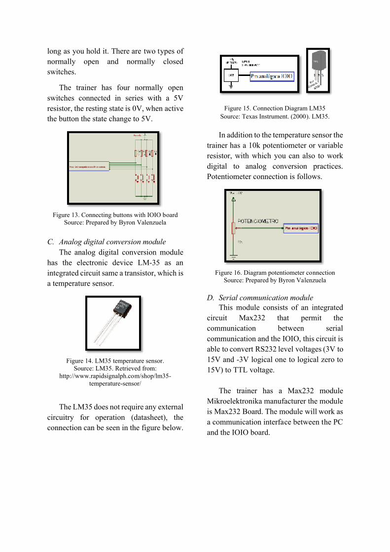
C. Analog digital conversion module
The analog digital conversion module
has the electronic device LM-35 as an
integrated circuit same a transistor, which is
a temperature sensor.
Figure 14. LM35 temperature sensor.
Source: LM35. Retrieved from: http://www.rapidsignalph.com/shop/lm35-
temperature-sensor/
The LM35 does not require any external
circuitry for operation (datasheet), the
connection can be seen in the figure below.
Figure 15. Connection Diagram LM35
Source: Texas Instrument. (2000). LM35.
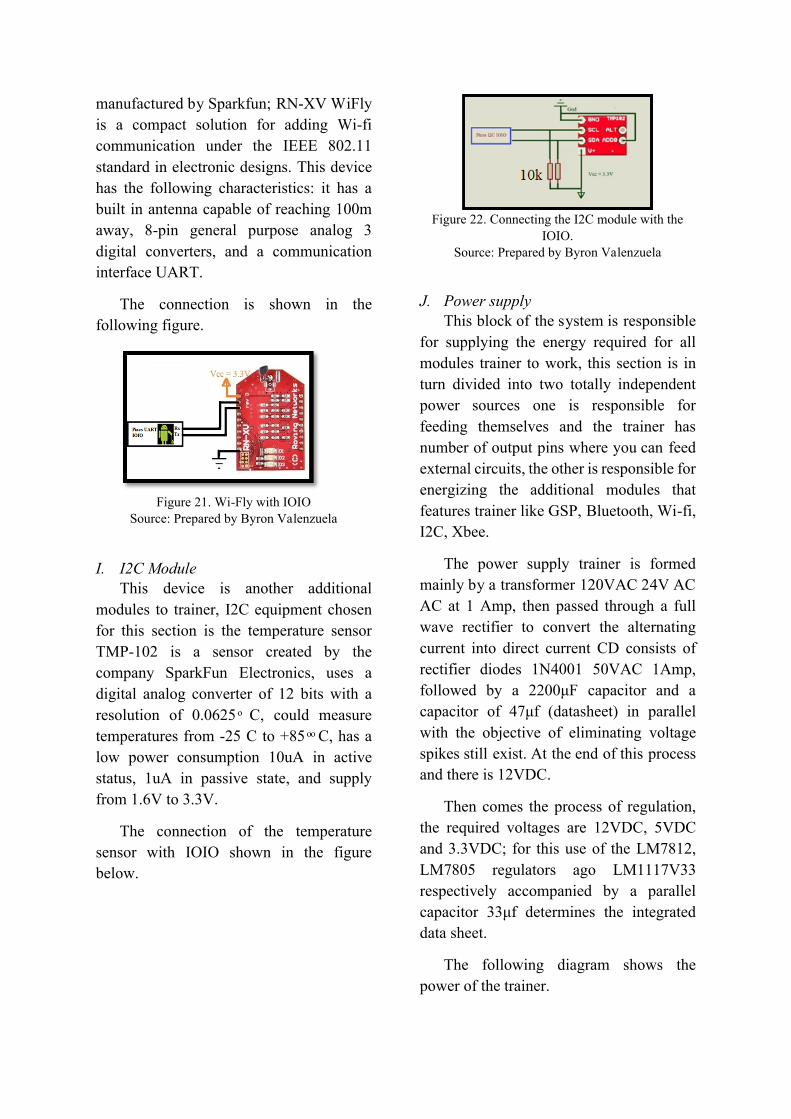
In addition to the temperature sensor the
trainer has a 10k potentiometer or variable
resistor, with which you can also to work
digital to analog conversion practices.
Potentiometer connection is follows.
Figure 16. Diagram potentiometer connection
Source: Prepared by Byron Valenzuela
D. Serial communication module
This module consists of an integrated
circuit Max232 that permit the
communication between serial
communication and the IOIO, this circuit is
able to convert RS232 level voltages (3V to
15V and -3V logical one to logical zero to
15V) to TTL voltage.
The trainer has a Max232 module
Mikroelektronika manufacturer the module
is Max232 Board. The module will work as
a communication interface between the PC
and the IOIO board.

Figure 17. Max232 Board. Reference: Max232 Board.
http://www.mikroe.com/add-on-boards/communication/max232/
E. ZigBee Module. This is additional modules to the trainer
this module is not part of the central board
of the trainer, but has a network socket to
easily connect and use it.
The trainer is a laboratory hardware that
will be used for academic reasons that
reason does not need many operating
distances or large transmission power, so
that the trainer has the XbeeS1® module.
And the connection is follow.
Figure 18. Connecting the IOIO Xbee®
Reference: Prepared by Byron Valenzuela
F. Bluetooth Module. The device chosen for this section is
the Bluetooth2 Click module by
Mikroelektronika, this device can reach a
coverage of up to 1000m, offers low power
consumption, and UART interface for
communication with external devices.
Stick Bluetooth2 communicates with
the IOIO by UART communication, and
the connection is as follows.
Figure 19. Module Click Bluetooth2
Reference: Bluetooth2 Click. Recovered:
http://www.mikroe.com/click/bluetooth2/
G. GPS Module. The GPS module adopted for this
section is the device GPS2 Click to
mikroelectronica, is a compact unit that
adapts to the network socket mikroBus, this
module supports navigation, location, and
industrial applications such as GPS C/A, S-
BAS, and A-GPS it supports
communication UART, SPI, I2C IS
configurable via jumpers on the board,
provides low power consumption and high
performance.
The device GPS2 interacts with the
IOIO Click through the serial
communication interface, because the
levels are not TTL UART is necessary to
use an operational amplifier to use the GPS
and how is this connection.
Figure 20. Click GPS2 connection with IOIO
Source: Prepared by Byron Valenzuela
H. Wi-Fi Module The Wi-fi device used for this section is
the RN-XV WiFly equipment
GND
manufactured by Sparkfun; RN-XV WiFly
is a compact solution for adding Wi-fi
communication under the IEEE 802.11
standard in electronic designs. This device
has the following characteristics: it has a
built in antenna capable of reaching 100m
away, 8-pin general purpose analog 3
digital converters, and a communication
interface UART.
The connection is shown in the
following figure.
Figure 21. Wi-Fly with IOIO
Source: Prepared by Byron Valenzuela
I. I2C Module This device is another additional
modules to trainer, I2C equipment chosen
for this section is the temperature sensor
TMP-102 is a sensor created by the
company SparkFun Electronics, uses a
digital analog converter of 12 bits with a
resolution of 0.0625 ͦ C, could measure
temperatures from -25 C to +85 ͦ ͦ C, has a
low power consumption 10uA in active
status, 1uA in passive state, and supply
from 1.6V to 3.3V.
The connection of the temperature
sensor with IOIO shown in the figure
below.
Figure 22. Connecting the I2C module with the
IOIO. Source: Prepared by Byron Valenzuela
J. Power supply This block of the system is responsible
for supplying the energy required for all
modules trainer to work, this section is in
turn divided into two totally independent
power sources one is responsible for
feeding themselves and the trainer has
number of output pins where you can feed
external circuits, the other is responsible for
energizing the additional modules that
features trainer like GSP, Bluetooth, Wi-fi,
I2C, Xbee.
The power supply trainer is formed
mainly by a transformer 120VAC 24V AC
AC at 1 Amp, then passed through a full
wave rectifier to convert the alternating
current into direct current CD consists of
rectifier diodes 1N4001 50VAC 1Amp,
followed by a 2200μF capacitor and a
capacitor of 47μf (datasheet) in parallel
with the objective of eliminating voltage
spikes still exist. At the end of this process
and there is 12VDC.
Then comes the process of regulation,
the required voltages are 12VDC, 5VDC
and 3.3VDC; for this use of the LM7812,
LM7805 regulators ago LM1117V33
respectively accompanied by a parallel
capacitor 33μf determines the integrated
data sheet.
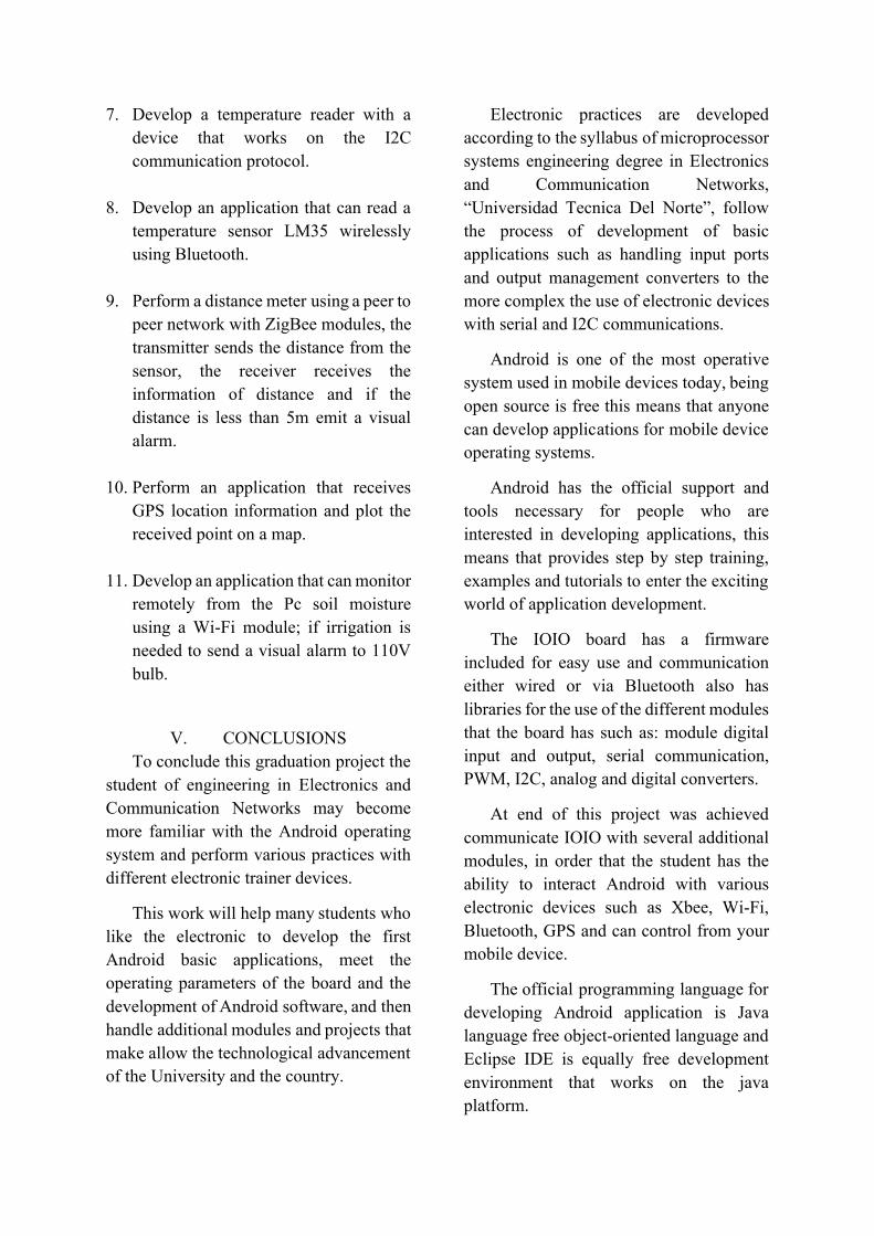
The following diagram shows the
power of the trainer.
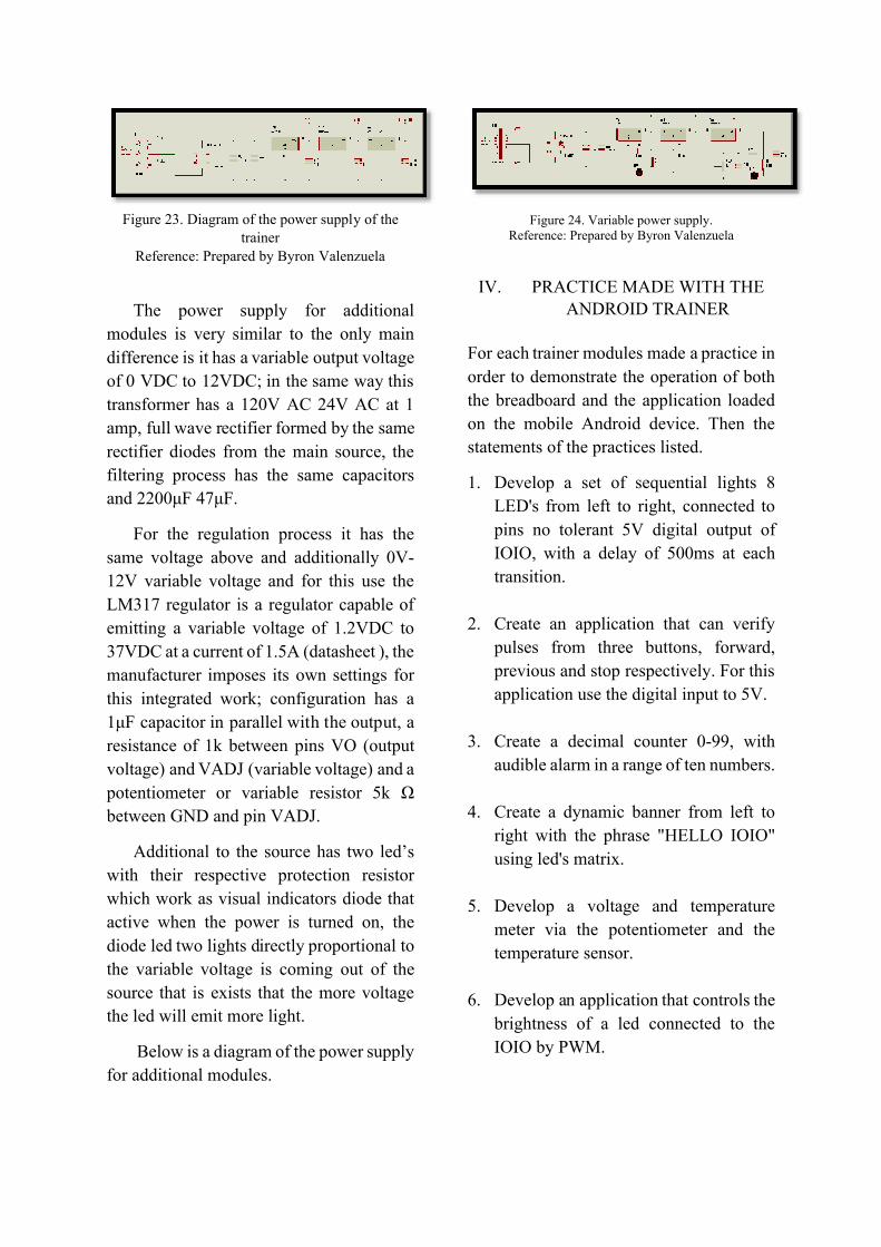
Figure 23. Diagram of the power supply of the
trainer
Reference: Prepared by Byron Valenzuela
The power supply for additional
modules is very similar to the only main
difference is it has a variable output voltage
of 0 VDC to 12VDC; in the same way this
transformer has a 120V AC 24V AC at 1
amp, full wave rectifier formed by the same
rectifier diodes from the main source, the
filtering process has the same capacitors
and 2200μF 47μF.
For the regulation process it has the
same voltage above and additionally 0V-
12V variable voltage and for this use the
LM317 regulator is a regulator capable of
emitting a variable voltage of 1.2VDC to
37VDC at a current of 1.5A (datasheet ), the
manufacturer imposes its own settings for
this integrated work; configuration has a
1μF capacitor in parallel with the output, a
resistance of 1k between pins VO (output
voltage) and VADJ (variable voltage) and a
potentiometer or variable resistor 5k Ω
between GND and pin VADJ.
Additional to the source has two led’s
with their respective protection resistor
which work as visual indicators diode that
active when the power is turned on, the
diode led two lights directly proportional to
the variable voltage is coming out of the
source that is exists that the more voltage
the led will emit more light.
Below is a diagram of the power supply
for additional modules.
Figure 24. Variable power supply. Reference: Prepared by Byron Valenzuela
IV. PRACTICE MADE WITH THE ANDROID TRAINER
For each trainer modules made a practice in
order to demonstrate the operation of both
the breadboard and the application loaded
on the mobile Android device. Then the
statements of the practices listed.
1. Develop a set of sequential lights 8
LED's from left to right, connected to
pins no tolerant 5V digital output of
IOIO, with a delay of 500ms at each
transition.
2. Create an application that can verify
pulses from three buttons, forward,
previous and stop respectively. For this
application use the digital input to 5V.
3. Create a decimal counter 0-99, with
audible alarm in a range of ten numbers.
4. Create a dynamic banner from left to
right with the phrase "HELLO IOIO"
using led's matrix.
5. Develop a voltage and temperature
meter via the potentiometer and the
temperature sensor.
6. Develop an application that controls the
brightness of a led connected to the
IOIO by PWM.
7. Develop a temperature reader with a
device that works on the I2C
communication protocol.
8. Develop an application that can read a
temperature sensor LM35 wirelessly
using Bluetooth.
9. Perform a distance meter using a peer to
peer network with ZigBee modules, the
transmitter sends the distance from the
sensor, the receiver receives the
information of distance and if the
distance is less than 5m emit a visual
alarm.
10. Perform an application that receives
GPS location information and plot the
received point on a map.
11. Develop an application that can monitor
remotely from the Pc soil moisture
using a Wi-Fi module; if irrigation is
needed to send a visual alarm to 110V
bulb.
V. CONCLUSIONS
To conclude this graduation project the
student of engineering in Electronics and
Communication Networks may become
more familiar with the Android operating
system and perform various practices with
different electronic trainer devices.
This work will help many students who
like the electronic to develop the first
Android basic applications, meet the
operating parameters of the board and the
development of Android software, and then
handle additional modules and projects that
make allow the technological advancement
of the University and the country.
Electronic practices are developed
according to the syllabus of microprocessor
systems engineering degree in Electronics
and Communication Networks,
“Universidad Tecnica Del Norte”, follow
the process of development of basic
applications such as handling input ports
and output management converters to the
more complex the use of electronic devices
with serial and I2C communications.
Android is one of the most operative
system used in mobile devices today, being
open source is free this means that anyone
can develop applications for mobile device
operating systems.
Android has the official support and
tools necessary for people who are
interested in developing applications, this
means that provides step by step training,
examples and tutorials to enter the exciting
world of application development.
The IOIO board has a firmware
included for easy use and communication
either wired or via Bluetooth also has
libraries for the use of the different modules
that the board has such as: module digital
input and output, serial communication,
PWM, I2C, analog and digital converters.
At end of this project was achieved
communicate IOIO with several additional
modules, in order that the student has the
ability to interact Android with various
electronic devices such as Xbee, Wi-Fi,
Bluetooth, GPS and can control from your
mobile device.
The official programming language for
developing Android application is Java
language free object-oriented language and
Eclipse IDE is equally free development
environment that works on the java
platform.
At the end of practice with IOIO see
that it is mandatory to include permissions
Bluetooth and Internet use within the
application to develop, you must also attach
the IOIO libraries to access all methods and
libraries electronic control modules in the
same.
The implementation of Android
electronic trainer permit consolidate the
knowledge acquired in the classroom
because the system covers concepts both
networks and electronics.
All applications made in this work are
practices that the student of Engineering in
Electronics and Communication Networks
is in the ability to perform them with prior
knowledge acquired in the classroom.
VI. RECOMMENDATIONS
Before practices is very important to
know the physical and internal structure as
the IOIO has to not cause partial or total
damage within the board, the external
circuit, additional modules that are working
and even the mobile device that is
connected .
Likewise, after the use of various
additional modules the student should be
familiar with the device operating
parameters meet both electrical and
configuration in order to prevent damage to
working modules.
After of to develop the Android IOIO
application, test the performance of the
application by connecting the board to the
mobile via USB cable and Bluetooth and so
check the operation through the two
available connections.
When making practices with the GPS
module, it is advisable to check the
operation of the application in an
environment free of obstacles to avoid
interference when receiving satellite data of
longitude and latitude.
In this work was used as the IOIO
device connected to a terminal Android, the
IOIO OTG version is also able to work as a
host connected to a computer, we
recommend further research and
internships with the IOIO attached.
In addition to the practices presented,
once the student has mastered the subject
can development of electronic applications
with Android; if the application is required
and innovative upload and sell the App
Store obtaining remuneration for the work
done.
REFERENCES Castillo, D. (2012). DISEÑO E
IMPLEMENTACIÓN DE UN SISTEMA DE ALARMA COMUNITARIA A BASE DE MÓDULOS INALÁMBRICOS UTILIZANDO TECNOLOGÍA ZIGBEE. Ibarra.
Clanar Internacional. (s.f.). Internet y redes inalámbricas. Arequipa: Clanar.
Collaguazo, G. (2009). Sistemas Basados en Microprocesadores. Ibarra.
Correia, P. (2002). Guía práctica del GPS. Barcelona: Marcombo.
Creative Commons. (s.f.). Arduino. Obtenido de http://arduino.cc/en/Main/CopyrightNotice
Daniel Benchimol. (2011). Microcontroladores. Buenos Aires: DALAGA S.A.
Digi International, Inc. (2009). XBee®/XBee PRO® RF Modules. New York.
Dignani, J. P. (2011). Análisis del protocolo ZigBee.
GitHub. (2008). Analog Input. Obtenido de https://github.com/ytai/ioio/wiki/Analog-Input
Granadino, C., & Suárez, J. (s.f.). El bus I2C. Chile: Universidad Técnica Federico Santa María.
IOIO for Android. (s.f.). Obtenido de https://www.sparkfun.com/products/10748
Jara, P., & Nazar, P. (s.f.). Estándar IEEE 802.11 X de las WLAN. Buenos Aires: Edutecne.
Monk, S. (2012). Making Android Accessories With IOIO (Vol. I). O'Reilly Media.
Pérez, E. L. (s.f.). Curso de Redes de Microcontroladores PIC (PROTOCOLO SPI). México: Ingeniería en Microcontroladores.
Pérochon, S. (2012). Android Guia de desarollo de aplicaciones para smartphones y tabletas. Barcelona: Ediciones ENI.
Quectel. (2011). L30 Quectel GPS Engine. Shanghai: Quectel.
Quectel. (2013). Quectel L30 Compact GPS Module.
Raúl Esteve Bosch, J. F. (2005). Fundamentos de electrónica digital. Valencia.
RobotFreak. (2008). IOIO-Rover. Obtenido de http://letsmakerobots.com/node/33968
ROVING NETWORKS. (2011). RN-XV Data Sheet. Arizona: ROVING NETWORKS.
sgoliver.net foro. (s.f.). Estructura de un proyecto Android. Obtenido de http://www.sgoliver.net/blog/?p=1278
Ucontrol. (2008). Matrices de LEDs. Ucontrol Elctrónica General Pic´s en particular, 68.
Universidad Politécnica de Valencia. (Abril de 2013). Elementos de un proyecto Android. Obtenido de http://www.androidcurso.com/index.php/recursos-didacticos/tutorialesandroid/31-unidad-1-vision-general-y-entorno-de-desarrollo/148-elementos-de-un-proyecto-android.
Valverde Rebaza, J. C. (2007). El Estándar Inalámbrico ZigBee. Trujillo: Perú.
Edgar A. Maya O. He was born in the Ibarra Imbabura on April 22 1980 Computer Systems Engineer, in the “Universidad Tecnica del Norte” - Ecuador in 2006 currently teaches in the Engineering in Electronics and
Communication Networks at the “Universidad Tecnica del Norte” Ibarra - Ecuador, Master of Communication Networks, Pontifical Catholic University of Ecuador, Quito - Ecuador.
Byron R. Valenzuela M.
He was born in the Ibarra-Ecuador, 20 May 1990 received his primary studies In "La Merced" school and
Secondary education at the
“Teodoro Gomez de la Toree”College where he finished in 2007, obtained the
degree of Bachelor of Science Mathematical Physical Specialization. Currently, he is a graduate of the Engineering Faculty of Applied Science at the “Universidad Tecnica del Norte”.