electronic power conversion - tu delft ocw · electronic power conversion switch mode dc-dc...
TRANSCRIPT
1 Challenge the future 1 Challenge the future
Electronic Power Conversion Switch Mode DC-DC Converters with Isolation

2 Isolated Power Supplies
Switch mode dc-dc converters
Drawbacks of linear power supplies • 50Hz transformer required • transistor absorbs voltage è loss, heat
Frequent requirements: • regulated output • isolation (safety) • multiple outputs
Solutions: • Linear power supplies • Switch mode power supplies

3 Isolated Power Supplies
Switch-mode power supplies
Major advantages: • transistor operates as switch • no 50Hz transformer needed è reduced weight and costs however: • more complex • measures to prevent (conducted) EMI needed • resonant type dc power supplies are not considered here (Ch9)

4 Isolated Power Supplies
Multiple outputs
• one output is regulated by PWM • if needed other output can be post-regulated by linear regulators

5 Isolated Power Supplies
Transformer • Ideal transformer
Faraday’s law
Ampere’s law
0l = Aµ
ℜ ≈
1,2i i
iN i φ
=
= ⋅ℜ∑ 1 1 2 2N i N i φ− = ⋅ℜ
1 1dv Ndtφ= ⋅ 2 2
dv Ndtφ= ⋅
v1N1
=v2N2
1 1 2 2i N i N=Core reluctance

6 Isolated Power Supplies
Transformer • Magnetising inductance
0l = Aµ
ℜ ≠
1 1 2 2N i N i φ− = ⋅ℜ
1 1dv Ndtφ= ⋅
1 21 1 2
1
( ) m mN Nd dv i i L i
dt N dt= ⋅ − = ⋅ℜ
21
mNL =ℜ2
1 21
mNi i iN
= −
Non-zero core reluctance
7 Isolated Power Supplies
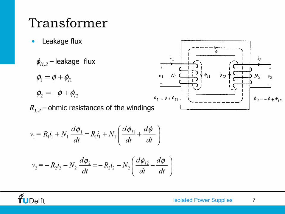
Transformer • Leakage flux
111 1 1 1 1 1 1
ldd dv = R i N R i N
dt dt dtφφ φ⎛ ⎞+ = + +⎜ ⎟⎝ ⎠
222 2 2 2 2 2 2
ldd dv = R i N R i Ndt dt dt
φφ φ⎛ ⎞− − = − − −⎜ ⎟⎝ ⎠
1 1lφ φ φ= +
2 2lφ φ φ= − +
ϕl1,2 – leakage flux
R1,2 – ohmic resistances of the windings
8 Basic Electrical and Magnetic Circuit Concepts
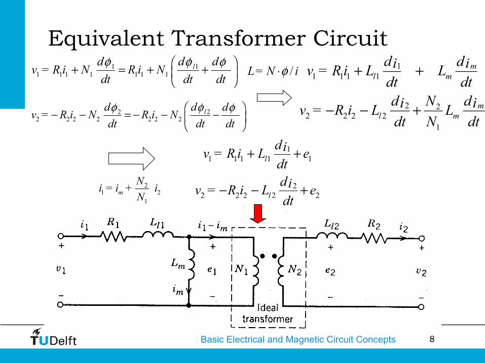
11 1 1 1 1
22 2 2 2 2
l
l
div = R i L edtdiv = R i L edt
+ +
− − +
Equivalent Transformer Circuit
222 2 2 2 2 2 2
ldd dv = R i N R i Ndt dt dt
φφ φ⎛ ⎞− − = − − −⎜ ⎟⎝ ⎠
11 1 1 1
2 22 2 2 2
1
ml m
ml m
d di iv = R i L Ldt dt
Nd di iv = R i L Ldt N dt
+ +
− − +
/L = N iφ⋅
21 2
1m
Ni = i + iN
111 1 1 1 1 1 1
ldd dv = R i N R i N
dt dt dtφφ φ⎛ ⎞+ = + +⎜ ⎟⎝ ⎠

9 Isolated Power Supplies
Transformer representation
• Ll1 and Ll2 are often neglected because they are intentionally small and have a minor effect on the voltage transfer function (they are important for switch selection and snubber design) • Lm is taken into account because it affects circuit operation
1 1 2 2/ /V N V N=
1 1 2 2N i N i=
and
slope
vdt∝ ∫
mi∝mL∝

10 Isolated Power Supplies
• To understand operation of transformer-isolated converters: • replace transformer by equivalent circuit model containing
magnetizing inductance • analyze converter as usual, treating magnetizing inductance as
any other inductor • apply volt-second balance to all converter inductors, including
magnetizing inductance
11 Isolated Power Supplies
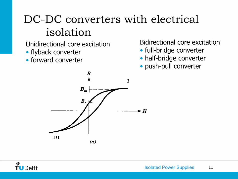
DC-DC converters with electrical isolation
Bidirectional core excitation • full-bridge converter • half-bridge converter • push-pull converter
Unidirectional core excitation • flyback converter • forward converter

12 Isolated Power Supplies
Flyback converter
Magnetic component: • energy storage (coupled inductor) • transformation • isolation
Derived from buck-boost

13 Isolated Power Supplies
I1
Here: N1 I1 + N2 I2 = 0
Flyback converter
,L avV = 0
10
2
( )d on s onNV t - V T - t = 0N
0 2
1d
V N D = V N 1 - D
Steady state:
so:
14 Isolated Power Supplies
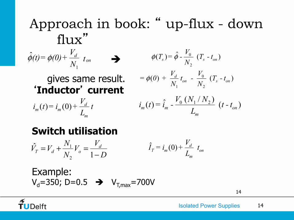
Approach in book: “ up-flux - down flux”
14
1
ˆ don
V(t) = (0) + tNφ φ 0
2
0
1 2
ˆ( ) ( )
( ) ( )
s s on
don s on
VT = - T - tN
V V = 0 + t - T - tN N
φ φ
φ
( ) (0) dm m
m
Vi t = i + tL
0 1 2( / )ˆ( ) ( )m m onm
V N Ni t = i - t - tL
ˆ (0) dT m on
m
VI = i + tL
gives same result. ‘Inductor’ current
Switch utilisation
è
Example: Vd=350; D=0.5 è VT,max=700V
DVV
NNVV d
odT −=+=1
ˆ2
1
15 Isolated Power Supplies
• CCM • Larger transformer • Smaller peak currents
• DCM • Smaller transformer • Larger peak currents
• BCM (boundary condition mode) • “Design of low power power supplies” course – Q3 (control,
EMI, magnetics design, loss calculation) • Flyback converter
• Low part count (cheap) • High transistor voltage stress
16 Isolated Power Supplies
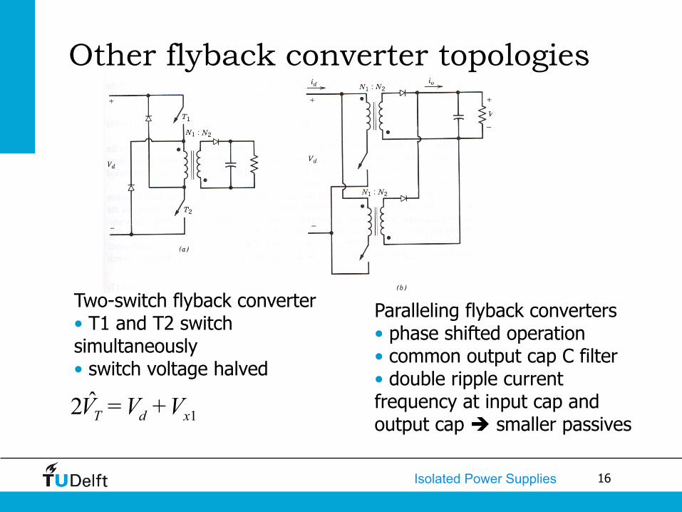
Other flyback converter topologies
1ˆ2 T d xV = V + V
Two-switch flyback converter • T1 and T2 switch simultaneously • switch voltage halved
Paralleling flyback converters • phase shifted operation • common output cap C filter • double ripple current frequency at input cap and output cap è smaller passives

17 Isolated Power Supplies
Forward converter
20
1L d
Nv = V - VN
0Lv = -V
(0 < t < ton)
( ton < t < Ts)
Demagnetisation winding function: remove energy stored in Lm
,L avv = 0 20 0
1
( )d on s onN V V t - V T - t = 0N
⎛ ⎞−⎜ ⎟
⎝ ⎠0 2
1d
V N = DV Nè è
,L avv = 00 ?d
VV
è
switch off, D2 on
switch on, D1 on
18 Isolated Power Supplies
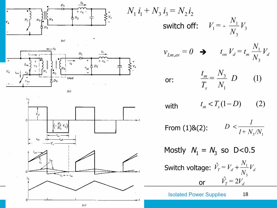
Mostly N1 = N3 so D<0.5
ˆ 2T dV = V
D
1
3T̂ d d
NV = V V N
+
11 3
3
NV = - VN
,Lm avv = 0 1
3on d m d
Nt V = t VN
switch off:
3
1
(1)m
s
t N = DT N
(1 ) (2)m st T D< −
3 1
1D 1 + N /N
<
with
From (1)&(2):
è
or:
Switch voltage:
or
1 1 3 3 2 2N i + N i = N i

19 Isolated Power Supplies
Other forward converter topologies
Two-switch forward converter • T1 and T2 switch simultaneously • switch voltage halved • no demagnetisation winding needed
Paralleling forward converters • phase shifted operation • single LC filter • double ripple current frequency at input cap and LC filter è smaller passives
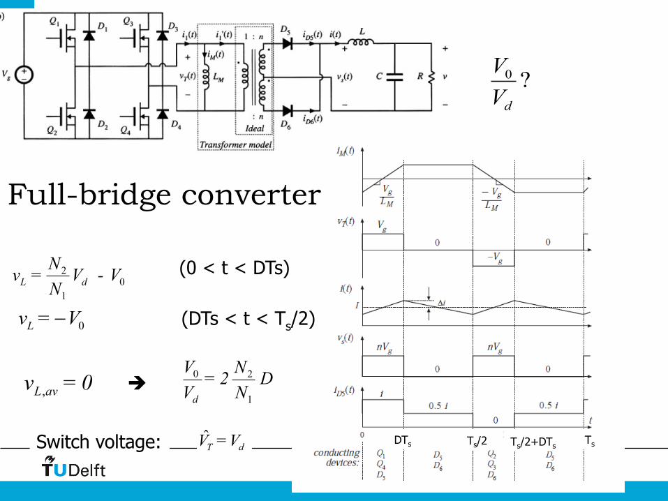
20 Isolated Power Supplies
20
1L d
Nv = V - VN
0Lv = V−
,L avv = 0 0 2
1d
V N = 2 DV N
(0 < t < DTs)
(DTs < t < Ts/2)
è
0 ?d
VV
T̂ dV = V Switch voltage:
Full-bridge converter
Ts/2 Ts Ts/2+DTs DTs
21 Isolated Power Supplies
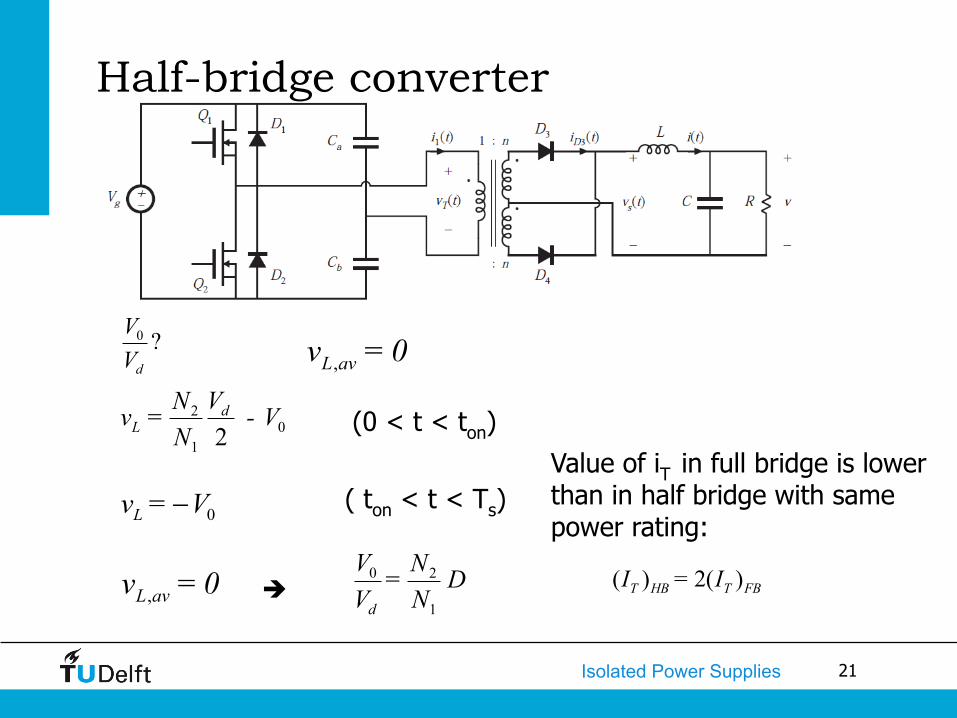
Half-bridge converter
20
1 2d
LVNv = - V
N
0Lv = V−
,L avv = 0 0 2
1d
V N = DV N
(0 < t < ton)
( ton < t < Ts)
è
,L avv = 00 ?d
VV
Value of iT in full bridge is lower than in half bridge with same power rating:
( ) 2( )T HB T FBI = I

22 Isolated Power Supplies
Push-pull converter
20
1L d
Nv = V - VN
0Lv = V
,L avv = 0 0 2
1d
V N = 2 DV N
(0 < t < ton)
( ton < t < Ts)
è
(0 < D < 0.5)
,L avv = 00 ?d
VV
ˆ 2T dV = V Switch voltage: • risk of transformer saturation

23 Isolated Power Supplies
DC-DC converters with electrical isolation
Bidirectional core excitation (ΔBp_p=2Bm)
• push-pull converter • half-bridge converter • full-bridge converter
Unidirectional core excitation (ΔBp_p=Bm-Br) • flyback converter • forward converter

24 Isolated Power Supplies
Transformer core selection
])B( [ f k =density loss Core bas maxΔ
max1
( )c s
VB = (at D = 0.5)4 N A f
Δ

25 Isolated Power Supplies
PWM-control of dc-dc converters with isolation

26 Isolated Power Supplies
3. A forward converter shown below is operating in a continuous conduction mode. The demagnetising winding is chosen to be N3=N1. All components can be assumed to be ideal, except for the presence of transformer magnetising inductance. The converter specifications are: • Vd=48V±10% • Vo=5V
• fs=100kHz • Pload=15-50W a) (10) Calculate the transformer turns ratio N2/N1 is this turns ratio is desired to be as small as possible.
b) (10) Calculate the minimum value of the filter inductance. c) (5) Calculate the voltage rating of the switch in terms of the input voltage Vd.

27 Isolated Power Supplies
Design a flyback converter operating in the discontinuous conduction mode with the following specifications: • Input voltage 300V≤Vd≤400V (nominal value 400V) • Output power 0V≤Po≤50W (nominal value 50W) • Output voltage 20V≤Vo≤30W (nominal value 27V) • Switching frequency fs=50kHz • Peak –to-peak voltage ripple ΔV0p_p=20mV. a) (15) Select the transformer turn ratio N2/N1, the magnetising inductance Lm and the output capacitance C. You may assume that the maximum duty cycle value is 0.5. The voltage drop across the diode when it is in on-state is 1V. b) Sketch the waveforms and calculate RMS and DC values of the transistor and output diode current at the nominal operating point. c) Sketch the waveforms and calculate the maximum voltages across the transistor and output diode.

28 Isolated Power Supplies
In the figure below two parallel forward converters are shown. Draw the input current id and iL waveforms if each converter is operating at a duty ratio of 0.3 in a continuous-conduction mode. Compare these two waveforms with those if a single forward converter (with twice the power rating but with the same value of the output filter inductance as in double forward) is used.

29 Isolated Power Supplies
Image credits
• All uncredited diagrams are from the book “Power Electronics: Converters, Applications, and Design” by N. Mohan, T.M. Undeland and W.P. Robbins.
• All other uncredited images are from research done at the EWI faculty.