electronic circuit breaker 787-1668(/xxxx-xxxx)epsitron® electronic circuit breaker...
TRANSCRIPT

Pos: 2 /D okumentati on allgemein/Ei nband/Ei nband H andbuch - Deckbl att ohne Variantenfel d (Standar d) @ 9\mod_1285229289866_0.docx @ 64941 @ @ 1
Manual
EPSITRON® Electronic Circuit Breaker
787-1668(/xxxx-xxxx) 24 VDC, 8 × 2 … 10 A
Version 1.1.0 Pos: 3 /Alle Serien (Allgemeine M odul e)/Hinweise zur Dokumentation/Impressum für Standardhandbücher - allg. Angaben, Anschriften, Tel efonnummer n und E-Mail-Adressen @ 3\mod_1219151118203_21.docx @ 21060 @ @ 1
2 EPSITRON® 787-1668 Electronic Circuit Breaker
Manual Version 1.1.0
© 2014 by WAGO Kontakttechnik GmbH & Co. KG All rights reserved.
WAGO Kontakttechnik GmbH & Co. KG
Hansastraße 27 D-32423 Minden
Phone: +49 (0) 571/8 87 – 0 Fax: +49 (0) 571/8 87 – 1 69
E-Mail: [email protected]
Web: http://www.wago.com
Technical Support
Phone: +49 (0) 571/8 87 – 5 55 Fax: +49 (0) 571/8 87 – 85 55
E-Mail: [email protected]
Every conceivable measure has been taken to ensure the accuracy and completeness of this documentation. However, as errors can never be fully excluded, we always appreciate any information or suggestions for improving the documentation.
E-Mail: [email protected]
We wish to point out that the software and hardware terms as well as the trademarks of companies used and/or mentioned in the present manual are generally protected by trademark or patent.
=== Ende der Liste für Textmar ke Ei nband_vorne ===

EPSITRON® Table of Contents 3 787-1668 Electronic Circuit Breaker
Manual Version 1.1.0
Pos: 5 /D okumentati on allgemein/Verzeichnisse/Inhaltsverzeichnis - Ü berschrif t oG und Verzei chnis @ 3\mod_1219151230875_21.docx @ 21063 @ @ 1
Table of Contents Table of Contents ................................................................................................... 3
1 Notes about this Documentation ................................................................. 5 1.1 Validity of this Documentation ................................................................. 5 1.2 Copyright ................................................................................................... 5 1.3 Symbols ..................................................................................................... 6 1.4 Number Notation ....................................................................................... 8 1.5 Font Conventions ...................................................................................... 8
2 Important Notes ........................................................................................... 9 2.1 Legal Bases ............................................................................................... 9 2.1.1 Subject to Changes ............................................................................... 9 2.1.2 Personnel Qualifications ....................................................................... 9 2.1.3 Use of the 787 Series in Compliance with Underlying Provisions ...... 9 2.1.4 Technical Condition of Specified Devices ......................................... 10 2.2 Safety Advice (Precautions) .................................................................... 11
3 Device Description ..................................................................................... 13 3.1 View ........................................................................................................ 14 3.2 Connectors ............................................................................................... 15 3.2.1 Power supply ...................................................................................... 15 3.2.2 Fuse-Protected Outputs ...................................................................... 16 3.2.3 Control and Signaling Contacts .......................................................... 16 3.3 Display Elements .................................................................................... 17 3.4 Operating Elements ................................................................................. 18 3.4.1 Buttons ................................................................................................ 18 3.4.2 Rotary Switch ..................................................................................... 19 3.5 Technical Data ........................................................................................ 20 3.5.1 Device Data ........................................................................................ 20 3.5.2 Technical Data for "Input" ................................................................. 21 3.5.3 Technical Data for "Output" ............................................................... 22 3.5.4 Technical Data for "Ambient conditions" .......................................... 23 3.5.5 Technical Data for "Signaling" .......................................................... 23 3.6 Approvals ................................................................................................ 24 3.7 Standards and Guidelines ........................................................................ 25
4 Mounting ..................................................................................................... 26 4.1 Mounting ................................................................................................. 26 4.2 Mounting the Device on the DIN 35 Rail ............................................... 26 4.3 Removing the Device from the DIN 35 Rail .......................................... 27
5 Connect Devices ......................................................................................... 28 5.1 Connection Example ............................................................................... 28
6 Function Description ................................................................................. 29 6.1 Undervoltage and Overvoltage Detection ............................................... 29 6.2 Trip Curves .............................................................................................. 29 6.2.1 Trip Curve for the 10 A Circuit Breaker 787-1668 ............................ 29 6.2.2 Trip Curve for the 6 A Circuit Breaker 787-1668/0106-0000 ........... 30
4 Table of Contents EPSITRON® 787-1668 Electronic Circuit Breaker
Manual Version 1.1.0
6.2.3 Trip Curve for the 6 A Circuit Breaker with Active Current Limitation 787-1668/0006-1000 .......................................................................... 30
6.2.3.1 Response of the Electronic Circuit Breaker with Active Current Limitation ...................................................................................... 31
6.2.3.1.1 Response 1: Over-current present that is greater than Threshold 3 ................................................................................................. 32
6.2.3.1.2 Response 2: Over-current present that is greater than Threshold 1, but less than Threshold 2 ...................................................... 32
6.2.3.1.3 Response 3: Over-current present that is greater than the nominal current, but less than Threshold 1 ............................... 32
6.2.3.2 Selective immediate deactivation .................................................. 32 6.3 Activating Capacitive Loads ................................................................... 33 6.3.1 Reference Values for 787-1668 and 787-1668/0106-0000 ................ 33 6.3.2 Reference Values for 787-1668/0006-1000 ....................................... 33 6.4 Operating Statuses, Signaling, Reactions ................................................ 34 6.5 ON Delay for Specific Channels ............................................................. 36 6.6 Control Input S1 ...................................................................................... 37 6.6.1 Re-activating Tripped Channels ......................................................... 37 6.6.2 Specific Activation and De-activation of Non-Tripped Output
Channels ............................................................................................. 38 6.7 Signal Output S2 ..................................................................................... 42 6.8 Functioning of Communication between Control Input S1 and Signal
Output S2 ................................................................................................ 44 6.9 Signal Output S3 ..................................................................................... 45
List of Figures ...................................................................................................... 46
List of Tables ........................................................................................................ 47
=== Ende der Liste für Textmar ke Verzeichnis_vor ne ===
EPSITRON® Notes about this Documentation 5 787-1668 Electronic Circuit Breaker
Manual Version 1.1.0
Pos: 7 /Alle Serien (Allgemeine M odul e)/Überschriften für all e Serien/Hi nweis zur Dokumentation/Hinweise zur D okumentation - Ü berschrift 1 @ 4\mod_1237987661750_21.docx @ 29029 @ 1 @ 1
1 Notes about this Documentation Pos: 8 /Alle Serien (Allgemeine M odul e)/Hinweise zur Dokumentation/Hi nweise/Hi nweis : D okumentation aufbewahr en @ 4\mod_1237987339812_21.docx @ 29026 @ @ 1
Keep this documentation! The operating instructions are part of the product and shall be kept for the entire lifetime of the device. They shall be transferred to each subsequent owner or user of the device. Care must also be taken to ensure that any supplement to these instructions are included, if applicable.
Pos: 9 /Alle Serien (Allgemeine M odul e)/Überschriften für all e Serien/Hi nweis zur Dokumentation/Gültig keitsber eich - Überschrift 2 @ 12\mod_1338912448776_21.docx @ 96469 @ 2 @ 1
1.1 Validity of this Documentation Pos: 10 /Serie 787 (EPSITRON)/Hi nweise zur D okumentati on/Gültig keitsbereich/Gül tigkeit D okumentati on El ektr onischer Schutzschalter 787-16xx @ 13\mod_1342442188427_21.docx @ 100350 @ @ 1
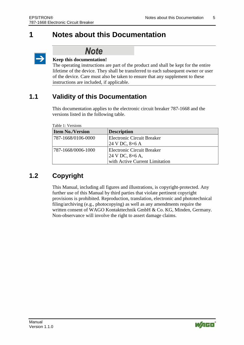
This documentation applies to the electronic circuit breaker 787-1668 and the versions listed in the following table.
Pos: 11 /Serie 787 (EPSITRON)/Hi nweise zur D okumentati on/Variantenlis ten/Vari antenliste Elektronischer Schutzschalter 787-1668 @ 17\mod_1385394669703_21.docx @ 138295 @ @ 1
Table 1: Versions Item No./Version Description 787-1668/0106-0000 Electronic Circuit Breaker
24 V DC, 8×6 A 787-1668/0006-1000 Electronic Circuit Breaker
24 V DC, 8×6 A, with Active Current Limitation
Pos: 12.1 /All e Seri en ( Allgemei ne Module)/Hi nweise zur D okumentati on/Urheberschutz ausführlich @ 4\mod_1235565145234_21.docx @ 27691 @ 2 @ 1
1.2 Copyright This Manual, including all figures and illustrations, is copyright-protected. Any further use of this Manual by third parties that violate pertinent copyright provisions is prohibited. Reproduction, translation, electronic and phototechnical filing/archiving (e.g., photocopying) as well as any amendments require the written consent of WAGO Kontakttechnik GmbH & Co. KG, Minden, Germany. Non-observance will involve the right to assert damage claims.
Pos: 12.2 /Dokumentation allgemei n/Glieder ungselemente/---Seitenwechsel--- @ 3\mod_1221108045078_0.docx @ 21810 @ @ 1
6 Notes about this Documentation EPSITRON® 787-1668 Electronic Circuit Breaker
Manual Version 1.1.0
Pos: 12.3 /All e Seri en ( Allgemei ne Module)/Ü berschriften für alle Serien/Hinweis zur D okumentati on/Symbole - Ü berschrif t 2 @ 13\mod_1351068042408_21.docx @ 105270 @ 2 @ 1
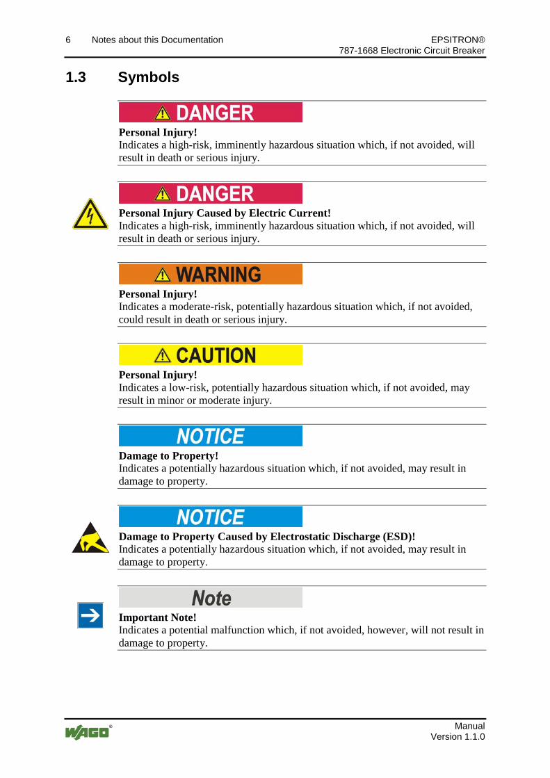
1.3 Symbols Pos: 12.4.1 /All e Serien ( Allgemei ne Module)/Wichtige Erläuterungen/Sicherheits- und sons tige Hinweise/Gefahr/Gefahr: _War nung vor Personenschäden allgemei n_ - Erl äuter ung @ 13\mod_1343309450020_21.docx @ 101029 @ @ 1
Personal Injury! Indicates a high-risk, imminently hazardous situation which, if not avoided, will result in death or serious injury.
Pos: 12.4.2 /All e Serien ( Allgemei ne Module)/Wichtige Erläuterungen/Sicherheits- und sons tige Hinweise/Gefahr/Gefahr: _War nung vor Personenschäden durch elektrischen Strom_ - Erläuterung @ 13\mod_1343309694914_21.docx @ 101030 @ @ 1
Personal Injury Caused by Electric Current! Indicates a high-risk, imminently hazardous situation which, if not avoided, will result in death or serious injury.
Pos: 12.4.3 /All e Serien ( Allgemei ne Module)/Wichtige Erläuterungen/Sicherheits- und sons tige Hinweise/Warnung/Warnung: _Warnung vor Personenschäden allgemei n_ - Erläuterung @ 13\mod_1343309877041_21.docx @ 101035 @ @ 1
Personal Injury! Indicates a moderate-risk, potentially hazardous situation which, if not avoided, could result in death or serious injury.
Pos: 12.4.4 /All e Serien ( Allgemei ne Module)/Wichtige Erläuterungen/Sicherheits- und sons tige Hinweise/Vorsicht/Vorsicht: _War nung vor Personenschäden allgemein_ - Erläuterung @ 13\mod_1343310028762_21.docx @ 101038 @ @ 1
Personal Injury! Indicates a low-risk, potentially hazardous situation which, if not avoided, may result in minor or moderate injury.
Pos: 12.4.5 /All e Serien ( Allgemei ne Module)/Wichtige Erläuterungen/Sicherheits- und sons tige Hinweise/Achtung/Achtung: _War nung vor Sachschäden allgemein_ - Erläuterung @ 13\mod_1343310134623_21.docx @ 101041 @ @ 1
Damage to Property! Indicates a potentially hazardous situation which, if not avoided, may result in damage to property.
Pos: 12.4.6 /All e Serien ( Allgemei ne Module)/Wichtige Erläuterungen/Sicherheits- und sons tige Hinweise/Achtung/Achtung: _War nung vor Sachschäden durch elektr ostatische Aufladung_ - Erläuterung @ 13\mod_1343310227702_21.docx @ 101044 @ @ 1
Damage to Property Caused by Electrostatic Discharge (ESD)! Indicates a potentially hazardous situation which, if not avoided, may result in damage to property.
Pos: 12.4.7 /All e Serien ( Allgemei ne Module)/Wichtige Erläuterungen/Sicherheits- und sons tige Hinweise/Hi nweis /Hinweis: _Wichtiger Hi nweis allgemein_ - Erläuterung @ 13\mod_1343310326906_21.docx @ 101047 @ @ 1
Important Note! Indicates a potential malfunction which, if not avoided, however, will not result in damage to property.
Pos: 12.4.8 /All e Serien ( Allgemei ne Module)/Wichtige Erläuterungen/Sicherheits- und sons tige Hinweise/Infor mation/Infor mation: _Weiter e Infor mation allgemei n_ - Erl äuter ung @ 13\mod_1343310439814_21.docx @ 101051 @ @ 1

EPSITRON® Notes about this Documentation 7 787-1668 Electronic Circuit Breaker
Manual Version 1.1.0
Additional Information: Refers to additional information which is not an integral part of this documentation (e.g., the Internet).
Pos: 12.5 /Dokumentation allgemei n/Glieder ungselemente/---Seitenwechsel--- @ 3\mod_1221108045078_0.docx @ 21810 @ @ 1

8 Notes about this Documentation EPSITRON® 787-1668 Electronic Circuit Breaker
Manual Version 1.1.0
Pos: 12.6 /All e Seri en ( Allgemei ne Module)/Hi nweise zur D okumentati on/Zahlensysteme @ 3\mod_1221059454015_21.docx @ 21711 @ 2 @ 1
1.4 Number Notation Table 2: Number notation Number code Example Note Decimal 100 Normal notation Hexadecimal 0x64 C notation Binary '100'
'0110.0100' In quotation marks, nibble separated with dots (.)
Pos: 12.7 /All e Seri en ( Allgemei ne Module)/Hi nweise zur D okumentati on/Schriftkonventi onen @ 3\mod_1221059521437_21.docx @ 21714 @ 2 @ 1
1.5 Font Conventions Table 3: Font conventions Font type Indicates italic Names of paths and data files are marked in italic-type.
e.g.: C:\Programme\WAGO-I/O-CHECK Menu Menu items are marked in bold letters.
e.g.: Save > A greater-than sign between two names means the selection of a
menu item from a menu. e.g.: File > New
Input Designation of input or optional fields are marked in bold letters, e.g.: Start of measurement range
“Value” Input or selective values are marked in inverted commas. e.g.: Enter the value “4 mA” under Start of measurement range.
[Button] Pushbuttons in dialog boxes are marked with bold letters in square brackets. e.g.: [Input]
[Key] Keys are marked with bold letters in square brackets. e.g.: [F5]
Pos: 13 /D okumentation allgemei n/Glieder ungselemente/---Seitenwechsel--- @ 3\mod_1221108045078_0.docx @ 21810 @ @ 1

EPSITRON® Important Notes 9 787-1668 Electronic Circuit Breaker
Manual Version 1.1.0
Pos: 14 /All e Seri en (Allgemei ne Module)/Ü berschrif ten für alle Serien/Wichtige Erläuterungen/Wichtige Erläuter ungen - Überschrift 1 @ 4\mod_1241428899156_21.docx @ 32170 @ 1 @ 1
2 Important Notes Pos: 15.1 /All e Seri en ( Allgemei ne Module)/Wichtige Erläuterungen/Einl eitung Wichtige Erläuterungen @ 3\mod_1221059818031_21.docx @ 21717 @ @ 1
This section includes an overall summary of the most important safety requirements and notes that are mentioned in each individual section. To protect your health and prevent damage to devices as well, it is imperative to read and carefully follow the safety guidelines.
Pos: 15.2 /All e Seri en ( Allgemei ne Module)/Ü berschriften für alle Serien/Wichtige Erläuter ungen/Rechtliche Gr undl agen - Ü berschrift 2 @ 3\mod_1221060626343_21.docx @ 21726 @ 2 @ 1
2.1 Legal Bases Pos: 15.3 /All e Seri en ( Allgemei ne Module)/Wichtige Erläuterungen/Änderungsvor behalt - Ü berschrift 3 und Inhalt @ 3\mod_1221060036484_21.docx @ 21720 @ 3 @ 1
2.1.1 Subject to Changes
WAGO Kontakttechnik GmbH & Co. KG reserves the right to provide for any alterations or modifications that serve to increase the efficiency of technical progress. WAGO Kontakttechnik GmbH & Co. KG owns all rights arising from the granting of patents or from the legal protection of utility patents. Third-party products are always mentioned without any reference to patent rights. Thus, the existence of such rights cannot be excluded.
Pos: 15.4 /Serie 787 (EPSITRON)/Wichtige Erläuterungen/Personalqualifi kati on 787- xxxx @ 11\mod_1317113061338_21.docx @ 79692 @ 3 @ 1
2.1.2 Personnel Qualifications
All sequences implemented on 787 Series devices may only be carried out by electrical specialists with sufficient knowledge in automation. The specialists must be familiar with the current norms and guidelines for the devices and automated environments.
Pos: 15.5 /Serie 787 (EPSITRON)/Wichtige Erläuterungen/Besti mmungsgemäße Ver wendung 787- xxxx @ 11\mod_1317113060572_21.docx @ 79688 @ 3 @ 1
2.1.3 Use of the 787 Series in Compliance with Underlying Provisions
The EPSITRON® 787 Series power supply system provides direct current to electric or electronic devices, such as industrial control systems or display, communication and measuring devices.
The devices have been developed for use in an environment that meets the IP20 protection class criteria. Protection against finger injury and solid impurities up to 12.5 mm diameter is assured; protection against water damage is not ensured. Unless otherwise specified, operation of the components in wet and dusty environments is prohibited.
The devices are designed for installation in an enclosure. Under no circumstances may they be used in control systems for planes or nuclear facilities, as any malfunction in these applications could result in severe injuries or risk of death.
Pos: 15.6 /Dokumentation allgemei n/Glieder ungselemente/---Seitenwechsel--- @ 3\mod_1221108045078_0.docx @ 21810 @ @ 1

10 Important Notes EPSITRON® 787-1668 Electronic Circuit Breaker
Manual Version 1.1.0
Pos: 15.7 /All e Seri en ( Allgemei ne Module)/Wichtige Erläuterungen/Technischer Zustand der Geräte - Überschrift 3 und Inhalt @ 3\mod_1221060446109_21.docx @ 21723 @ 3 @ 1
2.1.4 Technical Condition of Specified Devices
The components to be supplied Ex Works, are equipped with hardware and software configurations, which meet the individual application requirements. WAGO Kontakttechnik GmbH & Co. KG will be exempted from any liability in case of changes in hardware or software as well as to non-compliant usage of components.
Please send your request for modified and new hardware or software configurations directly to WAGO Kontakttechnik GmbH & Co. KG.
Pos: 15.8 /Dokumentation allgemei n/Glieder ungselemente/---Seitenwechsel--- @ 3\mod_1221108045078_0.docx @ 21810 @ @ 1

EPSITRON® Important Notes 11 787-1668 Electronic Circuit Breaker
Manual Version 1.1.0
Pos: 15.9 /All e Seri en ( Allgemei ne Module)/Ü berschriften für alle Serien/Wichtige Erläuter ungen/Sicherheitshinweise - Überschrift 2 @ 6\mod_1260180299987_21.docx @ 46724 @ 2 @ 1
2.2 Safety Advice (Precautions) Pos: 15.10 /Alle Serien (Allgemeine M odul e)/Wichtige Erläuterungen/Sicherheits- und sonstige Hinweise/Ei nlei tung Sicherheitshinweise Har dwar e @ 6\mod_1260180170493_21.docx @ 46720 @ @ 1
For installing and operating purposes of the relevant device to your system the following safety precautions shall be observed:
Pos: 15.11 /Alle Serien (Allgemeine M odul e)/Wichtige Erläuterungen/Sicherheits- und sonstige Hinweise/Gefahr/Gefahr: Nicht an Geräten unter Spannung ar bei ten! @ 6\mod_1260180365327_21.docx @ 46727 @ @ 1
Do not work on components while energized! All power sources to the device shall be switched off prior to performing any installation, repair or maintenance work.
Pos: 15.12 /Serie 787 ( EPSITR ON)/Wichtige Erläuterungen/Sicherheits- und sonstige Hinweise/Gefahr/Gefahr: Ei nbau 787- xxxx nur i n Gehäusen, Schr änken oder elektrischen Betri ebsr äumen! @ 11\mod_1317113246230_21.docx @ 79696 @ @ 1
Installation only in appropriate housings, cabinets or in electrical operation rooms! Always install devices of the 787 Series in enclosures, cabinets or electrical equipment rooms which can be closed and locked. Ensure that access to this equipment/these rooms is possible only by authorized specialists with the appropriate key or tools.
Pos: 15.13 /Serie 787 ( EPSITR ON)/Wichtige Erläuterungen/Sicherheits- und sonstige Hinweise/Gefahr/Gefahr: Geräte nicht in Steuer ungsanl agen ver wenden! @ 13\mod_1346400862576_21.docx @ 102180 @ @ 1
Do not use these devices in control systems for planes, trains or nuclear facilities! Never use these devices in control systems for planes, trains or nuclear facilities, as any malfunction in these applications can result in severe injuries or risk of death!
Pos: 15.14 /Alle Serien (Allgemeine M odul e)/Wichtige Erläuterungen/Sicherheits- und sonstige Hinweise/Gefahr/Gefahr: Unfall verhütungsvorschriften beachten! @ 6\mod_1260180657000_21.docx @ 46735 @ @ 1
Pos: 15.15 /Alle Serien (Allgemeine M odul e)/Wichtige Erläuterungen/Sicherheits- und sonstige Hinweise/Gefahr/Gefahr: Auf nor mgerechten Anschl uss achten! @ 6\mod_1260180753479_21.docx @ 46739 @ @ 1 Pos : 15.16 /Serie 787 ( EPSITR ON)/Wichtige Erläuterungen/Sicherheits- und sonstige Hinweise/Achtung/Achtung: Versorgungsspannung bei defektem Ger ät abschalten! @ 13\mod_1346401405605_21.docx @ 102187 @ @ 1
Switch off power supply to defective device! Switch off power supply to the device immediately if the device malfunctions or is damaged! Control systems connected to the device may also be damaged! Return the defective device directly to WAGO.
Pos: 15.17 /Serie 787 ( EPSITR ON)/Wichtige Erläuterungen/Sicherheits- und sonstige Hinweise/Achtung/Achtung: Federleis ten nicht unter Last stecken oder ziehen! @ 18\mod_1392900217463_21.docx @ 145941 @ @ 1
Do not plug in or disconnect the female connector while a load is applied! Only plug in or disconnect the female connectors when the device is not live! Failure to observe this can result in damage to the contacts due to arcing!
Pos: 15.18 /Serie 787 ( EPSITR ON)/Wichtige Erläuterungen/Sicherheits- und sonstige Hinweise/Achtung/Achtung: Federleis ten bis zum Anschl ag in di e Stiftl eisten stecken! @ 18\mod_1392902889021_21.docx @ 145944 @ @ 1
Plug the female connectors all the way into the male connectors! Always plug the female connectors all the way in to the male connectors. This ensures proper contact at all times.
Pos: 15.19 /Serie 787 ( EPSITR ON)/Wichtige Erläuterungen/Sicherheits- und sonstige Hinweise/Achtung/Achtung: Fr eischwi ngende Leiter enden durch ei ne geeignete Zugentlas tung abfangen! @ 18\mod_1392904262758_21.docx @ 146008 @ @ 1

12 Important Notes EPSITRON® 787-1668 Electronic Circuit Breaker
Manual Version 1.1.0
Attach the free ends of the conductors using a strain relief device! Provide appropriate strain relief means to attach and cap any free ends of the conductors. Female connectors can be pulled out of the male connectors by high vibration levels or shock impacts.
Pos: 15.20 /Alle Serien (Allgemeine M odul e)/Wichtige Erläuterungen/Sicherheits- und sonstige Hinweise/Achtung/Achtung: Geräte vor kriechenden und isoli erenden Stoffen schützen! @ 6\mod_1260181036216_21.docx @ 46747 @ @ 1
Protect the components against materials having seeping and insulating properties! The components are not resistant to materials having seeping and insulating properties such as: aerosols, silicones and triglycerides (found in some hand creams). If you cannot exclude that such materials will appear in the component environment, then install the components in an enclosure being resistant to the above-mentioned materials. Clean tools and materials are imperative for handling devices/modules.
Pos: 15.21 /Alle Serien (Allgemeine M odul e)/Wichtige Erläuterungen/Sicherheits- und sonstige Hinweise/Achtung/Achtung: R einigung nur mit zul ässigen M aterialien! @ 6\mod_1260181203293_21.docx @ 46751 @ @ 1
Cleaning only with permitted materials! Clean soiled contacts using oil-free compressed air or with ethyl alcohol and leather cloths.
Pos: 15.22 /Alle Serien (Allgemeine M odul e)/Wichtige Erläuterungen/Sicherheits- und sonstige Hinweise/Achtung/Achtung: Kei n Kontaktspray verwenden! @ 6\mod_1260181290808_21.docx @ 46755 @ @ 1
Do not use any contact spray! Do not use any contact spray. The spray may impair contact area functionality in connection with contamination.
Pos: 15.23 /Alle Serien (Allgemeine M odul e)/Wichtige Erläuterungen/Sicherheits- und sonstige Hinweise/Achtung/Achtung: Ver pol ung ver mei den! @ 6\mod_1260184045744_21.docx @ 46767 @ @ 1
Do not reverse the polarity of connection lines! Avoid reverse polarity of data and power supply lines, as this may damage the devices involved.
Pos: 15.24 /Alle Serien (Allgemeine M odul e)/Wichtige Erläuterungen/Sicherheits- und sonstige Hinweise/Achtung/Achtung: El ektr ostatische Entladung vermei den! @ 6\mod_1260181364729_21.docx @ 46759 @ @ 1
Avoid electrostatic discharge! The devices are equipped with electronic components that you may destroy by electrostatic discharge when you touch. Pay attention while handling the devices to good grounding of the environment (persons, job and packing).
Pos: 16 /D okumentation allgemei n/Glieder ungselemente/---Seitenwechsel--- @ 3\mod_1221108045078_0.docx @ 21810 @ @ 1

EPSITRON® Device Description 13 787-1668 Electronic Circuit Breaker
Manual Version 1.1.0
Pos: 17 /All e Seri en (Allgemei ne Module)/Ü berschrif ten für alle Serien/Gerätebeschreibung/Gerätebeschr eibung - Überschrift 1 @ 3\mod_1233756084656_21.docx @ 27096 @ 1 @ 1
3 Device Description Pos: 18.1 /Serie 787 (EPSITRON)/Ger ätebeschrei bung/Beschr eibung/Anwendung/Anwendung 787-1668 @ 12\mod_1342431638280_21.docx @ 100295 @ @ 1
The 787-1668 electronic circuit breaker reliably protects up to 8 load circuits against short circuiting and overloading. The 24 VDC input voltage is distributed among 8 output channels, each of which can be provided with separate fuse protection.
Table 4: Fuse Protection of Output Channels Variant Fuse protection for each output
channel (can be set) 787-1668 2 A, 3 A, 4 A, 6 A, 8 A, 10 A 787-1668/0106-0000 1 A, 2 A, 3 A, 4 A, 5 A, 6 A 787-1668/0006-1000 0,5 A, 1 A, 2 A, 3 A, 4 A, 6 A
(with active current limitation) The electronics can accommodate brief current peaks.
Pos: 18.2 /Serie 787 (EPSITRON)/Ger ätebeschrei bung/Beschr eibung/Funkti on/Funktion 787-1668: Drehschal ter @ 12\mod_1342432084601_21.docx @ 100304 @ @ 1
There are 8 rotary switches on the device which can be used to set the nominal current for each of the individual output channels.
Pos: 18.3 /Serie 787 (EPSITRON)/Ger ätebeschrei bung/Beschr eibung/LED-Anzeig e/LED-Anzeige 787- 16xx @ 12\mod_1342431879376_21.docx @ 100301 @ @ 1
The current status of the output channel is indicated by a multi-colored LED. Pos: 18.4 /Serie 787 (EPSITRON)/Ger ätebeschrei bung/Beschr eibung/Funkti on/Funktion 787-16xx: Kurzschluss und Ü berlast @ 13\mod_1342432174185_21.docx @ 100307 @ @ 1
In the event of a short circuit or overloading, the individual output channel is de-energized after a defined trip time.
Pos: 18.5 /Serie 787 (EPSITRON)/Ger ätebeschrei bung/Beschr eibung/Anwendung/Hinweise/Hinweis: Ther mische Entspannung abwarten 787- 16xx @ 12\mod_1342431732847_21.docx @ 100298 @ @ 1
Wait for temperature to return to normal! If an output channel has been de-activated due to short-circuiting or overloading, wait until the temperature returns to its normal range (cooling period) before re-activating the channel.
Pos: 18.6 /Serie 787 (EPSITRON)/Ger ätebeschrei bung/Beschr eibung/Funkti on/Funktion 787-16xx: Sig nal kontakte @ 13\mod_1342433022224_21.docx @ 100310 @ @ 1
The device contains control and signaling contacts, which can be used for reading out information relevant to operation. These contacts are also used to activate and de-activate specific output channels individually. This device is equipped with
• one digital control input and
• two digital signal outputs. Pos: 19 /D okumentation allgemei n/Glieder ungselemente/---Seitenwechsel--- @ 3\mod_1221108045078_0.docx @ 21810 @ @ 1

14 Device Description EPSITRON® 787-1668 Electronic Circuit Breaker
Manual Version 1.1.0
Pos: 20 /All e Seri en (Allgemei ne Module)/Ü berschrif ten für alle Serien/Gerätebeschreibung/Ansicht - Ü berschrif t 2 @ 4\mod_1240984217343_21.docx @ 31958 @ 2 @ 1
3.1 View Pos: 21 /Serie 787 (EPSITRON)/Ger ätebeschrei bung/Ansicht/Ansicht 787- 1668 @ 13\mod_1343371041650_21.docx @ 101060 @ @ 1
Figure 1: View of device
Table 5: Key for "Device view" figure No. Designation Reference 1 Switch "Device Description" >
"Operating Elements" > "Buttons" 2 Rotary switch "Device Description" > "Operating
Elements" > "Rotary Switches" 3 Cover, sealable *) 4 CAGE CLAMP® connections
Control input S1 and Signaling outputs S2 and S3
"Function Description" > "Control Input S1"/ "Signaling Output S2"/ "Signaling Output S3"
5 Marking field **) 6 CAGE CLAMP® connections
for fuse-protected output channels "Device Description" > "Connections" > "Fuse-Protected Output Channels"
7 CAGE CLAMP® connections for 0 V reference potential (for internal supply only) "Device Description" >
"Connections" > "Power Supply" 8 CAGE CLAMP® connections for 24 V input voltage
*) can also be marked using TOPJOB®S marker strips (Item No. 2009-110) **) can be marked using TOPJOB®S marker strips (Item No. 2009-110) or WMB Multi marking system
Pos: 22 /D okumentation allgemei n/Glieder ungselemente/---Seitenwechsel--- @ 3\mod_1221108045078_0.docx @ 21810 @ @ 1

EPSITRON® Device Description 15 787-1668 Electronic Circuit Breaker
Manual Version 1.1.0
Pos: 23 /All e Seri en (Allgemei ne Module)/Ü berschrif ten für alle Serien/Gerätebeschreibung/Anschlüsse - Überschrift 2 @ 4\mod_1240984262656_21.docx @ 31961 @ 2 @ 1
3.2 Connectors Pos: 24.1 /Serie 787 (EPSITRON)/Wichtige Erläuterungen/Sicher heits- und sons tige Hi nweise/Achtung/Achtung: Federl eisten nicht unter Las t stecken oder zi ehen! @ 18\mod_1392900217463_21.docx @ 145941 @ @ 1
Do not plug in or disconnect the female connector while a load is applied! Only plug in or disconnect the female connectors when the device is not live! Failure to observe this can result in damage to the contacts due to arcing!
Pos: 24.2 /Serie 787 (EPSITRON)/Wichtige Erläuterungen/Sicher heits- und sons tige Hi nweise/Achtung/Achtung: Federl eisten bis zum Anschlag i n die Stif tleis ten s tecken! @ 18\mod_1392902889021_21.docx @ 145944 @ @ 1
Plug the female connectors all the way into the male connectors! Always plug the female connectors all the way in to the male connectors. This ensures proper contact at all times.
Pos: 24.3 /Serie 787 (EPSITRON)/Wichtige Erläuterungen/Sicher heits- und sons tige Hi nweise/Achtung/Achtung: Fr eischwingende Leiterenden durch eine g eeignete Zugentl astung abfangen! @ 18\mod_1392904262758_21.docx @ 146008 @ @ 1
Attach the free ends of the conductors using a strain relief device! Provide appropriate strain relief means to attach and cap any free ends of the conductors. Female connectors can be pulled out of the male connectors by high vibration levels or shock impacts.
Pos: 24.4 /Dokumentation allgemei n/Glieder ungselemente/------Leerzeile------ @ 3\mod_1224662755687_0.docx @ 24460 @ @ 1
Pos: 24.5 /Serie 787 (EPSITRON)/Ger ätebeschrei bung/Anschl üsse/Anschl üsse 787-166x - Versorgung @ 13\mod_1345543912608_21.docx @ 101785 @ 3 @ 1
3.2.1 Power supply
Table 6: Power supply connections
Figure 2: 24 V input
No. Designation Function 1 + 24 V input voltage
2 + 24 V input voltage
Table 7: Power supply connections
Figure 3: 0 V input
No. Designation Function 1 - Reference potential 0 V
2 - Reference potential 0 V
Pos: 24.6 /Serie 787 (EPSITRON)/Wichtige Erläuterungen/Sicher heits- und sons tige Hi nweise/Achtung/Achtung: Gesamtstrom auf zwei Ei ngangsklemmen aufteilen! @ 18\mod_1392893598736_21.docx @ 145938 @ @ 1
16 Device Description EPSITRON® 787-1668 Electronic Circuit Breaker
Manual Version 1.1.0
Total current exceeds 40 A! Distribute the current to input terminals "IN1" and "IN2" when the total current should exceed 40°A, as otherwise the plug-in connectors will become overheated and can be damaged or destroyed.
Pos: 24.7 /Serie 787 (EPSITRON)/Ger ätebeschrei bung/Anschl üsse/Anschl üsse 787-1668 - Abgesicherte Ausgänge @ 12\mod_1342099465661_21.docx @ 100030 @ 3 @ 1
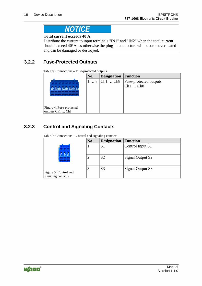
3.2.2 Fuse-Protected Outputs
Table 8: Connections – Fuse-protected outputs
Figure 4: Fuse-protected outputs Ch1 … Ch8
No. Designation Function 1 … 8 Ch1 … Ch8 Fuse-protected outputs
Ch1 … Ch8
Pos: 24.8 /Serie 787 (EPSITRON)/Ger ätebeschrei bung/Anschl üsse/Anschl üsse 787-166x - Steuer- und Signal kontakte @ 13\mod_1345544033477_21.docx @ 101808 @ 3 @ 1
3.2.3 Control and Signaling Contacts
Table 9: Connections – Control and signaling contacts
Figure 5: Control and signaling contacts
No. Designation Function 1 S1 Control Input S1
2 S2 Signal Output S2
3 S3 Signal Output S3
Pos: 25 /D okumentation allgemei n/Glieder ungselemente/---Seitenwechsel--- @ 3\mod_1221108045078_0.docx @ 21810 @ @ 1
EPSITRON® Device Description 17 787-1668 Electronic Circuit Breaker
Manual Version 1.1.0
Pos: 26 /All e Seri en (Allgemei ne Module)/Ü berschrif ten für alle Serien/Gerätebeschreibung/Anzeigeel emente - Überschrift 2 @ 4\mod_1240984390875_21.docx @ 31964 @ 2 @ 1
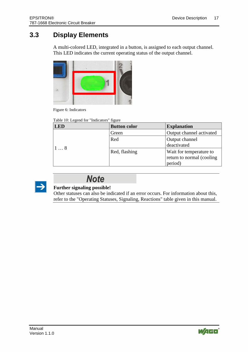
3.3 Display Elements Pos: 27 /Serie 787 (EPSITRON)/Ger ätebeschrei bung/Anzeigeelemente/Anzeigeelemente 787-1668 @ 13\mod_1343380073501_21.docx @ 101066 @ @ 1
A multi-colored LED, integrated in a button, is assigned to each output channel. This LED indicates the current operating status of the output channel.
Figure 6: Indicators
Table 10: Legend for "Indicators" figure LED Button color Explanation
1 … 8
Green Output channel activated Red Output channel
deactivated Red, flashing Wait for temperature to
return to normal (cooling period)
Further signaling possible! Other statuses can also be indicated if an error occurs. For information about this, refer to the "Operating Statuses, Signaling, Reactions" table given in this manual.
Pos: 28 /D okumentation allgemei n/Glieder ungselemente/---Seitenwechsel--- @ 3\mod_1221108045078_0.docx @ 21810 @ @ 1

18 Device Description EPSITRON® 787-1668 Electronic Circuit Breaker
Manual Version 1.1.0
Pos: 29 /All e Seri en (Allgemei ne Module)/Ü berschrif ten für alle Serien/Gerätebeschreibung/Bedienel emente - Ü berschrif t 2 @ 4\mod_1239191655456_21.docx @ 30439 @ 2 @ 1
3.4 Operating Elements Pos: 30 /Serie 787 (EPSITRON)/Ger ätebeschrei bung/Bedi enelemente/Bedienel emente 787- 1668 @ 12\mod_1341816912585_21.docx @ 99130 @ 33 @ 1
3.4.1 Buttons
A button is assigned to each output channel. Depending on the operating mode the button can have two different functions:
• During operation, the channel can be activated and de-activated.
• If an error is present, the channel can be reset.
Figure 7: Buttons
EPSITRON® Device Description 19 787-1668 Electronic Circuit Breaker
Manual Version 1.1.0
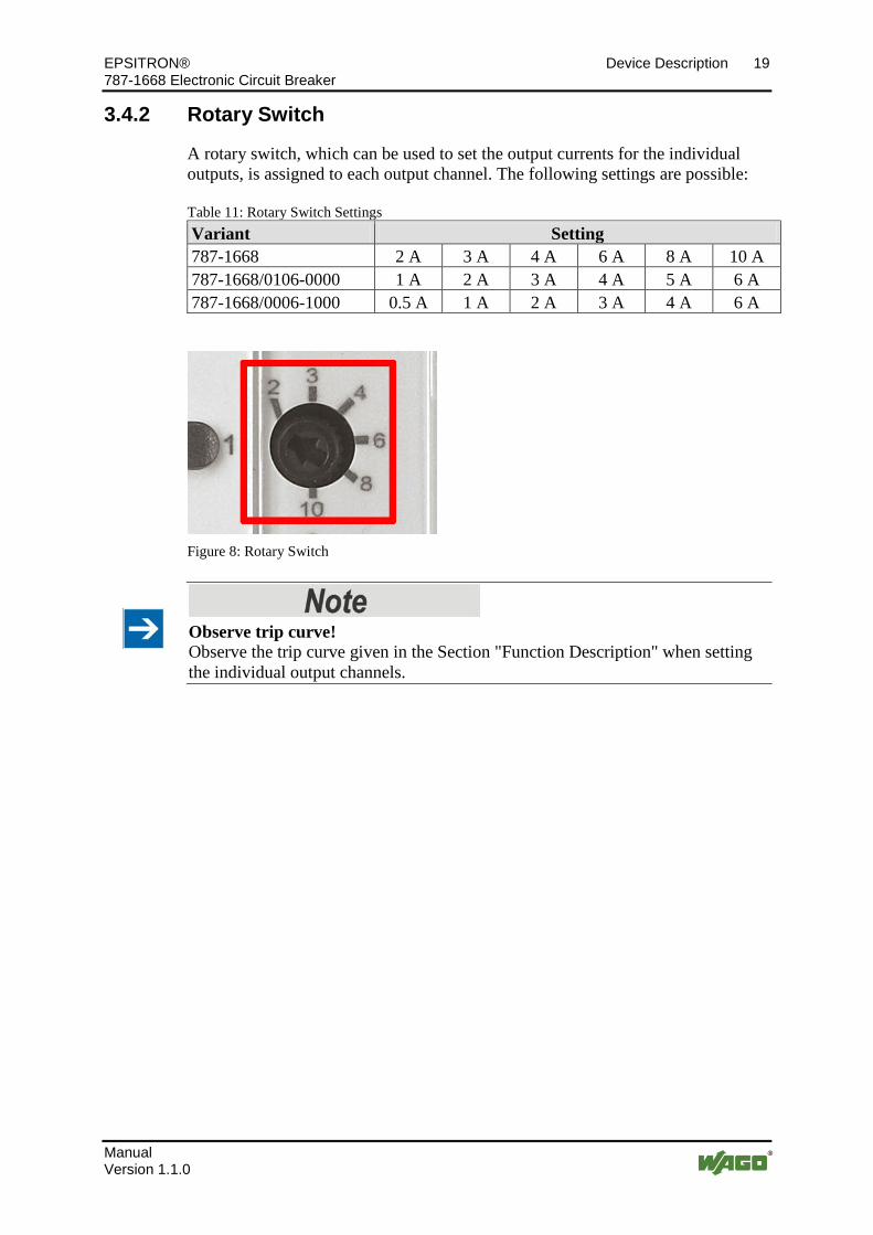
3.4.2 Rotary Switch
A rotary switch, which can be used to set the output currents for the individual outputs, is assigned to each output channel. The following settings are possible:
Table 11: Rotary Switch Settings Variant Setting 787-1668 2 A 3 A 4 A 6 A 8 A 10 A 787-1668/0106-0000 1 A 2 A 3 A 4 A 5 A 6 A 787-1668/0006-1000 0.5 A 1 A 2 A 3 A 4 A 6 A
Figure 8: Rotary Switch
Observe trip curve! Observe the trip curve given in the Section "Function Description" when setting the individual output channels.
Pos: 31 /D okumentation allgemei n/Glieder ungselemente/---Seitenwechsel--- @ 3\mod_1221108045078_0.docx @ 21810 @ @ 1

20 Device Description EPSITRON® 787-1668 Electronic Circuit Breaker
Manual Version 1.1.0
Pos: 32 /All e Seri en (Allgemei ne Module)/Ü berschrif ten für alle Serien/Gerätebeschreibung/Technische Daten - Ü berschrif t 2 @ 3\mod_1232967587687_21.docx @ 26924 @ 2 @ 1
3.5 Technical Data Pos: 33 /Serie 787 (EPSITRON)/Ger ätebeschrei bung/Technische D aten/Technische Daten 787-1668 @ 12\mod_1341822484504_21.docx @ 99133 @ 33333 @ 1
3.5.1 Device Data
Table 12: Device data Width 42 mm Height 127 mm Depth (from upper edge of DIN 35 rail) 142.5 mm Weight 440 g

EPSITRON® Device Description 21 787-1668 Electronic Circuit Breaker
Manual Version 1.1.0
3.5.2 Technical Data for "Input"
Table 13: Technical data - "Input" Nominal input voltage 24 VDC Input voltage range 18 ... 30 VDC Maximum residual ripple/ ripple for the input voltage
3 % with resistive load
Required input voltage at which the output channels are activated (activation threshold)
20 V
Input voltage at which the output channels are de-activated (trip threshold)
18 V
Maximum continuous current for the device
787-1668: 787-1668/0106-0000, 787-1668/0006-1000:
70 A 48 A
Maximum continuous current per I/O module pole
40 A
Overvoltage protection Suppressor diodes (33 V) Zero-signal current for open-circuit operation at 24 V
787-1668, 787-1668/0106-0000: 787-1668/0006-1000:
55 mA 48 mA
Power dissipation for open-circuit operation at 24 V
787-1668, 787-1668/0106-0000: 787-1668/0006-1000:
1.32 W 1.15 W
Input modules WAGO-MULTI CONNECTION SYSTEM (MCS), 721 Series Connection: 0.08 mm² … 2.5 mm² (maximum 1.5 mm² with insulated ferrule) WAGO-MULTI CONNECTION SYSTEM (MCS), 831 Series Connection: 0.5 mm² … 10 mm² (maximum 6 mm² with insulated ferrule)
22 Device Description EPSITRON® 787-1668 Electronic Circuit Breaker
Manual Version 1.1.0
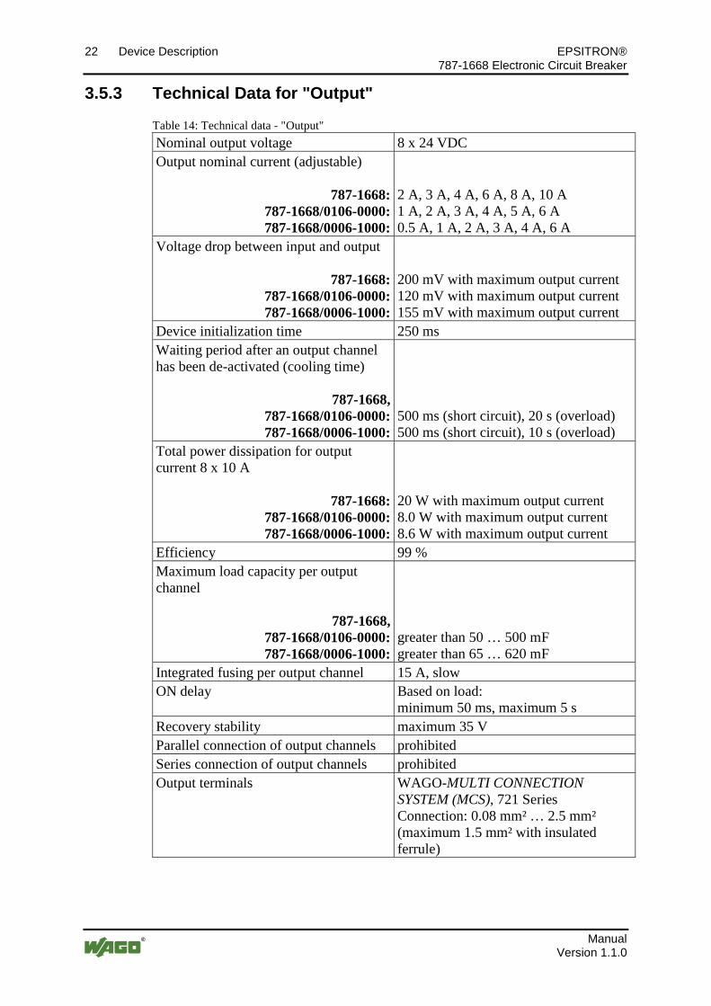
3.5.3 Technical Data for "Output"
Table 14: Technical data - "Output" Nominal output voltage 8 x 24 VDC Output nominal current (adjustable)
787-1668: 787-1668/0106-0000: 787-1668/0006-1000:
2 A, 3 A, 4 A, 6 A, 8 A, 10 A 1 A, 2 A, 3 A, 4 A, 5 A, 6 A 0.5 A, 1 A, 2 A, 3 A, 4 A, 6 A
Voltage drop between input and output
787-1668: 787-1668/0106-0000: 787-1668/0006-1000:
200 mV with maximum output current 120 mV with maximum output current 155 mV with maximum output current
Device initialization time 250 ms Waiting period after an output channel has been de-activated (cooling time)
787-1668, 787-1668/0106-0000: 787-1668/0006-1000:
500 ms (short circuit), 20 s (overload) 500 ms (short circuit), 10 s (overload)
Total power dissipation for output current 8 x 10 A
787-1668: 787-1668/0106-0000: 787-1668/0006-1000:
20 W with maximum output current 8.0 W with maximum output current 8.6 W with maximum output current
Efficiency 99 % Maximum load capacity per output channel
787-1668, 787-1668/0106-0000: 787-1668/0006-1000:
greater than 50 … 500 mF greater than 65 … 620 mF
Integrated fusing per output channel 15 A, slow ON delay Based on load:
minimum 50 ms, maximum 5 s Recovery stability maximum 35 V Parallel connection of output channels prohibited Series connection of output channels prohibited Output terminals WAGO-MULTI CONNECTION
SYSTEM (MCS), 721 Series Connection: 0.08 mm² … 2.5 mm² (maximum 1.5 mm² with insulated ferrule)
EPSITRON® Device Description 23 787-1668 Electronic Circuit Breaker
Manual Version 1.1.0
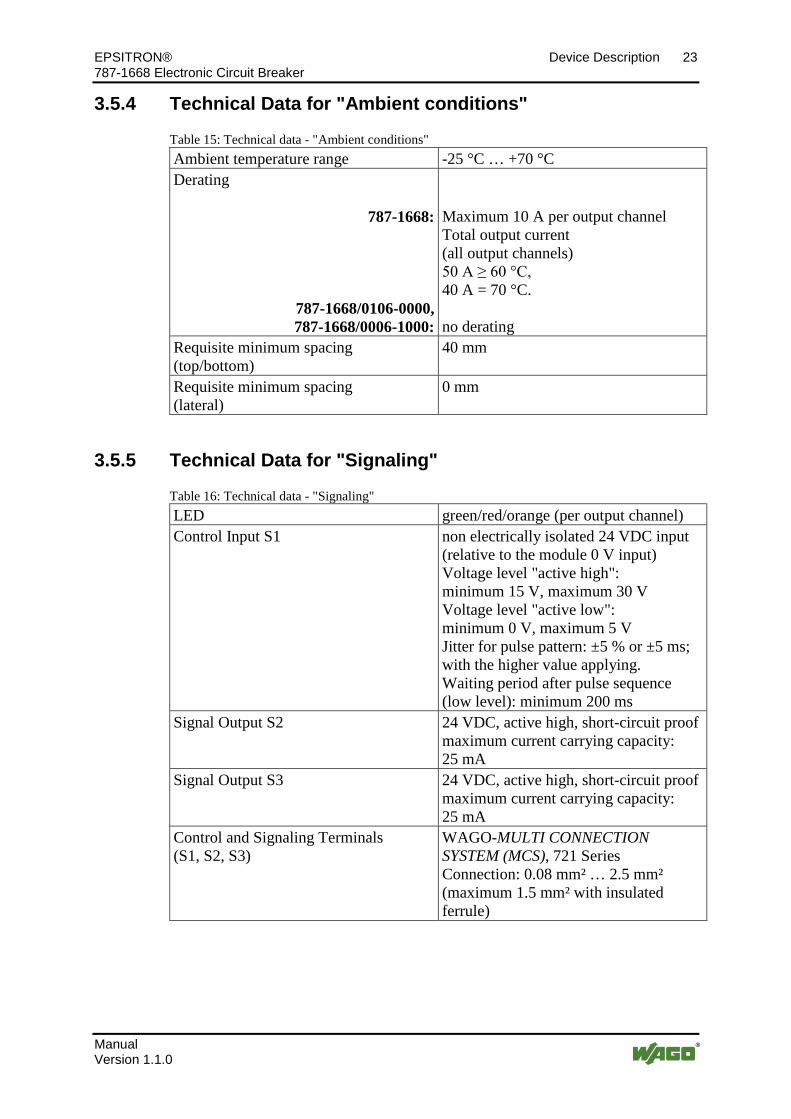
3.5.4 Technical Data for "Ambient conditions"
Table 15: Technical data - "Ambient conditions" Ambient temperature range -25 °C … +70 °C Derating
787-1668:
787-1668/0106-0000, 787-1668/0006-1000:
Maximum 10 A per output channel Total output current (all output channels) 50 A ≥ 60 °C, 40 A = 70 °C. no derating
Requisite minimum spacing (top/bottom)
40 mm
Requisite minimum spacing (lateral)
0 mm
3.5.5 Technical Data for "Signaling"
Table 16: Technical data - "Signaling" LED green/red/orange (per output channel) Control Input S1 non electrically isolated 24 VDC input
(relative to the module 0 V input) Voltage level "active high": minimum 15 V, maximum 30 V Voltage level "active low": minimum 0 V, maximum 5 V Jitter for pulse pattern: ±5 % or ±5 ms; with the higher value applying. Waiting period after pulse sequence (low level): minimum 200 ms
Signal Output S2 24 VDC, active high, short-circuit proof maximum current carrying capacity: 25 mA
Signal Output S3 24 VDC, active high, short-circuit proof maximum current carrying capacity: 25 mA
Control and Signaling Terminals (S1, S2, S3)
WAGO-MULTI CONNECTION SYSTEM (MCS), 721 Series Connection: 0.08 mm² … 2.5 mm² (maximum 1.5 mm² with insulated ferrule)
Pos: 34 /D okumentation allgemei n/Glieder ungselemente/---Seitenwechsel--- @ 3\mod_1221108045078_0.docx @ 21810 @ @ 1
24 Device Description EPSITRON® 787-1668 Electronic Circuit Breaker
Manual Version 1.1.0
Pos: 35 /All e Seri en (Allgemei ne Module)/Ü berschrif ten für alle Serien/Gerätebeschreibung/Zul assungen - Überschrift 2 @ 3\mod_1224055364109_21.docx @ 24030 @ 2 @ 1
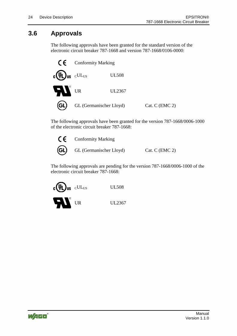
3.6 Approvals Pos: 36.1 /Serie 787 (EPSITRON)/Ger ätebeschrei bung/Zulassungen/Zulassungen Elektr. Schutzschalter 787- xxxx Allgemein, Standar dvers. und spezif . Variante - Einl. @ 13\mod_1347451782755_21.docx @ 102663 @ @ 1
The following approvals have been granted for the standard version of the electronic circuit breaker 787-1668 and version 787-1668/0106-0000:
Pos: 36.2 /All e Seri en ( Allgemei ne Module)/Zulassungen/Standardzulassungen/C E (Konformi tätskennzeichnung) @ 3\mod_1224494777421_21.docx @ 24276 @ @ 1
Conformity Marking Pos : 36.3 /All e Seri en ( Allgemei ne Module)/Zulassungen/Standardzulassungen/cU Lus (U L508) @ 3\mod_1224055013140_0.docx @ 24020 @ @ 1
CULUS UL508
Pos: 36.4 /All e Seri en ( Allgemei ne Module)/Zulassungen/Standardzulassungen/U L2367 @ 18\mod_1391419979318_0.docx @ 144214 @ @ 1
UR UL2367
Pos: 36.5 /All e Seri en ( Allgemei ne Module)/Zulassungen/Schiffszul assungen/GL (Germanischer Lloyd) C at. C ( EMC 2) @ 18\mod_1392645436824_0.docx @ 145658 @ @ 1
GL (Germanischer Lloyd) Cat. C (EMC 2)
Pos : 36.6 /Dokumentation allgemei n/Glieder ungselemente/------Leerzeile------ @ 3\mod_1224662755687_0.docx @ 24460 @ @ 1
Pos: 36.7 /Serie 787 (EPSITRON)/Ger ätebeschrei bung/Zulassungen/Zulassungen Elektr. Schutzschalter 787- xxxx Allgemein, spezif. Variante - Ei nl. @ 18\mod_1391088086008_21.docx @ 144056 @ @ 1
The following approvals have been granted for the version 787-1668/0006-1000 of the electronic circuit breaker 787-1668:
Pos: 36.8 /All e Seri en ( Allgemei ne Module)/Zulassungen/Standardzulassungen/C E (Konformi tätskennzeichnung) @ 3\mod_1224494777421_21.docx @ 24276 @ @ 1
Conformity Marking Pos : 36.9 /All e Seri en ( Allgemei ne Module)/Zulassungen/Schiffszul assungen/GL (Germanischer Lloyd) C at. C ( EMC 2) @ 18\mod_1392645436824_0.docx @ 145658 @ @ 1
GL (Germanischer Lloyd) Cat. C (EMC 2)
Pos : 36.10 /D okumentati on allgemei n/Gli ederungsel emente/------Leerzeile------ @ 3\mod_1224662755687_0.docx @ 24460 @ @ 1
Pos: 36.11 /Serie 787 ( EPSITR ON)/Gerätebeschrei bung/Zul assungen/Zul. i n Vorb. Elektr. Schutzschalter 787- xxxx Allgemein, spezi f. Vari ante - Ei nl. @ 18\mod_1391088393401_21.docx @ 144064 @ @ 1
The following approvals are pending for the version 787-1668/0006-1000 of the electronic circuit breaker 787-1668:
Pos: 36.12 /Alle Serien (Allgemeine M odul e)/Zulassungen/Standar dzulassungen/cU Lus (UL508) @ 3\mod_1224055013140_0.docx @ 24020 @ @ 1
CULUS UL508
Pos: 36.13 /Alle Serien (Allgemeine M odul e)/Zulassungen/Standar dzulassungen/UL2367 @ 18\mod_1391419979318_0.docx @ 144214 @ @ 1
UR UL2367
Pos: 37 /D okumentation allgemei n/Glieder ungselemente/---Seitenwechsel--- @ 3\mod_1221108045078_0.docx @ 21810 @ @ 1
EPSITRON® Device Description 25 787-1668 Electronic Circuit Breaker
Manual Version 1.1.0
Pos: 38 /All e Seri en (Allgemei ne Module)/Ü berschrif ten für alle Serien/Gerätebeschreibung/Nor men und Richtlini en - Überschrift 2 @ 4\mod_1242804031875_21.docx @ 33646 @ 2 @ 1
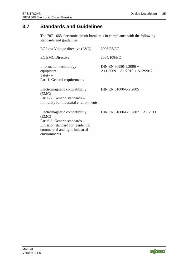
3.7 Standards and Guidelines Pos: 39.1 /Serie 787 (EPSITRON)/Ger ätebeschrei bung/N or men und Richtli nien/N ormen und Richtli nien Elektronischer Schutzschalter 787- xxxx, ohne Variantenangabe - Ei nlei tung @ 13\mod_1347452665951_21.docx @ 102670 @ @ 1
The 787-1668 electronic circuit breaker is in compliance with the following standards and guidelines:
Pos: 39.2 /All e Seri en ( Allgemei ne Module)/N or men und Richtli nien/Standardnor men/EG-Niederspannungsrichtli nie 2006/ 95/EG-Ni ederspannungsrichtli nie 2006/ 95/ EG @ 7\mod_1274262383272_21.docx @ 56632 @ @ 1
EC Low Voltage directive (LVD) 2006/95/EC Pos: 39.3 /All e Seri en ( Allgemei ne Module)/N or men und Richtli nien/EMV-N ormen - Standar d/EG- EMV-Richtlini e 2004/108/EG-EM V-Richtlinie 2004/108/EG @ 7\mod_1274262373820_21.docx @ 56628 @ @ 1
EC EMC Directive 2004/108/EC Pos: 39.4 /All e Seri en ( Allgemei ne Module)/N or men und Richtli nien/Sicherheitsnormen/Sicherheit: DIN EN 60950- 1:2006 + A11:2009 + A1:2010 + A12:2012 (Ergänzung mit "und") @ 18\mod_1391077570696_21.docx @ 143968 @ @ 1
Information technology equipment – Safety – Part 1: General requirements
DIN EN 60950-1:2006 + A11:2009 + A1:2010 + A12:2012
Pos: 39.5 /All e Seri en ( Allgemei ne Module)/N or men und Richtli nien/Sicherheitsnormen/Sicherheit: DIN EN 61000- 6-2:2005 @ 18\mod_1391172357008_21.docx @ 144102 @ @ 1
Electromagnetic compatibility (EMC) – Part 6-2: Generic standards – Immunity for industrial environments
DIN EN 61000-6-2:2005
Pos: 39.6 /All e Seri en ( Allgemei ne Module)/N or men und Richtli nien/Sicherheitsnormen/Sicherheit: DIN EN 61000- 6-3:2007 + A1:2011 (Ergänzung mit "und") @ 18\mod_1391173469051_21.docx @ 144166 @ @ 1
Electromagnetic compatibility (EMC) – Part 6-3: Generic standards – Emission standard for residential, commercial and light-industrial environments
DIN EN 61000-6-3:2007 + A1:2011
Pos: 40 /D okumentation allgemei n/Glieder ungselemente/---Seitenwechsel--- @ 3\mod_1221108045078_0.docx @ 21810 @ @ 1

26 Mounting EPSITRON® 787-1668 Electronic Circuit Breaker
Manual Version 1.1.0
Pos: 41 /All e Seri en (Allgemei ne Module)/Ü berschrif ten für alle Serien/Monti eren - D emontieren/M ontier en - Überschrift 1 @ 3\mod_1225446744750_21.docx @ 24900 @ 1 @ 1
4 Mounting Pos: 42 /Serie 787 (EPSITRON)/M ontier en/Montage 787- 16xx @ 11\mod_1317296048899_21.docx @ 80170 @ 22 @ 1
4.1 Mounting Pos: 59 /Serie 787 (EPSITRON)/M ontier en/Montage 787- xxxx @ 11\mod_1317296048899_6.docx @ 80169 @ 22 @ 1
The device is designed for mounting on a DIN 35 rail.
4.2 Mounting the Device on the DIN 35 Rail
Figure 9: Mounting the device on the DIN 35 rail
1. Tilt the device slightly.
2. Place the device with its DIN rail guide on the top edge of the DIN rail.
3. Slide the device all the way down.
Figure 10: Mounting the device on the DIN 35 rail
4. Press it down against the bottom fastener until you hear it lock into place.
5. Lightly shake the device to ensure that it is correctly locked into place.

EPSITRON® Mounting 27 787-1668 Electronic Circuit Breaker
Manual Version 1.1.0
4.3 Removing the Device from the DIN 35 Rail
Figure 11: Removing the device from the DIN 35 rail
1. Use a screwdriver to press down on the locking tab.
Figure 12: Removing the device from the DIN 35 rail
2. Pull the device out at the bottom edge of the DIN 35 rail. Pos: 43 /D okumentation allgemei n/Glieder ungselemente/---Seitenwechsel--- @ 3\mod_1221108045078_0.docx @ 21810 @ @ 1

28 Connect Devices EPSITRON® 787-1668 Electronic Circuit Breaker
Manual Version 1.1.0
Pos: 44 /All e Seri en (Allgemei ne Module)/Ü berschrif ten für alle Serien/Anschließen/Ger äte anschließen - Ü berschrift 1 @ 3\mod_1234172889468_21.docx @ 27460 @ 1 @ 1
5 Connect Devices Pos: 45 /All e Seri en (Allgemei ne Module)/Ü berschrif ten für alle Serien/Anschließen/Anschl ussbeispiel - Überschrift 2 @ 4\mod_1242621672468_21.docx @ 33293 @ 2 @ 1
5.1 Connection Example Pos: 46 /Serie 787 (EPSITRON)/Anschließen/Anschlussbeispi el 787-1668 @ 13\mod_1343377823951_21.docx @ 101063 @ @ 1
Figure 13: Connection example
Pos: 47 /D okumentation allgemei n/Glieder ungselemente/---Seitenwechsel--- @ 3\mod_1221108045078_0.docx @ 21810 @ @ 1

EPSITRON® Function Description 29 787-1668 Electronic Circuit Breaker
Manual Version 1.1.0
Pos: 48 /All e Seri en (Allgemei ne Module)/Ü berschrif ten für alle Serien/Funktionsbeschr eibung - Ü berschrif t 1 @ 4\mod_1239025975389_21.docx @ 30003 @ 1 @ 1
6 Function Description Pos: 49 /Serie 787 (EPSITRON)/Funkti onsbeschrei bung/Unter- und Überspannungser kennung 787-166x @ 13\mod_1343392113095_21.docx @ 101122 @ 2 @ 1
6.1 Undervoltage and Overvoltage Detection This device operates in a voltage range between 18 … 30 VDC.
Pos: 50 /Serie 787 (EPSITRON)/F unkti onsbeschrei bung/Ausl ösekennlinie 787-166x @ 13\mod_1343389182679_21.docx @ 101119 @ 233345554 @ 1
6.2 Trip Curves
6.2.1 Trip Curve for the 10 A Circuit Breaker 787-1668
Figure 14: Trip Curve for the 10 A Circuit Breaker 787-1668

30 Function Description EPSITRON® 787-1668 Electronic Circuit Breaker
Manual Version 1.1.0
6.2.2 Trip Curve for the 6 A Circuit Breaker 787-1668/0106-0000
Figure 15: Trip Curve for the 6 A Circuit Breaker 787-1668/0106-0000
6.2.3 Trip Curve for the 6 A Circuit Breaker with Active Current
Limitation 787-1668/0006-1000
Figure 16: Trip Curve for the 6 A Circuit Breaker with Active Current Limitation 787-1668/0006-1000

EPSITRON® Function Description 31 787-1668 Electronic Circuit Breaker
Manual Version 1.1.0
6.2.3.1 Response of the Electronic Circuit Breaker with Active Current Limitation
Nominal current
Shutdown takes place after 5 seconds,
with an over-current greater than within 50 milliseconds … 5 seconds,
with an over-current between (Threshold 1) (Threshold 2) (Threshold 3)
0.5 A 0.75 A 1.00 A 1.20 A 1 A 1.20 A 1.50 A 1.70 A 2 A 2.20 A 3.00 A 3.40 A 3 A 3.30 A 4.50 A 5.10 A 4 A 4.40 A 6.00 A 6.80 A 6 A 6.60 A 8.00 A 10.2 A
The function is activated when
• an over-current measured at an output is greater than the corresponding threshold for the set nominal current (Threshold 1).
• the measured over-current is present for more than 0.1 ms.
The activated circuit breaker can respond in one of three ways:
1. An over-current is present that is greater than Threshold 3
2. An over-current is present that is greater than Threshold 1, but less than Threshold 2
3. An over-current is present that is greater than the nominal current, but less than Threshold 1
32 Function Description EPSITRON® 787-1668 Electronic Circuit Breaker
Manual Version 1.1.0
6.2.3.1.1 Response 1: Over-current present that is greater than Threshold 3
If an over-current is present that is greater than Threshold 3, the current will be limited to a value situated between Threshold 2 and Threshold 3. This limitation is effective for at least 50 ms and functions as a variable series resistor. The output voltage is less than the input voltage.
If the over-current does not decrease, the output concerned will be deactivated within a period of 50 ms … 5 s.
6.2.3.1.2 Response 2: Over-current present that is greater than Threshold 1,
but less than Threshold 2
If an over-current is present that is greater than Threshold 1, but less than Threshold 2, the output will be deactivated after 5 s.
6.2.3.1.3 Response 3: Over-current present that is greater than the nominal
current, but less than Threshold 1
If an over-current is present that is greater than the nominal current, but less than Threshold 1, the output is not deactivated. This over-current is report, however.
6.2.3.2 Selective immediate deactivation
If the output voltage from the power supply unit drops below 20 V, all outputs with current greater than the set nominal current are deactivated within 16 ms.
Pos: 51 /D okumentation allgemei n/Glieder ungselemente/---Seitenwechsel--- @ 3\mod_1221108045078_0.docx @ 21810 @ @ 1
EPSITRON® Function Description 33 787-1668 Electronic Circuit Breaker
Manual Version 1.1.0
Pos: 52 /Serie 787 (EPSITRON)/Funkti onsbeschrei bung/Ei nschal ten von kapaziti ven Las ten 787- 166x @ 12\mod_1341401971175_21.docx @ 98843 @ 233 @ 1
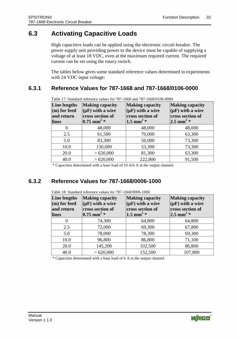
6.3 Activating Capacitive Loads High capacitive loads can be applied using the electronic circuit breaker. The power supply unit providing power to the device must be capable of supplying a voltage of at least 18 VDC, even at the maximum required current. The required current can be set using the rotary switch.
The tables below gives some standard reference values determined in experiments with 24 VDC input voltage:
6.3.1 Reference Values for 787-1668 and 787-1668/0106-0000
Table 17: Standard reference values for 787-1668 and 787-1668/0106-0000 Line lengths (m) for feed and return lines
Making capacity (µF) with a wire cross section of 0.75 mm2 *
Making capacity (µF) with a wire cross section of 1.5 mm2 *
Making capacity (µF) with a wire cross section of 2.5 mm2 *
0 48,000 48,000 48,000 2.5 61,500 70,000 63,300 5.0 83,300 50,000 73,300 10.0 130,000 53,300 73,300 20.0 > 620,000 81,300 63,300 40.0 > 620,000 222,800 91,500
* Capacities determined with a base load of 10 A/6 A at the output channel.
6.3.2 Reference Values for 787-1668/0006-1000
Table 18: Standard reference values for 787-1668/0006-1000 Line lengths (m) for feed and return lines
Making capacity (µF) with a wire cross section of 0.75 mm2 *
Making capacity (µF) with a wire cross section of 1.5 mm2 *
Making capacity (µF) with a wire cross section of 2.5 mm2 *
0 74,300 64,800 64,800 2.5 72,000 69,300 67,800 5.0 78,000 78,300 69,300 10.0 96,800 86,800 71,100 20.0 145,200 102,500 86,800 40.0 > 620,000 152,500 107,800
* Capacities determined with a base load of 6 A at the output channel.
Pos: 53 /Serie 787 (EPSITRON)/Funkti onsbeschrei bung/Betri ebszus tände, Sig nalisi erung, R eaktionen 787- 166x @ 12\mod_1341474059753_21.docx @ 98960 @ 2 @ 1

34 Function Description EPSITRON® 787-1668 Electronic Circuit Breaker
Manual Version 1.1.0
6.4 Operating Statuses, Signaling, Reactions Table 19: Operating statuses, signaling, reactions Status Operating status Channel LED Signal output
S3 (common signal)
Button is pressed Transition to …
Control input S1 Transition to …
0 Device initialization. 1
off off 0 V - -
1 Output activated, function OK.
on Green 24 V Status 3 Status 3 (via bit pattern)
2 Output current greater than nominal current. 2
on Green flashing
24 V Status 3 Status 3 (via bit pattern)
3 Output de-activated manually, or by control input S1. 3
off Red 24 V Status 1 Status 1 (via bit pattern)
4 Output de-activated due to excessive current. Cooling (waiting) period is active. 4
off Red flashing
0 V - -
5 Output de-activated due to excessive current. Cooling (waiting) period is completed. 5
off Orange flashing
0 V Status 3 Status 1 (using pulse longer than 0.5 s)
6 Device error: Defective fuse detected.
off Red flashing, rapid
0 V Status 6 -
1 The outputs are re-activated based on the load applied as soon as device initialization is concluded.
2 The output is de-activated automatically in accordance with the given trip curve. The device then switches to Status 4.
3 The status is saved when the device is switched off. 4 After a defined waiting period (cooling time), the output switches to Status 5. The
remaining time of the waiting period is saved when the device is switched off. This time must first elapse when the device is switched on again. This feature protects the switching elements against any overloading.
5 The output can be re-activated as follows: • by pressing the associated button twice, or • by applying a pulse at control input S1. The device then switches to Status 1.

EPSITRON® Function Description 35 787-1668 Electronic Circuit Breaker
Manual Version 1.1.0
Abbildung 17: Operating Statuses, Signaling, Reactions
Pos: 54 /D okumentation allgemei n/Glieder ungselemente/---Seitenwechsel--- @ 3\mod_1221108045078_0.docx @ 21810 @ @ 1

36 Function Description EPSITRON® 787-1668 Electronic Circuit Breaker
Manual Version 1.1.0
Pos: 55 /Serie 787 (EPSITRON)/Funkti onsbeschrei bung/Zuschaltverzögerung 787-166x @ 12\mod_1341479703716_21.docx @ 98963 @ 2 @ 1
6.5 ON Delay for Specific Channels The outputs are activated in a staggered manner in the order of their channel numbers as soon as a minimum input voltage is present. Outputs which have been de-activated manually, or by a reset signal, are skipped in this process.
The time at which the next output in the sequence is activated is based on the following conditions:
• At least 50 ms must elapse after activation of the previous output.
• The output current of the previously activated output must lie below the nominal value set for the output.
Pos: 56 /D okumentation allgemei n/Glieder ungselemente/---Seitenwechsel--- @ 3\mod_1221108045078_0.docx @ 21810 @ @ 1

EPSITRON® Function Description 37 787-1668 Electronic Circuit Breaker
Manual Version 1.1.0
Pos: 57 /Serie 787 (EPSITRON)/Funkti onsbeschrei bung/Digital eingang S1 787- 1668 @ 12\mod_1341908222413_21.docx @ 99460 @ 233 @ 1
6.6 Control Input S1 A signal between S1 and 0 V has the effect that
• all channels previously de-activated due to overloading can now be re-activated.
• specific channels can be activated or de-activated.
6.6.1 Re-activating Tripped Channels
Apply a signal for at least 0.5 seconds. All channels previously de-activated due to overloading are then re-activated in sequential order, based on the load applied.
Figure 18: Example of re-activation via control input S1, or signal output S3.
38 Function Description EPSITRON® 787-1668 Electronic Circuit Breaker
Manual Version 1.1.0
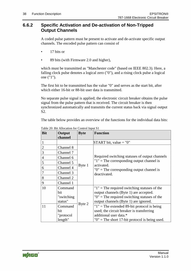
6.6.2 Specific Activation and De-activation of Non-Tripped Output Channels
A coded pulse pattern must be present to activate and de-activate specific output channels. The encoded pulse pattern can consist of
• 17 bits or
• 89 bits (with Firmware 2.0 and higher),
which must be transmitted as "Manchester code" (based on IEEE 802.3). Here, a falling clock pulse denotes a logical zero ("0"), and a rising clock pulse a logical one ("1").
The first bit to be transmitted has the value "0" and serves as the start bit, after which either 16-bit or 88-bit user data is transmitted.
No separate pulse signal is applied; the electronic circuit breaker obtains the pulse signal from the pulse pattern that is received. The circuit breaker is then synchronized automatically and transmits the current status back via signal output S2.
The table below provides an overview of the functions for the individual data bits:
Table 20: Bit Allocation for Control Input S1 Bit Output
channel Byte Function
1 START bit, value = "0" 2 Channel 8
Byte 1
Required switching statuses of output channels "1" = The corresponding output channel is activated. "0" = The corresponding output channel is deactivated.
3 Channel 7 4 Channel 6 5 Channel 5 6 Channel 4 7 Channel 3 8 Channel 2 9 Channel 1 10
Command bit "switching status" Byte 2
"1" = The required switching statuses of the output channels (Byte 1) are accepted. "0" = The required switching statuses of the output channels (Byte 1) are ignored.
11 Command bit "protocol length"
"1" = The extended 89-bit protocol is being used; the circuit breaker is transferring additional user data.* "0" = The short 17-bit protocol is being used.

EPSITRON® Function Description 39 787-1668 Electronic Circuit Breaker
Manual Version 1.1.0
12 Command bit "current value"
"1" = The momentary input voltage and the nominal currents set at the current selection switch are being transferred.* "0" = The momentary input voltage and the momentary output currents are being transferred.**
13
Pulse signal for signal output S2, value = "0"
14 15 16 17 18 … 25 Byte 3
Pulse signal for signal output S2, value = "0"
26 … 33 Channel 1 Byte 4 34 … 41 Channel 2 Byte 5 42 … 49 Channel 3 Byte 6 50 … 57 Channel 4 Byte 7 58 … 65 Channel 5 Byte 8 66 … 73 Channel 6 Byte 9 74 … 81 Channel 7 Byte 10 82 … 89 Channel 8 Byte 11 18 or 90
STOP bit (1.5 pulse cycles) For 17-bit protocol: Bit 18 For 89-bit protocol: Bit 90
* This function is supports starting with Firmware 2.10 for the 787-1668 and 787-1668/0106-0000 and with Firmware 2.00 for the 787-1668/0006-1000.
** This function is supported starting with Firmware 2.10 for the 787-1668/0006-1000. Depending on the valence of bit 12 (byte 2), either the set nominal currents or the momentary output currents are transferred in addition to the momentary input voltage (see Table 22).
Electronic circuit breakers without active current limitation supply only the momentary input voltage and the set nominal currents. Output currents are not transferred.

40 Function Description EPSITRON® 787-1668 Electronic Circuit Breaker
Manual Version 1.1.0
Changing of the signal voltage from 15 V … 30 VDC to 0 V … 5 VDC (falling clock pulse) corresponds to a logical zero ("0"). Changing of the signal voltage from 0 V … 5 VDC to 15 V … 30 VDC (rising clock pulse) corresponds to a logical one ("1"). The minimum pulse period is 70 ms, the maximum 200 ms.
A jitter of ±5 % or ±5 ms is acceptable, with the higher value applying.
STOP Bit: The STOP bit uses 1.5 pulse cycles. During this time, the PLC may not transmit any further bit.
Once the pulse pattern has been transmitted, S1 and S2 are returned to Low. A new pulse pattern cannot be transmitted until after a period of 200 ms.
The coded pulse pattern must be generated in the PLC via an XOR link from an auxiliary clock pulse and the data bits. This is illustrated by the examples in the figures below:
Figure 19: Standard 17-bit protocol
Figure 20: Extended 89-bit protocol

EPSITRON® Function Description 41 787-1668 Electronic Circuit Breaker
Manual Version 1.1.0
Table 21: Key for the "Standard 17-bit protocol" and "Extended 89-bit protocol" figures Description Description tZ Cycle duration: 70 ms … 200 ms GH Generated auxiliary clock pulse in the PLC DB Data bits from PLC to device S3 PLC output (control input S1 of the circuit breaker)
created from an XOR link between data bits and an auxiliary clock pulse
S2 PLC input SPS (signal output S2 of the circuit breaker) Data bits valid at the falling clock pulse
Ch1 … Ch8 Output channel 1 … Output channel 8
Function Blocks for PLC Upon request, WAGO can provide a library with CoDeSys function blocks for your PLC. Simply contact our Support unit.
Pos: 58 /D okumentation allgemei n/Glieder ungselemente/---Seitenwechsel--- @ 3\mod_1221108045078_0.docx @ 21810 @ @ 1

42 Function Description EPSITRON® 787-1668 Electronic Circuit Breaker
Manual Version 1.1.0
Pos: 59 /Serie 787 (EPSITRON)/Funkti onsbeschrei bung/Digital ausg ang S2 787-1668 @ 12\mod_1341924817227_21.docx @ 99463 @ 2 @ 1
6.7 Signal Output S2 The status of the 8 output channels can be queried at signal output S2. This output channel is short-circuit proof and has a common potential with the power supply ground.
Use signal output S2 with a PLC! Connect the supply ground of the electronic circuit breaker with the ground of the PLC when you use signal output S2 with a PLC!
When a coded sampled signal is transmitted via control input S1, the circuit breaker is synchronized automatically. The current status of the output channels is then transmitted via signal output S2.
The table below provides an overview of the 17 data bits at signal output S2. A distinction is drawn here between the status "on/off" and the error status "tripped/overcurrent".

EPSITRON® Function Description 43 787-1668 Electronic Circuit Breaker
Manual Version 1.1.0
Table 22: Bit allocation for signal output S2 Bit Output
channel Byte Function
1 START bit, value = "0" 2 Channel 8
Byte 1
Switching status "1" = The corresponding output channel is activated. "0" = The corresponding output channel is deactivated. Error status "1" = The corresponding output channel is still activated, but with over-current (output current < nominal current, longer than 1 s). "0" = The corresponding output channel has been deactivated due to over-current.
3 Channel 7 4 Channel 6 5 Channel 5 6 Channel 4 7 Channel 3 8 Channel 2 9 Channel 1
10 Channel 8
Byte 2 "1" = Error status indicated in Byte 1. "0" = Switching status indicated in Byte 1
11 Channel 7 12 Channel 6 13 Channel 5 14 Channel 4 15 Channel 3 16 Channel 2 17 Channel 1 18 … 25 Byte 3 Current input voltage
((value transmitted)/16) + 16 V 26 … 33 Channel 1 Byte 4 Current *) Output channel 1 34 … 41 Channel 2 Byte 5 Current *) Output channel 2 42 … 49 Channel 3 Byte 6 Current *) Output channel 3 50 … 57 Channel 4 Byte 7 Current *) Output channel 4 58 … 65 Channel 5 Byte 8 Current *) Output channel 5 66 … 73 Channel 6 Byte 9 Current *) Output channel 6 74 … 81 Channel 7 Byte 10 Current *) Output channel 7 82 … 89 Channel 8 Byte 11 Current *) Output channel 8 18 or 90
STOP bit (1.5 pulse cycles) For 17-bit protocol: Bit 18 For 89-bit protocol: Bit 90
*) (value transmitted)/16 A Depending on the valence of bit 12 (byte 2), either the set nominal currents or the momentary output currents are transferred in addition to the momentary input voltage (see Table 20).
Electronic circuit breakers without active current limitation supply only the momentary input voltage and the set nominal currents. Output currents are not transferred.
Pos: 60 /D okumentation allgemei n/Glieder ungselemente/---Seitenwechsel--- @ 3\mod_1221108045078_0.docx @ 21810 @ @ 1
44 Function Description EPSITRON® 787-1668 Electronic Circuit Breaker
Manual Version 1.1.0
Pos: 61 /Serie 787 (EPSITRON)/Funkti onsbeschrei bung/Kommuni kati on S1/S2 787-166x @ 13\mod_1346932353562_21.docx @ 102430 @ 2 @ 1
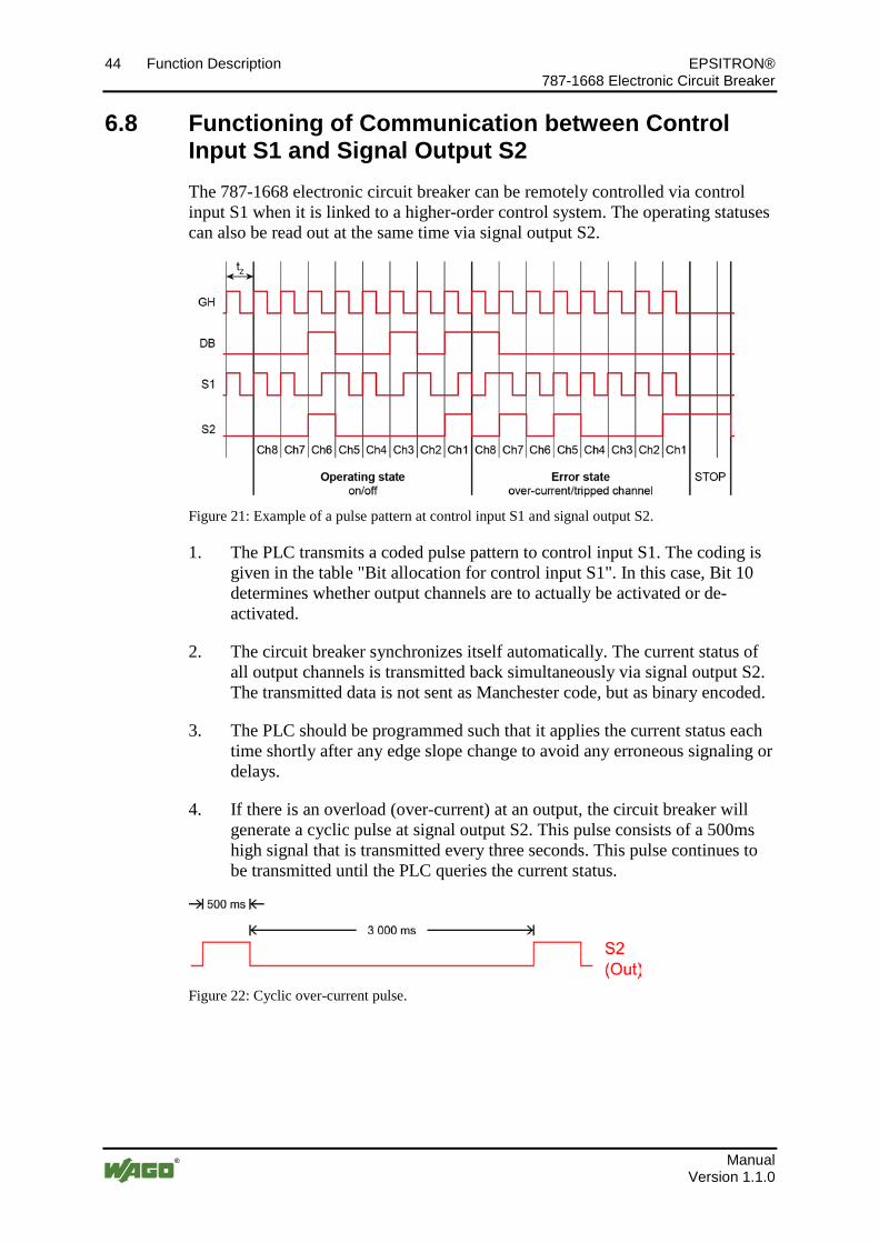
6.8 Functioning of Communication between Control Input S1 and Signal Output S2 The 787-1668 electronic circuit breaker can be remotely controlled via control input S1 when it is linked to a higher-order control system. The operating statuses can also be read out at the same time via signal output S2.
Figure 21: Example of a pulse pattern at control input S1 and signal output S2.
1. The PLC transmits a coded pulse pattern to control input S1. The coding is given in the table "Bit allocation for control input S1". In this case, Bit 10 determines whether output channels are to actually be activated or de-activated.
2. The circuit breaker synchronizes itself automatically. The current status of all output channels is transmitted back simultaneously via signal output S2. The transmitted data is not sent as Manchester code, but as binary encoded.
3. The PLC should be programmed such that it applies the current status each time shortly after any edge slope change to avoid any erroneous signaling or delays.
4. If there is an overload (over-current) at an output, the circuit breaker will generate a cyclic pulse at signal output S2. This pulse consists of a 500ms high signal that is transmitted every three seconds. This pulse continues to be transmitted until the PLC queries the current status.
Figure 22: Cyclic over-current pulse.
Pos: 62 /D okumentation allgemei n/Glieder ungselemente/---Seitenwechsel--- @ 3\mod_1221108045078_0.docx @ 21810 @ @ 1

EPSITRON® Function Description 45 787-1668 Electronic Circuit Breaker
Manual Version 1.1.0
Pos: 63 /Serie 787 (EPSITRON)/Funkti onsbeschrei bung/Digital ausg ang S3 787-1668 @ 12\mod_1342009618998_21.docx @ 99680 @ 2 @ 1
6.9 Signal Output S3 A group signal can be queried at signal output S3 to determine the status of the 8 channels. In contrast to signal output S2, output S3 delivers a 24 VDC voltage if no channel has been tripped. This voltage drops to 0 V as soon as at least one channel has been tripped.
This output is short-circuit proof and can withstand a maximum load of 20 mA. It also has a common potential with the power supply ground.
Protect the signal output against voltage peaks! Voltage peaks can occur at signal output S3 when a relay connected to the unit is de-activated. This can damage or destroy the signal output. We recommend installing a recovery diode in parallel to the relay to prevent this.
=== Ende der Liste für Textmar ke Inhalt_mitte ===

46 List of Figures EPSITRON® 787-1668 Electronic Circuit Breaker
Manual Version 1.1.0
Pos: 65 /D okumentation allgemei n/Verzeichnisse/Abbil dungsverzeichnis - Überschrift oG und Verzeichnis @ 3\mod_1219222916765_21.docx @ 21080 @ @ 1
List of Figures Figure 1: View of device ....................................................................................... 14 Figure 2: 24 V input .............................................................................................. 15 Figure 3: 0 V input ................................................................................................ 15 Figure 4: Fuse-protected outputs Ch1 … Ch8 ....................................................... 16 Figure 5: Control and signaling contacts ............................................................... 16 Figure 6: Indicators ............................................................................................... 17 Figure 7: Buttons ................................................................................................... 18 Figure 8: Rotary Switch ........................................................................................ 19 Figure 9: Mounting the device on the DIN 35 rail ................................................ 26 Figure 10: Mounting the device on the DIN 35 rail .............................................. 26 Figure 11: Removing the device from the DIN 35 rail ......................................... 27 Figure 12: Removing the device from the DIN 35 rail ......................................... 27 Figure 13: Connection example ............................................................................ 28 Figure 14: Trip Curve for the 10 A Circuit Breaker 787-1668 ............................. 29 Figure 15: Trip Curve for the 6 A Circuit Breaker 787-1668/0106-0000 ............. 30 Figure 16: Trip Curve for the 6 A Circuit Breaker with Active Current Limitation
787-1668/0006-1000 .................................................................................... 30 Abbildung 17: Operating Statuses, Signaling, Reactions ...................................... 35 Figure 18: Example of re-activation via control input S1, or signal output S3. .... 37 Figure 19: Standard 17-bit protocol ...................................................................... 40 Figure 20: Extended 89-bit protocol ..................................................................... 40 Figure 21: Example of a pulse pattern at control input S1 and signal output S2. . 44 Figure 22: Cyclic over-current pulse. .................................................................... 44
Pos: 66 /D okumentation allgemei n/Glieder ungselemente/---Seitenwechsel--- @ 3\mod_1221108045078_0.docx @ 21810 @ @ 1

EPSITRON® List of Tables 47 787-1668 Electronic Circuit Breaker
Manual Version 1.1.0
Pos: 67 /D okumentation allgemei n/Verzeichnisse/Tabell enverzeichnis - Überschrift oG und Verzeichnis @ 3\mod_1219222958703_21.docx @ 21084 @ @ 1
List of Tables Table 1: Versions ..................................................................................................... 5 Table 2: Number notation ........................................................................................ 8 Table 3: Font conventions ....................................................................................... 8 Table 4: Fuse Protection of Output Channels ....................................................... 13 Table 5: Key for "Device view" figure.................................................................. 14 Table 6: Power supply connections ....................................................................... 15 Table 7: Power supply connections ....................................................................... 15 Table 8: Connections – Fuse-protected outputs .................................................... 16 Table 9: Connections – Control and signaling contacts ........................................ 16 Table 10: Legend for "Indicators" figure .............................................................. 17 Table 11: Rotary Switch Settings .......................................................................... 19 Table 12: Device data ............................................................................................ 20 Table 13: Technical data - "Input" ........................................................................ 21 Table 14: Technical data - "Output" ...................................................................... 22 Table 15: Technical data - "Ambient conditions" ................................................. 23 Table 16: Technical data - "Signaling" ................................................................. 23 Table 17: Standard reference values for 787-1668 and 787-1668/0106-0000 ...... 33 Table 18: Standard reference values for 787-1668/0006-1000 ............................. 33 Table 19: Operating statuses, signaling, reactions ................................................ 34 Table 20: Bit Allocation for Control Input S1 ...................................................... 38 Table 21: Key for the "Standard 17-bit protocol" and "Extended 89-bit protocol"
figures .......................................................................................................... 41 Table 22: Bit allocation for signal output S2 ........................................................ 43
=== Ende der Liste für Textmar ke Verzeichnis_hi nten ===

Pos: 69 /D okumentation allgemei n/Einband/Einband H andbuch - Leerseite für ger ade Seitenzahl @ 3\mod_1219230851078_0.docx @ 21123 @ @ 1 Pos : 70 /D okumentation allgemei n/Einband/Einband H andbuch - R ückseite @ 9\mod_1285229376516_21.docx @ 64944 @ @ 1
WAGO Kontakttechnik GmbH & Co. KG Postfach 2880 • D-32385 Minden Hansastraße 27 • D-32423 Minden Phone: +49/5 71/8 87 – 0 Fax: +49/5 71/8 87 – 1 69 E-Mail: [email protected] Internet: http://www.wago.com
=== Ende der Liste für Textmar ke Ei nband_hinten ===