electron microscopic investigations of iron oxyhydroxides … 34/34-1-45.pdf · 2009-04-16 ·...
TRANSCRIPT

Clays and Clay Minerals, Vol. 34, No. 1, 45-52, 1986.
ELECTRON MICROSCOPIC INVESTIGATIONS OF IRON OXYHYDROXIDES AND ACCOMPANYING PHASES
IN LATERITIC IRON-CRUST PISOLITES
M. AMOURIC, 1 A. BARONNET, 1 D. NAHON, 2 AND P. DIDIER 2
Centre de Recherche sur les Mrcanismes de la Croissance Cristalline C.N.R.S.-- Campus Luminy, case 913, 13288 Marseille Crdex 9, France
2 U.A. 72 l, C.N.R.S., Laboratoire de Prtrologie de la Surface, Universit6 de Poitiers 40, avenue du Recteur Pineau, 86022 Poitiers Crdex, France
Abstract -- Pisolites from an iron crust in western Senegal were studied by conventional and high-resolution electron microscopy to determine their internal structure and the genetic processes that led to their formation. Each pisolite consisted of a concentric structure of hematite rimmed by goethite. Two types of goethite were distinguished: (1) large (-~0.6 um long and 0.06 tzm wide), euhedral laths arranged in fibrous aggregates of slightly misoriented grains devoid of internal defects as shown by their two-dimen- sional lattice images, and (2) a matrix of smaller (=400/~), anhedral grains surrounded by the larger laths. Based upon the crystal habit and the presence or absence of internal alveoles, the large goethite laths probably grew at the expense of the matrix goethite. Poorly crystalline kaolinite, presumably formed from well-crystalline precursor kaolinite, and clusters of partially dissolved quartz grains were also imaged. In addition, two uncommon phases were found--maghemite in topotactic relationship with hematite and a layered, Fe-rich, mica-like mineral with a 2M superstructure. Unlike kaolinite, this latter phase was likely in equilibrium with iron oxyhydroxides. Substituted A1 probably was released during goethite recrystallization, and mass transfers probably took place through the heterogeneous porosity (i.e., large voids and cracks coupled with fine pores) revealed by transmission electron microscopy.
Key Words--Goethite, Hematite, Iron, Kaolinite, Latefite, Lattice fringe image, Pisolite, Transmission electron microscopy.
Rrsumr--Des pisolites, provenant d'une cuirasse ferrugineuse de l'ouest du Srnrgal, ont 6t6 6tudirs en microscopie 61ectronique conventionnelle et haute rbsolution duns le but de drterminer leur structure interne et les processus grn6tiques conduisant ~ leur formation. Chaque pisolite montre une structure concentrique d'h6matite entourre de goethite. Deux types de goethite sont difl'rrencirs: (1) des grandes lattes automorphes (-~0,6 ~tm de long sur 0,06 #m de large) composres de grains 16grrement drsorientrs les uns par rapport aux autres et accolrs sous forme de fibres selon E--ces grains 6tant drpourvus de drfauts internes comme le montrent les images bidimensionnelles de leur r6seau, et (2) une matfice de grains plus petits (-~400 ./~) et xrnomorphes entour6s par les grandes lattes. D'aprrs des critrres mor- phologiques et la prrsence ou 1'absence de figures internes de dissolution (pores) il semble que les grandes lattes de goethite se sont drveloppres aux drpens de la matrice de goethite. De la kaolinite mal cristallisre-- sans doute dans un 6tat instable--et des agrrgats de grains de quartz partiellement dissous sont 6galement imagrs. Enfin, deux phases peu communes sont rrvrlres--de la maghemite en relation topotactique avec l'h6matite et un min6ral en couche type mica, fiche en fer et prrsentant une surstructure 2M. A l'inverse de la kaolinite, cette dernirre phase est vraisemblablement en 6quilibre avec les oxi-hydroxydes de fer. La substitution de l 'aluminium a lieu sans doute durant la recfistallisation de la goethite et les transferts de masse se font certainement grace h l'existence d'une porosit6 trrs hrtrrogrne (grands vides, fissures et pores fins) mise en 6vidence par la microscopie 61ectronique en transmission.
I N T R O D U C T I O N
Ferricretes, or hard, i ron oxide crusts, are ex t remely widespread in tropical countries. They result f rom lat- eritic weather ing o f a var ie ty o f sedimentary , meta - morphic , and igneous rocks (Briickner, 1952) and con- sist o f several super imposed zones, the mos t e v o l v e d o f which generally being the highest topographical ly. Such ferricretes f rom the Ndias mass i f o fwes t e ru Sen- egal, deve loped on argillaceous sandstone, were de- scribed by N a h o n (1976, 1985) and N a h o n et al. (1977). Accord ing to these authors, pisoli tes near the top o f this sequence consist o f a core r ich in Al -hemat i t e sur- rounded by Al-goethi te conta in ing 15-25 mole percent
Copyright �9 1986, The Clay Minerals Society
A I O O H . To character ize these pisoli tes in greater detai l and to gain a bet ter unders tanding o f the processes that were responsible for their fo rmat ion , a conven t iona l and high-resolut ion electron microscop ic study was conduc ted and is repor ted in the present paper. The data are also used to c o m m e n t on the genesis o f such wel l - indura ted i ron oxide crusts in general.
G E N E R A L L I T H O L O G Y
A cross section o f the weather ing profile o f Ndias mass i f is shown in Figure 1. The Maes t r ich t ian glau- coni t ic sandstone (level hi) is i m m e d i a t e l y over la in by a 30 -m thick, ochre to red man t l e consist ing ma in ly
45

46 Amouric, Baronnet, Nahon, and Didier Clays and Clay Minerals
A I - g o ~ t h i t e concentric cor tex
w i t h a l t e r n a t i n g Hght and dark banded zones ~ ~ / ~ 1
v o i d ~ detail of
[ pisolitic facies
iron crust with ~ pisolitic facies
concentric I ~ c o r t e x AI- h e m a t i t e / . ~ " �9 . ... purple red ~ pisolite
p u r p l e - r e d c o r e / I b t ' ~ l i l ~ . : . : . ~ nodutarfacies I I / ~ ~ . ~ J =(core) / ~ v o i d / simple gritty facies
43 iron crust with r e l i c t of 7 ~ pseudo conglomeratic
q u a r t z g r a i n facies _purple red nodular
I 2 m m l facies 4 -s imp le gritty facies
h4
h3
large,red nodules / of ferruginized sandstone
('simple gritty facies )
(~)necar:ha)s~g :Cmni:;o !o o ro S i t Y ) /
ochrous to red sandstone
lOcm l i
11 --~, -- !~,!i:i:'.i~.ii: - dark- brown indurated nodule with simple gritty facies -void
- f i l l ings of gray to red kaolinite
I ~ [::!ii)i: ~'ii~i!-:/~'~'i'~ ('.'('ii::.).':~-~ b . . . . f . . . . gi . . . . !t simple gritty facies
bleaching zone
void
tcm 1 I
l I F . ' . . ' " .1 ~ - ~ 4 3 i i t i I i It I iI '1 ~ 4 2
h t ~ 41
2
h3
h4 ~ h2
Figure 1. Ferricrete profile of the Ndias massif, western Senegal. ht = Maestrichtian glauconitic sandstone; h2 ~ weathering mantle, ochre to red sandstone; h3 = mottled clay horizon with zones of ferruginized gritty facies and bleaching zones (in h3: voids develop at the expense of bleaching zones); h, = iron crust horizon (ferricrete) (in h,~ nodules with gritty facies are dominant, h42 is iron crust with pseudoconglomeratic facies, h, 3 is iron crust with pisolitic facies).
ofgoethite (2-3%), kaolinite (9-10%), and quartz (about 88%) (level h2). Level h 3 consists o f a more highly ferruginized sandstone containing large iron rich nod- ules (a few to 20 cm average diameter) in which original
quartz grains are cemented by only slightly indurated, crypto- or noncrystal l ine ferrugineous material. The nodules are immersed in an assemblage o f quartz and kaolinite. Paralleling an upward increase in iron con-

Vol. 34, No. 1, 1986 Electron microscopy of iron pisolite structures 47
Figure 2. Internal structure of small pisolite. Zone I, fine- grained hematite with some large monocrystals (arrowed); zone II, fine-grained goethite; zone III, large goethite laths; zone IV, quasi-amorphous film.
tent, the mean mineralogical composi t ion of this zone is 80 to 60% quartz, 10 to 40% iron oxyhydroxides, and 10 to 0% kaolinite. Where ferruginization is prev- alent, quartz grains are corroded and kaolinite is re- placed by goethite + Al-hematite. The A1 content of the hemati te is about 6-8 mole percent A1OOH, as reported by Nahon et al. (1977) and Didier (1983) from X-ray powder diffraction and M6ssbauer spectroscopic data, using the method of Janot and Gilbert (1970). Kaolinite and quartz have been leached to the extent of generating voids containing partially dissolved re- sidual quartz grains and booklets of neoformed ka- olinite.
The top part of the weathering profile (level h4) is composed chiefly of layers ofpseudoconglomerat ic and pisolitic ferricretes. The pseudocongiomeratic horizon consists mainly of purple-red, tightly cemented ferru- gineous nodules (1-2 cm average diameter) of Al-he- mati te (8-15 mole percent A1203) with relicts of quartz and rare kaolinite. Nodules inherited from level h3 are also present in this horizon. The uppermost pisolitic horizon was formed by the progressive disappearance of h3-1evel nodules. The pisolites o f level h 4 contain a network of fine cracks (-~0.05 m m in size) which show no displacement of the fragments and which are coated with well-crystalline, Al-poor goethite and kaolinite.
EXPERIMENTAL
Uncovered conventional thin sections (30 tzm in thickness) were made of iron oxide pisolites. Copper grids were then glued on hemati te-r ich (core) and goe- thite-rich (rim) areas of the pisolites as recognized un- der the optical microscope. The grids were then de- tached from the thin sections, and the samples were ion-thinned with a dougle-gun ion mill following the procedures outlined by Olives Banos et al. (1983) and Amouric and Parron (1985), and finally coated with a thin carbon film. This technique has been found to be well suited for studies of intergranular textures.
A standard Siemens Elmiskop 1A electron micro- scope (80 kV) was used for low-magnification (TEM), and a Jeol JEM 100C instrument (100 kV) for high- magnification, high-resolution (HRTEM) electron mi- croscopic studies. The latter was equipped with fixed specimen stage and an objective lens with a Cs value of 1.8 ram. Only bright-field images were recorded, using reflections passing through a 40-~m objective aperture. The point- to-point resolution was therefore constrained to > 3 /k. Images with op t imum defocus ( - 8 0 0 to - 1 2 0 0 ~k) were selected from experimental through-focus series.
RESULTS
General texture
Most of the material in the pisolites is hemati te or goethite. Figure 2 is a cross section o fa pisolite showing a typical texture of four concentric zones. The core consists mainly of a fine-grained structure of hemati te crystals (zone I) which is immedia te ly surrounded by fine-grained, goethite-rich mosaic (zone II). Large goe- thite laths, deeply rooted in zone II form a radiating structure in the external part of the pisolite (zone III). The radiating crystals themselves are coated with a quasi-amorphous film resembling a gel (zone IV).
Iron oxyhydroxides
Hematite. Hemati te in the pisolite core occurs as two types of crystals of contrasting grain sizes. Crystals larg- er than 0.2 #m (Figures 2 and 3) are rare and immersed in a matr ix of anhedral crystallites <500 ~ in size (Figure 2).
Figure 3 shows a large ion-thinned flake of hemati te in the micrometer size range. The crystal is viewed along [0001 ]. Large bend contours appear mott led in outer regions where Bragg condit ions are somewhat relaxed (black arrow in Figure). This aspect is related to dispersed and very fine (40 to 100 ~) intergrowths of a second phase which probably cause a local elastic deformat ion of the hemati te matrix. Also observed in bright-field images are rare stacking fault fringes (white arrow); they are consistent with inclined twin lamellae parallel to { 10i2} or { 10i4} as reported by Bursill and Withers (1979).
The selected area diffraction (SAD) pattern (inset in Figure 3) exhibits the typical (0001) reciprocal net of single-crystal hemati te with strong 1120 (d = 2.51 ~) reflections. In addit ion, a second hexagonal reciprocal net with strong reflections at d = 2.9-3.0/1~ is present. The latter net seems to be radial ly contracted with respect to the hemati te net, and the diffraction spots show some arcing along Debye-Scherrer rings. This type of pattern was found for every hemati te crystal examined. Inasmuch as analytical electron microscopy showed only Fe to be present, this second phase must be an iron oxide or oxyhydroxide. Both maghemite

48 Amouric, Baronnet, Nahon, and Didier Clays and Clay Minerals
Figure 3. Transmission electron microscopy image of ion- thinned hematite single crystal originally located in core of pisolite. Note speckle contrasts of tiny maghemite "precipi- tates" (black arrow) and fringe contrast of inclined twin plane (white arrow). Corresponding diffraction pattern (inset).
('r-Fe203) or magnetite (Fe304) viewed along (111) could account for such a SAD pattern, wherein the strong 2 .9-3 .0-~ reflections is indexed as the 220 re- flection of maghemite (d(220)= 2.95 A) or the 220 reflection of magnetite (d(220) = 2.96/~). F rom these data, a topotaxic relationship must exist between he- mati te (a-Fe203) (H) and maghemite (-y-Fe203) (1) or magnetite (Fe304) (2) as follows:
(0001) (H) II {111} (1) or (111} (2) and,
(1120) (H) II (110) (1 )o r (110) (2).
This topotaxy involves a large (= 17.5%) misfit ratio between the interface structures of the two phases. The arcing phenomena may be related to azimuthal de- partures from the exact orientation of many particles with respect to the hematite matrix. No intensity change was noticed for the 220 reflection (1 or 2) during beam exposure indicating that the maghemite or magnetite was not a radiat ion artifact. Hemati te from the fine- grained matrix was imaged by 3.6-/~ and 4.5-A lattice spacings as previously reported by Jefferson et al. (1975) and Bursill and Withers (1979). These particles com- monly showed a mott led contrast indicative of some destabilization of the structure.
Goethite. The goethite texture found in zone II of the pisolites (see Figure 2) is shown at low magnification in Figure 4. These crystals form compact aggregates of equant and randomly oriented particles 0.05 to 0.1 ~tm in size. A small but intrinsic intergranular porosity, however, is visible as marked by white sinuous con- trasts between grains.
Goethite in zone III occurs as laths elongated along their z-axes with irregular and asymetrically terminat- ed heads (Figure 2) corresponding to a fibrous, intra- crystalline texture. Similar habits were reported by Dixon et al. (1983). Cross sections of goethite laths normal to the z-axis were examined by HRTEM. Fig- ures 5a, 5b, and 5c show cross sections cut through the
Figure 4. Transmission electron microscopy image showing equigranular texture of goethite from zone II of pisolite and corresponding ring diffraction pattern.
boundary between zones II and III. Figure 5a is a two- dimensional lattice image ofgoethi te viewed along the z-axis in which (010) lattice fringes with a spacing o f
10/k are modula ted as dots along [100] with a ~4 .6- periodicity. A perfect one-to-one correspondence be-
tween image and the goethite structure is reached in the encircled part o f Figure 5a. Here, addi t ional white spots are visible between the bright (010) spot rows such that all white spots match the empty tunnels be- tween rows of octahedra seen on end in the goethite structure. F rom Figures 5a and 5b, it is clear that the grains are anhedral and rounded except in the upper right part of Figure 5a where the trace of a (110} face can be observed. Furthermore, these crystals are di- vided into subgrains, such as those marked A and B, all having their z-axis in common. The subgrains are perfect with regard to lattice defects, and the subgrain boundaries are more (Figure 5b) or less (Figure 5a) open. These subgrains are probably cross sections of the component fibers forming goethite laths. Internal cracks parallel to the (110) directions (Figure 5b) were noted as well as rhombic alveoles (Figure 5c) outl ined by (110) directions. These alveoles are similar to HCI- etch features recently reported by Schwertmann (I 984) on synthetic goethite. Such cracks and alveoles strongly suggest that the goethite from the boundary between zones II and III experienced late dissolution after growth.
Goethite crystals protruding into voids or cracks be- tween pisolite fragments (vide supra) are characterized by an euhedral habit of component fibers ({ I 10} rhom- bic cross sections) as seen in Figure 5d. Neither dis- solution cracks nor alveoles were observed, indicating a phase that was not exposed to late dissolution.
Silicates
Several silicate phases coexisting with hemati te and goethite in the pisolites were also imaged with HRTEM. Among them, kaolinite was found mainly with he-

Vol. 34, No. 1, 1986 Electron microscopy of iron pisolite structures 49
Figure 5. Lattice fringe images ofgoethite from zone III. (a) Two-dimensional image of crystal viewed along [001] or [00i]. Circled part displays most detailed structure image for this mineral. Subgrain (A) is slightly shifted with respect to crystal matrix. Note rounded outline of this section except for { 110} trace in upper right. Corresponding diffraction pattern in inset. (b) Rounded cross section of lath exhibiting specific 10-/~ (010) lattice fringe system and longitudinal section with 4.2-A (110) lattice fringes, on left. (B) domains are slightly rotated around c with respect to mineral matrix. Two lighter lath-shaped zones (X) correspond to another phase completely removed by ion-thinning. (c) Two-dimensional image of crystal viewed along [001] or [00i]. Rhombic alveoles (arrowed), with edges parallel to (110), indicate dissolution. (d) Almost perfect rhombic section of flesh lath protruding into voids between pisolite fragments. Note composite aspect of this as-grown goethite and its perfect (110) morphology.
matite (region I). A rather poorly organized sheet struc- ture was revealed by blurred, locally interrupted and wavy lattice fringe contrasts (Figure 6). These peculiar symptoms indicate a poor crystallinity for kaolinites in tropical laterites (Herbillon et al., 1976; Mestdagh
et al., 1982), and probably correspond to a partial de- composition of this mineral.
Clusters ofequant quartz grains (Figure 7) were also found in the hematite-rich (I) and goethite-rich (II + III) zones. These grains are almost defect-free except

50 Amouric, Baronnet, Nahon, and Didier Clays and Clay Minerals
a
Figure 6. Typical (00 l ) lattice fringes of kaolinite lath which denote rather poorly organized structure.
for occasional subgrain boundaries marked by dislo- cation walls. Triple and quadruple junctions of grain boundaries produce voids which are outlined by tri- angles or rectangles. The voids are probably indicative of a pervasive dissolution of quartz grains. Chemical exchanges with the outside may have taken place through these dissolution voids.
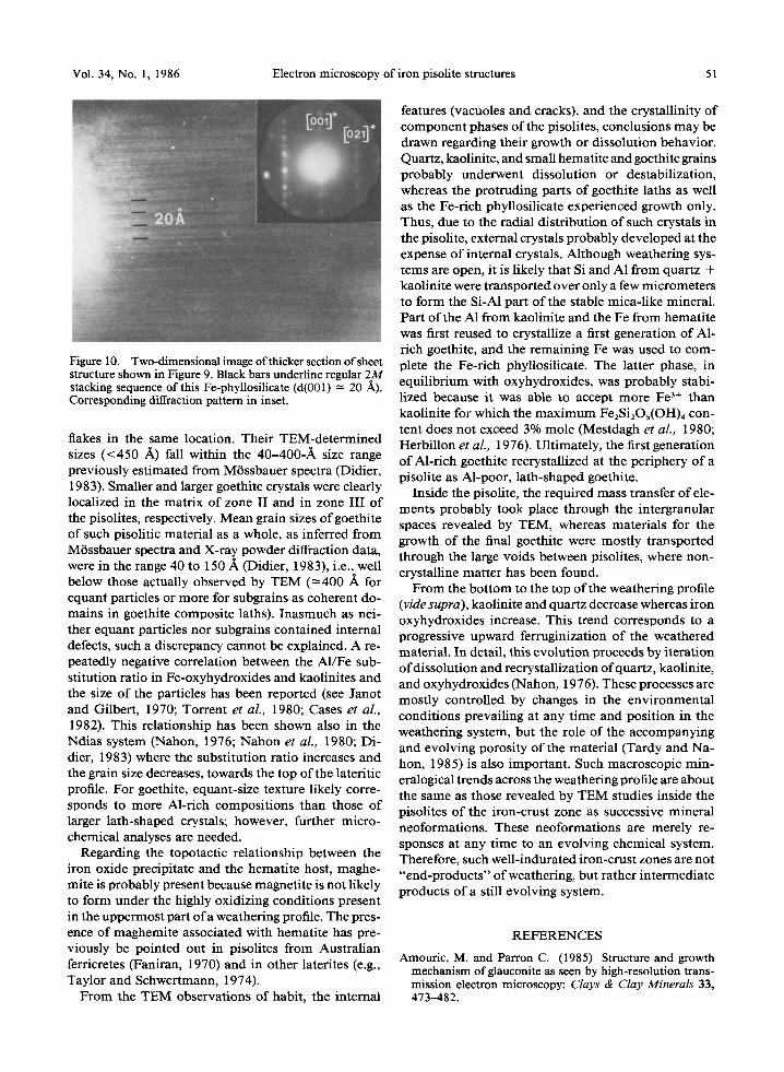
Commonly grouped as packets in the goethite matrix of zone III are platelets of a layered mineral (Figure 8a). Qualitative microanalyses of such platelets (Figure 8b) revealed chiefly Fe with minor Si and A1 and locally traces of P, but no alkali elements. The HRTEM lattice image in Figure 9 shows a regular 10.2-~k basal spacing. Moreover, when two-dimensional lattice images could be recorded on this electron-beam sensitive phase (Fig- ure 10), a two-layer superstructure (2M polytype) was
b
s F t E
c
om 1.a~ ++am +.ore ~ c w 5+too e+mm 7+cm l+.am ++oc+ m~,c
ENERGY (k~V~
Figure 8. (a) Concentration of platelets of a layered mineral in zone III, as shown by arrow heads. (b) Qualitative micro- chemical analysis of such platelets (Cu and Zn are due to specimen stage).
identified. Both chemical and structural data suggest a mica-like, Fe-rich, alkali-poor phyllosilicate. This ma- terial is similar to a mineral not fully identified by Jefferson et al. (1975) in an HRTEM study ofkaolinites which were iron-stained by goethite.
DISCUSSION AND CONCLUSION
Two contrasting size ranges were found for both he- matite and goethite. Small hematite grains from the pisolitic core were much more numerous than larger
Figure 7. Mosaic of rounded quartz grains in pisolite. Black arrows show fine pores between grains and white arrows in- dicate dislocation walls between subgrains.
Figure 9. Platelet of well-organized layered mineral showing regular 10.2-/k fringes and large and poorly contrasted ka- olinite area (d(001) -~ 7.3 A).
Vol. 34, No. 1, 1986 Electron microscopy of iron pisolite structures 51
Figure 10. Two-dimensional image of thicker section of sheet structure shown in Figure 9. Black bars underline regular 2M stacking sequence of this Fe-phyllosilicate (d(001) -~ 20 A). Corresponding diffraction pattern in inset.
flakes in the same location. Their TEM-determined sizes (<450 A) fall within the 40-400-/k size range previously est imated from M6ssbauer spectra (Didier, 1983). Smaller and larger goethite crystals were clearly localized in the matr ix of zone II and in zone III of the pisolites, respectively. Mean grain sizes ofgoethi te of such pisolitic material as a whole, as inferred from Mrssbauer spectra and X-ray powder diffraction data, were in the range 40 to 150/~ (Didier, 1983), i.e., well below those actually observed by TEM (=400 ~, for equant particles or more for subgrains as coherent do- mains in goethite composite laths). Inasmuch as nei- ther equant particles nor subgrains contained internal defects, such a discrepancy cannot be explained. A re- peatedly negative correlation between the A1/Fe sub- stitution ratio in Fe-oxyhydroxides and kaolinites and the size of the particles has been reported (see Janot and Gilbert, 1970; Torrent et al., 1980; Cases et al., 1982). This relationship has been shown also in the Ndias system (Nahon, 1976; Nahon et al., 1980; Di- dier, 1983) where the substitution ratio increases and the grain size decreases, towards the top of the lateritic profile. For goethite, equant-size texture likely corre- sponds to more Al-rich composi t ions than those of larger lath-shaped crystals; however, further micro- chemical analyses are needed.
Regarding the topotactic relationship between the iron oxide precipitate and the hemati te host, maghe- mite is probably present because magnetite is not likely to form under the highly oxidizing conditions present in the uppermost part of a weathering profile. The pres- ence of maghemite associated with hemati te has pre- viously be pointed out in pisolites from Austral ian ferricretes (Faniran, 1970) and in other laterites (e.g., Taylor and Schwertmann, 1974).
F rom the TEM observations of habit, the internal
features (vacuoles and cracks), and the crystallinity of component phases of the pisolites, conclusions may be drawn regarding their growth or dissolution behavior. Quartz, kaolinite, and small hematite and goethite grains probably underwent dissolution or destabilization, whereas the protruding parts of goethite laths as well as the Fe-rich phyllosilicate experienced growth only. Thus, due to the radial distr ibution of such crystals in the pisolite, external crystals probably developed at the expense o f internal crystals. Although weathering sys- tems are open, it is likely that Si and A1 from quartz + kaolinite were t ransported over only a few micrometers to form the Si-A1 part of the stable mica-l ike mineral. Part of the A1 from kaolinite and the Fe from hemati te was first reused to crystallize a first generation o f A1- rich goethite, and the remaining Fe was used to com- plete the Fe-rich phyllosilicate. The latter phase, in equil ibrium with oxyhydroxides, was probably stabi- l ized because it was able to accept more Fe 3+ than kaolinite for which the max imum Fe2Si2Os(OH)4 con- tent does not exceed 3% mole (Mestdagh et al., 1980; Herbi l lon et aL, 1976). Ult imately, the first generation of Al-rich goethite recrystallized at the periphery of a pisolite as Al-poor, lath-shaped goethite.
Inside the pisolite, the required mass transfer of ele- ments probably took place through the intergranular spaces revealed by TEM, whereas materials for the growth of the final goethite were mostly t ransported through the large voids between pisolites, where non- crystalline mat ter has been found.
F rom the bo t tom to the top of the weathering profile (vide supra), kaolinite and quartz decrease whereas iron oxyhydroxides increase. This trend corresponds to a progressive upward ferruginization of the weathered material. In detail, this evolut ion proceeds by i terat ion of dissolution and recrystallization of quartz, kaolinite, and oxyhydroxides (Nahon, 1976). These processes are mostly controlled by changes in the environmental condit ions prevailing at any t ime and posi t ion in the weathering system, but the role of the accompanying and evolving porosi ty of the material (Tardy and Na- hon, 1985) is also important . Such macroscopic min- eralogical trends across the weathering profile are about the same as those revealed by TEM studies inside the pisolites o f the iron-crust zone as successive mineral neoformations. These neoformations are merely re- sponses at any t ime to an evolving chemical system. Therefore, such well- indurated iron-crust zones are not "end-products" of weathering, but rather intermediate products of a still evolving system.
REFERENCES
Amouric, M. and Patron C. (1985) Structure and growth mechanism of glauconite as seen by high-resolution trans- mission electron microscopy: Clays & Clay Minerals 33, 473--482.

52 Amouric, Baronnet, Nahon, and Didier Clays and Clay Minerals
Briiekner, W. (1952) The mantle rock ("laterite") of the Gold Coast and its origin: GeoL Rdsch. 43, 307-327.
Bursill, L. A. and Withers, R. L. (1979) On the multiple orientation relationships between hematite and magnetite: J. AppL Cryst. 12, 287-294.
Cases, J. M., Lietard, U., Yvon, J., and Delon, J. F. (1982) Etude des proprietes cristallochimiques, morphologiques et superficielles de kaolinites desordonnees: Bull. Mineral 105, 439-455.
Didier, P. (1983) Parageneses ~ oxydes et hydroxydes de fer dans les bauxites et les cuirasses ferrugineuses: These 3eme cycle, Universit6 de Poitiers, 150 pp.
Dixon, J. B., Golden, D. C., Calhoun, F. G., and Buseck, P. R. (1983) Synthetic aluminous goethite investigated by HRTEM: in Proc. 41st Annual Meeting Electron Micros- copy Soc. Amer., Phoenix, Arizona, J. W. Bailey, ed., San Francisco Press, San Francisco, 192-193.
Faniran, A. (1970) Maghemite in the Sydney duricrust: Amer. Miner. 55, 925-933.
Herbillon, A. J., Mestdagh, M. M., Vielvoye, L., and De- rouane, E. G. (1976) Iron in kaolinite with special ref- erences to kaolinite from tropical soils: Clay Miner. 2, 201- 219.
Janot, C. and Gilbert, H. (1970) Lesconstituantsduferdans certaines bauxites naturelles etudiees par effet MOssbauer: Bull. Soc. Fr. Min~r. Cristall. Paris 93, 213-223.
Jefferson, D. A., Tricker, M. J., and Winterbottom, P. A. (1975) Electron microscopic and Messbauer spectroscopic studies of iron-stained kaolinite minerals: Clays & Clay Minerals 23, 355-360.
Mestdagh, M. M., Herbillon, A. J., Rodrique, L., and Roux- her, P. G. (1982) Evaluation du r61e du fer structural sur la cristallinit6 des kaolinites: Bull. Mineral 105, 457-466.
Mestdagh, M. M., Vielvoye, L., and Herbillon, A. J. (1980) Iron in kaolinite: II. The relationship between kaolinite crystallinity and iron content: Clay Miner. 15, 1-13.
Nahon, D. (1976) Cuirasses ferrugineuses et encrofltements calcaires au Senegal occidental et en Mauritanie. Systemes 6volutifs: geochimie, structures, relais et coexistence: Sci. G(ol. M~m. Strasbourg 44, 1-232.
Nahon, D. (1985) Evolution of ferricretes in tropical land- scapes: in Rates of Chemical Weathering of Rocks and Minerals, W. Colman, ed., Academic Press, New York (in press).
Nahon, D., Carozzi, A. V., and Parron, C. (1980) Lateritic weathering as a possible mechanism for the generation of ferruginous ooids: J. Sedim. Petrol 50, 1287-1298.
Nahon, D., Janot, C., Karpoff, A. M., Paquet, H., and Tardy, Y. (1977) Mineralogy, petrography and structures of iron crust (ferricretes) developed on sandstones in the Western part of Senegal: Geoderma 19, 263-277.
Olives Banos, J., Amouric, M., De Fouquet, C., and Baronnet, A. (1983) Interlayering and interlayer slip in biotite as seen by HRTEM: Amer. Mineral 68, 754-758.
Schwertmann, U. (1984) The influence of aluminium on iron oxides: IX. Dissolution of Al-goethites in 6 M HCI: Clay Miner. 19, 9-19.
Tardy, Y. and Nahon, D. (1985) Stability of Al-goethite, Al-hematite and Fe 3§ in bauxites, ferricretes and laterites. An approach of the mechanism of the concretion formation. Amer. J. Sci. (in press).
Taylor, R. M. and Schwertmann, U. (1974) Maghemite in soils and its origin: I. Properties and observations of soil maghemite: Clay Miner. 10, 299-310.
Torrent, J., Schwertmann, U., and Schulze, D. G. (1980) Iron oxide mineralogy of some soils of two river terrace sequences in Spain: Geoderma 23, 191-208.
(Received 20 October 1984; accepted 20 May 1985; Ms. 1418)