electromagnetic transients in radio/micr ... - …jpier.org/pier/pier108/07.10070304.pdf ·...
TRANSCRIPT

Progress In Electromagnetics Research, Vol. 108, 101–130, 2010
ELECTROMAGNETIC TRANSIENTS IN RADIO/MICR-OWAVE BANDS AND SURGE PROTECTION DEVICES
C. Gomes
Centre of Excellence on Lightning Protection (CELP)Department of Electrical and Electronics EngineeringUniversiti Putra MalaysiaMalaysia
V. Cooray
Division for ElectricityUppsala UniversitySweden
Abstract—A comprehensive review has been done on the typesof electromagnetic transients that may affect low voltage electricalsystems. The paper discusses various characteristics of lightning,switching, nuclear and intentional microwave impulses giving specialattention to their impact on equipment and systems. The analysisshows that transients have a wide range of rise time, half peakwidth, action integral etc. with respect to both source and couplingmechanism. Hence, transient protection technology should be morespecific with regard to the capabilities of the protection devices.Furthermore, we discuss the components and techniques availablefor the protection of low voltage systems from lightning generatedelectrical transients and the adequacy of International Standards inaddressing the transient protection issues. The outcome of our analysisquestions the suitability of 8/20µs test current impulse in representingcharacteristics such as the time derivative and the energy contentof lightning impulses. The 10/350µs test current impulse betterrepresents the integrated effects of the energy content of impulsecomponent and long continuing current. A new waveform is requiredto be specified for testing the ability of protective devices to respondto the fast leading edges of subsequent strokes that may appear 100 sof millisecond after the preceding stroke. The test voltage waveform
Received 3 July 2010, Accepted 7 August 2010, Scheduled 10 September 2010Corresponding author: C. Gomes ([email protected]).

102 Gomes and Cooray
1.2/50µs should also be modified to evaluate the response of protectivedevices for fast leading edges of induced voltage transients. A surgeprotective device that is tested for lightning transients may not be ableto provide defense against other transients.
1. INTRODUCTION
The term surge is vaguely used with different meanings in the electricalengineering community thus, it is often misinterpreted by fellowresearchers in the literature. The most common usage of the termsurge is to identify “electrical transients”, which is the scope of thispaper.
An electromagnetic transient is a sharp increase in electromagneticenergy in space. Such electromagnetic transients in the kHz to MHzrange may induce voltages and consequently currents in an electricalsystem of which the duration can vary from nanosecond scale to fewmilliseconds. Such transients may be generated in or injected intopower supply, communication or any other system where electricity isinvolved in whatever the form and propagate along the same system todamage the system itself or any component connected to the system.The type and magnitude of the damage depends on the rate of rise,amplitude, duration, repetition etc. of the transient and the systemresponse.
This paper presents the available information on the characteris-tics of electromagnetic transients that may affect systems that conductelectrical signals (power and communication). The main purpose ofthis study is to discuss the capabilities of devices meant for lightningprotection, in providing defense for the equipment and systems againstother transients.
2. TYPES OF TRANSIENTS
There are several sources of transients.a. Direct Lightning: Lightning Electro-Magnetic Pulses (LEMPs)b. Indirect Lightning: Lightning Induced Voltage Impulses (LIVI)c. Voltage pulses due to ground potential rise: Step Potential Pulses
(SPP)d. Power system abnormally or Switching operations: Power System
Generated Transients (PSGT)e. Nuclear explosions: Nuclear Electro-Magnetic Pulses (NEMPs)f. High power electromagnetic emitters: High-Power Electro-
Magnetic pulses (HPEMs)
Progress In Electromagnetics Research, Vol. 108, 2010 103
g. Static electricity generated discharges: Electro-Static Discharges(ESD)Out of the above types of transients mentioned above, ESDs are
not of concern to the investigators on surge protective devices as thesource is most often very close to the victim (e.g., between IC chip andthe pins). Hence we do not discuss regarding ESD in this paper.
2.1. LEMPs
Lightning is one of the main destroyers of electrical and electronicsystems in many parts of the world. A significant amount of work hasbeen done to investigate the properties of ground lightning which is ofprime concern as far as system damage at ground level is concerned.
Lightning current at the channel base, in general, is doubleexponential in profile. Such currents are recorded either by tower-based measuring systems or in triggered lightning. Both methods havetheir own drawbacks; Currents in the tower base measurements areinfluenced by the presence of the tower and in triggered lightning, thecurrent of the first return stroke is totally different to its expectedcounterpart in natural lightning, due to the presence of the conductingwire through which the initial current flow.
In most of the recorded currents the initial impulse, which isin the microsecond scale, is followed by another current componentwhich is in the millisecond scale. This is popularly termed ascontinuing current which has amplitudes ranging from few tens toseveral hundreds of Amperes. They are either slow decaying rampsor plateaus followed by exponential decay, which last for few tensto several hundreds of milliseconds [1–4]. It is often observed thatthere are humps embedded in the continuing currents, termed Mcomponents. These almost symmetric swells have rise times of aboutfew hundred microseconds and amplitude ranging from few hundredsto about thousand Amperes [3, 5–10].
For the ease of analysis and testing purposes the two parts areseparately referred; the initial impulse current is called the short strokeand the slow continuing current is called the long stroke.
In the designing and testing of devices for protection againstlightning transients the important parameters are
a. The peak impulse current: This determines the voltage thatwill be developed along the current path due to the resistivecomponent of the impedance.
b. The rise time (usually given as the time between the 10% and 90%of the peak current): This is an important factor to determine themaximum response time of the SPD.

104 Gomes and Cooray
c. The time derivative of the rising part: The fastest part ofthe lightning current is in the rising edge, thus it has thehighest current derivative. It determines the voltage that willbe developed along the path due to the inductance component ofthe impedance. The current derivative also restrains the voltageinduced in nearby conducting loops due to magnetic coupling.
d. Half peak width of the impulse current: This parameter representsthe width of the pulse. A more appropriate representation is thezero-crossing time, however, due to the ambiguity in tracing thezero level this parameter may contain a large error.
e. Action integral (∫
i2 dt): This is the energy dissipated per unitresistance through which the lightning current flows.
Most of the above parameters are inter-related and have adependency on the charge brought down and channel conductivityduring each phase.
The Figure 1 depicts a typical channel base current waveform fora negative subsequent return stroke observed in a triggered lightningsession in China [8]. The figure also shows the 10%–90% rise time andhalf peak width. Note that the typical half value width measuredin other studies is one order greater than the same parameter inthis stroke. Figure 2(b) and Figure 3(a) show typical subsequentstroke current waveforms measured in triggered lightning session inFlorida, USA. It has been observed in several studies that the impulseduration of subsequent strokes tends to decrease with increase inamplitude [1, 8].
Figure 1. The channel base current waveform for a negativesubsequent return stroke observed in a triggered lightning session inChina [8]. The figure also shows the 10%– 90% rise time and half peakwidth.
Progress In Electromagnetics Research, Vol. 108, 2010 105
(a)
(b)
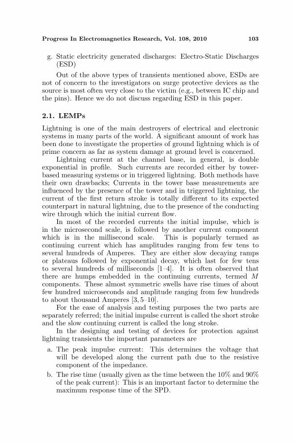
Figure 2. (a) The induced voltage at the centre of a 682m long linefor a triggered lightning subsequent stroke struck at 145 m away fromthe line, (b) the corresponding stroke current [16].
(a) (b)
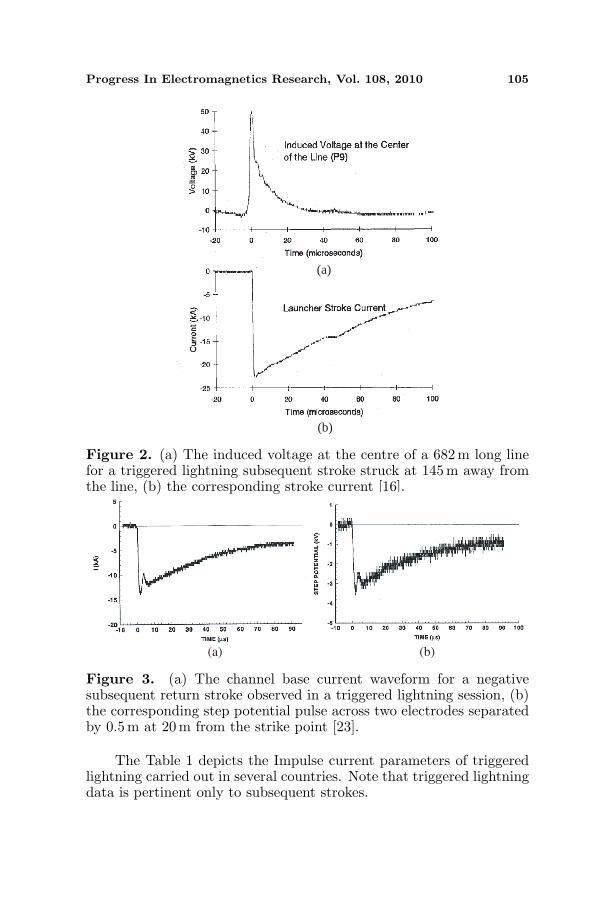
Figure 3. (a) The channel base current waveform for a negativesubsequent return stroke observed in a triggered lightning session, (b)the corresponding step potential pulse across two electrodes separatedby 0.5m at 20 m from the strike point [23].
The Table 1 depicts the Impulse current parameters of triggeredlightning carried out in several countries. Note that triggered lightningdata is pertinent only to subsequent strokes.

106 Gomes and Cooray
Table 1. Parameters of current waveforms pertinent to negativesubsequent strokes observed in triggered lightning experiments. Notethat rise time given is 10%–90% of the peak value except for a 30%–90%. b maximum value c less than 5% of the sample exceeds the value(extreme value) d less than 95% of the sample exceeds the value.
Reference
Impulse current (Short stroke)
Amplitude
(kA)
di/dt
(kA/µs)
Rise
time
(µs)
Half peak
width
(µs)
Charge
(C)
∫i2 dt
(kJ/Ω)
Mean Max Min
[9] 11.9 21.0 6.6 0.8a 39
[8] 17.6 41.6 6.6 2.6 30.7
[1] 33 44 22 195b 0.25 1.35 2.3 4.5
[7] 12 29c 4.7d 28 0.37 18 2.5 3.5
[10] 9.9 49 4.5.9 37.1 1.14 4.7
In general the impulse current of subsequent strokes show thefollowing characteristics.
a. The peak value is few tens of kilo Amperes,b. The derivative in the rising edge is few tens of kilo Amperes per
micro secondc. The rise time is in the order of one micro secondd. The half peak width is few tens of microsecondse. The action integral (energy per unit resistance) is few kilo Jules
per OhmThe IEC 62305-1 (2006) have made their recommendations for
testing based on the current measurements done by [11] and [12].The values given for each discharge event as per this tower basedmeasurements is as given in Table 2 below.
Note that the values pertinent to the negative subsequentstrokes of tower based measurements, in general, are in agreementwith those pertinent to the negative subsequent strokes of triggeredlightning measurements (although some parameters cannot be directlycompared).
Henceforth, we adhere to the following reference, unless otherwisestated.
If less than 5% of the sample exceeds a certain value we call it the“extreme value”; and if less than 50% of the sample exceeds a certainvalue we call it the “representative value”.

Progress In Electromagnetics Research, Vol. 108, 2010 107
Table 2. Parameters of current waveforms pertinent to negative andpositive lightning according to the measurements of [11] and [12] basedon tower measurements. The information was consequently adaptedby IEC Standards. Note that rise time given is 10%–90% of thepeak value. The values of parameters other than those of the currentamplitude are the representative values (50%). a less than 80% b lessthan 98%. Note that there is no information on positive subsequentstrokes. This is due to the rarity of multiple stroked positive lightning(less than 1% of the positive lightning is multiple stroked).
Discharge
Event
Impulse current (Short stroke)
Amplitude
(kA)
Max
di/dt
(kA/µs)
Rise
time
(µs)
Total
stroke
duration
(µs)
Charge
(∫
i dt)
(C)
Specific
Energy∫i2 dt
(kJ/Ω )
50% 5% 95%
Negative
first
stroke
20a 90 4b 24,3 5,5 75 4,5 55
Negative
subsequent
stroke
11,8 28,6 4,9 39,9 1,1 32 0,95 6
Positive
stroke35 4,6 250 2,4 22 230 16 650
2.2. LIVI
A lightning may induce voltage impulses in the conductors in thevicinity due to electromagnetic coupling. The amplitude and the profileof such voltage impulses depends on the peak value and peak timederivative of the lightning impulse current, proximity to the lightning,ground conductivity (propagation effects), length of the conductingline exposed, its orientation and termination, height of the line abovethe ground, branches of the line between the generation point and thevictim etc. [13–17].
As it was reported by [14], in an isolated small house, the inducedvoltages in a de-energized power line (which is decoupled from theexternal supply) exceeded 100 V for a ground flash that struck 24 kmaway. The rise time of the induced voltage was typically less thana microsecond and the individual pulse width was typically a fewmicroseconds. Several triggered lightning studies reveal that even at
108 Gomes and Cooray
very close range the pulse profile is similar. As per [16] at 145 m froma 682 m line the 10%–90% rise time and half value width of inducedvoltages for negative subsequent strokes have representative values1.6µs and 4.1µs respectively. In the same study the investigators haverecorded that the peak induced voltage varies from 8 kV to 100 kV forpeak lightning current that ranges from 4 kA to 40 kA. Figure 2 depictsthe induced voltage and the corresponding channel base current fora negative subsequent stroke [16]. The studies on both natural andtriggered lightning by [17] show that the voltage induced in a 500 mlong cable about few tens of meters (asymmetric locations) is in therange of few 10 s to few hundreds of kV with rise time and pulse widthof fraction of a microsecond and few microseconds respectively. Similarexperimental results have also been given in [18].
The theoretical work done by [19] and [20] reveals that the voltagesinduced at the midpoint of an isolated transmission line of length about680m, is nearly double exponential for near lightning. For lightningstrikes at 40 m symmetrically away from the line, the induced voltagehas a peak value of about 120 kV and the 10%–90% rise time is in theorder of 0.1µs. As the point of strike moves to 400 m away from theline, the peak reduces to about 50 kA and the rise time increases to by2 to 3 times the value at 50 m.
These voltage pulses give rise to current waveforms which dependon the characteristic impedance of the path along which they travel.The rise time of such current waveforms cannot be much different fromthat of the induced voltage waveforms unless the current travels a longdistance along the line so that the high frequency components willundergo selective attenuation [21].
The interaction of cloud lightning and discharge events of groundlightning that occur at cloud level has not been studied much inthe literature. Bursts of electromagnetic pulses, pertinent to suchcloud level events, have been observed at ground level [22]. It maybe of interest to investigate how such pulse trains interfere withvery low voltage (VLV) data transmission systems. Several studiesreported in [22] show that in preliminary breakdown pulses (pulsetrains that precede return strokes) recorded in Sweden and Denmarkthe maximum pulse amplitude is several times greater than that of thesucceeding return stroke (such observation is not made in the PBPsmeasured in tropics). As it was observed in [14] the induced voltagesdue to such cloud flashes have amplitudes comparable with that ofreturn stroke generated voltages pertinent to cloud to ground flashes(around 10–20 km away from the measuring site). However, one couldexpect the amplitudes of voltages induced by ground flashes to be muchgreater as the ground strike location reaches close range to the point

Progress In Electromagnetics Research, Vol. 108, 2010 109
of observation (as the cloud flashes cannot be very close due to theheight).
2.3. SPP
In the event of a ground lightning strike, the potential at the point ofstrike is raised to a very high value and decreases radially outwards.This is termed the Ground Potential Rise (GPR). The potentialdifference between two points in the proximity is called the steppotential. In time domain the step potential at a given location (twoclose points) will be a transient for a lightning strike which we willrefer as the Step potential Pulse (SPP).
The studies on triggered lightning by [23] reveal that SPP is almostidentical in wave profile to the corresponding return stroke current atthe channel base. Thus, the peak value of the SPP and the peak ofthe return stroke current shows a linear relationship. Figure 3 showsa return stroke current waveform of a triggered lightning (Figure 3(a))and the corresponding step potential pulse (Figure 3(b)) across twoelectrodes separated by 0.5 m at 20 m from the strike point.
Theoretically, for a uniform hemispherical mass of earth aroundthe point of strike the peak of the SPP should decrease following inversesquare law (for a step distance much smaller than the radial distanceto the point of concern). However, as per the limited data available(only at 10 m and 20 m), the study [23] observes that the relation isinverse distance, instead of inverse square distance. Understandably,they explained the discrepancy as due to the limited skin depth atlightning frequency spectrum.
The data given in [23] shows that for a current in the range of20 kA the peak SSP is about 10 kV/m over soil of resistivity about500Ωm (the measurement has been done for two points separated by0.5m). With the correlations that they have observed, there can beSPPs in the order of 5 kV/m at 100 m from the strike for return strokesof currents exceeding 100 kA.
2.4. PSGT
Power system generated transients (sometimes generally calledswitching impulses, although they are only a sub-set of PSGTs) aredue to various operations and accidents. Following are some causes ofgenerating SI.
a. Switching on/off large inductive and capacitive loads or re-energizing of power systems.

110 Gomes and Cooray
b. Arcing in the power system due to over voltages, transformerfailures, grid switching etc.
c. Short circuiting at various stages of power distributionUnlike LEMPs which are always externally generated, PSGTs can
be generated either inside or outside of a given installation.The profile and magnitude of a PSGT depends on both the source
of generation and the path propagation from the point of observationto the source. The waveforms can have the shapes of ringing, doubleexponential, bi-polar or even chaotic. The damage that a switchingimpulse may cause depends on the steepness of the rising and fallingedges, amplitude and the duration (energy content).
Most of the switching type PSGTs are oscillatory in nature. Anoscillatory transient is an abrupt, non-power frequency change in thesteady state condition of voltage, current, or both, that includes bothpositive and negative polarity values. The instantaneous value ofcurrent and voltage of such transient changes polarity rapidly.
The characteristic of an oscillatory transient is described by itsspectral content (predominant frequency), duration, and magnitude.The predominant frequency of an oscillatory transient may reach ashigh as 500 kHz [24, 25]. Figure 4 shows an oscillatory transientgenerated in a 34.5 kV system when a capacitor bank is energized [24].The transient can be passed into LV system mainly through magneticcoupling at the substations; even capacitive coupling and resistivecoupling (due to insulation failure) is possible.
Current (A)
Time (ms)
Figure 4. Oscillatory transient generated in a 34.5 kV system when acapacitor bank is energized [24].

Progress In Electromagnetics Research, Vol. 108, 2010 111
2.5. NEMP
The highly energetic Gamma rays (higher order MeV to GeV) releasedin a nuclear explosion will cause Compton scattering of the atmosphericmolecules, thus a stream of law mass electrons will move awayfrom the epicenter of explosion leaving behind the heavy positiveirons. The moving charge will generate electromagnetic fields andalso interact with ambient fields creating electromagnetic impulses [26–28]. The NEMPs generated by explosions occurring at high altitudesare also referred as High-altitude ElectroMagnetic Pulses (HEMPs).Henceforth, in most of the cases the transients that we refer as NEMPsare the HEMPs.
NEMPs that are generated by a nuclear explosion will havenanosecond scale pulse widths and rise times. The amplitude canexceed 60 kV/m, at locations directly under the explosion. Dependingon the height and strength of the explosion, NEMPS may inducevoltage pulses that are harmful to electronics within a radius of 500 km–800 km where the centre is taken as the point directly underneath theexplosion [29, 30].
NEMPs are much faster pulses than LEMPs therefore; specialdefenses are needed in shielding the systems from them. The study [31]discussed in detail the behavior of different media for the penetrationand transmission of NEMPs. The low frequency components ofNEMPs will also be able to induce large currents and voltages inthe long-distance communication and data lines. Unfortunately,many available scientific work on NEMPs do not reveal the actualcharacteristics of electromagnetic pulses, instead the studies at presentare more inclined towards the aspects of defense and political riskassessment [32].
Over the years many theoretical studies have been done toinvestigate the similarities and differences of the interaction of LEMPsand NEMPs [30, 33, 34]. In many of these studies the comparison isdone between NEMPs at long distance which are essentially planewaves (for small systems) and LEMPs at very short range (few metersto several tens meters away) of which the amplitude is inverselyproportional to the distance. Studies done in [35] argue that due to themuch higher rate of rise and higher peak of the NEMPs the inducedeffects of NEMPs should always be greater than that due to very nearlightning; unless the lightning current is exceptionally high (such as insuper bolts). By analyzing the Fourier spectra of LEMPs and NEMPs,the investigation described in [34] showed that at several frequencyranges the average lightning may cause more harmful induced voltagesin small objects (such as aircrafts) than that is done by NEMPs. Theyjustified their argument with information given in [36].
112 Gomes and Cooray
The study [33] showed that the comparison of the induced effectsof LEMPs and NEMPs is much more complicated than that has beendone in previous studies. Although the rate of change of electricfield pertinent to subsequent strokes of triggered lightning is somewhatsimilar to that of NEMPs, the nonlinear response to NEMPs may notbe the same as the nonlinear response to LEMPs. Furthermore, due tothe large areas exposed to a NEMP (systems such as power grids andcommunication networks), the entire network may be stressed almostsimultaneously. Also, in contrast to the event of a lightning, in theevent of a nuclear explosion, an entire fleet of military aircrafts, ships,and missiles can be simultaneously exposed to NEMPs.
The most convincing information on the differences betweenLEMPs and NEMPs is given in [37]. This information is pertinentto experimental data on lightning to (or near) aircrafts and simulatedexperiments on the interaction of same aircrafts with NEMPs. It hasbeen revealed that the rate of change of magnetic flux density on thesurface of the aircraft and the total normal current density are 3750 T/sand 20A/m2 for LEMPs and 40 000 T/s 90 A/m2 for the NEMPs. Thedata clearly indicates that there is a marked difference between NEMPsand LEMPs.
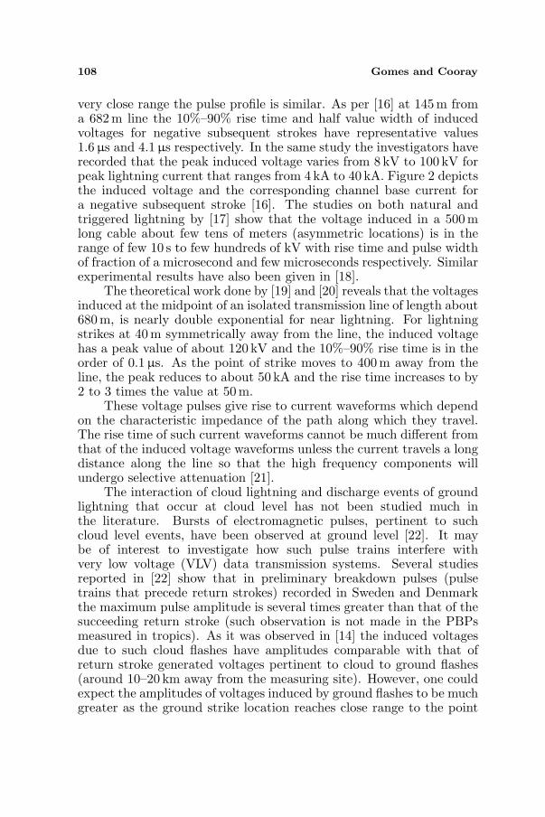
NEMPs are most often simulated as double exponentialwaveforms. Figure 5 depicts a typical waveform that is commonlyused to represent NEMPs [38].
Normalized Amplitude
Time (ms)
Figure 5. Waveform that is commonly used to represent NEMPs andthe relevant parameters [38].

Progress In Electromagnetics Research, Vol. 108, 2010 113
2.6. HPEM
Microwave sources may generate electromagnetic pulses in the GHzrange that may induce voltages in electronics that can severely affecttheir performance. Such microwave emission may most often beintentional (for warfare, sabotage etc.) or sometimes be unintentional(due to unawareness, stubbornness or negligence). The investigationson HPEM were accelerated during the mid-90 s due to the predictionof greater usage of EM warfare. Although, not as comprehensive asone would expect, a considerable amount of information is availablenow on the public domain, in this regard, based on the work done forthe last few years [39–43].
Basically the intentional microwave emission is classified intotwo categories. They are high-power microwaves (HPM) which arecontinuous high-energy signals of narrow bandwidth and variablecenter frequency, and Ultra-Wide Band (UWB) pulses which cover abroad frequency spectrum due to their fast rise times in the pico-secondrange and short pulse durations of a few nanoseconds. However, HPEMcan be generated in several other forms as well [44].
Due to the large bandwidth UWB pulses have a higher chanceof interacting with electronics, hence under studies on IntentionalElectroMagnetic Interference (IEMI), UWB pulses are investigatedwith greater interest [45–48].
A voltage test waveform that represents a UWB pulse is givenin Figure 6(a) (adopted from [46]). Due to the very high frequencycontent UWB pulses are attenuated significantly as they propagatealong transmission lines. Figure 6(b) depicts the variation of the UWBpulse (shown in Figure 6(a)) at different lengths of the cable alongwhich it propagates. Note that with the distance of propagation thepulse amplitude is significantly reduced while the rise time and pulsewidth increases.
The study [49] discussed the urgent need of developing specificstandards on HPEM. IEC Standard 61000-2-13 Ed. 1, 2005 [50]provides some comprehensive information on radiated and conductedeffects of HPEM.
3. PROTECTION SCENARIO AGAINST TRANSIENTS
In this section, we discuss in details the protection methodologyof equipment against the electromagnetic transients using SurgeProtective Devices (SPDs). The transient protection of LV systemsis done basically with one-port SPDs which are connected in shunt(phases to neutral and neutral to ground or phases and neutral toground). In a coordinated SPD system the wire length from one SPD to

114 Gomes and Cooray
Voltage (V)
Voltage (V)
2
Time (ns)
300
250
200
150
100
50
0
3 4 5 6 7
450
400
350
300
250
200
150
100
50
0
After 1 m propagation
After 2 m propagatio n
After 4 m propagation
After 6 m propagation
After 8 m propagation
7Time (ns)
3 4 5 6
(a)
(b)
Figure 6. (a) A voltage test waveform that represents a UWB pulse.This pulse has a rise time in the order of 100 ps and a pulse width(FWHM) of about 1 ns. (b) The attenuation of the UWB pulse shownin igure-5 as the pulse propagates along the cable (adopted from [43]).
the other will provide the impedance (mostly in the form of inductance)to reduce steepness of the induced voltage waveform. In some devices,a coil has been inserted in between two parallel SPDs (en bloc) tosimulate the inductance (together with parallel capacitors). These aresometimes called surge filters. It has been observed that in severalproducts a non linear resistor (e.g., PTCR) has also been inserted inseries with the power line (in between the two parallel SPDs) to absorba part of the energy.

Progress In Electromagnetics Research, Vol. 108, 2010 115
Basically, the main purpose of a SPD, irrespective of the wiringsystem (TNS, TNC, TNC-S and TT), is to divert both differentialmode and common mode (not applicable to TNC) transients to ground.In TT system another important application is to equipotentialize(more accurately stating; to reduce the potential difference belowhazardous level) the ground, neutral and phases in the event of a GPR.
In the event of current diversion, the downstream equipmentwill experience both common mode and differential mode transientpotential differences due to the inherent impedance of the SPDs in theoperational-mode and also due to the lengths of wire along which thetransient travel wire lengths. In practice although the operation-modeimpedance of a SPD is very small, due to the large amplitude and timederivative of transient currents, peak potential differences in the orderof 1–2 kV is very common in most of the SPDs for transient currentsof few tens of kilo Amperes. This is termed the “residual voltage” inthe literature.
In a TT system, as the SPD between ground and neutralapproaches low impedance mode, a current may flow from the groundof the utility to the transformer ground which is at a different potential(through the SPD). This will induce a voltage across the equipmentground and the neutral which will not be that high due to the longlength of neutral wire from the utility to the transformer.
The following factors of SPDs are of prime importance in theprotection of equipment
a. The peak transient current that the SPD can handleb. The energy per resistance (action integral) and the charge that
the SPD can withstandc. The number of sequential transients that will be withstood by the
SPDd. How fast the SPD can respond to a transiente. The magnitude of the residual voltage that will be encountered by
the downstream equipmentf. The magnitude of the leakage current through the shut SPD, when
the SPD is in non-operational modeg. In a low power quality situation; the maximum sustained over
voltage (at operational frequency) under which the SPD willremain non-operational (high impedance mode).
To address these requirements the standards introduce severalprotection zones to the protection strategy. They are termed,
a. Zone-1: The SPDs that will encounter direct lightning currents,induced voltage transients and SPPs.

116 Gomes and Cooray
b. Zone-2: The SPDs that will encounter induced voltages and let-through voltages of protectors in the Zone-1
c. Zone-3: the SPDs that will encounter induced voltages and let-through voltages of protectors in the Zone-2It should be noted that SPDs which are meant to be at Zone-2 or
3 may subject to direct lightning currents and SPPs due to incorrectengineering practices (examples: Taking an outdoor power feeder linefrom an undesired point or haphazardly grounding more than one pointof a given power network).
In the commercial literature, one may find the term “Currentarrester” used for Zone-1 protectors and the term “Surge arrester”used for Zone-2 & 3 arresters.
In the manufacture’s brochures, one can find a large number ofclassifications of surge protective devices based on various factors.(e.g., zone of application, impulse current rating, technology, mountingmethod etc.). In the scientific literature, SPDs are basically, dividedinto two categories, depending on their temporal response to atransient,
a. Voltage Switching Type or Crowbar type: The device undergoesan abrupt change from high impedance to low impedance at acertain value of the transient (e.g., Spark gaps, gas dischargetubes, thyristors, triacs etc.)
b. Voltage limiting type or Clamping Type: the device undergoessomewhat continuous change from high impedance to lowimpedance with the increment of the transient (Metal OxideVaristors, zener diodes etc.)Each of the above categories has its own advantages and
drawbacks with respect to the response time, current handlingcapacity, let through voltage, leakage current and follow currentetc. While attempts are made to improve each type of componentindividually, in the last few decades, SPDs are also made by cascadingdifferent types of components s, in order to compensate for thedrawback of one type. Such devices are termed hybrid systems. Severalsuch hybrid SPDs are available commercially. However, in the caseof combining several components it will be very significant to have aproper coordination to avoid one component being overstressed.
4. TEST WAVEFORMS
As per the Section 2, apart from some switching impulses, most of thetransients can be represented by a double exponential waveform withvarious decay constants. The Figure 7 depicts the basic waveform

Progress In Electromagnetics Research, Vol. 108, 2010 117
Figure 7. The basic waveform given in [1] to represent the lightningcurrent.
given in [51] to represent the lightning current. The time T1 is arepresentative value for the rise time of the waveform. The time T2
represents the half peak width of the waveform. The values of T1 andT2 distinguish one test waveform from the other.
4.1. 10/350 µs Current Waveform
The current of first return stroke in a cloud-to-ground lightning willbe represented by a waveform where T1 and T2 are 10µs and 350µsrespectively (Figure 7). This is termed the 10/350µs waveform.
A qualitative investigation on the available scientific data showsthat the representative value of rise time of the negative first strokeand the positive stoke are approximately 50% and 200% respectivelyof T1. Taking the large variation of lightning current waveforms intoaccount, one may conclude that 10/350µs test waveform is not a badrepresentation for both types of ground flashes.
Assuming that the half peak width of lightning current isapproximately 50% of the total flash duration, one can see that thetime T2 is one order larger than the average half peak width of negativefirst strokes and 3 times higher than that of positive strokes. As perthe data of [11] and [12], less than 5% of the negative flashes have totalduration exceeding 200µs. The same figure for the positive flashes is2000µs. According to these values, as far as only negative groundflashes are considered, apparently the 10/350µs waveform seems to beunnecessarily long in duration. However, considered (a) the energyof long stroke is also included in the waveform and (b) the waveformcovers a majority of the positive ground lightning, the parameter T2 is
118 Gomes and Cooray
reasonable to represent the first stroke current. The waveform has highsignificance for the testing of SPDs meant for the regions where positivelightning density is high. For the information of the reader, in somethunderstorms in Europe and winter storms in Japan the percentageof positive lightning (out of all ground lightning) is as high as 35%–40% [21, 52]. The long term data from lightning detection in Swedenshows that about 12% of the ground flashes are positive [53]. On theother hand, in tropics the same percentage is less than about 3% [22].Note that IEEE/ANSI Standards do not recommend the testing ofSPDs for 10/350µs waveform [54].
The amplitude of the current test waveform is to be determinedby the manufacturer as per the withstanding capability of the product.As per the data of [11] and [12] less than 5% of the negative flasheshave peak current exceeding 90 kA. The same figure for the positiveflashes is 250 kA.
When lightning strikes a power line, the current will travelin opposite directions in the line, with each component havingapproximately half the original peak. Consider an overhead systemthat has no branches of an overhead wiring system between the strikepoint and the power entrance to the utility of concern. Thus, a 100 kAstrike to the phase wire will deliver 50 kA to the utility power entrancein a case that there are no arcing between the lines.
For the 10/350µs impulse with 50 kA peak value, we get theapproximate values of the charge and the specific energy (actionintegral) as 25 C and 1.3 MJ Ω−1 respectively.
The charge of the above waveform covers 50% (as only half thecurrent flows towards the utility) of the extreme value of charge in thefirst negative ground strokes (excluding the long continuing part) andrepresentative values of charge in positive ground strokes but 3 timesless than the 50% of extreme value [11, 12].
The action integral of the above 10/350µs waveform is more than4 times of the 50% of both the extreme values of action integral in thenegative first stroke and the representative value of that of positivestrokes [11, 12]. The 50% of the extreme values of the action integral ofpositive strokes is about 5 times greater than the above value pertinentto a 10/350µs waveform with 50 kA peak value [11, 12].
The branching of current at the nodal points, the partialdischarges, the inter-line and side arcing and leakage through inductiveand capacitive coupling will even reduce the peak current thatapproaches the entrance of a utility once a 100 kA strike hits a randompoint of a LV power line.

Progress In Electromagnetics Research, Vol. 108, 2010 119
4.2. 8/20 µs Current Waveform
As per the IEC standards SPDs at both Zone-1 & Zone-2 should betested for the 8/20µs waveform [54, 55]. In this wave form the profileis similar to that is given in Figure 1 with T1 having a value of 8µsand T2 a value of 20µs. As per the IEC standards the waveformsimulates the current that will be resulted by induced voltages dueto nearby lightning. As per [54] the same waveform represents thedirectly injected lightning current.
The information presented in Section 2 reveals that as per thevoltages induced in cables at lightning at close range, recorded withhigh resolution measuring devices in the recent years, the rise timeis a fraction of a microsecond and the width is few microseconds.If we assume that the current due to induced voltage also have thesame wave profile, the 8/20µs current impulse hardly represents therise time of the actual negative subsequent strokes, unless a suitabledecoupling inductance is introduced between the source and the SPD.The pulse width is reasonable as it covers a large range of lightninginduced voltage waveforms.
For the Zone-1 protectors it is meaningless to conduct the testingfor both 10/350µs and 8/20µs as once the device passes the test withthe first waveform it will be totally immune to the second waveform.
As a waveform representing the injected lightning current, 8/20µswaveform only represent negative subsequent strokes and totallybeyond the characteristics of positive strokes.
4.3. 1.2/50 µs Voltage Waveform
The 1.2/50µs voltage waveform has a profile similar to that is givenin Figure 7 with T1 and T2 are 1.2µs and 50µs respectively. Thiswaveform has been recommended in IEC standards to test the spark-over voltage of arresters that include crowbar type SPDs (at Zone-1and 2). The spark-over voltage indicates the voltage at which thedevice impedance changes from a very high value to a very low valuein the presence of a fast increasing wave front.
The spark over voltage of a SPD strongly depends on the rate ofrise or the rise time. Therefore, in order to ensure that the protecteddownstream equipment is not subjected to a large voltage, the testwaveform should have a rise time that resembles the rise time ofinduced voltages due to lightning. As per the information presentedin the study, the rise time of the induced voltages due to subsequentstrokes of close lightning, is about one order less. The rise time ofNEMPs and HEMPs is about two orders less than that of the testwaveform. Hence, the suitability of this waveform to assess the spark

120 Gomes and Cooray
over voltage of SPDs is somewhat questionable.Zone-3 protectors supposed to be tested for a waveform which
shows 1.2/50µs profile for open circuit voltage and 8/20µs profile forshort circuit current. This is termed the combinational waveform whichserves the assessing of both spark-over voltage and let-through voltageat the same time. The argument against the applications discussedabove applies for this case as well.
4.4. Other Waveforms
The IEC Standards [51] describes a double exponential currentwaveform specified as 0.25/100µs to represent subsequent returnstrokes (of which T1 is 0.25µs and T2 is 100µs). However, the waveformis not exclusively recommended to test the SPDs, citing “If SPDs arespecified for the first short stroke threat, the subsequent short strokescause no additional problems. If inductances are used as decouplingelements, the higher current steepness facilitates coordination betweenSPDs”.
We would like to pay the attention to the following twoobservations on multi-stroked lightning.
a. More than 50% of the multi-stroked lightning have multiple strikepoints at ground (strokes of the same flash hit more than oneground point) [56, 57];
b. The inter-stroke interval can exceed even 500ms in someflashes [58, 59],
The first observation shows that a Zone-1 SPD can be subjectedto a subsequent stroke without being exposed to the first stroke. Thesecond observation reveals that there is a possibility of a Zone-1 SPDswitching back to high impedance mode before the occurrence of thesubsequent stroke. Thus, in both cases it is evident that the Zone-1SPDs have a certain risk of exposing to subsequent strokes while theyare in the high impedance mode. Therefore, the chances of the SPDsresponding late to the impulse have a certain probability.
The IEC Standards [51] introduces a nearly rectangular waveformto represent the continuing current (long stroke) where the pulse widthat 10% (Tlong) is 500ms. Note that the long stroke need not beconsidered for coordination purposes, thus it is insignificant for SPDsother than those at Zone-1. For Zone-1 SPDs, the additional stressfactor, due to the charge and action integral, that is in cooperated withthe long stroke is taken care of by the 10/350µs waveform. Thereforethe long stroke waveform also is not recommended exclusively for thetesting of SPDs.

Progress In Electromagnetics Research, Vol. 108, 2010 121
5. DISCUSSION
A wide range of electromagnetic transients has been discussed inthis paper. It is evident that depending on the source and couplingmechanism the total energy, average power and maximum transfer ofpower into a vulnerable system varies considerably. For the engineeringconvenience these effects are attributed to the rise time, maximumcurrent derivative, peak of the impulse, half peak width, actionintegral, bandwidth etc.
As it was discussed the spectrums of these parameters have awide range over different transients and even within the same type,especially in the cases of PSGTs and HPEMs. Hence it is evident thata surge protective device developed for the defense against one type oftransient may not be effective against other types.
The analysis that we have conducted on marketing promotionalbrochures, shows that there are several surge protectors are introducedwith the tag “all purpose transient protectors” or “wide spectrumtransient protectors”. These marketing promotional cataloguesvaguely state that the product can protect equipment from all knowntransient ranging from NEMPs to sub cycle switching impulses.However such an all purpose protector should;
a. have a response time of less than about one nanosecondb. be able to withstand impulse peak currents of over 100 kAc. be able to handle large energy components that spread over few
nanoseconds to several millisecondsd. be able to handle charge in the order of several coulombs
It is highly unlikely that any of the products that we have comeacross possess or tested for all the above characteristics. Instead,more than 90% of these products are tested only for the currentwaveforms 8/20µs and 10/350µs and voltage waveform 1.2/50µs.These waveforms are basically specified to test the protective devicesthat are designed to safeguard equipment against lightning transients.
The electrical system and related equipment of a LV systemmay be subjected to a number of transients from various sources.However, the general trend of the commercial and industrial sectoris to concentrate on lightning related transients in the case of surgeprotection. The IEC Standard 62305 (2006) series and related testingstandards are based on the protection against lightning transients. Theinformation given in this paper clearly shows that SPDs tested forlightning transients may capable of handling the energy content andcharge of other transients such as NEMPs and HPEMs however, therise time of the standard test impulses is much longer than that of
122 Gomes and Cooray
these pulses. The lightning test impulses also do not represent therepeated stresses applied by mostly oscillatory switching transients.
Lightning transients that may affect electrical systems can beclassified as follows based on the impulse characteristics.
a. First negative stroke,b. Subsequent negative strokec. Positive stroked. Continuing current and M component
In a properly designed and installed surge protection system SPDsonly in Zone-1 are exposed to direct lightning currents. Therefore, onlyZone-1 SPDs are needed to be tested for direct current impulses. Ina TT wiring system it should be noted that the SPDs at Zone-1 arenot only subjected to the lightning currents that are injected into thelines. In the event of a lightning close to the utility ground, a sizablecurrent may pass through the earth to neutral SPD and flow back tothe ground at the substation (at a different potential).
The continuing current together with M component will stressthe Zone-1 SPD due to its energy content (action integral) and thecharge which are inter-dependent parameters. The effects of bothof these parameters of continuing current are incorporated in the10/350µs impulse. Thus, the 10/350µs waveform is a fairly reasonablesimulation to represent the lightning effects at Zone-1. However, insome cases of intense lightning, especially those with positive polarity,it has been observed that currents of few tens of kilo amperes can flowfor over 100 milliseconds draining hundreds of Coulombs to ground. Insome cases the value may even exceed 850 C [60, 61]. Such cases arenot represented by the 10/350µs impulse even at the maximum value(200 kA) available at present in laboratories.
The sub microsecond rise time of subsequent strokes is poorlyrepresented by the 10/350µs impulse. The studies on the feeding oftriggered lightning currents in to line networks through direct couplingshow that the rise time of negative subsequent strokes remains submicrosecond region even after traveling over 100 m [62, 63]. As there isa very high probability that Zone-1 SPDs are subjected to subsequentstrokes while they are in high impedance mode, the impulses may passinto downstream equipment by the time the SPD switch into the lowimpedance mode. This drawback is highly significant in the case ofcrowbar devices.
This study also reveals that 8/20µs impulse recommended by IECstandards [51] for SPDs at Zone-1 (in addition to 10/350µs impulse)and other two Zones and by IEEE/ANSI Standards [52] for all Zonesdoes not represent either the rise time or half peak width of any of the

Progress In Electromagnetics Research, Vol. 108, 2010 123
recorded lightning current impulses mentioned above. The waveformalso does not represent current waveforms due to induced voltagescaused by nearby lightning or currents that may flow through the SPDsdue to earth potential rise.
The 1.2/50µs voltage impulse represents the pulse width ofinduced voltages due to lightning however; the rise time is nearlyone order larger than that of the induced voltages due to subsequentstrokes. This, in turn leads to a large voltage stress on the protectedequipment before the SPD changes to low impedance mode. Thewaveform has no resemblance in the front edge with either NEMPs orHPEMs of which the rise time is two orders less. Even the propagationof these pulses through transmission lines for a considerably longdistance will not increase the rise time to an extent closer to 1.2µs.Further studies on LV system generated switching impulses should bedone in order to assess the suitability of 1.2/50µs impulse to representdamped oscillations generated by switching operations.
As per the above discussion we make the following recommenda-tions for the improvement of Standards on surge protective devicesthat are meant for protecting equipment against lightning generatedtransients and also to develop ethics of surge protection industry.
1. The 8/20µs current impulse should be discarded from thestandards for the testing of SPDs at all zones.
2. The 10/350µs impulse should be modified to have a rise timein the order of a fraction of a microsecond. For an example wepropose 0.5/350µs impulse.
3. The proposed 0.5/350µs impulse should be recommended for thetesting of SPDs at all Zones with reducing peak value from Zone-1to Zone-3.
4. The rise time of the test voltage impulse should be reduced to sub-microsecond rage. For an example we propose 0.5/50µs impulsein the place of 1.2/50µs impulse
5. The standards should indicate the limitations of the recommendedtest impulses, especially in the application for the SPDs meant tobe used in regions with high density of positive lightning
6. The manufacturers should not use the term “Transient Protectors”in general or give the impression to the customer that their SPDsprovide protection from all types of transients, in their literature,when the SPDs are tested only for lightning test impulses.
7. Both scientific and industrial sectors should make greater effortto understand the nature of LV system generated transients(switching, fault, short circuit or breakdown generated impulses)and incorporate them into the lightning protection standards.

124 Gomes and Cooray
6. CONCLUSIONS
A comprehensive study has been done on the different types ofelectromagnetic transients with respect to their sources and couplingmechanisms. These transients may affect low voltage electrical systemsdue to their rapidness in rising to the peak value, the peak value energycontent and the rate of dissipation of energy. These characteristics ofthe transients discussed; lightning, switching, nuclear and intentionalmicrowave impulses; are substantially varies in a wide range. Hence theimpacts of each transient on equipment and systems also differ fromtransient to transient. The analysis shows that transients have a widerange of rise time, half peak width, action integral etc. with respectto both source and coupling mechanism. Hence, transient protectiontechnology should be more specific with regard to the capabilities ofthe protection devices.
We briefly discussed the types of SPDs that are commonlyavailable, and how transients are simulated in the Standards for testingSPDs. It has been shown that the most refereed standards in this caseare Lightning Protection Standards.
The test waveforms recommended by the IEC 62305 and othermajor Standards are only partially representing the possible lightninggenerated transients which have been understood through a largenumber of studies done in the last few decades. There are specialconcerns on the fast rise times of currents and induced voltages ofnegative subsequent strokes and the excessively high energy transferredduring some positive lightning.
According to our observations and analysis we propose severalmajor modifications to the test waveforms recommended by IEC 62305(2006) series of standards. The other standard committees may followthe same recommendations on testing SPDs in their respective regions.
ACKNOWLEDGMENT
The authors would like to acknowledge the EURECA project fundedby the Erasmus Mundus External Cooperation Window (EMECW)of the EU for funding the visit of one of the authors to theAngstrom laboratory at Uppsala University, Sweden; and Departmentof Electrical & Electronics Engineering, Universiti Putra Malaysia forplacing excellent research facilities to complete the work.
Progress In Electromagnetics Research, Vol. 108, 2010 125
REFERENCES
1. Sabaa, M. M. F., O. Pinto Jr., N. N. Solorzano, and A. Eybert-Berard, “Lightning current observation of an altitude-triggeredflash,” Atmospheric Research, Vol. 76, 402–411, 2005.
2. Bell, T. F., S. C. Reising, and U. S. Inan, “Intense continuingcurrents following positive cloud-to-ground lightning associatedwith red sprites,” Geophysical Research Letters, Vol. 25, No. 8,1285–1288, 15, 1998.
3. Thottappillil, R., J. D. Goldberg, V. A. Rakov, and M. A. Uman,“Properties of M-components from currents measured at triggeredlightning channel base,” Journal of Geophysical Research,Vol. 100, No. D12, 25, 711–25, 720, 1995.
4. Shindo, T. and M. A. Uman, “Continuing current in negativecloud to-ground lightning,” Journal of Geophysical Research,Vol. 94, 5189–5198, 1989.
5. Rakov, V. A., M. A. Uman, K. J. Rambo, M. I. Fernandez,R. J. Fischer, G. H. Schnetzer, R. Thottappillil, A. Eybert-Berard, J. P. Berlandis, P. Lalande, A. Bonamy, P. Laroche,and A. Bondiou-Clergerie, “New insights into lightning processesgained from triggered-lightning experiments in Florida andAlabama,” Journal of Geophysical Research, Vol. 103, 14 117–14130, 1998.
6. Rakov, V. A., D. E. Crawford, K. J. Rambo, G. H. Schnetzer, andM. A. Uman, “M-component mode of charge transfer to ground inlightning discharges,” Journal of Geophysical Research, Vol. 106,No. D19, 22817–22831, October 16, 2001.
7. Fisher, R. J., G. H. Schnetzer, R. Thottappillil, V. A. Rakov,M. A. Uman, and J. D. Goldberg, “Parameters of triggered-lightning flashes in florida and alabama,” Journal of GeophysicalResearch, Vol. 98, No. D12, 22887–22902, 1993.
8. Qie, X., Y. Zhao, Q. Zhang, J. Yang, G. Feng, X. Kong,Y. Zhou, T. Zhang, G. Zhang, T. Zhang, D. Wang, H. Cui,Z. Zhao, and S. Wu, “Characteristics of triggered lightning duringShandong artificial triggering lightning experiment (SHATLE),”Atmospheric Research, Vol. 91, 310–315, 2009.
9. Zhang, Q., X. Qie, Z. Wang, T. Zhang, Y. Zhao, J. Yang,and X. Kong, “Characteristics and simulation of lightningcurrent waveforms during one artificially triggered lightning,”Atmospheric Research, Vol. 91, 387–392, 2009.
10. Depasse, P., “Statistics on artificially triggered lightning,” Journalof Geophysical Research, Vol. 99, No. D9, 18515–18522, 1994.
126 Gomes and Cooray
11. Berger, K., R. B. Anderson, H. Kroninger, “Parameters oflightning flashes,” CIGRE Electra, No. 41, 23–37, 1975.
12. Anderson, R. B. and A. J. Eriksson, “Lightning parameters forengineering application,” CIGRE Electra, No. 69, 65–102, 1980.
13. Arturo, G. D., “Simulation of lightning electromagnetic fieldsand their interaction with low voltage power installations,” Ph.D.Thesis, Uppsala University Sweden, 2000.
14. Silfverskiold, S., R. Thottappillil, M. Ye, V. Cooray, and V. Scuka,“Induced voltages in a low-voltage power installation network dueto lightning electromagnetic fields: An experimental study,” IEEETransactions on Electromagnetic Compatibility, Vol. 41, No. 3,August 1999.
15. Nucci, C. A., F. Rachidi, M. V. Ianoz, and C. Mazzetti,“Lightning-induced voltages on overhead lines,” IEEE Transac-tions on Electromagnetic Compatibility, Vol. 35, No. 1, 75–86,1993.
16. Barker, P. P., T. A. Short, A. R. Eybert-Berard, and J. P. Berlan-dis, “Induced voltage measurements on an experimental distribu-tion line during nearby rocket triggered lightnimg flashes,” Inter-national Transactions on Power Delivery, Vol. 1, No. 2, 980–995,1996.
17. Schoene, J., M. A. Uman, V. A. Rakov, J. Jerauld, B. D. Hanley,K. J. Rambo, J. Howard, and B. DeCarlo, “Experimentalstudy of lightning-induced currents in a buried loop conductorand a grounded vertical conductor,” IEEE Transactions onElectromagnetic Compatibility, Vol. 50, No. 1, February 2008.
18. Rubinstein, M., M. Uman, P. J. Medelius, and E. M. Thomson,“Measurements of the voltage induced on an overhead powerline 20m from triggered lightning,” IEEE Transactions onElectromagnetic Compatibility, Vol. 36, May 1994.
19. Ren, H.-M., B.-H. Zhou, V. A. Rakov, L.-H. Shi, C. Gao, and J.-H. Yang, “Analysis of lightning-induced voltages on overhead linesusing a 2-D FDTD method and agrawal coupling model,” IEEETransactions on Electromagnetic Compatibility, Vol. 50, No. 3,August 2008.
20. Baba, Y. and V. A. Rakov, “Voltages induced on an overheadwire by lightning strikes to a nearby tall grounded object,” IEEETransactions on Electromagnetic Compatibility, Vol. 48, No. 1,212–224, Feb. 2006.
21. Silveira, F. H. and S. Visacro, “The influence of attachmentheight on lightning-induced voltages,” IEEE Transactions onElectromagnetic Compatibility, Vol. 50, No. 3, August 2008.

Progress In Electromagnetics Research, Vol. 108, 2010 127
22. Gomes, C., “On the nature of lightning flashes: With specialattention to the initiation, modeling, and remote sensing of returnstrokes,” Ph.D. Thesis, University of Colombo, 1999.
23. Fisher, R. J. and G. H. Schnetzer, “Triggered lightning testprogram: Environments within 20 meters of the lightning channeland small area temporary lightning protection concepts,” SandiaNational Laboratories Report SAND93-0311, Albuquerque, NM,1994.
24. Gopakumar, G., H. Yan, B. A. Mork, and K. K. Mustaphi, “Shuntcapacitor bank switching transients: A tutorial and case study,”Minnesota Power Systems Conference, No. 2–4, 1999.
25. Coury, D. V., C. J. dos Santos, M. Oleskovicz, and M. C. Tavares,“Transient analysis concerning capacitor bank switching in adistribution system,” Electric Power Systems Research, Vol. 65,13–21, 2002.
26. Karzas, W. J. and R. Latter, “Electromagnetic radiation from anuclear explosion in space,” Phys. Rev., Vol. 126, 1919–1926, 1962.
27. Karzas, W. J. and R. Latter, “The electromagnetic signal dueto the interaction of nuclear explosions with the earth’s magneticfield,” Journal of Geophysical Research, Vol. 67, 4635, 1962.
28. Karzas, W. J. and R. Latter, “Detection of electromagneticradiation from nuclear explosions in space,” Phys. Rev., Vol. 137,1369, 1965.
29. Longmire, C. L., “On the electromagnetic pulse producedby nuclear explosions,” IEEE Transactions on Antennas andPropagation, Vol. 26, 3–13, 1978.
30. Lemer, E. J., “Electromagnetic pulses: Potential crippler,” IEEESpectrum, Vol. 18, No. 5, 41–46, 1981.
31. El-Khamy, S. E. and A. F. El-Gendy, “Penetration of thenuclear electromagnetic pulse (EMP) in lossy dielectric media,”Proceedings of the Thirteenth National Radio Science Conference,1-B13, Cairo, Egypt, A.F., 1996.
32. Riddle, T. C., “Nuclear high altitude electromagnetic pulse —Implications for homeland security and homeland defence,” MSSDissertation, U.S. Army War College, Pennsylvania, 2004.
33. Vance, E. F. and M. A. Uman, “Differences between lightning andnuclear electromagnetic pulse interactions,” IEEE Transactionson Electromagnetic Compatibility, Vol. 30, No. 1, February 1988.
34. Uman, M. A., M. J. Master, and E. P. Krider, “A comparison oflightning electromagnetic fields with the nuclear electromagneticpulsein the frequency range 104–107 Hz,” IEEE Transactions on

128 Gomes and Cooray
Electromagnetic Compatibility, Vol. 24, 410–416, November 1982.35. Lerner, E. J., “Electromagnetic pulses: Potential crippler,” IEEE
Spectrum, Vol. 18, 41–46, May 1981.36. Corn, P. B. and J. C. Corbin, “Letter to the editor,” IEEE
Spectrum, Vol. 18, 20, October 1981.37. Rustan, P. L., “Description of an aircraft lightning and
simulated nuclear electromagnetic pulse (NEMP) threat basedon experimental data,” IEEE Transactions on ElectromagneticCompatibility, Vol. 29, No. 1, February 1987.
38. Lee, K. S. H., Ed., EMP Interaction: Principles, Techniques, andReference Data, Hemisphere, Washington, DC, 1986.
39. Parfenov, V. Y., L. N. Zdoukhov, W. A. Radasky, and M. Ianoz,“Conducted IEMI threats for commercial buildings,” IEEETransactions on Electromagnetic Compatibility, Vol. 46, No. 3,404–411, August 2004.
40. Radasky, W., C. E. Baum, and M. W. Wik, “Introduction tothe special issue on high-power electromagnetic (HPEM) andintentional electromagnetic interference,” IEEE Transactions onElectromagnetic Compatibility, Vol. 46, No. 3, 314–321, August2004.
41. Backstrom, M. G. and K. G. Lovstrand, “Susceptibilityof electronic systems to high-power microwaves: Summaryof test experience,” IEEE Transactions on ElectromagneticCompatibility, Vol. 46, No. 3, August 2004.
42. Weber, T., D. Nitsch, and J. L. ter Haseborg, “UWB couplingto modern systems and investigation of suitable protectionmeasures,” Proc. AMEREM-2002, Annapolis, MD, 2002.
43. Taylor, C. D. and D. V. Giri, High-Power Microwave Systems andEffects, Taylor & Francis, New York, 1994.
44. Giri, D. V. and F. M. Tesche, “Classification of intentionalelectromagnetic environments (IEME),” IEEE Transactions onElectromagnetic Compatibility, Vol. 46, No. 3, August 2004.
45. Mansson, D., T. Nilsson, R. Thottappillil, and M. Backstrom,“Propagation of UWB transients in low-voltage installation powercables,” IEEE Transactions on Electromagnetic Compatibility,Vol. 49, No. 3, 2007.
46. Weber, T., R. Krzikalla, and J. Luiken ter Haseborg, “Linear andnonlinear filters suppressing UWB pulses,” IEEE Transactions onElectromagnetic Compatibility, Vol. 46, No. 3, August 2004.
47. Prather, W. D., C. E. Baum, R. J. Torres, F. Sabath, andD. Nitsch, “Survey of worldwide high-power wideband capa-
Progress In Electromagnetics Research, Vol. 108, 2010 129
bilities,” IEEE Transactions on Electromagnetic Compatibility,Vol. 46, No. 3, 2004.
48. Camp, M., H. Gerth, H. Garbe, and H. Haase, “Predictingthe breakdown behavior of microcontrollers under EMP/UWBimpact using a statistical analysis,” IEEE Transactions onElectromagnetic Compatibility, Vol. 46, No. 3, August 2004.
49. Wik, M. W. and W. A. Radasky, “Development of high-power electromagnetic (HPEM) standards,” IEEE Transactionson Electromagnetic Compatibility, Vol. 46, No. 3, August 2004.
50. IEC Standard 61000-2-13 Ed. 1, “Environment — High-power electromagnetic (HPEM) environments — Radiated andconducted,” 2005.
51. IEC 62305-1, “Protection against lightning — Part 1: Generalprinciples,” 2006.
52. Miyakc, K., T. Suzuki, and K. Shinjou, “Characteristics of winterlightning current on Japan sea coast,” IEEE Transactions onPower Delivery, Vol. 7, No. 3, July 1992.
53. Sonnadara, U., V. Cooray, and T. Gotschl, “Characteristicsof cloud-to-ground lightning flashes over Sweden,” Phys. Scr.,Vol. 74, 541–548, 2006.
54. IEEE C62.41-1991, “IEEE recommended practice for surgevoltages in low-voltage AC power circuits,” 1999.
55. IEC 62305-4, “Protection against lightning — Part 4: Electricaland electronic systems within structures,” 2006.
56. Rakov, V. A., M. A. Uman, and R. Thottappillil, “Review oflightning properties from electric field and TV observations,”Journal of Geophysical Research, Vol. 99, No. D5, 10745–10750,1994.
57. Valine, W. C. and E. P Krider, “Statistics and characteristics ofcloud-to-ground lightning with multiple ground contacts,” Journalof Geophysical Research (Atmospheres), Vol. 107, No. D20, AAC8-1, 2002.
58. Kawasaki, Z., K. Nomura, S. Yoshihashi, and K. Matsu-ura,“Observation of multiple stroke and multipoint discharges bymeans of UHF interference,” Electrical Engineering in Japan,Vol. 134, No. 04, 2001.
59. Thottappillil, R., V. A. Rakov, M. A. Uman, W. H. Beasley,M. J. Master, and D. V. Shelukhin, “Lightning subsequent-strokeelectric field peak greater than the first stroke peak and multipleground terminations,” Journal of Geophysical Research, Vol. 97,7503–7509, 1992.

130 Gomes and Cooray
60. Fullekrug, M., S. A. Cummer, B. Rison, W. A. Lyons,D. R. Moudry, and E. R. Williams, “Ultra-long lightningcontinuing current,” American Geophysical Union, Fall Meeting,abstract #AE31A-0068, 2001.
61. Cummer, S. A. and U. S. Inan, “Measurement of charge transferin sprite-producing lightning using ELF radio atmospherics,”Geophysical Research Letters, Vol. 24, No. 14, 1731–1734, July15, 1997.
62. Bejleri, M., V. A. Rakov, M. A. Uman, K. J. Rambo, C. T. Mata,and M. I. Fernandez, “Triggered lightning testing of an airportrunway lighting system,” IEEE Transactions on ElectromagneticCompatibility, Vol. 46, No. 1, 96–101, February 2004.
63. Rakov, V. A., M. A. Uman, M. I. Fernandez, C. T. Mata,K. J. Rambo, M. V. Stapleton, and R. R. Sutil, “Directlightning strikes to the lightning protective system of a residentialbuilding: Triggered-lightning experiments,” IEEE Trans. PowerDel., Vol. 17, No. 2, 575–586, April 2002.